

Page 1
i
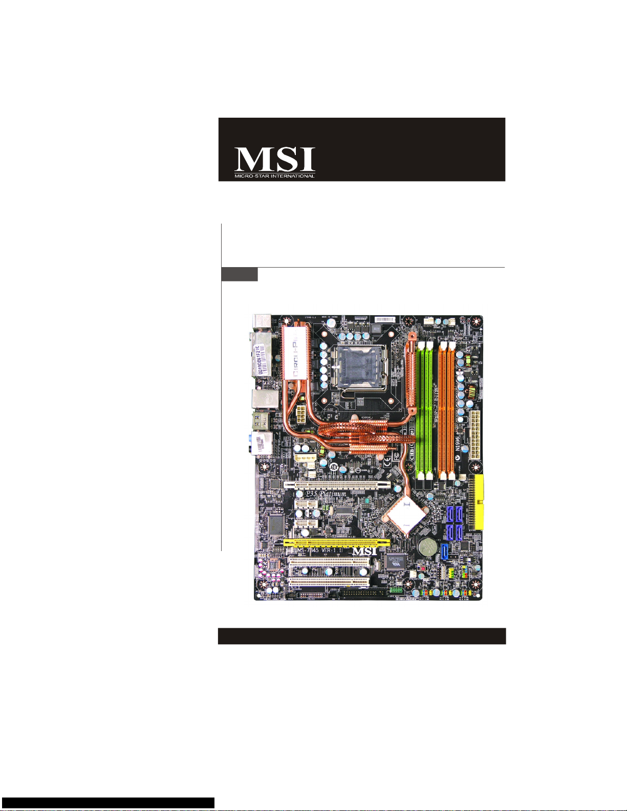
P35 Platinum Series
MS-7345 (V1.X) Mainboard
G52-73451X6
Page 2

ii
Copyright Notice
The material in this document is the intellectual property of MICRO-STAR
INTERNATIONAL. We take every care in the preparation of this document, but no
guarantee is given as to the correctness of its contents. Our products are under
continual improvement and we reserve the right to make changes without notice.
Trademarks
All trademarks are the properties of their respective owners.
NVIDIA, the NVIDIA logo, DualNet, and nForce are registered trademarks or trade-
marks of NVIDIA Corporation in the United States and/or other countries.
AMD, Athlon™, Athlon™ XP, Thoroughbred™, and Duron™ are registered trademarks of AMD Corporation.
Intel® and Pentium® are registered trademarks of Intel Corporation.
PS/2 and OS®/2 are registered trademarks of International Business Machines
Corporation.
Windows® 95/98/2000/NT/XP are registered trademarks of Microsoft Corporation.
Netware® is a registered trademark of Novell, Inc.
Award® is a registered trademark of Phoenix Technologies Ltd.
AMI® is a registered trademark of American Megatrends Inc.
Revision History
Revision Revision History Date
V1.1 First release for April 2007
P35 Platinum
Technical Support
If a problem arises with your system and no solution can be obtained from the user’s
manual, please contact your place of purchase or local distributor. Alternatively,
please try the following help resources for further guidance.
Visit the MSI website for FAQ, technical guide, BIOS updates, driver updates,
and other information: http://global.msi.com.tw/index.php?
func=faqIndex
Contact our technical staff at: http://support.msi.com.tw/
Page 3
iii
Safety Instructions
CAUTION: Danger of explosion if battery is incorrectly replaced.
Replace only with the same or equivalent type recommended by the
manufacturer.
1. Always read the safety instructions carefully.
2. Keep this User’s Manual for future reference.
3. Keep this equipment away from humidity.
4. Lay this equipment on a reliable flat surface before setting it up.
5. The openings on the enclosure are for air convection hence protects the equipment from overheating. DO NOT COVER THE OPENINGS.
6. Make sure the voltage of the power source and adjust properly 110/220V before connecting the equipment to the power inlet.
7. Place the power cord such a way that people can not step on it. Do not place
anything over the power cord.
8. Always Unplug the Power Cord before inserting any add-on card or module.
9. All cautions and warnings on the equipment should be noted.
10. Never pour any liquid into the opening that could damage or cause electrical
shock.
11. If any of the following situations arises, get the equipment checked by a service
personnel:
† The power cord or plug is damaged.
† Liquid has penetrated into the equipment.
† The equipment has been exposed to moisture.
† The equipment has not work well or you can not get it work according to
User’s Manual.
† The equipment has dropped and damaged.
† The equipment has obvious sign of breakage.
12. DO NOT LEAVE THIS EQUIPMENT IN AN ENVIRONMENT UNCONDITIONED, STORAGE TEMPERATURE ABOVE 600 C (1400F), IT MAY DAMAGE THE EQUIPMENT.
Page 4
iv
FCC-B Radio Frequency Interference Statement
This equipment has been
tested and found to comply
with the limits for a Class B
digital device, pursuant to Part
15 of the FCC Rules. These limits are designed to provide reasonable protection
against harmful interference in a residential installation. This equipment generates,
uses and can radiate radio frequency energy and, if not installed and used in accordance with the instructions, may cause harmful interference to radio communications.
However, there is no guarantee that interference will not occur in a particular
installation. If this equipment does cause harmful interference to radio or television
reception, which can be determined by turning the equipment off and on, the user is
encouraged to try to correct the interference by one or more of the measures listed
below.
† Reorient or relocate the receiving antenna.
† Increase the separation between the equipment and receiver.
† Connect the equipment into an outlet on a circuit different from that to
which the receiver is connected.
† Consult the dealer or an experienced radio/television technician for help.
Notice 1
The changes or modifications not expressly approved by the party responsible for
compliance could void the user’s authority to operate the equipment.
Notice 2
Shielded interface cables and A.C. power cord, if any, must be used in order to
comply with the emission limits.
VOIR LA NOTICE D’INSTALLATION AVANT DE RACCORDER AU RESEAU.
Micro-Star International
MS-7345
This device complies with Part 15 of the FCC Rules. Operation is subject to the
following two conditions:
(1) this device may not cause harmful interference, and
(2) this device must accept any interference received, including interference that
may cause undesired operation.
Page 5
v
WEEE (Waste Electrical and Electronic Equipment) Statement
vi
Page 6
Page 7
vii viii
Page 8

CONTENTS
Copyright Notice.........................................................................................................ii
Trademarks..................................................................................................................ii
Revision History.........................................................................................................ii
Technical Support......................................................................................................ii
Safety Instructions...................................................................................................iii
FCC-B Radio Frequency Interference Statement.............................................iv
WEEE (Waste Electrical and Electronic Equipment) Statement.......................v
English......................................................................................................................En-1
Specifications....................................................................................................En-2
Central Processing Unit: CPU...........................................................................En-5
Memory...............................................................................................................En-7
Connectors, Jumpers, Slots.............................................................................En-9
Back Panel........................................................................................................En-18
LED Status Indicators......................................................................................En-21
BIOS Setup.......................................................................................................En-23
Software Information......................................................................................En-27
Deutsch....................................................................................................................De-1
Spezifikationen..................................................................................................De-2
Hauptprozessor: CPU.......................................................................................De-5
Speicher.............................................................................................................De-7
Anschlüsse, Steckbrücken und Slots.............................................................De-9
Hinteres Anschlusspaneel.............................................................................De-18
LED Statusdikatoren........................................................................................De-21
BIOS Setup.......................................................................................................De-23
Software-Information......................................................................................De-27
Français.....................................................................................................................Fr-1
Spécificités.........................................................................................................Fr-2
Central Processing Unit: CPU............................................................................Fr-5
Mémoire...............................................................................................................Fr-7
Connecteurs, Cavaliers, Slots..........................................................................Fr-9
Panneau Arrière...............................................................................................Fr-18
Indicateur d’état LED........................................................................................Fr-21
Configuration du BIOS......................................................................................Fr-23
Information de Logiciel.....................................................................................Fr-27
Русский ....................................................................................................................Ru-1
Характеристики ...............................................................................................Ru-2
Центральный процессор (CPU).....................................................................Ru-5
Папять ...............................................................................................................Ru-7
Соединители, перемычки, разъемы ............................................................Ru-9
Задняя панель ...............................................................................................Ru-18
Состояние идикаторов LED........................................................................Ru-21
Настройка BIOS..............................................................................................Ru-23
Сведения о программном обеспечении ...................................................Ru-27
Page 9

En-1
English
P35 Platinum
User’s Guide
English
Page 10

En-2
MS-7345 Mainboard
Specifications
Processor Support
- Intel® Core 2 Quad/Core 2 Duo/Pentium/Celeron processors in the
LGA775 package
- Support Intel® Yorkfield, Wolfdale
(For the latest information about CPU, please visit http://global.msi.
com.tw/index.php?func=cpuform)
Supported FSB
- 1333/ 1066/ 800 MHz
Chipset
- North Bridge: Intel® P35 chipset
- South Bridge: Intel® ICH9R chipset
Memory Support
- DDR2 800/667 SDRAM (8GB Max)
- 4 DDR2 DIMMs (240pin / 1.8V)
(For more information on compatible components, please visit http:/
/global.msi.com.tw/index.php?func=testreport)
LAN
- Supports PCIE LAN 10/100/1000 Fast Ethernet by Realtek 8111B
Audio
- Chip integrated by Realtek® ALC888/ALC888T
- Flexible 8-channel audio with jack sensing
- Compliant with Azalia 1.0 Spec
- Meet Microsoft Vista Premium spec
- Supports VoIP Card (only for ALC888T)
IDE
- 1 IDE port by Marvell 88SE6111
- Supports Ultra DMA 66/100/133 mode
- Supports PIO, Bus Master operation mode
SATA
- 4 SATAII ports with 2 eSATA by ICH9R
- 1 SATA II port by Marvell 88SE6111
- Supports storage and data transfers at up to 300 MB/s
RAID
- Supports Intel Martix Storage Technology (AHCI + RAID 0/1/5/10)
by ICH9R
1394
- Supports 1394 by VIA VT6308
Page 11
En-3
English
FDD
- 1 floppy port
- Supports 1 FDD with 360KB, 720KB, 1.2MB, 1.44MB and 2.88MB
Connectors
Back panel
- 1 PS/2 mouse port
- 1 PS/2 keyboard port
- 2 eSATA ports (support Command Based Port Multipliers)
- 6 USB 2.0 Ports
- 1 LAN jack (10/100/1000)
- 6 flexible audio jacks
- 1 1394 port (optional)
- 1 Optical S/PDIF-Out (optional)
On-Board Pinheaders / Connectors
- 3 USB 2.0 pinheaders
- 1 1394 pinheader (optional)
- 1 chasis intrusion connector
- 1 SPDIF-out pinheader
- 1 CD-in connector
- 2 H/W OC pinheaders (optional)
- 1 front audio pinheader
- 1 serial pinheader
Slots
- 1 PCI Express x16 slot
- 2 PCI Express x1 slots
- 1 PCI Express x4 slot
- 2 PCI slots
- Support 3.3V/ 5V PCI bus Interface
Form Factor
- ATX (30.5cm X 24.5cm)
Mounting
- 9 mounting holes
Page 12

En-4
MS-7345 Mainboard
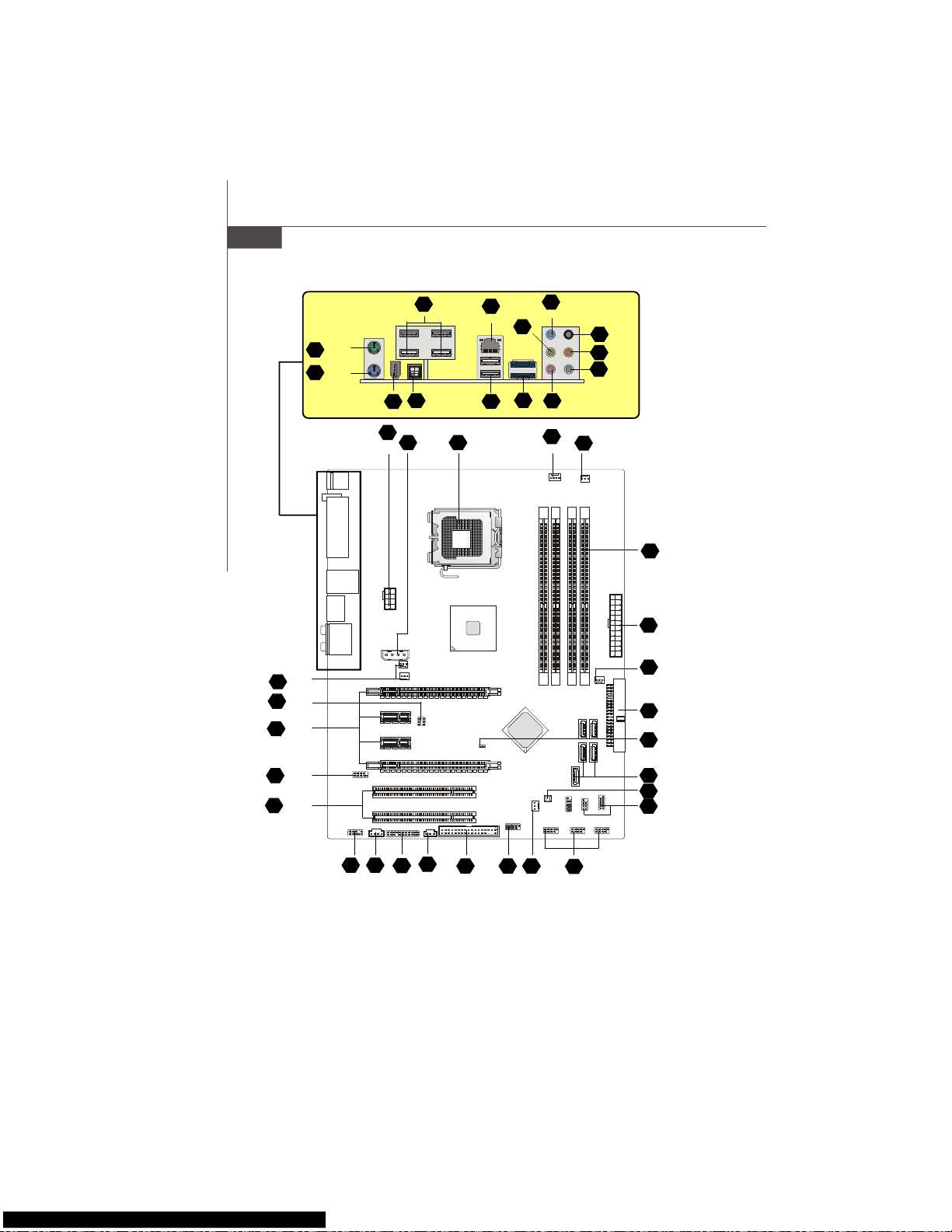
Quick Components Guide of P35 Platinum Series
(MS-7345 v1.X) Mainboard
1
En-5
4
En-9
3
En-7
22
En-15
4
En-9
6
En-9
15
En-12
7
En-10
21
En-15
8 En-10
10
En-11
4
En-9
4
En-9
9
En-10
11
En-11
5
En-9
12
En-11
14
En-12
17
En-13
28
En-17
29
En-17
19
En-13
4
En-9
25
En-16
26
En-16
A
En-18
A
En-18
H En-20
F
En-19
P
En-20
G
En-19
H
En-20
Q
En-20
K En-20
L En-20
N En-20
En-20
I
J
En-20
M En-20
13 En-12
Page 13

En-5
English
The mainboard supports Intel® processor. The mainboard uses a CPU socket called
Socket 775 for easy CPU installation. If you do not have the CPU cooler, consult your
dealer before turning on the computer.
For the latest information about CPU, please visit http://global.msi.com.tw/index.php?
func=cpuform
1
Central Processing Unit: CPU
Important
Overheating
Overheating will seriously damage the CPU and system. Always make sure the
cooling fan can work properly to protect the CPU from overheating. Make sure
that you apply an even layer of thermal paste (or thermal tape) between the CPU
and the heatsink to enhance heat dissipation.
Replaceing the CPU
While replacing the CPU, always turn off the ATX power supply or unplug the
power supply’s power cord from the grounded outlet first to ensure the safety of
CPU.
Overclocking
This mainboard is designed to support overclocking. However, please make
sure your components are able to tolerate such abnormal setting, while doing
overclocking. Any attempt to operate beyond product specifications is not
recommended. We do not guarantee the damages or risks caused by inad-
equate operation or beyond product specifications.
Page 14
En-6
MS-7345 Mainboard
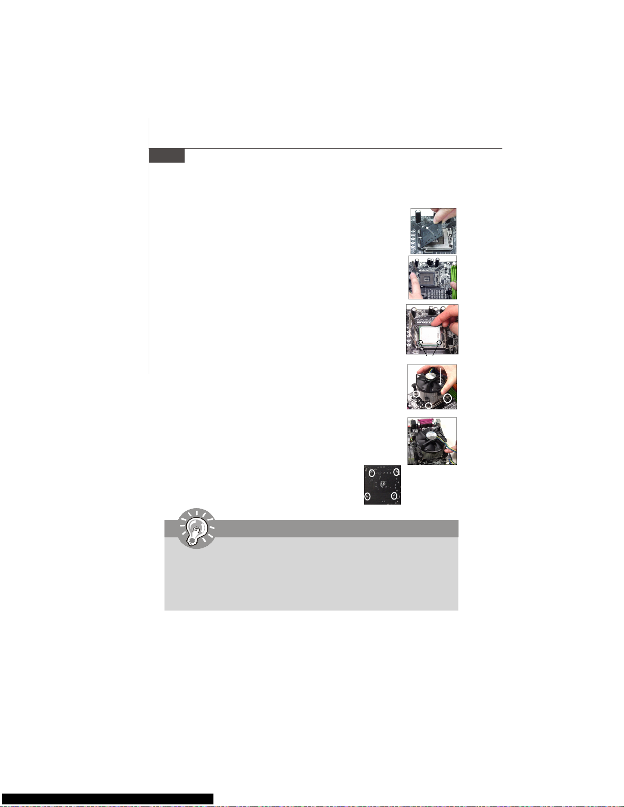
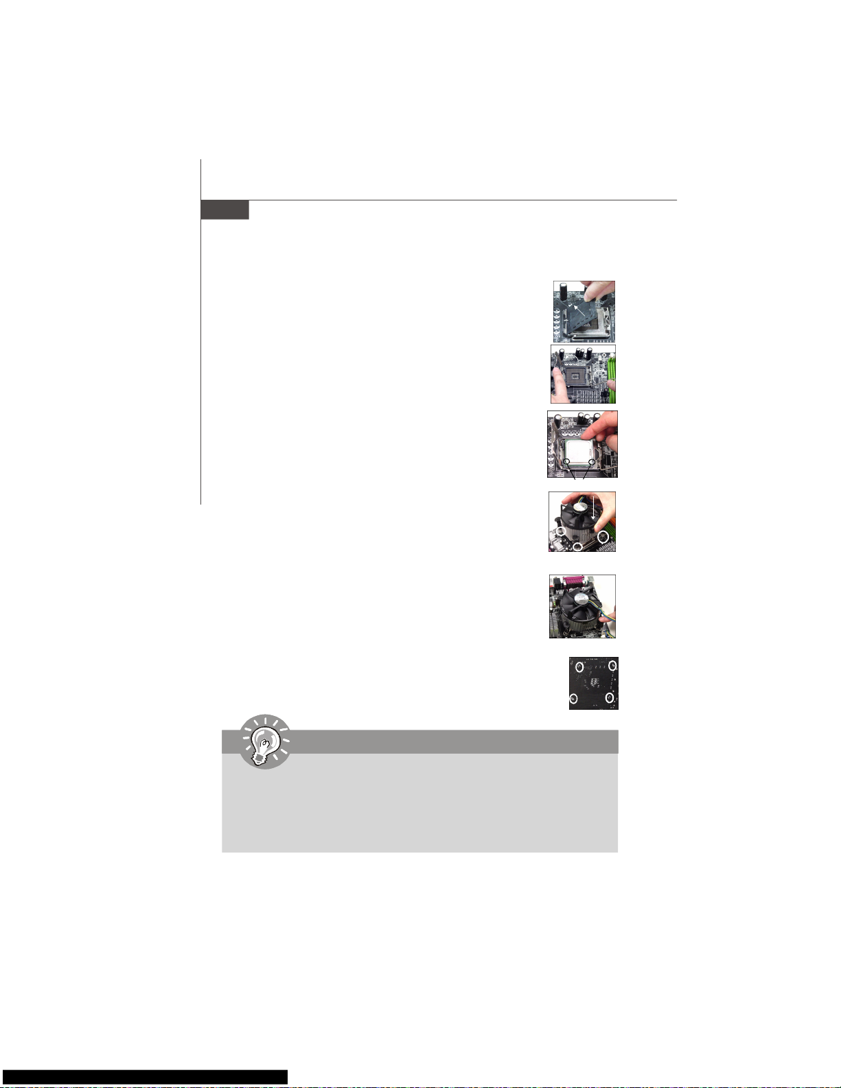
CPU & Cooler Installation Procedures for Socket 775
1. The CPU socket has a plastic cap on it to protect the contact from
damage. Before you have installed the CPU, always cover it to protect the socket pin.
2. Remove the cap from lever hinge side.
3. The pins of socket reveal.
4. Open the load lever.
5. Lift the load lever up and open the load plate.
6. After confirming the CPU direction for correct mating, put down the
CPU in the socket housing frame. Be sure to grasp on the edge of the
CPU base. Note that the alignment keys are matched.
7. Visually inspect if the CPU is seated well into the socket. If not, take
out the CPU with pure vertical motion and reinstall.
8. Cover the load plate onto the package.
9. Press down the load lever lightly onto the load plate, and then
secure the lever with the hook under retention tab.
10.Align the holes on the mainboard with the cooler. Push down the
cooler until its four clips get wedged into the holes of the mainboard.
11.Press the four hooks down to fasten the cooler. Then rotate the
locking switch (refer to the correct direction marked on it) to lock the
hooks.
12.Turn over the mainboard to confirm that the clip-ends
are correctly inserted.
alignment key
Important
1. Read the CPU status in BIOS.
2. Whenever CPU is not installed, always protect your CPU socket pin with the
plastic cap covered to avoid damaging.
3. Mainboard photos shown in this section are for demonstration of the CPU/
cooler installation only. The appearance of your mainboard may vary depending on the model you purchase.
Page 15
En-7
English
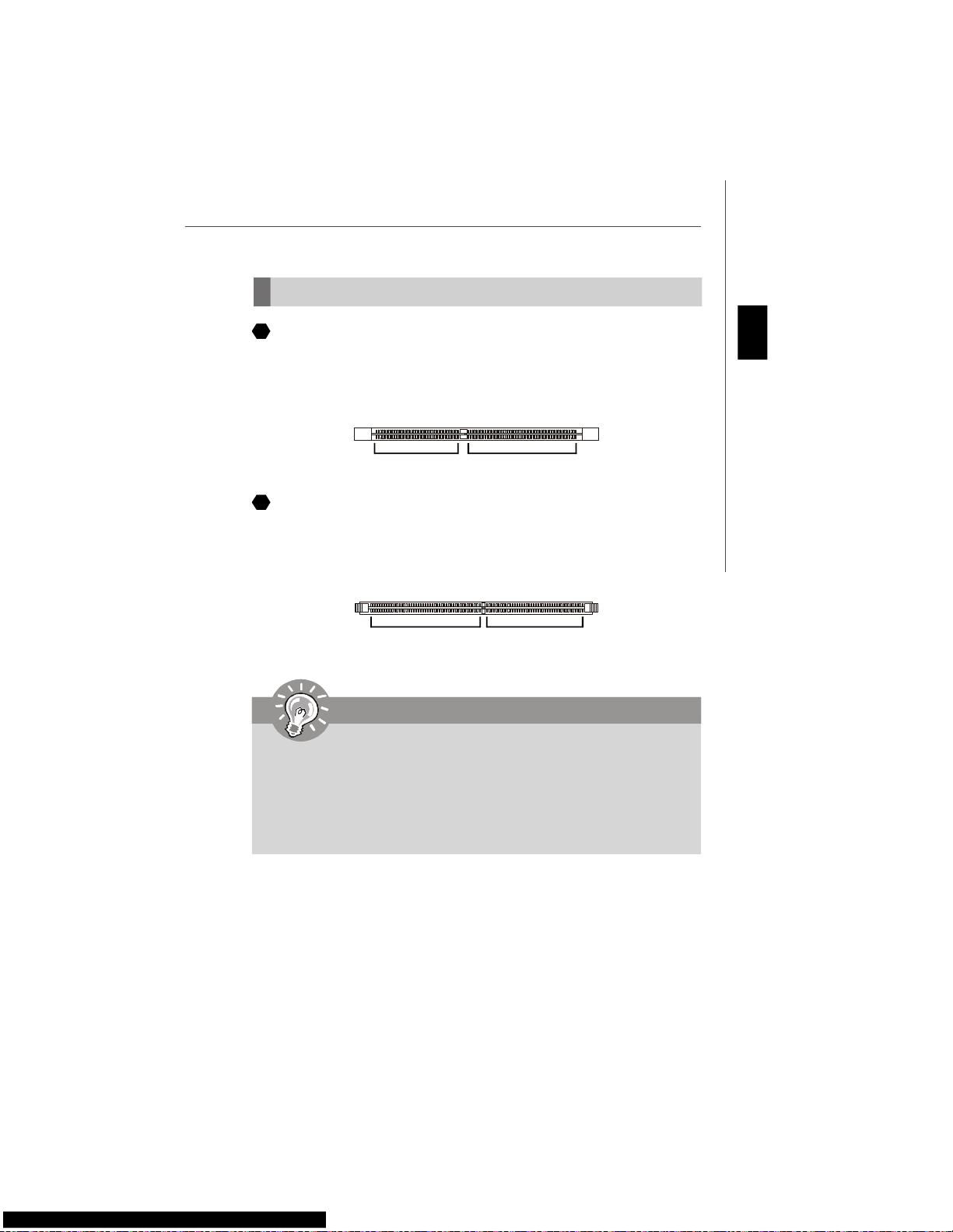
Memory
DDR
Specification : 184-pin, 2.5v.
Single channel definition : All DIMM slots are GREEN color.
Dual channels definition : DIMM slot(s) on Channel A are marked in GREEN color.
DIMM slot(s) on Channel B are marked in Purple color.
DDR2
Specification : 240-pin, 1.8v.
Single channel definition : All DIMM slots are GREEN color.
Dual channels definition : DIMM slot(s) on Channel A are marked in GREEN color.
DIMM slot(s) on Channel B are marked in Orange color.
64x2=128 pin 56x2=112 pin
40x2=80 pin 52x2=104 pin
2
3
Important
- DDR2 memory modules are not interchangeable with DDR and the DDR2 stan
dard is not backwards compatible. You should always install DDR2 memory
modules in the DDR2 DIMM slots.
- In Dual-Channel mode, make sure that you install memory modules of the same
type and density in different channel DIMM slots.
- To enable successful system boot-up, always insert the memory modules into the
DIMM1 first.
Page 16
En-8
MS-7345 Mainboard
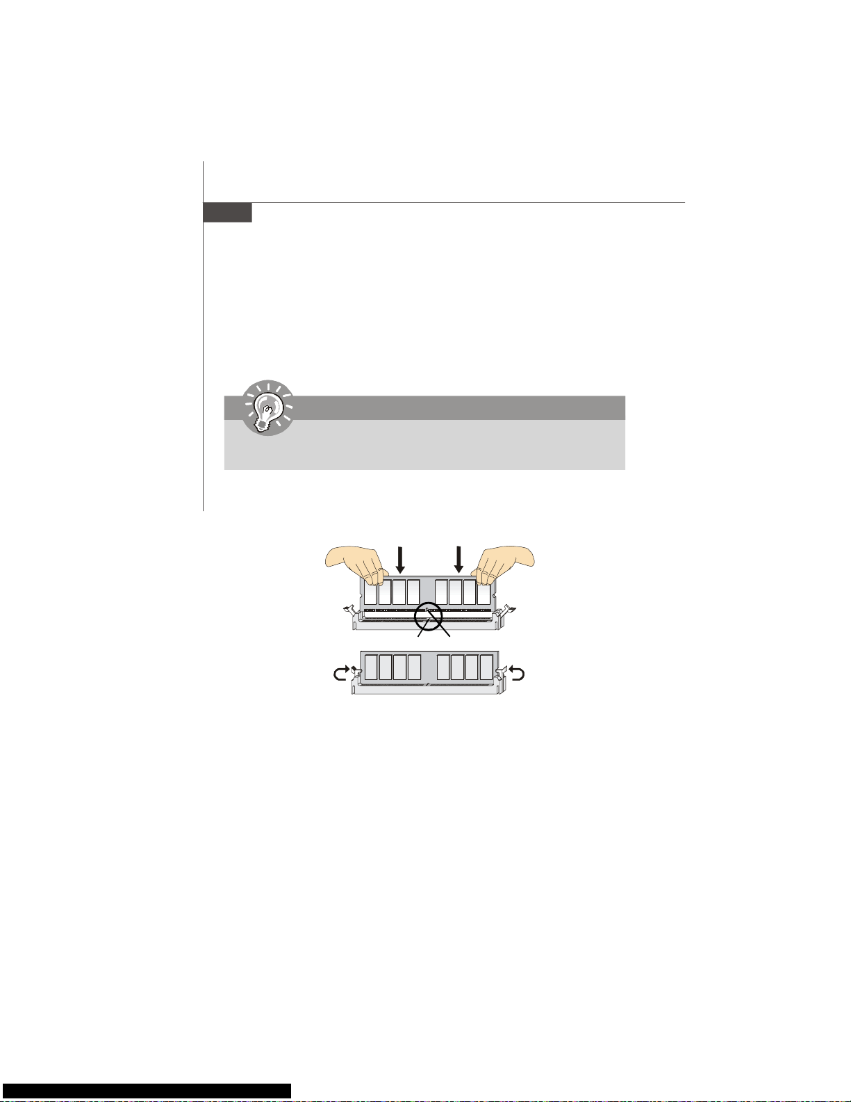
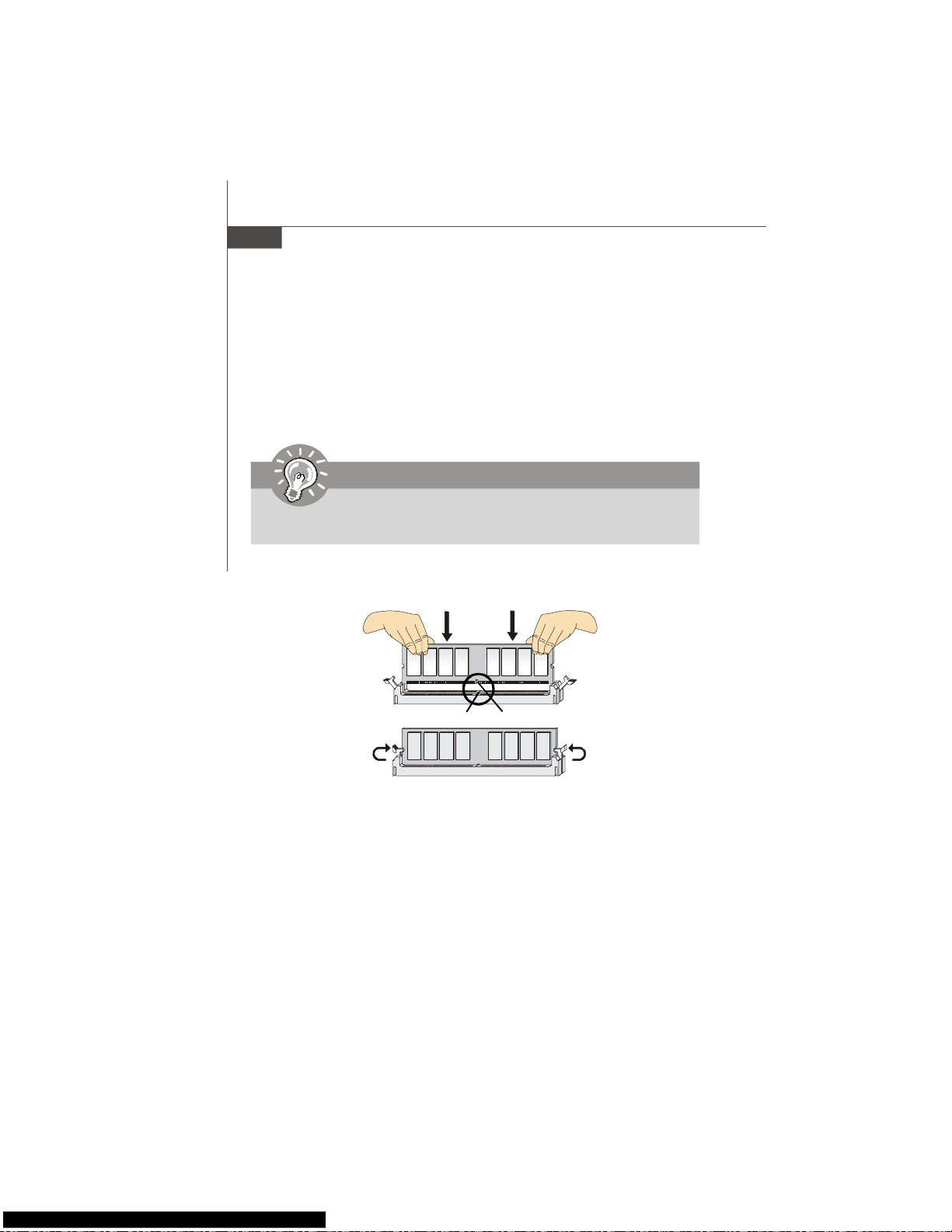
Installing Memory Modules
You can find the notch on the memory modules and the volt on the DIMM slots whether
DDR or DDR2. Follow the procedures below to install the memory module properly.
1.The memory modules has only one notch on the center and will only fit in the right
orientation.
2.Insert the memory module vertically into the DIMM slot. Then push it in until the
golden finger on the memory module is deeply inserted in the DIMM slot.
3.The plastic clip at each side of the DIMM slot will automatically close.
Important
You can barely see the golden finger if the memory module is properly inserted in
the DIMM slot.
Volt
Notch
Page 17
En-9
English
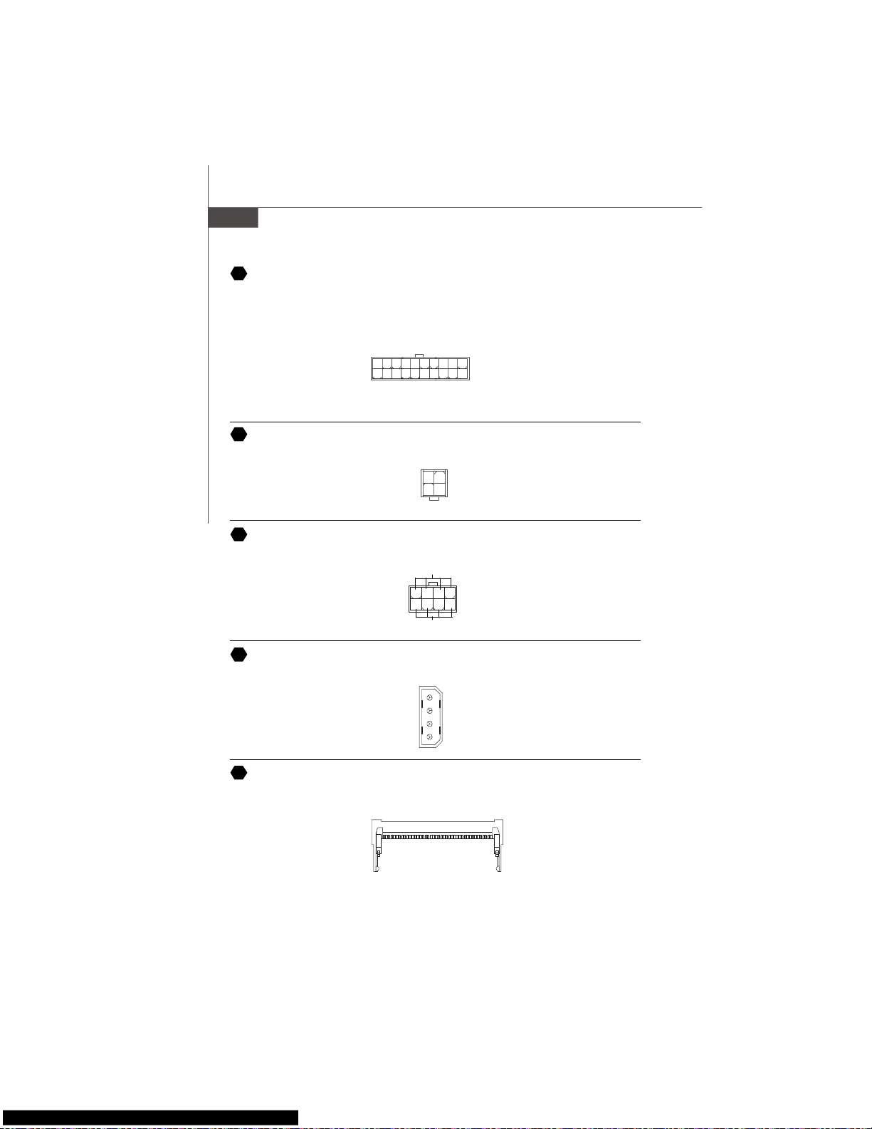
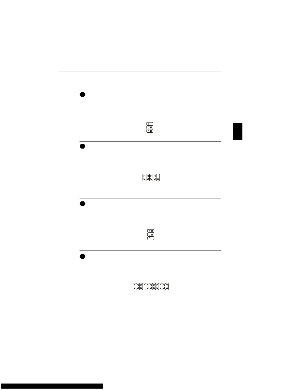
Connectors, Jumpers, Slots
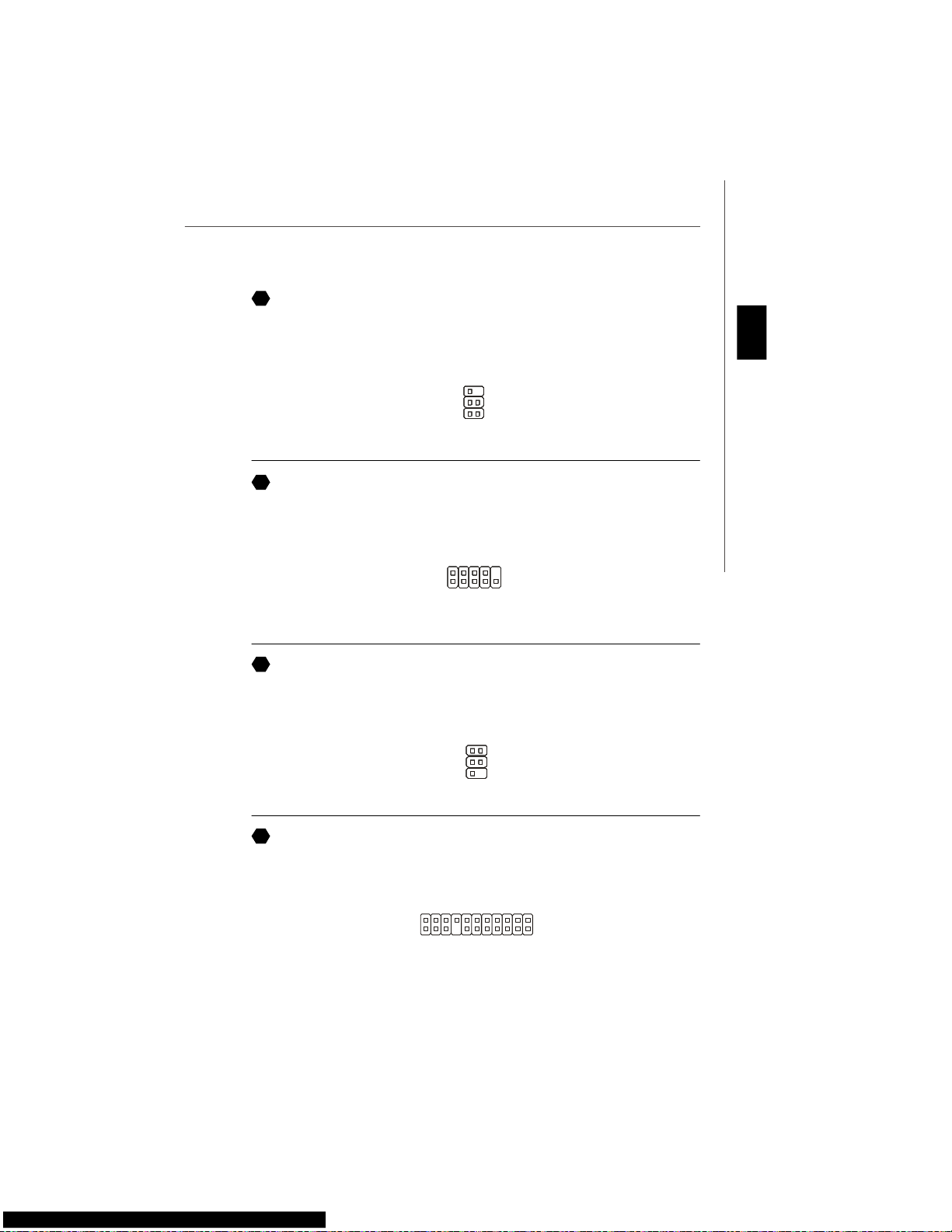
Floppy Disk Drive Connector
This connector supports 360KB, 720KB, 1.2MB, 1.44MB or 2.88MB floppy disk drive.
5
Fan Power Connectors
The fan power connectors support system cooling fan with +12V. The CPU FAN supports
Smart FAN function. When connect the wire to the connectors, always take note that the
red wire is the positive and should be connected to the +12V, the black wire is Ground
and should be connected to GND. If the mainboard has a System Hardware Monitor
chipset on-board, you must use a specially designed fan with speed sensor to take
advantage of the fan control.
SYS FAN/ NB FAN/
POWER FAN
SENSOR or NC
+12V
GND
4
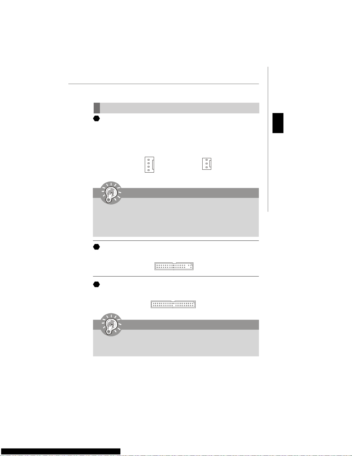
IDE connector
This connector supports IDE hard disk drives, optical disk drives and other IDE devices.
6
CPU FAN
SENSOR
+12V
GND
Control
Important
1.Please refer to the recommended CPU fans at processor’s official website or
consult the vendors for proper CPU cooling fan.
2.CPUFAN supports fan control. You can install Dual Core Center utility that
will automatically control the CPU fan speed according to the actual CPU
temperature.
3. Fan cooler set with 3 or 4 pins power connector are both available for CPUFAN.
Important
If you install two IDE devices on the same cable, you must configure the drives
separately to Master/ Slave mode by setting jumpers. Refer to IDE device’s docu-
mentation supplied by the vendors for jumper setting instructions.
Page 18
En-10
MS-7345 Mainboard
Front Panel Connectors
These connectors are for electrical connection to the front panel switches and LEDs.
The JFP1 is compliant with Intel® Front Panel I/O Connectivity Design Guide.
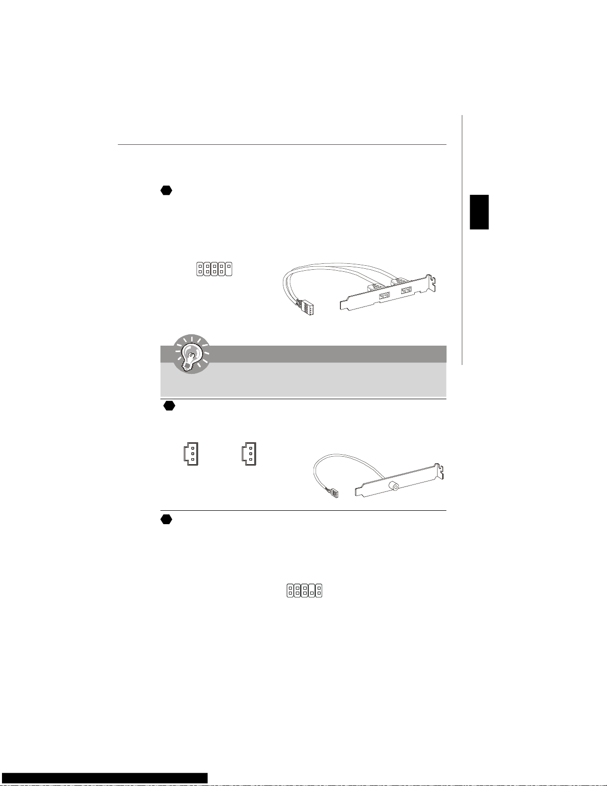
IEEE1394 Connector (Green)
This connector allows you to connect the IEEE1394 device via an optional IEEE1394
bracket.
8
9
Serial ATA Connector
This connector is a high-speed Serial ATA interface port. Each connector can connect to
one Serial ATA device.
7
Important
Please do not fold the Serial ATA cable into 90-degree angle. Otherwise, data
loss may occur during transmission.
IEEE1394 Bracket
(Optional)
JFP2
7
8
Power LED
Speaker
12
JFP1
1
2
910
HDD
LED
Reset
Switch
Power
LED
Power
Switch
1
2
9
10
TPA-
Ground
TPB-
Cable power
Ground
TPA+
Ground
TPB+
Cable power
Key (no pin)
Page 19
En-11
English
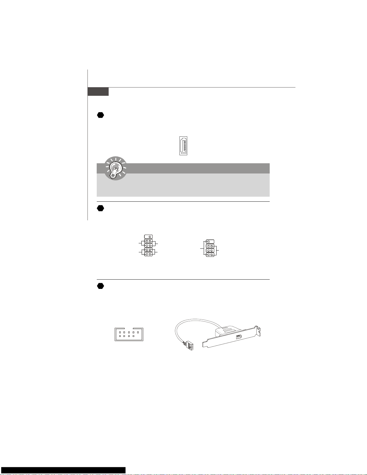
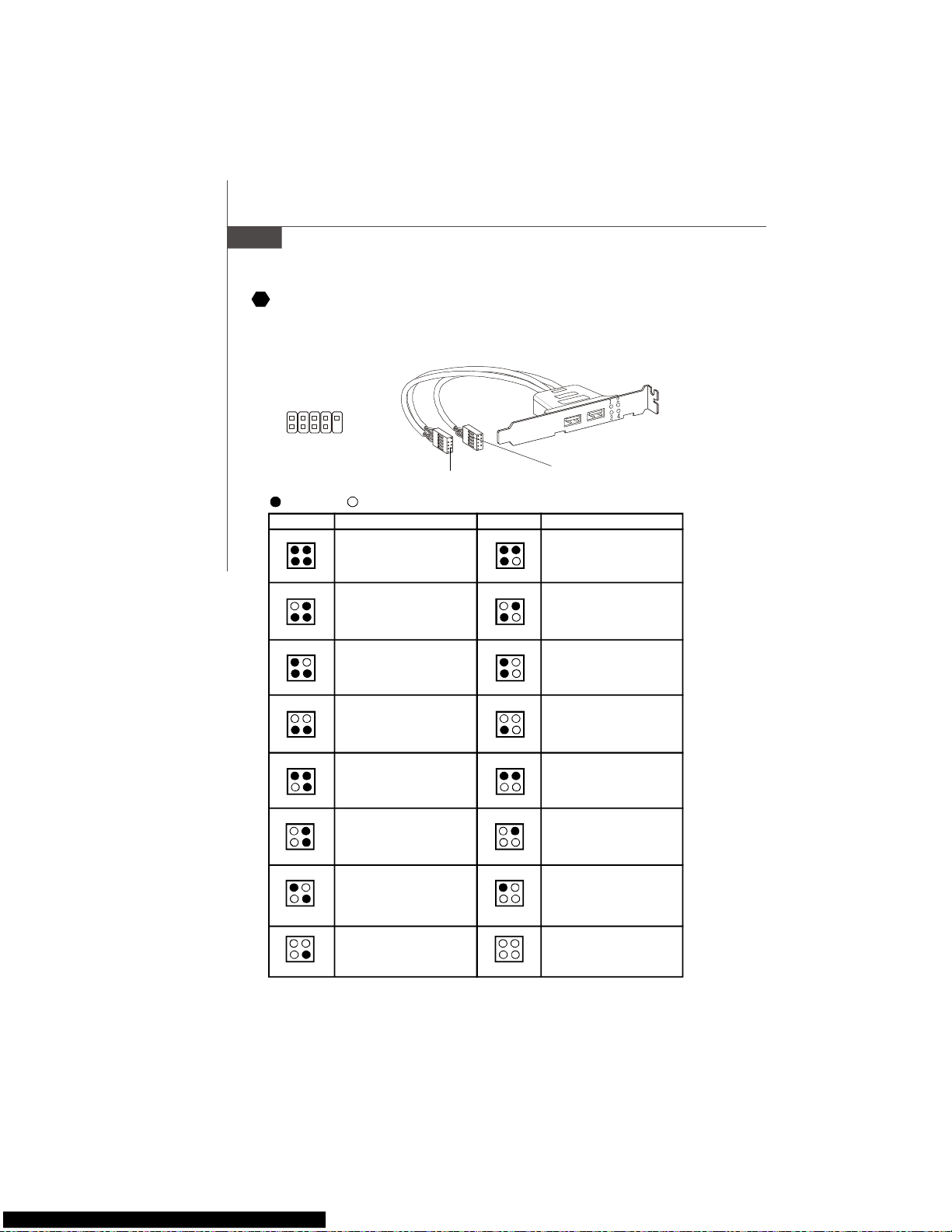
Front USB Connector (Yellow)
This connector, compliant with Intel® I/O Connectivity Design Guide, is ideal for connecting high-speed USB interface peripherals such as USB HDD, digital cameras, MP3
players, printers, modems and the like.
Important
Note that the pins of VCC and GND must be connected correctly to avoid possible
damage.
10
Front Panel Audio Connector (Azalia Spec)
This connector allows you to connect the front panel audio and is compliant with Intel
®
Front Panel I/O Connectivity Design Guide.
12
USB 2.0 Bracket
(Optional)
USBOC
10
1
2
VCC
USB0-
USB0+
GND
Key (no pin)
VCC
USB1-
USB1+
GND
9
1
2
9
10
MIC _L
MIC _R
LINE out_R
Front_JD
LINE out_L
Ground
Presence#
MIC_JD
NC(No pin)
LINE out_JD
S/PDIF-Out Connector or S/PDIF-In Connector
This connector is used to connect S/PDIF (Sony & Philips Digital Interconnect Format)
interface for digital audio transmission.
SPDIF Bracket (Optional)
SPDIF_In
VCC
SPDIF_in
GND
SPDIF_Out
VCC
SPDIF_out
GND
11
Page 20
En-12
MS-7345 Mainboard
CD-In Connector
This connector is provided for external audio input.
Chassis Intrusion Connector
This connector connects to the chassis intrusion switch cable. If the chassis is opened,
the chassis intrusion mechanism will be activated. The system will record this status and
show a warning message on the screen. To clear the warning, you must enter the BIOS
utility and clear the record.
GND R
L
15
13
14
1
2
CINTRU
GND
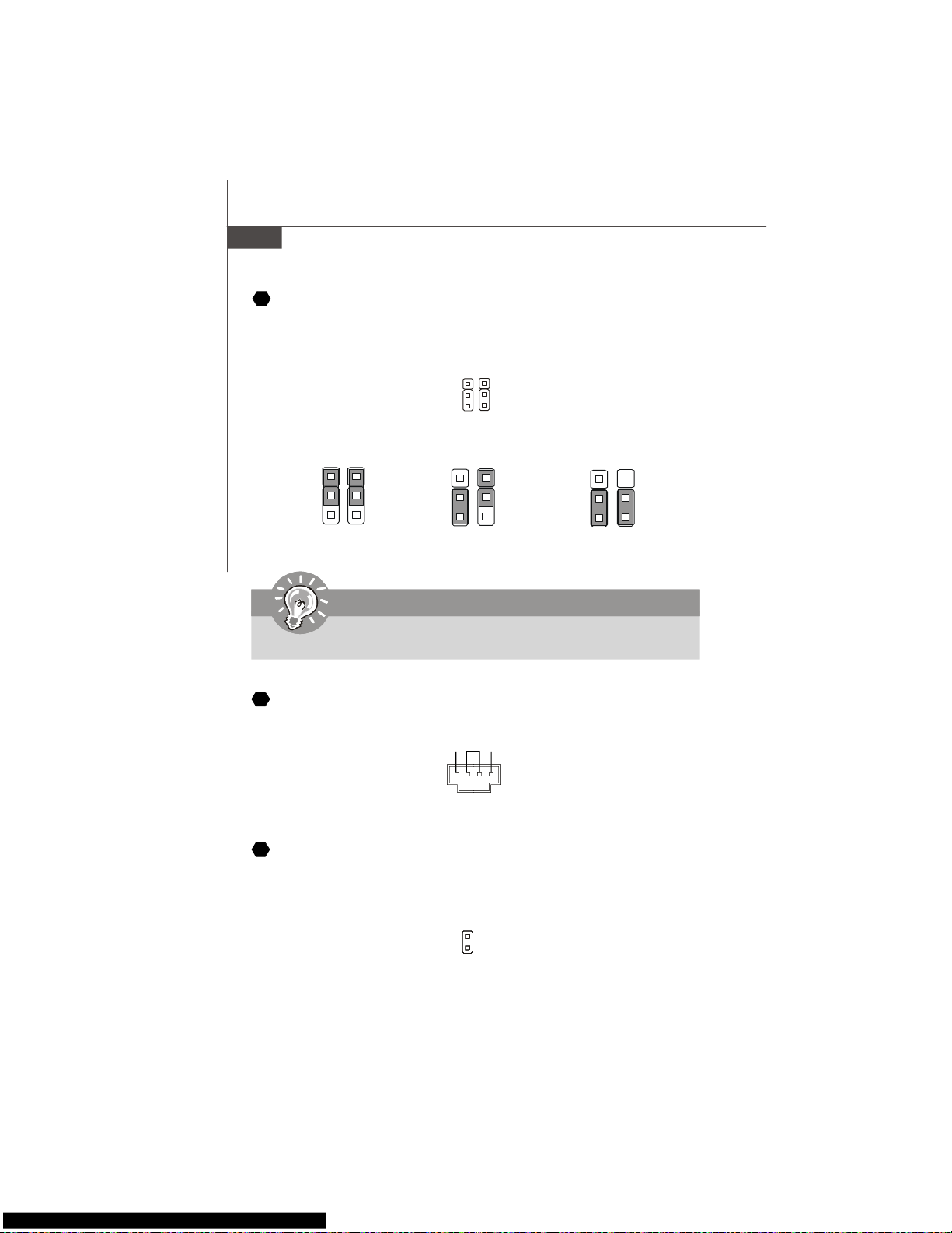
Hardware Overclock FSB Jumpers: JB1, JB2 (optional)
You can overclock the FSB to increase the processor frequency by changing the jumpers
JB1 and JB2. Follow the instructions below to set the FSB.
Important
Make sure that you power off the system before changing the jumpers
1
266 MHz
1
3
200 MHz
1
3
JB1 JB2
333 MHz
1
3
Page 21
En-13
English
Infrared Module Connector
This connector allows you to connect to infrared module and is compliant with Intel
®
Front Panel I/O Connectivity Design Guide. You must configure the setting through the
BIOS setup to use the infrared function.
Serial Port Connector
This connector is a 16550A high speed communication port that sends/receives 16
bytes FIFOs. You can attach a serial device.
TV-Out Connector
This connector is for you to attach an optional TV-Out bracket that offers some types of
TV-Out connectors. Select the appropriate one to connect to an television.
6
5
2
1
NC
VCC5
IRTX
NC
Ground
IRRX
16
17
18
3
1 4
Ground
Yout
Cout
COMP or CVBS
Ground (5)
1
5
6
DCD
SIN
SOUT
DTR
Ground
DSR
RTS
CTS
RI (9)
VoIP Card Connector
This connector connects to the VoIP card. Please refer to the instruction of the VoIP
card.
19
Page 22
En-14
MS-7345 Mainboard
BIOS Sign On
This will start showing information
about logo, processor brand name,
etc...
Testing Base and Extended Memory
Testing base memory from 240K to
640K and extended memory above
1MB using various patterns.
Assign Resources to all ISA.
Initializing Hard Drive Controller
This will initialize IDE drive and
controller.
Initializing Floppy Drive Controller
This will initialize Floppy Drive and
controller.
Boot Attempt
This will set low stack and boot via
INT 19h.
Operating System Booting
System Power ON
The D-LED will hang here if the
processor is damaged or not installed properly.
Initializing Keyboard Controller.
Testing VGA BIOS
This will start writing VGA sign-on
message to the screen.
Processor Initialization
This will show information regarding
the processor (like brand name, system bus, etc...)
Testing RTC (Real Time Clock)
Description
Red
Green
LED Signal
1 2
3 4
1 2
3 4
1 2
3 4
1 2
3 4
1 2
3 4
1 2
3 4
1 2
3 4
1 2
3 4
Description
LED Signal
1 2
3 4
1 2
3 4
1 2
3 4
1 2
3 4
1 2
3 4
1 2
3 4
1 2
3 4
1 2
3 4
Early Chipset Initialization
Memory Detection Test
Testing onboard memory size. The
D-LED will hang if the memory module is damaged or not installed
properly.
Decompressing BIOS image to RAM
for fast booting.
Initializing Video Interface
This will start detecting CPU clock,
checking type of video onboard. Then,
detect and initialize the video adapter.
D-Bracket™ 2 Connector
This connector is for you to connect to the D-Bracket™2 which integrates four LEDs and
USB ports. It allows users to identify system problems through 16 various combinations
of LED signals.
20
D-Bracket™ 2
(Optional)
Connected to DBracket 2 connector
Connected to USB connector
1
9
2
10
DBG1
DBG2
DBG3
DBG4
Key
DBR1
DBR2
DBR3
DBR4
NC
Page 23

En-15
English
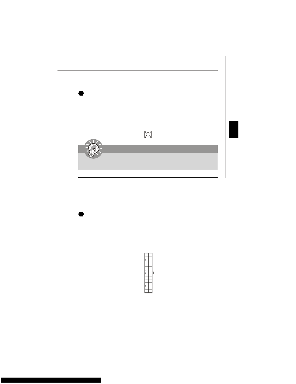
Clear CMOS Button
The CMOS RAM onboard has a power supply from external battery to keep the data of
system configuration. With the CMOS RAM, the system can automatically boot OS
every time it is turned on. If you want to clear the system configuration, use the button
to clear data. Press the button to clear the data.
Power Supply Attachment
Before inserting the power supply connector, always make sure that all components are
installed properly to ensure that no damage will be caused. All power connectors on
the mainbnoard have to connect to the ATX power supply and have to work together to
ensure stable operation of the mainboard.
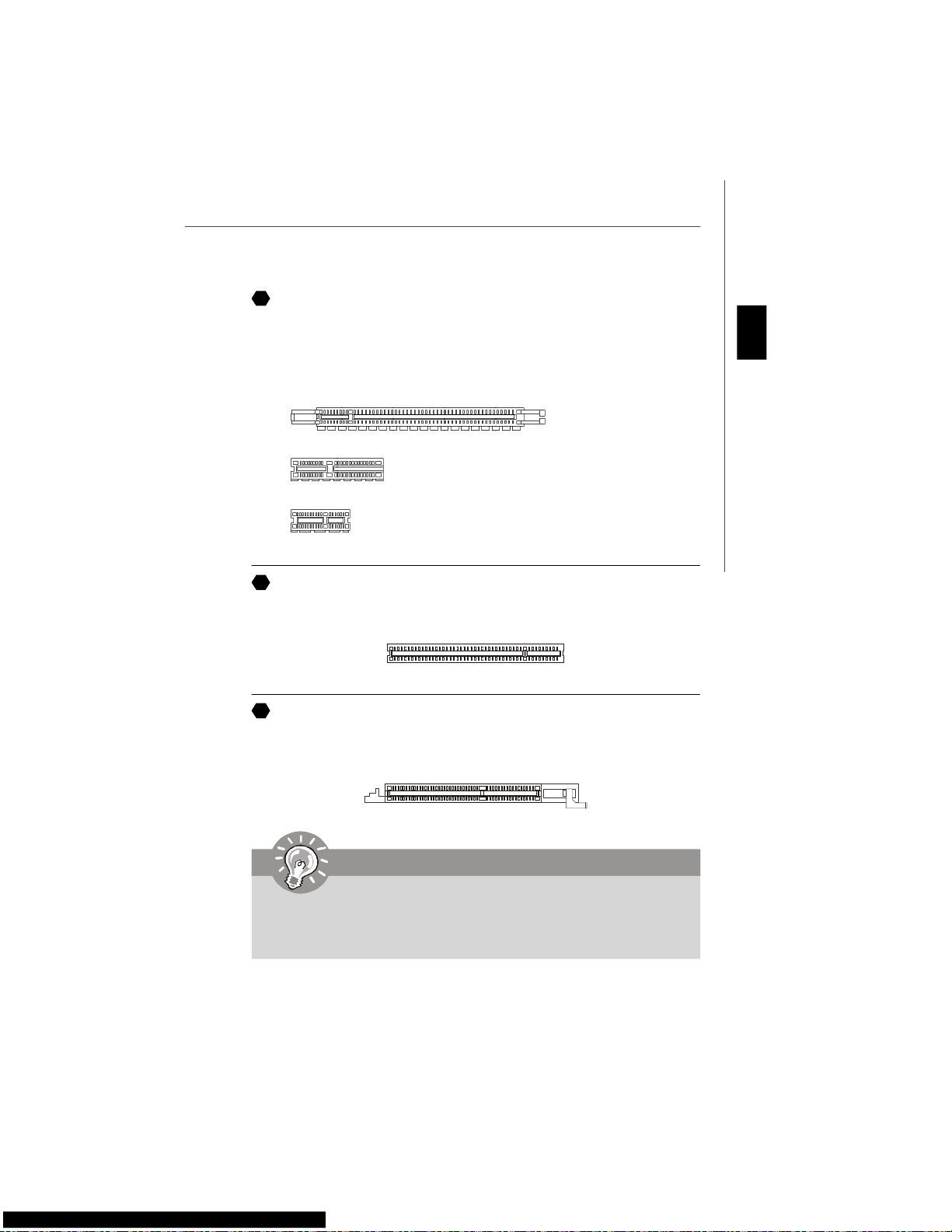
ATX 24-Pin Power Connector
This connector allows you to connect an ATX 24-pin power supply. To connect the ATX
24-pin power supply, make sure the plug of the power supply is inserted in the proper
orientation and the pins are aligned. Then push down the power supply firmly into the
connector.
You may use the 20-pin ATX power supply as you like. If you’d like to use the 20-pin ATX
power supply, please plug your power supply along with pin 1 & pin 13.
21
Important
Make sure that you power off the system before clearing CMOS data.
22
1
1224
13
+3.3V
+3.3V
GND
+5V
GND
+5V
GND
PWR OK
5VSB
+12V
+12V
+3.3V
GND
+5V
+5V
+5V
NC
GND
GND
GND
PS-ON#
GND
-12V
+3.3V
Page 24
En-16
MS-7345 Mainboard
NV SLI Connector
This connector is used to configure the SLI switch card to SLI or non-SLI mode.
ATX 12V Power Connector (2x2-Pin)
This 12V power connector is used to provide power to the CPU.
ATX 12V Power Connector (2x4-Pin)
This 12V power connector is used to provide power to the CPU.
ATX 12V Power Connector (1x4-Pin)
This 12V power connector is used to provide power to the graphics card.
1
34
2
GND
12V
GND
12V
4
2
1
3
5V
GND
GND
12V
ATX 20-Pin Power Connector
This connector allows you to connect an ATX 20-pin power supply. To connect the ATX
20-pin power supply, make sure the plug of the power supply is inserted in the proper
orientation and the pins are aligned. Then push down the power supply firmly into the
connector.
1
10 20
11
3.3V
3.3V
GND
5V
GND5VGND
PWR OK
5VSB
12V 5V
5V
-5V
GND
GND
GND
PS-ON
GND
-12V
3.3V
23
24
25
26
8
4
1
5
GND
+12V
27
Page 25
En-17
English
PCI Express Slot (x16/ x4/ x1)
The PCI Express slot supports the PCI Express interface expansion card.
The PCI Express x 16 supports up to 4.0 GB/s transfer rate.
The PCI Express x 8 supports up to 2.0 GB/s transfer rate.
The PCI Express x 4 supports up to 1.0 GB/s transfer rate.
The PCI Express x 1 supports up to 250 MB/s transfer rate.
PCI Express x 16 Slot
PCI Express x 4 Slot
PCI Express x 1 Slot
PCI (Peripheral Component Interconnect) Slot
The PCI slot supports LAN card, SCSI card, USB card, and other add-on cards that
comply with PCI specifications.
AGP (Accelerated Graphics Port) Slot
The AGP slot allows you to insert the AGP graphics card. AGP is an interface specification designed for the throughput demands of 3D graphics. It introduces a 66MHz, 32-bit
channel for the graphics controller to directly access main memory.
28
29
30
Important
When adding or removing expansion cards, make sure that you unplug the power
supply first. Meanwhile, read the documentation for the expansion card to configure
any necessary hardware or software settings for the expansion card, such as
jumpers, switches or BIOS configuration.
Page 26
En-18
MS-7345 Mainboard
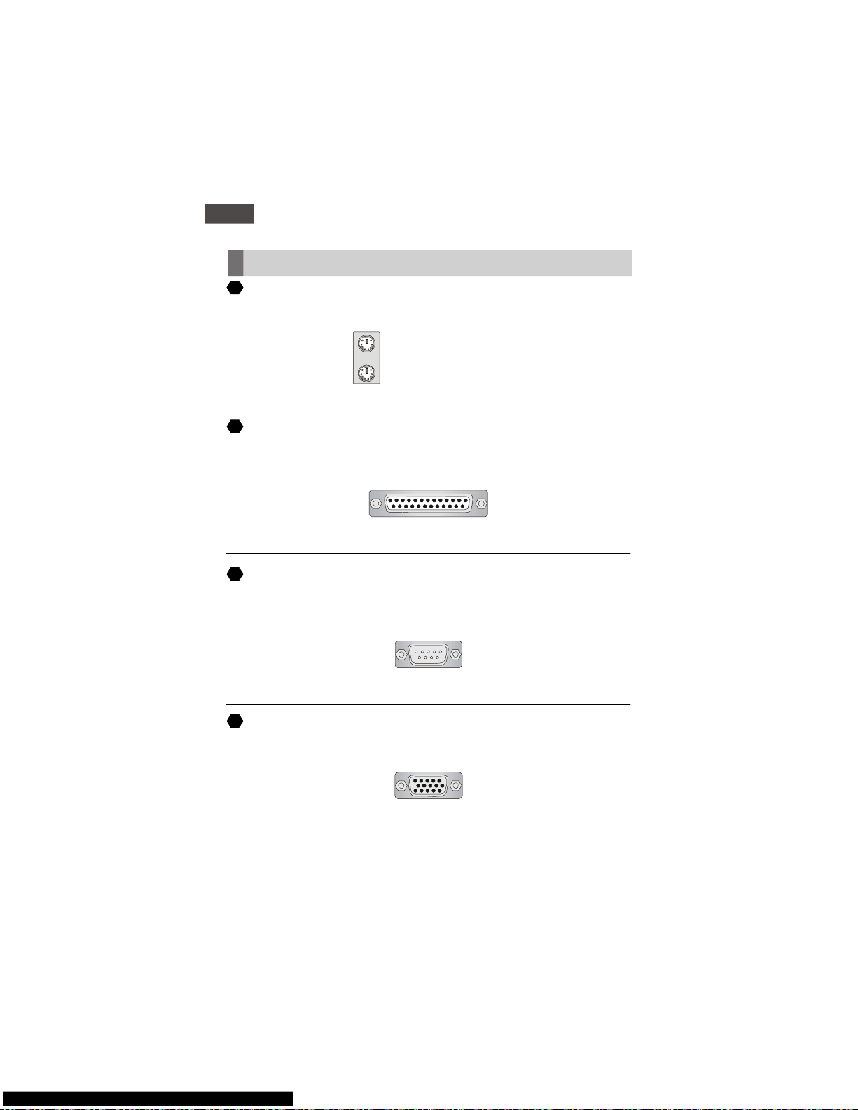
Back Panel
Mouse/Keyboard
The standard PS/2® mouse/keyboard DIN connector is for a PS/2® mouse/keyboard.
Parallel Port
A parallel port is a standard printer port that supports Enhanced Parallel Port (EPP) and
Extended Capabilities Parallel Port (ECP) mode.
Serial Port
The serial port is a 16550A high speed communications port that sends/ receives 16
bytes FIFOs. You can attach a serial mouse or other serial devices directly to the
connector.
VGA Port
The DB15-pin female connector is provided for monitor.
(9-Pin Male Connector)
1 5
6 9
A
B
C
D
PS/2 Mouse connector (Green/ 6-pin female)
PS/2 Keyboard connector (Purple/ 6-pin female)
13 1
1425
(25-pin female connector)
(15-Pin Female DIN Connector)
15
1115
Page 27
En-19
English
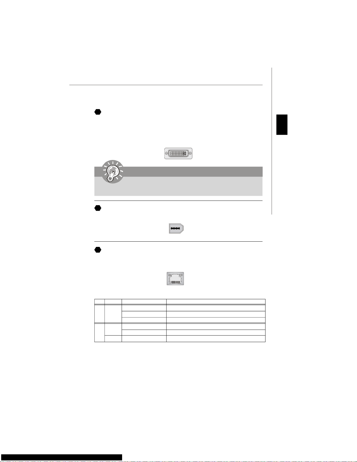
1394 Port
The IEEE1394 port on the back panel provides connection to IEEE1394 devices.
DVI Port
The DVI (Digital Visual Interface) connector allows you to connect an LCD monitor. It
provides a high-speed digital interconnection between the computer and its display
device. To connect an LCD monitor, simply plug your monitor cable into the DVI
connector, and make sure that the other end of the cable is properly connected to your
monitor (refer to your monitor manual for more information.)
1
24
17
8
Important
Please note that the DVI connector does not support connecting the D-Sub to
DVI converter.
LAN
The standard RJ-45 LAN jack is for connection to the Local Area Network (LAN). You can
connect a network cable to it.
LED Color LED State Condition
Off LAN link is not established.
Left Orange On (steady state) LAN link is established.
On (brighter & pulsing) The computer is communicating with another computer on the LAN.
Green Off 10 Mbit/sec data rate is selected.
Right On 100 Mbit/sec data rate is selected.
Orange On 1000 Mbit/sec data rate is selected.
E
F
G
Page 28
En-20
MS-7345 Mainboard
USB Port
The USB (Universal Serial Bus) port is for attaching USB devices such as keyboard,
mouse, or other USB-compatible devices.
Audio Port Connectors
These audio connectors are used for audio devices. You can differentiate the color of
the audio jacks for different audio sound effects.
Line-Out (Green) - Line Out, is a connector for speakers or headphones.
Line-In (Blue) - Line In / Side-Surround Out in 7.1 channel mode, is usedfor ex-
ternal CD player, tapeplayer or other audio devices.
MIC (Pink) - Mic In, is a connector for microphones.
CS-Out (Orange) - Center/ Subwoofer Out in 5.1/ 7.1 channel mode.
RS-Out (Black) - Rear-Surround Out in 4/ 5.1/ 7.1 channel mode.
SS-Out (Gray) - Side-Surround Out 7.1 channel mode.
Coaxial S/PDIF-out
This S/PDIF (Sony & Philips Digital Interconnect Format) connector is provided for
digital audio transmission to external speakers through a coaxial cable.
Optical S/PDIF-out
This S/PDIF (Sony & Philips Digital Interconnect Format) connector is provided for
digital audio transmission to external speakers through an optical fiber cable.
H
I
J
K
L
N
M
O
P
External SATA Port
This eSATA (External Serial ATA) port is used to connect the external SATA device. You
can also use the optional external SATA cable to connect SATA device and eSATA port.
Q
Page 29
En-21
English
LED Status Indicators
Name Status
LED1 Lights when system is power-on.
LED3 Lights when system is on standby mode.
LED11 Lights when PCI_E3 slot is functional.
LED12 Lights when PCI_E4 slot is functional.
LED13 Lights when PCI1 slot is functional.
LED14 Lights when PCI2 slot is functional.
LED15 Lights when PCI_E1 slot is functional.
LED16 Lights when PCI_E2 slot is functional.
LED14
LED13
LED12
LED16
LED15
LED11
LED3
LED1
LED20
LED10
LED19
LED9
LED18
LED8
LED17
LED7
Page 30
En-22
MS-7345 Mainboard
LED 7, 8, 9 ,10, 17, 18, 19, 20
These four LEDs allow users to identify system problems through 16 various combinations of LED signals.
BIOS Sign On
This will start showing information
about logo, processor brand name,
etc...
Testing Base and Extended Memory
Testing base memory from 240K to
640K and extended memory above
1MB using various patterns.
Assign Resources to all ISA.
Initializing Hard Drive Controller
This will initialize IDE drive and
controller.
Initializing Floppy Drive Controller
This will initialize Floppy Drive and
controller.
Boot Attempt
This will set low stack and boot via
INT 19h.
Operating System Booting
System Power ON
The D-LED will hang here if the
processor is damaged or not installed properly.
Initializing Keyboard Controller.
Testing VGA BIOS
This will start writing VGA sign-on
message to the screen.
Processor Initialization
This will show information regarding
the processor (like brand name, system bus, etc...)
Testing RTC (Real Time Clock)
Description
Red
Green
LED Signal
Description
LED Signal
Early Chipset Initialization
Memory Detection Test
Testing onboard memory size. The
D-LED will hang if the memory module is damaged or not installed
properly.
Decompressing BIOS image to RAM
for fast booting.
Initializing Video Interface
This will start detecting CPU clock,
checking type of video onboard. Then,
detect and initialize the video adapter.
LED20
LED10
LED19
LED9
LED18
LED8
LED17
LED7
Group1
Group2
Group3
Group4
Group4
Group3
Group2
Group1
Group4
Group3
Group2
Group1
Group4
Group3
Group2
Group1
Group4
Group3
Group2
Group1
Group4
Group3
Group2
Group1
Group4
Group3
Group2
Group1
Group4
Group3
Group2
Group1
Group4
Group3
Group2
Group1
Group4
Group3
Group2
Group1
Group4
Group3
Group2
Group1
Group4
Group3
Group2
Group1
Group4
Group3
Group2
Group1
Group4
Group3
Group2
Group1
Group4
Group3
Group2
Group1
Group4
Group3
Group2
Group1
Group4
Group3
Group2
Group1
Page 31

En-23
English
BIOS Setup
This chapter provides basic information on the BIOS Setup program and allows you to
configure the system for optimum use. You may need to run the Setup program when:
* An error message appears on the screen during the system booting up, and requests
you to run BIOS SETUP.
* You want to change the default settings for customized features.
Important
1.The items under each BIOS category described in this chapter are under continuous update for better system performance. Therefore, the description may
be slightly different from the latest BIOS and should be held for reference only.
2.Upon boot-up, the 1st line appearing after the memory count is the BIOS
version. It is usually in the format:
A7345IMS V1.0 011507 where:
1st digit refers to BIOS maker as A = AMI, W = AWARD, and P = PHOENIX.
2nd - 5th digit refers to the model number.
6th refers to the Chipset vender as A = ATi, I = Intel, V = VIA, N = Nvidia, U = ULi.
7th - 8th digit refers to the customer as MS = all standard customers.
V1.0 refers to the BIOS version.
011507 refers to the date this BIOS was released.
Page 32

En-24
MS-7345 Mainboard
Entering Setup
Power on the computer and the system will start POST (Power On Self Test) process.
When the message below appears on the screen, press <DEL> key to enter Setup.
Press DEL to enter SETUP
If the message disappears before you respond and you still wish to enter Setup, restart
the system by turning it OFF and On or pressing the RESET button. You may also restart
the system by simultaneously pressing <Ctrl>, <Alt>, and <Delete> keys.
Getting Help
After entering the Setup menu, the first menu you will see is the Main Menu.
Main Menu
The main menu lists the setup functions you can make changes to. You can use the
arrow keys (↑↓ ) to select the item. The on-line description of the highlighted setup
function is displayed at the bottom of the screen.
Sub-Menu
If you find a right pointer symbol (as shown in the right view)
appears to the left of certain fields that means a sub-menu
containing additional options can be launched from this
field. You can use control keys (↑↓ ) to highlight the field
and press <Enter> to call up the sub-menu. Then you can
use the control keys to enter values and move from field to field within a sub-menu. If
you want to return to the main menu, just press <Esc >.
General Help <F1>
The BIOS setup program provides a General Help screen. You can call up this screen
from any menu by simply pressing <F1>. The Help screen lists the appropriate keys to
use and the possible selections for the highlighted item. Press <Esc> to exit the Help
screen.
Page 33

En-25
English
Standard CMOS Features
Use this menu for basic system configurations, such as time, date etc.
Advanced BIOS Features
Use this menu to setup the items of special enhanced features.
Integrated Peripherals
Use this menu to specify your settings for integrated peripherals.
Power Management Features
Use this menu to specify your settings for power management.
PNP/PCI Configurations
This entry appears if your system supports PnP/PCI.
H/W Monitor
This entry shows your PC health status.
Cell Menu
Use this menu to specify your settings for fequency/voltage control and overclocking.
Load Fail-Safe Defaults
Use this menu to load the default values set by the BIOS vendor for stable system
performance.
Load Optimized Defaults
Use this menu to load the default values set by the mainboard manufacturer specifically
for optimal performance of themainboard.
BIOS Setting Password
Use this menu to set the Password.
Save & Exit Setup
Save changes to CMOS and exit setup.
Exit Without Saving
Abandon all changes and exit setup.
The Main Menu
Once you enter AMI® or AWARD® BIOS CMOS Setup Utility, the Main Menu will appear
on the screen. The Main Menu allows you to select from ten setup functions and two exit
choices. Use arrow keys to select among the items and press <Enter> to accept or enter
the sub-menu.
Page 34
En-26
MS-7345 Mainboard
When enter the BIOS Setup utility, follow the processes below for general use.
1. Load Optimized Defaults : Use control keys (↑↓ ) to highlight the Load Optimized
Defaults field and press <Enter> , a message as below appears:
Press [Ok] to load the default settings for optimal system performance.
2. Setup Date/ Time : Select the Standard CMOS Features and press <Enter> to enter
the Standard CMOS Features-menu. Adjust the Date, Time fields.
3. Save & Exit Setup : Use control keys (↑↓ ) to highlight the Save & Exit Setup field
and press <Enter> , a message as below appears:
Press [Ok] to save the configurations and exit BIOS Setup utility.
Important
The configuration above are for general use only. If you need the detailed
settings of BIOS, please see the manual in English version on MSI website.
Page 35
En-27
English
Software Information
Take out the Driver/Utility CD that is included in the mainboard package, and place it
into the CD-ROM driver. The installation will auto-run, simply click the driver or utiltiy
and follow the pop-up screen to complete the installation. The Driver/Utility CD contains the:
Driver menu - The Driver menu shows the available drivers. Install the driver by your
desire and to activate the device.
Utility menu - The Utility menu shows the software applications that the mainboard
supports.
WebSite menu- The WebSite menu shows the necessary websites.
Important
Please visit the MSI website to get the latest drivers and BIOS for better system
performance.
Page 36

De-1
Deutsch
P35 Platinum
Benutzerhandbuch
Deutsch
Page 37

De-2
MS-7345 Mainboard
Spezifikationen
Prozessoren
- Unterstützt Intel® Core 2 Quad/Duo/Pentium/Celeron
Prozessoren für Sockel LGA775
- Unterstützt Intel® Yorkfield (Quad-Core), Wolfdale (Dual-Core)
und zukünftige Intel Prozessoren mit einem FSB von 1333MHz
und Sockel LGA775
(Weitere CPU Informationen finden Sie unter http://global.msi.com.
tw/index.php?func=cpuform)
FSB (Front-Side-Bus)
- 1333/ 1066/ 800 MHz
Chipsatz
- North-Bridge: Intel® P35 Chipsatz
- South-Bridge: Intel® ICH9R Chipsatz
Speicher
- DDR2 800/667 SDRAM (max. 8GB)
- 4 DDR2 DIMMs (240Pin / 1.8V)
(Weitere Informationen zu kompatiblen Speichermodulen finden
Sie unter http://global.msi.com.tw/index.php?func=testreport)
LAN
- Unterstützt PCIE LAN 10/100/1000 Fast Ethernet über Realtek
8111B
Audio
- Onboard Soundchip Realtek® ALC888/ALC888T
- 8-Kanal Audio-Ausgang mit “Jack Sensing” Funktion (aut.
Erkennen der Anschlussgeräte)
- Erfüllt die Spezifikation Azalia1.0
- Zertifiziert für das Microsoft Vista Premium Betriebssystem
- Unterstützt VoIP Card (nur für ALC888T)
IDE
- 1 IDE Port über Marvell 88SE6111
- Unterstützt Betrieb mit Ultra DMA 66/100/133
- Unterstützt PIO, Bus Mastering
SATA
- 4 SATAII Ports mit 2 eSATA über ICH9R Southbridge
- 1 SATA II Port über Marvell 88SE6111
- Unterstützt Datenübertragungsraten von bis zu 300 MB/s
Page 38

De-3
Deutsch
RAID
- Unterstützt Intel Martix Storage Technologie (AHCI + RAID 0/1/5/
10) über ICH9R Southbridge
1394
- Unterstützt 1394 über VIA VT6308
Diskette
- 1 Disketten Anschluss
- Unterstützt 1 Diskettenlaufwerk mit 360KB, 720KB, 1.2MB, 1.
44MB und 2.88MB
Anschlüsse
Hintere Ein-/ und Ausgänge
- 1 PS/2 Mausanschluss
- 1 PS/2 Tastaturanschluss
- 2 eSATA Schnittstellen (unterstützt “Command Based Port
Multipliers”)
- 6 USB 2.0 Anschlüsse
- 1 LAN Buchse (10/100/1000)
- 6 Audiobuchsen
- 1 1394 Anschluss (optional)
- 1 optischer S/PDIF-Ausgang (optional)
On-Board Stiftleiste/ Anschlüsse
- 3 USB 2.0 Stiftleisten
- 1 1394 Stiftleiste (optional)
- 1 Gehäusekontaktschalter
- 1 SPDIF-Ausgang Stiftleiste
- 1 CD-Stiftleiste für Audio Eingang
- 2 Hardware Overklokken FSB-jumper
- 1 Audio Stiftleiste für Gehäuse Audio Ein-/ Ausgänge
- 1 Serielle Schnittstelle
Schnittstellen
- 1 PCI Express x16 Schnittstelle
- 2 PCI Express x1 Schnittstellen
- 1 PCI Express x4 Schnittstelle
- 2 PCI Schnittstellen
- Unterstützt 3.3V/ 5V PCI Bus Interface
Form Faktor
- ATX (30.5cm X 24.5cm)
Montage
- 9 Montagebohrungen
Page 39
De-4
MS-7345 Mainboard
Übersicht Eingenschaften der P35 Platinum Mainboard Serie
(MS-7345 v1.X)
1
De-5
4
De-9
3
De-7
22
De-15
4
De-9
6
De-9
15
De-12
7
De-10
21
De-15
8 De-10
10
De-11
4
De-9
4
De-9
9
De-10
11
De-11
5
De-9
12
De-1114De-12
17
De-13
28
De-17
29
De-17
19
De-13
4
De-9
25
De-16
26
De-16
A
De-18
A
De-18
H De-20
F
De-19
P
De-20
G
De-19
H
De-20
Q
De-20
K De-20
L De-20
N De-20
De-20
I
J
De-20
M De-20
13 De-12
Page 40

De-5
Deutsch
Hauptprozessor: CPU
Das Mainboard unterstützt Intel® Prozessoren und verwendet hierfür einen CPU
Sockel mit der Bezeichnung Sockel-775, um das Einsetzen der CPU zu erleichtern.
Verfügen Sie über keinen Kühler, setzen Sie sich bitte mit Ihrem Händler in Verbindung,
um einen solchen zu erwerben und danach zu installieren, bevor Sie Ihren Computer
anschalten.
Um die neuesten Informationen zu unterstützten Prozessoren zu erhalten, besuchen
Sie bitte http://global.msi.com.tw/index.php?func=cpuform
1
Wichtig
Überhitzung
Überhitzung beschädigt die CPU und das System nachhaltig, stellen Sie stets
eine korrekte Funktionsweise des CPU Kühlers sicher, um die CPU vor
Überhitzung zu schützen. Überprüfen Sie eine gleichmäßige Schicht der
thermischen Paste (oder thermischen Klebeandes) zwischen der CPU und dem
Kühlblech anwenden, um Wärmeableitung zu erhöhen.
CPU Wechsel
Stellen Sie vor einem Wechsel des Prozessors stets sicher, dass das ATX
Netzteil ausgeschaltet und der Netzstecker gezogen ist, um die Unversehrtheit
der CPU zu gewährleisten.
Übertakten
Dieses Motherboard wurde so entworfen, dass es Übertakten unterstützt. Stellen
Sie jedoch bitte sicher, dass die betroffenen Komponenten mit den abweichenden
Einstellungen während des Übertaktens zurecht kommen. Von jedem Versuch des
Betriebes außerhalb der Produktspezifikationen kann nur abgeraten werden. Wir
übernehmen keinerlei Garantie für die Schäden und Risiken, die aus
unzulässigem oder Betrieb jenseits der Produktspezifikationen resultieren.
Page 41
De-6
MS-7345 Mainboard
CPU & Kühler Einbau für Sockel 775
1. Der CPU-Sockel besitzt zum Schutz eine Plastikabdeckung. Lassen
Sie vor der Installtion diese Schutzkappe auf dem Sockel um Schäden
zu vermeiden.
2. Entfernen Sie zuerst die Schutzkappe wie abgebildet in Pfeilrichtung.
3. Sie sehen jetzt die Pins des Sockels.
4. Öffnen Sie den Sockelverschlusshebel.
5. Klappen Sie den Hebel ganz auf und öffnen Sie die
Metallverschlussklappe.
6. Vergewissem Sie sich anhand der Justiermarkierungen und dem
gelben Dreieck, daß die CPU in der korrekten Position ist. Setzen
Sie anschließend die CPU in den Sockel.
7. Begutachten Sie, ob die CPU richtig im Sockel sitzt. Falls nicht,
zeihen Sie die CPU durch eine rein vertikale Bewegung wieder
heraus. Versuchen Sie es erneut.
8. Schließen Sie die Abdeckung des Sockels.
9. Drücken Sie den Verschlusshebel mit leichtem Druck nach unten
und arretieren Sie den Hebel unter dem Rückhaltenhaken des CPU-
Sockels.
10.Frühren Sie den CPU-Kühler über den CPU-Sockel und positionieren
Sie die Arretierungsstifte des Kühlers über die dafür vorgesehenen
Löcher des Mainboards. Drücken Sie den Kühler nach unten bis die
Stifte in den Löchern eingerastet.
11.Drücken Sie die vier Stifte nach unten um den Kühler zu arretieren.
Drehen Sie dann jeweils den Verschluss der Stifte (Richtung ist auf
dem Kühler markiert) .
12.Drehen Sie das Mainboard um und vergewissern Sie sich, dass das der
Kühler korrekt installiert ist.
alignment key
Wichtig
1. Prüfen Sie die Status der CPU im BIOS.
2. Wenn keine CPU installiert ist, schützen Sie immer den CPU-Sockel durch die
Plastikabdeckung.
3. Die Mainboard Fotos, die in diesem Abschnitt gezeigt werden, sind für Demonstration der CPU/ Kühler Installation. Das Aussehen Ihres mainboard kann
abhangig von dem Modell schwanken, das Sie kaufen.
Page 42

De-7
Deutsch
Speicher
DDR
Spezifikation : 184-Pin, 2.5v.
Bestimmung Einkanalbetrieb : All DIMM Slots sind GRÜNE Farbe.
Bestimmung Zweikanalbetrieb : Die DIMM Slot(s) des Kanals A sind in GRÜN gehalten.
Die DIMM Slot(s) des Kanals B sind LILA.
DDR2
Spezifikation : 240-Pin, 1.8V.
Bestimmung Einkanalbetrieb : Alle DIMM Slots sind GRÜNE Farbe.
Bestimmung Zweikanalbetrieb : Die DIMM Slot(s) des Kanals A sind in GRÜN gehalten.
Die DIMM Slot(s) des Kanals B sind ORANGE.
64x2=128 Pin 56x2=112 Pin
40x2=80 Pin 52x2=104 Pin
2
3
Wichtig
- DDR2 und DDR können nicht untereinander getauscht werden und der Standard
DDR2 ist nicht rückwärtskompatibel, installieren Sie DDR2 Speichermodule stets
in DDR2 DIMM Slots und DDR2 Speichermodule stets in DDR2 DIMM Slots.
- Stellen Sie im Zweikanalbetrieb bitte sicher, dass Sie Module des gleichen
Typs und identischer Speicherdichte in den DDR DIMM Slots unterschiedlicher
Kanäle verwenden.
- Um einen sicheren Systemstart zu gewährleisten, bestücken Sie immer DIMM 1
zuerst.
Page 43
De-8
MS-7345 Mainboard
Vorgehensweise beim Einbau von Speicher Modulen
Sie finden Kerbe und Stromführung (Volt) sowohl an DDR als auch DDR2 Modulen.
Befolgen Sie die folgenden Einbauhinweise, um die DDR/ DDR2 Module
ordnungsgemäß einzusetzen.
1.Diese Speichermodulen haben nur eine Kerbe in der Mitte des Moduls. Sie passen
nur in einer Richtung in den Sockel.
2.Setzen Sie den DIMM- Speicherbaustein senkrecht in den DIMM- Sockel, dann
drücken Sie ihn hinein, bis die goldenen Kontakte tief im DIMM Sockel sitzen.
3.Die Plastikklammern an den Seiten des DIMM- Sockels schließen sich automatisch.
Wichtig
Sie können den goldenen Finger kaum sehen, wenn das Speichermodule richtig
im DIMM Steckplatz eingesetzt wird.
Volt
Notch
Page 44

De-9
Deutsch
Anschlüsse, Steckbrücken und Slots
Anschluss des Diskettenlaufwerks
Diese Anschluss unterstützt ein Diskettenlaufwerke mit 360KB, 720KB, 1.2MB, 1.44MB
oder 2.88MB Kapazität.
5
Stromanschlüsse für Lüfter
Die Anschlüsseunterstützen aktive Systemlüfter mit + 12V. CPU FAN kann Smart FAN
Funktion unterstützen. Wenn Sie den Anschluss herstellen, sollten Sie immer darauf
achten, dass der rote Draht der positive Pol ist, und mit +12V verbunden werden sollte,
der schwarze Draht ist der Erdkontakt und sollte mit GND verbunden werden. Ist Ihr
Mainboard mit einem Chipsatz zur Überwachung der Systemhardware versehen, dann
brauchen Sie einen speziellen Lüfter mit Tacho, um die Vorteile der Steuerung des
CPU Lüfters zu nutzen.
SYS FAN/ NB FAN/POWER FAN (System-,
Northbridge- und Netzteillüfter)
SENSOR or NC
+12V
GND
4
IDE Anschluss
An diesen Anschluss können IDE Festplatten, optische Laufwerke (CD/DVD-Brenner, ...)
und andere Geräte betrieben werden.
6
CPU FAN
(Lüfter)
SENSOR
+12V
GND
Control
Wichtig
1.Bitte informieren Sie sich auf der offiziellen Website vom Prozessor über
empfohlene CPU Kühler oder fragen Sie Ihren Händler nach einem geeigneten
Lüfter.
2.CPUFAN unterstützt die Lüfterkontrolle. Sie künnen das Utility Dual Core
Center installieren, welches automatisch die Geschwindigkeit des CPU Lüfters
in Abhängigkeit von der CPU Temperatur steuert.
3. CPUFAN kann die Lüfter mit drei- und vierpolige Stecker unterstützen.
Wichtig
Verbinden Sie zwei Laufwerke über ein Kabel, müssen Sie das zweite Laufwerk
im Slave-Modus konfigurieren, indem Sie entsprechend den Jumper setzen.
Entnehmen Sie bitte die Anweisungen zum Setzen des Jumpers der
Dokumentation der IDE Geräte, die der Festplattenhersteller zur Verfügung
stellt.
Page 45

De-10
MS-7345 Mainboard
Frontpanel Anschlüsse
Diese Anschlüsse sind für das Frontpanel dienen zum Anschluss der Schalter und LEDs
des Frontpaneels. JFP1 erfüllt die Anforderungen des “Intel Front Panel I/O Connectivity Design Guide“.
8
Serial ATA Anschluss
An diesen Anschluss können Sie serielle Geräte mit einer Geschwindigkeit von 150
Mbit/s und/oder 300Mbit/s betrieben werden (Abhängig vom Mainboard Chipsatz). Pro
Anschluss kann ein S-ATA Gerät angeschlossen werden.
7
Wichtig
Bitte falten Sie das Serial ATA Kabel nicht in einem Winkel von 90 Grad, da
dies zu Datenverlusten während der Datenübertragung führt.
IEEE1394 Anschluss (Grün)
Dieser Anschluss erlaubt Ihren,die Vorrichtung IEEE1394 über ein externes IEEE1394
Slotblech anzuschließen.
9
IEEE1394 Slotblech
(Optional)
JFP2
7
8
Power LED
Speaker
12
JFP1
1
2
910
HDD
LED
Reset
Switch
Power
LED
Power
Switch
1
2
9
10
TPA-
Ground
TPB-
Cable power
Ground
TPA+
Ground
TPB+
Cable power
Key (no pin)
Page 46

De-11
Deutsch
Audioanschluss des Frontpanels (Azalia Spec)
Dieser Anschluss ermöglicht den Anschluss von Audioein- und -ausgängen eines
Frontpanels. Der Anschluss entspricht den Richtlinien des “ Intel® Front Panel I/O Connectivity Design Guide”.
12
S/PDIF-Out Anschluss (Optional, für HDMI Grafikkarten)
Der Anschluss S/PDIF (Sony & Philips Digital Interconnect Format) überträgt digitale
Audiosignale vom Mainboard zur HDMI Grafikkarte.
11
USB Vorderanschluss (Gelb)
Dieser Anschluss entspricht den Richtlinien des Intel® I/O Connectivity Design Guide, ist
bestens geeignet, Hochgeschwindigkeits- USB- Peripheriegeräte anzuschließen, wie z.
B. USB Festplattenlaufwerke, Digitalkameras, MP3-Player, Drucker, Modems und
ähnliches.
10
Bitte beachten Sie, dass Sie die mit VCC (Stromführende Leitung) und GND
(Erdleitung) bezeichneten Pins korrekt verbinden müssen, ansonsten kann es zu
Schäden kommen.
Wichtig
USB 2.0 Slotblech
(Optional)
SPDIFO
GND
1
2
USBOC
10
1
2
VCC
USB0-
USB0+
GND
Key (no pin)
VCC
USB1-
USB1+
GND
9
1
2
9
10
MIC _L
MIC _R
LINE out_R
Front_JD
LINE out_L
Ground
Presence#
MIC_JD
NC(No pin)
LINE out_JD
Page 47

De-12
MS-7345 Mainboard
CD- Eingang
Dieser Anschluss wird für externen Audioeingang zur Verfügung gestellt.
Gehäusekontaktanschluss
Dieser Anschluss wird mit einem Kontaktschalter verbunden. Wird das Gehäuse geöffnet,
wird der Schalter geschlossen und das System zeichnet dies auf und gibt auf dem
Bildschirm eine Warnung aus. Um die Warnmeldung zu löschen, muss das BIOS
aufgerufen und die Aufzeichnung gelöscht werden.
GND R
L
15
13
14
1
2
CINTRU
GND
Hardware Übertaktung FSB Steckbrücke: JB1, JB2 (optional)
Übertaken der FSB, um die Prozessorfrequenz erhöhen durch das Andern die Steckbrücke
JB1 und JB2. Folgen Sie die Anleitungen zur Einstellung FSB.
1
266 MHz
1
3
200 MHz
1
3
JB1 JB2
333 MHz
1
3
Wichtig
Stellen bitte Sie sicher, dass Sie schalten die System aus bevor Sie die
Steckbrücke ändern.
Page 48
De-13
Deutsch
Infrarotmodul Stifleiste
Gestattet zu jeder Zeit den Anschluss eines Infrarotmoduls und entspricht den Richtlinien
des Intel® Front Panel I/O Connectivity Design Guide. Sie müssen im BIOS die
notwendigen Einstellungen vornehmen, um die IR Funktion nutzen zu können.
Serielle Schnittstelle
Bei der Anschluss handelt es sich um eine 16550A Hochgeschwindigkeitskommunikationsschnittstelle, die 16 Bytes FIFOs sendet/empfängt. An den Stecker können Sie direkt
eine Serielles Gerät anschließen.
TV- Ausgang
Der TV- Ausgang dient zum Anschluss eines Slotbleches mit TV- Ausgang. Das Slotblech
bietet mehrere Arten von TV Ausgängen. Wählen Sie einen geeigneten, um ein
Fernsehgerät anzuschließen.
6
5
2
1
NC
VCC5
IRTX
NC
Ground
IRRX
16
17
18
3
1 4
Ground
Yout
Cout
COMP or CVBS
Ground (5)
1
5
6
DCD
SIN
SOUT
DTR
Ground
DSR
RTS
CTS
RI (9)
VoIP Karte Anschluss
Der Anschluss verbindet Ihre Voice over IP (VoIP) Karte mit Ihrem Mainboard. Eine
Funktionsbeschreibung und weitere nützliche Informationen finden Sie im Handbuch
der VoIP Karte.
19
Page 49

De-14
MS-7345 Mainboard
D-Bracket™ 2 Anschluss
Dieser Anschluss ist, damit Sie an das D-Bracket™ 2 anschließen, das vier LED und USB
Tore integriert. Es erlaubt Benutzern, System Probleme durch 16 verschiedene
Kombinationen der LED Signale zu kennzeichnen.
20
BIOS Anmeldung
Zeigt informationen, Logo,
Prozessorhersteller, etc...
Test des Basis- und erweiterten
Speichers - Test des Basisspeichers
von 240K bis 640K und des erweiterten
Speichers über 1MB mit unterschiedlichen Mustern.
Zuweisung der Resourcen an alle
ISA Komponenten
Initialisierung Festplattenkontroller
Initialisiert die Festplatte und den
Kontroller
Initialisierung des Diskettenkontrollers.
Initialisiert das Diskettenlaufwerk
und den Kontroller.
Versuch hoch zu fahren.
Setzt den niedrigen Stapel und
booted über INT 19h.
Hochfahren des Betriebssystems
System AN
Die D-LED bleibt hier stehen, wenn
der Prozessor beschädigt ist oder
nicht richtig installiert.
Initialisierung Tastatur Kontroller.
Test VGA BIOS
Hier wird die VGA- Anmeldung am
Bildschirm angezeigt.
Prozessorinitialisierung
Zeigt Informationen zum Prozessor
(wie Name der Marke, Systembus,
etc...)
Test der Echtzeituhr (RTC - Real
Time Clock)
Description
Rot
Grün
LED Signal
1 2
3 4
1 2
3 4
1 2
3 4
1 2
3 4
1 2
3 4
1 2
3 4
1 2
3 4
1 2
3 4
Description
LED Signal
1 2
3 4
1 2
3 4
1 2
3 4
1 2
3 4
1 2
3 4
1 2
3 4
1 2
3 4
1 2
3 4
Frühe Initialisierung des Chipsatzes
Speichertest - Test der Größe des
Speichers onboard. Die D-LED
bleibt bei beschädigtem oder
fehlerhaft eingesetztem Modul
hängen.
Entpacken des BIOS ins RAM zum
schnellen Hochfahren.
Initialisierung Video Schnittstelle startet Ermittlung CPU Takt,
überprüfing Video onboard. Danach
Erkennung und Initialisierung der
Grafiklösung.
D-Bracket™ 2
(Optional)
Verbindung zum
D-Bracket™ 2
Anschluss
Verbindung zur USB
Stiftleiste
1
9
2
10
DBG1
DBG2
DBG3
DBG4
Key
DBR1
DBR2
DBR3
DBR4
NC
Page 50
De-15
Deutsch
Schalter zur CMOS Wiederherstellung
Der Onboard CMOS Speicher (BIOS), enthält Grundinformationen sowie erweite
Eistellungen des Mainboards.
Der CMOS Speicher wird über eine Betterie mit Strom versotgt, damit die Daten nach
Abschalten des PC-systems erhalten bleiben. Wieterhin sind Informationen für den
Start des Systems in dem Speicher hinterlegt. Sollten Sie Fehlermeldungen während
des Startvorganges erhalten, kann ein Zurücksetzen des CMOS Speichers in den
ursprünglichen Werkszustand helfen. Drücken Sie dazu leicht den Schalter.
Zusätzlicher Hinweis Stromversorgung
Bevor Sie eine Verbindung mit den Stromanschlüssen herstellen, stellen Sie immer
sicher, dass alle Komponenten ordnungsgemäß eingebaut sind, um jegliche Schäden
auszuschließen. Alle Stromanschlüsse auf dem Mainboard müssen mit einem ATX Netzteil
verbunden werden und müssen gemeinsam den stabilen Betrieb des Mainboards sicher
stellen.
ATX 24-Pin Stromanschluss
Hier können Sie ein ATX 24-Pin Netzteil anschließen. Wenn Sie die Verbindung
herstellen, stellen Sie sicher, dass der Stecker in der korrekten Ausrichtung eingesteckt
wird und die Pins ausgerichtet sind. Drücken Sie dann den Netzteilstecker fest in den
Steckersockel.
Sie können auch ein 20-Pin ATX Netzteil verwenden, wenn Sie möchten. Wenn Sie ein
20-Pin ATX Netzteil einsetzen möchten, stecken Sie bitte Ihr Netzteil beginnend bei
den PinS 1 und 13 ein.
22
1
12
24
13
+3.3V
+3.3V
GND
+5V
GND
+5V
GND
PWR OK
5VSB
+12V
+12V
+3.3V
GND
+5V
+5V
+5V
NC
GND
GND
GND
PS-ON#
GND
-12V
+3.3V
21
Wichtig
Stellen Sie sicher, dass das System ausgeschaltet ist, bover Sie den CMOS
Speicher in den Werkszustand zurücksetzen.
Page 51

De-16
MS-7345 Mainboard
NV SLI Steckplatz
Mit diesem Steckplatz (de-) aktivieren Sie die SLI Technologie Funktion. Achten Sie
dazu auf die Pfeilrichtung auf der SLI Karten. Die SLI Karte ist sich im Lieferumfang
Ihres MSI SLI Mainboards enthalten.
ATX 12V Stromanschluss (2x2-Pin)
Dieser 12V Stromanschluss wird verwendet, um die CPU mit Strom zu versorgen.
ATX 12V Stromanschluss (2x4-Pin)
Dieser 12V Stromanschluss wird verwendet, um die CPU mit Strom zu versorgen.
ATX 12V Stromanschluss (1x4-Pin)
Dieser 12V Stromanschluss wird verwendet, um die Grafikkarte mit Strom zu versorgen.
1342
GND
12V
GND
12V
4
2
1
3
5V
GND
GND
12V
ATX 20-Pin Stromanschluss
Hier können Sie ein ATX 20-Pin Netzteil anschließen. Wenn Sie die Verbindung
herstellen, stellen Sie sicher, dass der Stecker in der korrekten Ausrichtung eingesteckt
wird und die Pins ausgerichtet sind. Drücken Sie dann den Netzteilstecker fest in den
Steckersockel.
23
24
25
26
8
4
1
5
GND
+12V
27
1
10 20
11
3.3V
3.3V
GND
5V
GND5VGND
PWR OK
5VSB
12V 5V
5V
-5V
GND
GND
GND
PS-ON
GND
-12V
3.3V
Page 52

De-17
Deutsch
PCI Express Slot (x16/ x4/ x1)
Der PCI Express Slot unterstutzt die PCI Express Schnittstelle Erweiterungskarten.
Der PCI Express x 16 unterstutzt die Datenubertragunsraten von bis zu 4.0 GB/s.
Der PCI Express x 8 unterstutzt die Datenubertragunsraten von bis zu 2.0 GB/s.
Der PCI Express x 4 unterstutzt die Datenubertragunsraten von bis zu 1.0 GB/s.
Der PCI Express x 1 unterstutzt die Datenubertragunsraten von bis zu 250 MB/s.
PCI Express x 16 Slot
PCI Express x 4 Slot
PCI Express x 1 Slot
PCI (Peripheral Component Interconnect) Slot
Die PCI Steckplätze unterstützt LAN Karte, SCSI Karte, USB Karte und andere
Zusatzkarten cards,die mit PCI Spezifikationen übereinstimmen.
AGP (Accelerated Graphics Port) Slot
Der AGP Steckplatz gestattet Ihnen den Einsatz von AGP Grafikkarten. AGP ist eine
Schnittstellenspezifikation, diegemäß den Anforderungen von 3D Grafiken an den
Datendurchsatz entwickelt wurde. Mit ihr hat die direkte Anbindung des Grafikkontrollers
an den Hauptspeicher mit mit 66MHz getakteten 32-Bit Kanal Einzug gehalten.
28
29
30
Wichtig
Stellen Sie vor dem Einsetzen oder Entnehmen von Karten sicher, dass Sie den
Netzstecker gezogen haben. Studieren Sie bitte die Anleitung zur
Erweiterungskarte, um jede notwendige Hard - oder Softwareeinstellung für die
Erweiterungskarte vorzunehmen, sei es an Steckbrücken (“Jumpern”), Schaltern
oder im BIOS.
Page 53

De-18
MS-7345 Mainboard
Hinteres Anschlusspanel
Maus-/Tastatur
Die Standard PS/2® Maus/Tastatur Stecker Mini DIN ist für eine PS/2® Maus/Tastatur .
Parallele Schnittstelle
Die Parallele Schnittstelle ist eine Standard Druckerschnittstelle, die ebenso als Enhanced Parallel Port (EPP) und als Extended Capabilities Parallel Port (ECP) betrieben
werden kann.
Serielle Schnittstelle
Bei der Seriellen Schnittstelle handelt es sich um eine 16550A Hochgeschwindigkeitskommunikationsschnittstelle, die 16 Bytes FIFOs sendet/empfängt. An den Stecker können
Sie direkt eine Serielle Maus oder ein anderes Serielles Gerät anschließen.
VGA Anschluss
Die DB 15-Pin Buchse dient zum Anschluss eines VGA Monitors.
(15-Pin DIN Buchse)
15
1115
A
B
C
D
PS/2 Mausanschluss (Grün/ 6-Pin Buchse)
PS/2 Tastaturanschluss (Lila/ 6-Pin Buchse)
13 1
1425
(25-Pin Centronics Anschlussbuchse)
(9-Pin DIN Steckeranschluss)
1 5
6 9
Page 54

De-19
Deutsch
1394 Port
Das IEEE 1394 Port auf der hintere Anschlusspanel zu den Vorrichtungen IEEE1394.
DVI Port
Der DVI (Digital Visual Interface) Anschluss erlaubt Ihnen, einen LCD Monitor
anzuschließen. Es stellt eine digitale Hochgeschwindigkeitsverbindung zwischem dem
Computer und dem Bildschirm her. Um einen LCD Monitor anzuschließen, verbinden
Sie dessen Stecker einfach mit dem DVI Anschluss des Mainboards und stellen Sie
sicher, dass das andere Ende des Kabels ordnungsgemäß mit dem Monitor verbunden
ist.(Weitere Informationen können Sie dem Handbuch Ihres Monitors entnehmen.)
1
24
17
8
Wichtig
Bitte beachten Sie, dass dieser DVI Anschluss keinen D-Sub Anschluss über
einen DVI Konverter zulässt.
LAN
Die Standard RJ-45 Buchse ist für Anschlus zum an ein Lokales Netzwerk (Local Area
Network - LAN). Hier kann ein Netzwerkkabel angeschlossen werden.
LED Farbe LED Status Zustand
Aus Keine Verbindung mit dem LAN.
Links Orange An (Dauerleuchten) Verbindung mit dem LAN.
An (heller & pulsierend) Der Computer kommuniziert mit einem anderen Rechner im LAN.
Grün Aus Gewählte Datenrate 10 MBit/s.
Rechts An Gewählte Datenrate 100 MBit/s.
Orange An Gewählte Datenrate 1000 MBit/s.
G
F
E
Page 55

De-20
MS-7345 Mainboard
USB Port
Dieser USB (Universal Serial Bus) Anschluss zum direkten Anschluss von USB- Geräten,
wie etwa Tastatur, Maus oder weiterer USB-kompatibler Geräte.
Audioschnittstellen
Diese Audioanschlüsse werden im Zusammenspiel mit Audioein-/ ausgabegeräten
verwendet. Anhand der Farbe der Audiobuchsen kann man unterschiedliche
Verwendungen unterscheiden.
Line-Ausgang (Grün) - Line Ausgang, für Lautsprecher und Kopfhörer.
Line-Eingang (Blau) - Line Eingang / Seitliches Surroundsignal im 7.1 Kanalbetrieb,
kann für externe CD oder Kasettenspieler oder andere Audiogeräte verwendet werden.
MIK (Pink) - Mikrofon, für Mikrofoneingang.
CS-Ausgang (Orange) - Center-/ Subwooferausgang im 5.1/ 7.1 Kanalbetrieb.
RS-Ausgang (Schwarz) - Hinteres Surroundsignal im 4/ 5.1/ 7.1 Kanalbetrieb.
SS-Ausgang (Grau) - Seitlichen Surroundsignal im 7.1 Kanalbetrieb.
Koaxialer S/PDIF- Ausgang
Dieser S/PDIF (Sony & Philips Digital Interconnect Format) Ausgang dient als digitale
Schnittstelle zur Audioausgabe zur den externen Lautsprechern durch ein Koaxialkabel.
Optischer S/PDIF-Ausgang
Dieser S/PDIF (Sony & Philips Digital Interconnect Format) Ausgang dient als digitale
Schnittstelle zur Audioausgabezur den externen Lautsprechern durch ein optischen
Fasernkabel.
H
I
J
K
L
M
N
P
O
Externer eSATA Anschluss
Der eSATA (External Serial ATA) verbindet eSATA Geräte (z.B. externe Festplatten) mit
Ihrem Mainboard. Das Kabel zum Verbinden von Ihrem extermen eSATA Gerät ist
optional und nicht im lieferumfang enthalten.
Q
Page 56

De-21
Deutsch
LED Statusdikatoren
Name Status
LED1 Leicht, wenn das System aktiviert ist.
LED3 Leicht, wenn das System im Ruhemodus ist.
LED11 Leicht, wenn PCI_E3 Slot funktionell ist.
LED12 Leicht, wenn PCI_E4 Slot funktionell ist.
LED13 Leicht, wenn PCI1 Slot funktionell ist.
LED14 Leicht, wenn PCI2 Slot funktionell ist.
LED15 Leicht, wenn PCI_E1 Slot funktionell ist.
LED16 Leicht, wenn PCI_E2 Slot funktionell ist.
LED14
LED13
LED12
LED16
LED15
LED11
LED3
LED1
LED20
LED10
LED19
LED9
LED18
LED8
LED17
LED7
Page 57

De-22
MS-7345 Mainboard
LED 7, 8, 9 ,10, 17, 18, 19, 20
Es beinhaltet LEDs und ermöglicht es dem Anwender Probleme zu identifizieren, in
dem es 16 unterschiedliche Kombinationen von LED Signalen ausgibt.
BIOS Anmeldung
Zeigt informationen, Logo,
Prozessorhersteller, etc...
Test des Basis- und erweiterten
Speichers - Test des Basisspeichers
von 240K bis 640K und des erweiterten
Speichers über 1MB mit unterschiedlichen Mustern.
Zuweisung der Resourcen an alle
ISA Komponenten.
Initialisierung Festplattenkontroller
Initialisiert die Festplatte und den
Kontroller.
Initialisierung des Diskettenkontrollers.
Initialisiert das Diskettenlaufwerk
und den Kontroller.
Versuch hoch zu fahren.
Setzt den niedrigen Stapel und
booted über INT 19h.
Hochfahren des Betriebssystems
System AN
Die D-LED bleibt hier stehen, wenn
der Prozessor beschädigt ist oder
nicht richtig installiert.
Initialisierung Tastatur Kontroller.
Test VGA BIOS
Hier wird die VGA- Anmeldung am
Bildschirm angezeigt.
Prozessorinitialisierung
Zeigt Informationen zum Prozessor
(wie Name der Marke, Systembus,
etc...)
Test der Echtzeituhr (RTC - Real
Time Clock)
Beschreibung
Rot
Grün
LED Signal
Beschreibung
LED Signal
Frühe Initialisierung des Chipsatzes
Speichertest - Test der Größe des
Speichers onboard. Die D-LED
bleibt bei beschädigtem oder
fehlerhaft eingesetztem Modul
hängen.
Entpacken des BIOS ins RAM zum
schnellen Hochfahren.
Initialisierung Video Schnittstelle startet Ermittlung CPU Takt,
überprüfing Video onboard. Danach
Erkennung und Initialisierung der
Grafiklösung.
LED20
LED10
LED19
LED9
LED18
LED8
LED17
LED7
Gruppe1
Gruppe2
Gruppe3
Gruppe4
Gruppe4
Gruppe3
Gruppe2
Gruppe1
Gruppe4
Gruppe3
Gruppe2
Gruppe1
Gruppe4
Gruppe3
Gruppe2
Gruppe1
Gruppe4
Gruppe3
Gruppe2
Gruppe1
Gruppe4
Gruppe3
Gruppe2
Gruppe1
Gruppe4
Gruppe3
Gruppe2
Gruppe1
Gruppe4
Gruppe3
Gruppe2
Gruppe1
Gruppe4
Gruppe3
Gruppe2
Gruppe1
Gruppe4
Gruppe3
Gruppe2
Gruppe1
Gruppe4
Gruppe3
Gruppe2
Gruppe1
Gruppe4
Gruppe3
Gruppe2
Gruppe1
Gruppe4
Gruppe3
Gruppe2
Gruppe1
Gruppe4
Gruppe3
Gruppe2
Gruppe1
Gruppe4
Gruppe3
Gruppe2
Gruppe1
Gruppe4
Gruppe3
Gruppe2
Gruppe1
Gruppe4
Gruppe3
Gruppe2
Gruppe1
Page 58
De-23
Deutsch
BIOS Setup
Dieses Kapitel enthält Informationen über das BIOS Setup und ermöglicht es Ihnen, Ihr
System optimal auf Ihre Anforderungen einzustellen. Notwendigkeit zum Aufruf des
BIOS besteht, wenn:
* Während des Bootvorgangs des Systems eine Fehlermeldung erscheint und Sie zum
Aufruf des BIOS SETUP aufgefordert werden.
* Sie die Werkseinstellungen zugunsten individueller Einstellungen ändern wollen.
Wichtig
1. Die Menüpunkte jeder BIOS Kategorie, die in diesem Kapitel beschrieben
wird, werden permanent auf den neuesten Stand gebracht, um die
Systemleistung zu verbessern. Aus diesem Grunde kann die Beschreibung
geringfügig von der aktuellsten Version des BIOS abweichen und sollte
dementsprechend lediglich als Anhaltspunkt dienen.
2. Während des Hochfahrens, wird die BIOS Version in der ersten Zeile nach dem
Hochzählen des Speichers angezeigt, üblicherweise im Format dieses Beispiels:
A7345IMS V1.0 011507 wobei:
Die erste Stellen den BIOS-Hersteller bezeichnet, dabei gilt A = AMI, W = AWARD,
und P = PHOENIX.
2te - 5te Stelle bezeichnet die Modelnummer.
6te Stelle bezeichnet den Chipsatzhersteller, A = ATi, I = Intel, V = VIA, N =
Nvidia, U = ULi.
7te - 8te Stelle bezieht sich auf den Kunden, MS=alle Standardkunden.
V1.0 bezieht sich auf die BIOS Version.
011507 bezeichnet das Datum der Veröffentlichung des BIOS.
Page 59
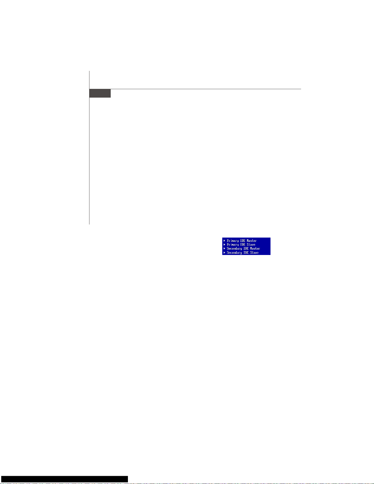
De-24
MS-7345 Mainboard
Aufruf des BIOS Setups
Nach dem Einschalten beginnt der Computer den POST (Power On Self Test Selbstüberprüfung nach Anschalten). Sobald die Meldung unten erscheint, drücken Sie
die Taste <Entf>(<Del>) um das Setup aufzurufen.
Press DEL to enter SETUP
Wenn die Nachricht verschwindet, bevor Sie reagieren und Sie möchten immer noch
ins Setup, starten Sie das System neu, indem Sie es erst AUS- und danach wieder
ANSCHALTEN, oder die “RESET”-Taste am Gehäuse betätigen. Sie können das Sys-
tem außerdem neu starten, indem Sie gleichzeitig die Tasten <Strg>,<Alt> und <Entf>
drücken (bei manchen Tastaturen <Ctrl>,<Alt> und <Del>).
Hilfe finden
Nach dem Start des Setup Menüs erscheint zuerst das Hauptmenü.
Hauptmenü
Das Hauptmenü listet Funktionen auf, die Sie ändern können. Sie können die
Steuertasten (↑↓ ) verwenden, um einen Menüpunkt auszuwählen. Die Online-
Beschreibung des hervorgehobenen Menüpunktes erscheint am unteren Bildschirmrand.
Untermenüs
Wenn Sie an der linken Seite bestimmter Felder ein
Dreieckssymbolf finden (wie rechts dargestellt), bedeuted dies,
dass Sie über das entsprechende Feld ein Untermenü mit
zusätzlichen Optionen aufrufen können. Durch die
Steuertasten (↑↓ )önnen Sie ein Feld hervorheben und durch Drücken der Eingabetaste
<Enter> in das Untermenü gelangen. Dort können Sie mit den Steuertasten Werte
eingeben und navigieren. Durch Drücken von <Esc > kommen Sie zurück ins Hauptmenü.
Allgemeine Hilfe <F1>
Das BIOS Setup verfügt über eine Allgemeine Hilfe (General Help). Sie können diese
aus jedem Menü einfach durch Drücken der Taste <F1> aufrufen. Sie listet die Tasten
und Einstellungen zu dem hervorgehobenen Menüpunkt auf. Um die Hilfe zu verlassen,
drücken Sie <Esc>.
Page 60

De-25
Deutsch
Standard CMOS Features
In diesem Menü können Sie die Basiskonfiguration Ihres Systems anpassen, so z.B.
Uhrzeit, Datum usw.
Advanced BIOS Features
Verwenden Sie diesen Menüpunkt, um weitergehende Einstellungen an Ihrem System
vorzunehmen.
Integrated Peripherals
Verwenden Sie dieses Menü, um die Einstellungen für in das Board integrierte
Peripheriegeräte vorzunehmen.
Power Management Setup
Verwenden Sie dieses Menü, um die Einstellungen für die Stromsparfunktionen
vorzunehmen.
PNP/PCI Configurations
Dieser Eintrag erscheint, wenn Ihr System Plug and Play- Geräte am PCI- Bus unterstützt.
H/W Monitor
Dieser Eintrag zeigt den generellen Systemstatus.
Cell Menu
Hier können Sie ihre Einstellungen zur Kontrolle von Frequenz und Spannung und zur
Übertaktung vornehmen.
Load Fail-Safe Defaults
In diesem Menü können Sie eine stabile, werkseitig gespeicherte Einstellung des BIOS
Speichers laden. Nach Anwählen des Punktes sichern Sie die Änderungen und starten
das System neu.
Load Optimized Defaults
In diesem Menü können Sie die BIOS-Voreinstellungen laden, die der
Mainboardhersteller zur Erzielung der besten Systemleistung vorgibt.
BIOS Setting Password
Verwenden Sie dieses Menü, um das Kennwort für das BIOS einzugeben.
Save & Exit Setup
Abspeichern der BIOS-Änderungen im CMOS und verlassen des BIOS.
Exit Without Saving
Verlassen des BIOS´ ohne Speicherung, vorgenommene Änderungen verfallen.
Das Hauptmenü
Nachdem Sie das AMI® oder AWARD® BIOS CMOS Setup Utility, aufgerufen haben,
erscheint das Hauptmenü. Es weist zehn Setup- Funktionen und zwei Arten das Menü zu
verlassen auf. Verwenden Sie die Pfeiltasten, um im Menü zu navigieren und drücken
Sie die Eingabetaste (<Enter>), um ein Untermenü aufzurufen.
Page 61

De-26
MS-7345 Mainboard
Wenn hereinkommen Sie, gründen das BIOS Dienstprogramm, folgen Sie den Prozessen
unten für allgemeinen Gebrauch.
1. Last optimierte Rückstellungen : Die Gebrauchsteuerschlüssel ( ↑↓ ),, zum der Last
optimierten Rückstellungen hervorzuheben fangen auf und betätigen <Eingabe>,
eine Anzeige wie erscheint unten:
Drücken Sie [okay], um die Standardannahmen für optimale System Leistung zu
laden.
2. Einstellung Datum/ Zeit : Wählen Sie die “Standard-CMOS Eigenschaften” vor und
betätigen Sie <Eingabe> um das Standard-CMOS Eigenschaft -Menü einzutragen.
Justieren Sie das Datum, Zeit fängt auf.
3. Außer u. Ausgang Einstellung : Die Gebrauchsteuerschlussel (↑↓ ), zum der Außer
u. Ausgang Einstellung hervorzuheben fangen auf und betätigen <Eingabe>, eine
Anzeige wie erscheint unten:
Drücken Sie [okay], um die Konfigurationen speichern und das BIOS Einstellung
Dienstprogramm herausnehmen.
Die Konfiguration oben dienen nur generellen Zwecken. Wenn Sie detaillierte
BIOS- Einstellungen benötigen, dann sehen Sie bitte das Handbuch in Englischer
Sprache auf der MSI Website ein.
Wichtig
Page 62

De-27
Deutsch
Software-Informationen
Nehmen Sie den Treiber herausGebrauchs-CD, die im mainboard Paket eingeschlossen
ist, und setzen Sie es in den CD-ROM Treiber. Die Installation wird Automobil-laufen
lassen, klicken Sie einfach den Treiber oder utiltiy und folgen Sie dem pop-up Schirm,
um die Installation durchzuführen. Der TreiberGebrauchs-CD enthält:
Treibermenü - das Treibermenü zeigt die vorhandenen Treiber. Bringen Sie den Treiber
durch Ihren Wunsch und die Vorrichtung zu aktivieren an.
Gebrauchsmenmenü - das Gebrauchsmenü zeigt die SoftwareAnwendungen das die
mainboard Unterstützungen.
WebSite Menü - das Website Menü zeigt die notwendigen Website.
Wichtig
Besichtigen Sie bitte die MSI Website, um die neuesten Treiber und BIOS für
bessere System Leistung zu erhalten.
Page 63

Fr-1
Installation Matériel
Français
P35 Platinum
Guide d’Utilisation
Français
Page 64
Fr-2
La Carte mère MS-7345
Spécificités
Processeur Supporté
- Supporte les processeurs Intel® Core 2 Quad/Duo/Pentium/
Celeron (LGA775)
- Supporte Intel® Yorkfield, Wolfdale
(Pour plus d’informations, veuillez visiter la page
http://global.msi.com.tw/index.php?func=cpuform)
FSB
- 1333/ 1066/ 800 MHz
Chipset
- North Bridge: chipset Intel® P35
- South Bridge: chipset Intel® ICH9R
Mémoire
- DDR2 800/667 SDRAM (8GB Max)
- 4 DDR2 DIMMs (240pin / 1.8V)
(Pour plus d’informations, veuillez visiter la page
http://global.msi.com.tw/index.php?func=testreport)
LAN
- Supports Fast Ethernet PCIE LAN 10/100/1000 par Realtek 8111B
Audio
- Puce intégrée par Realtek® ALC888/ALC888T
- 8-canaux audio flexible avec détéction des connectiques audio
- Compatible avec Azalia 1.0 Spec
- Compatible avec Microsoft Vista Premium spec
- Supporte la carte VoIP (pour ALC888T seulement)
IDE
- 1 port IDE par Marvell 88SE6111
- Supporte le mode Ultra DMA 66/100/133
- Supporte les modes d’opérations PIO, Bus Master
SATA
- 4 ports SATAII avec 2eSATA par ICH9R
- 1 port SATA II par Marvell 88SE6111
- Supporte un stockage et un taux de transfert jusqu’à 300 MB/s
RAID
- Supporte la Technologie Intel Martix Storage (AHCI + RAID 0/1/
5/10) par ICH9R
1394
- Supporte IEEE1394 par VIA VT6308
Page 65

Fr-3
Installation Matériel
Français
FDD
- 1 port de disquette
- Supporte 1 FDD avec 360KB, 720KB, 1.2MB, 1.44MB et 2.88MB
Connecteurs
Panneau arrière
- 1 port souris PS/2
- 1 port clavier PS/2
- 2 ports eSATA (supportent Command Based Port Multipliers)
- 6 ports USB 2.0
- 1 jack LAN (10/100/1000)
- 6 jacks audio flexibles
- 1 port 1394 (optionnel)
- 1 port Sortie S/PDIF Optique(optionnel)
Connecteurs intégrés
- 3 connecteurs USB 2.0
- 1 connecteur 1394 (optionnel)
- 1 connecteur chassis intrusion
- 1 connecteur Sortie SPDIF
- 1 connecteur CD-in
- 2 Hardware Overclocking Cavalier FSB
- 1 connecteur Audio Panneau Avant
- 1 connecteur série
Slots
- 1 slot PCI Express x16
- 2 slots PCI Express x1
- 1 slot PCI Express x4
- 2 slots PCI
- Supporte l’interface 3.3V/ 5V bus PCI
Dimension
- ATX (30.5cm X 24.5cm)
Montage
- 9 trous de montage
Page 66

Fr-4
La Carte mère MS-7345
Guide d’Installation des Composants de la Carte Mère
de la Série P35 Platinum (MS-7345 v1.X)
1
Fr-5
4
Fr-9
3
Fr-7
22
Fr-15
4
Fr-9
6
Fr-9
15
Fr-12
7
Fr-10
21
Fr-15
8 Fr-10
10
Fr-11
4
Fr-9
4
Fr-9
9
Fr-10
11
Fr-11
5
Fr-9
12
Fr-1114Fr-12
17
Fr-13
28
Fr-17
29
Fr-17
19
Fr-13
4
Fr-9
25
Fr-16
26
Fr-16
A
Fr-18
A
Fr-18
H Fr-20
F
Fr-19
P
Fr-20
G
Fr-19
H
Fr-20
Q
Fr-20
K Fr-20
L Fr-20
N Fr-20
Fr-20
I
J
Fr-20
M Fr-20
13 Fr-12
Page 67
Fr-5
Installation Matériel
Français
La carte mère supporte le processeur Intel®. Elle utilise un Socket-775 pour
l’installation.Si vous ne possédez pas de système de refroidissement du CPU, contactez
votre revendeur pour vous en procurer un et installet le avant d’allumer l’ordinateur.
Pour plus d’informations, veuillez consulter: http://global.msi.com.tw/index.php?
func=cpuform
1
Central Processing Unit: CPU
Important
Surchauffe
Une surshauffe peut sérieusement endommager le CPU et le système, assurez-
vous toujours que le système de refroidissement fonctionne correctement pour
protéger le CPU d’une surchauffe. Assurez-vous d’avoir une couche de pâte
thermique (ou bande thermique) entre le CPU et le heatsink pour améliorer la
dissipation de chaleur.
Remplacer le CPU
Avant de remplacer le CPU, éteignez toujours l’alimentation ATX ou débranchez
la prise pour assurer la sécurité du CPU.
Overclocking
Cette carte mère a été créée pour supporter l’overclocking. Veuilez vous assurer
que vos composans peuvent tolérer un tel réglage avant d’iverclocker le syst ème.
Tout essai au-delà des spécificatons des produits n’est pas recommandée.
Nous ne garantissons pas les dommages ou les risques causés par une
opération insatisfaisante ou au-delà des spécifications du produit.
Page 68

Fr-6
La Carte mère MS-7345
Procédure d’installation du CPU pour Socket 775:
1.La douille du CPU porte un chapeau en plastique pour la proté ger
des contacts qui lui causeraient des dommages. Avant d’installé le
CPU, couvrez-le pour protéger la goupille de la douille.
2.Frlevez le chapeau du côté du levier.
3.Les goupilles de la douille se montent.
4.Ouvrez le levier effectif.
5.Soulevez le levier effectif et ouvrez le plat effectif.
6.Après avoir confirmé la direction du CPU pour un jointement correcte,
déposez le CPU dans l’armature de logement de la douille. Soyez
sûr de le prendre sur le bord de la base du CPU. Notez que les clefs
d’alignement sont alors sorties.
7. Inspectez visuellement, si le CPU est bien posé dans la douille.
Dans le cas contraire retirez le CPU avec un mouvement vertical et
réinstallez-le.
8.Couvrez le plat effectif sur le paquet.
9.Appuyez légèrement sur le levier effectif et sur le plat effectif, fixez
ensuite le levier avec le crochet sous l’étiquette de conservation.
10. Alignez les trous de la carte avec le ventilateur. Installez le ventilateur
dans les trous de la carte mère.
11.Appuyez sur les quatre crochets pour attacher le refroidisseur. Puis
effectuez une rotation des systèmes de rétention (référez-vous à la
direction marquée au-dessus) pour fermer les crochets.
12.Retourner la carte mère pour s’assurer que le ventilateur est
correctement installé.
alignment key
Important
1.Vérifiez dans le BIOS les informations de Statut du CPU.
2.Lorsque le CPU n’est pas installé, vous devez remettre la protection sur la
carte mère pour proté ger le socket CPU.
3.Les photos de carte mère dans cette section sont seulement pour la demon-
stration de l’installation du ventilateur du CPU. L’apparence de votre carte
mère varierait dependant le modèle que vous achetez.
Page 69

Fr-7
Installation Matériel
Français
Mémoire
DDR
Spécificité : 184-pin, 2.5v.
Définition du canal unique : Tous les slots DIMM sont Verts.
Définition des canaux double : Slot(s) DIMM sur le canal A est en Vert. Slot(s) DIMM sur
le canal B est en violet .
DDR2
Spécification : 240-pin, 1.8v.
Définition du canal : Tous les slots DIMM sont Verts.
Définition de canaux double: Slot(s) DIMM sur le canal A est en Vert. Slot(s) DIMM sur
le canal B est en Orange .
64x2=128 pin 56x2=112 pin
40x2=80 pin 52x2=104 pin
2
3
Important
- Les modules DDR2 ne sont pas interchangeables avec la DDR et le standard
DDR2 n’est pas compatible en arrière, vous devez toujours installer le
module de la mémoire DDR2 dans la fente de DDR2 DIMM et la DDR dans la
fente de DDR DIMM.
- Fr mode à canal double, assurez-vous bien d’installez les modules de
mémoire du même type et de même densité dans les différentes fentes
du canal DDR DIMM.
- Pour que le système réussi son initialisation-up, insérez les modules de
mémoire dans le DIMM1 d’abord.
Page 70
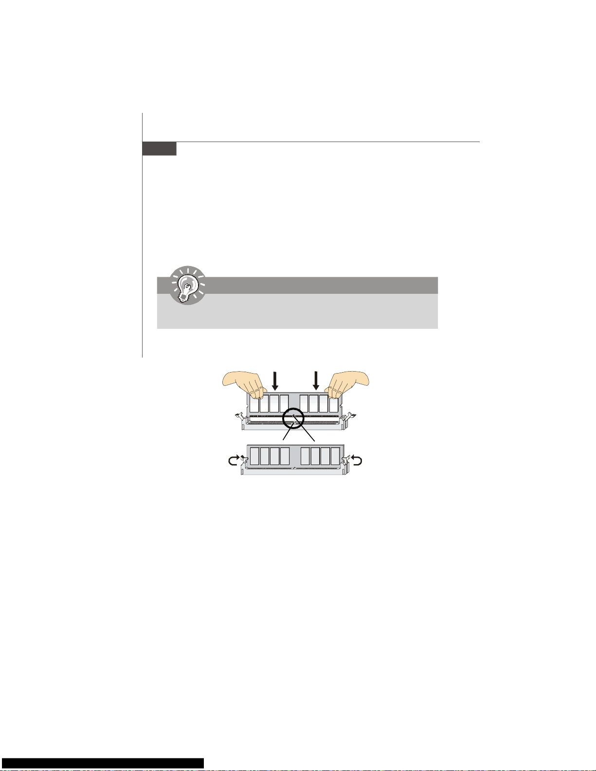
Fr-8
La Carte mère MS-7345
Installation des Modules de Mémoire:
Vous pouvez trouver l’entaille sur les modules de mémoire et le volt sur les fentes de DIMM pour
la DDR ou DDR2. Suivez les procédures ci-dessous pour installer le Module DDR/ DDR2
correctement.
1. Le module de mémoire ne poss ède qu’une encoche en son centre. Le module ne peut être
monté que dans le bon sens.
2. Insérez le module de mémoire DIMM verticalement dans le slot. Poussez-alors le dedans
jusqu'à ce que le doigt d'or sur le module de mémoire soit profondément inséré dans la
douille.
3. Le clip en plastique situé de chaque coté du module va se fermer automatiquement.
Important
Vous ne pouvez pas voir le doigt d’or si le module de la mémoire n’est pas inséré
correctement dans le slot DIMM.
Volt
Frtaille
Page 71

Fr-9
Installation Matériel
Français
Connecteurs, Cavaliers, Slots
Connecteur Pilote de la Disquette
La carte mère est pourvue d’un connecteur de disquette qui supporte les disques de
360K, 720K, 1.2M, 1.44M et 2.88M.
5
Connecteurs Alimentation du Ventilateur:
Les connecteurs au système du ventilateur supportent la puissance du ventilateur avec
+12V. Le CPUFAN1 du CPU supporte la fonctione Smart FAN. Quand vous reliez le fil
aux connecteurs, notez que le fil rouge est positif et doit être relié au +12V, le fil noir
est rectifié et mis à terre. Si la carte mère a un chipset intégré sur le moniteur de
matériel du système, vous devez utiliser un ventilateur particulier avec une sonde de
vitesse pour bien contôler le ventilateur.
SYS FAN/ NB FAN/
POWER FAN
SENSOR or NC
+12V
GND
4
Connecteru IDE
Cette carte mère fournit un connecteur IDE qui supporte les lecteurs de disque dur, les
lecteursCD-ROM et les autres dispositifs IDE.
6
CPU FAN
SENSOR
+12V
GND
Control
Important
1.Veuillez référer-vous au ventilateur du CPU recommendé dans le site web
officiel ou contactez au revendeur pour le ventilateur correct du CPU.
2.CPUFAN supporte le contrōle du ventilateur. Vous pouvez installer l’utilitaire
Dual Core Center qui peut contrōler la vitesse du ventilateur du CPU selon la
température actuelle du CPU.
3. Ventilateur/radiateur avec 3 ou 4 pins sont disponibles pour CPUFAN.
Important
Si vous installez 2 disques durs sur une même nappe, vous devez configurer le
second disque en mode Slave (esclave) en bougeant les cavaliers. Pour cela, il
faut vous reporter à la documentation du disque dur concernant le changement de
cavalier (jumpers).
Page 72

Fr-10
La Carte mère MS-7345
Connecteurs panneau en façade
La carte mère possède deux connecteurs pour la connexion électrique du panneau
avant (LED, switch). JFP1 est compatible avec l’Intel® Front Panel I/O Connectivity
Design Guide.
8
9
Connecteur Série ATA
Le connecteur SATA supporte le port Serial ATA de hautes performances. Chaque
connecteur de SATA peut se connecter à un disque dur.
7
Important
Veuillez ne pas tordre le câble Série ATA à90 degrés, cela entraî nera la perte
de données lors des phases de transfert.
Connecteur IEEE 1394 (Vert)
La carte comporte un connecteur 1394 qui vous permet la connexion de bracket
externes IEEE1394.
IEEE1394 Bracket
(Optionnel)
JFP2
7
8
Power LED
Speaker
12
JFP1
1
2
910
HDD
LED
Reset
Switch
Power
LED
Power
Switch
1
2
9
10
TPA-
Ground
TPB-
Cable power
Ground
TPA+
Ground
TPB+
Cable power
Key (no pin)
Page 73

Fr-11
Installation Matériel
Français
10
Connecteurs panneau en façade (Azalia Spec)
Le connecteur vous permet de connecter l’audio en façade qui est compatible avec
l’Intel® Front Panel I/O Connectivity Design Guide.
11
12
1
2
910
MIC _L
MIC _R
LINE out_R
Front_JD
LINE out_L
Ground
Presence#
MIC_JD
NC(No pin)
LINE out_JD
Connecteur USB en façade (Jaune)
Ce connecteur est compatible avec IntelR I/O Connectivity Design Guide, il est idéal
pour la connexion de matériels possédant une interface USB tel que: disque dur USB,
camé ra digitale, imprimante, lecteur MP3 et bien d’autres périphériques.
Important
Notez que les pins de VCC et de GND doivent être reliés correctement pour éviter
des dommages possibles.
USB 2.0 Bracket
(Optionnel)
Le connecteur de sortie S/PDIF (optionnel, pour les cartes graphiques HDMI
seulement)
Ce connecteur est utilisée pour connecter l’interface S/PDIF (Format d’interconnexion
numérique Sony et Philips) afin de transmettre le son audio numérique vers les cartes
graphiques HDMI.
USBOC
10
1
2
VCC
USB0-
USB0+
GND
Key (no pin)
VCC
USB1-
USB1+
GND
9
SPDIFO
GND
1
2
Page 74

Fr-12
La Carte mère MS-7345
Connecteur CD-Frtrée
Ces connecteurs permettent l’audio input externe..
Connecteur Chassis Intrusion
Ce connecteur est connecté au câble de chassis intrusion switch. Si le chassis est ouvert,
le switch en informera le système, qui enregistrera ce statut et affichera un écran
d’alerte. Pour effacer ce message d’alerte, vous devez entrer dans le BIOS et désactiver
l’ alerte.
GND R
L
15
13
14
1
2
CINTRU
GND
Hardware Overclock Cavaliers FSB: JB1, JB2 (optionnel)
Vous pouvez overclocké le FSB pour augmenter la fréquence du processeur en
ajuster les cavaliers JB1 et JB2. Suivez les instructions en dessous pour ajuster le
FSB.
Important
Assurez-vous que vous avez l’ordinateur est éteint avant d’ajuster les cavaliers.
1
266 MHz
1
3
200 MHz
1
3
JB1 JB2
333 MHz
1
3
Page 75
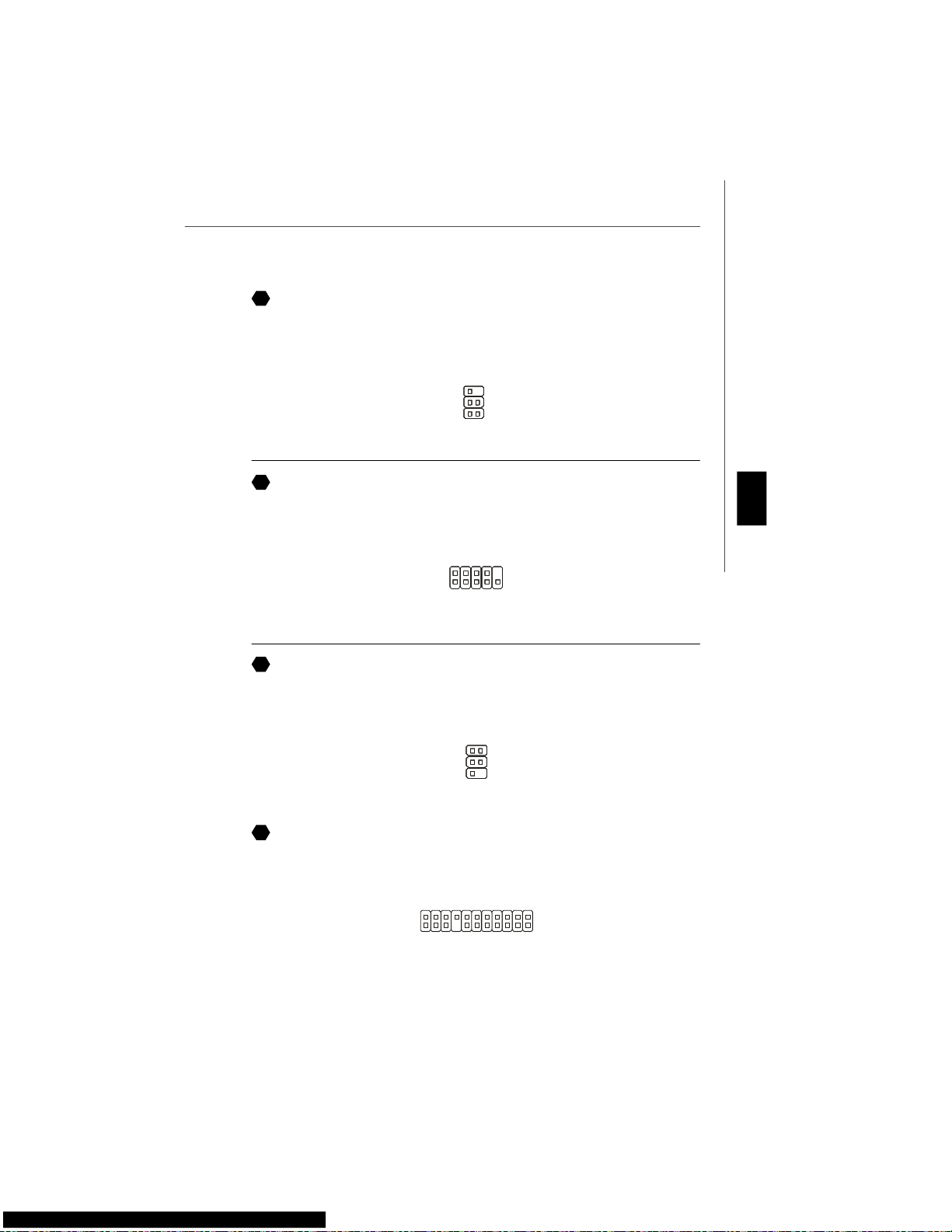
Fr-13
Installation Matériel
Français
Connecteur Module Infrarouge
Ce connecteur permet la mise en place d’un module Infrarouge. Vous devez configurer
cette fonction dans le BIOS afin de pouvoir l’utiliser. JIR1 est compatible avec l’Intel
®
Front Panel I/O Connectivity Design Guide.
Connecteur Port Série
Le port série est un port de communication 16550A à grande vitesse qui envoie/ reçoit
16 bytes FIFOs. Vous pouvez directement attacher un dispositif série au connecteur.
Connecteur TV-Sortie
Le connecteur SortieTV vous permet d’attacher un bracket Sortie-TV. Le bracket TV
vous offre plusieurs types de connecteurs de SortieTV. Choisissez le connecteur approprié
pour vous relier à une télévision.
6
5
2
1
NC
VCC5
IRTX
NC
Ground
IRRX
16
17
18
3
1 4
Ground
Yout
Cout
COMP or CVBS
Ground (5)
1
5
6
DCD
SIN
SOUT
DTR
Ground
DSR
RTS
CTS
RI (9)
Connecteur Carte VoIP
Ce connecteur relie à la carte VoIP. Veuillez vous référer aux instruxions de la carte
VoIP.
19
Page 76

Fr-14
La Carte mère MS-7345
1
9
2
10
DBG1
DBG2
DBG3
DBG4
Key
DBR1
DBR2
DBR3
DBR4
NC
BIOS Connecté
Ceci montre des informations sur le
logo, marque et processeur etc...
Essai de la mémoire basse et
prolongée.
Mémoire basse d’ essai de 240K à
640K et mémoire prolongée plus
de1MB en utilisant divers modèls.
Ressources assignées à tout
l’ ISA.
Contrôleur d’ Initialisation du
conducteur dur.
Ceci initialise la commande et le
contrôleur d’ IDE.
Contrôleur Initialisation Floppy
Drive.
Ceci initialise le Floppy Drive et le
contrôleur .
Tentative d’initialisation.
Place la pile Basse et l’initialise
via19h INTERNE.
Initialisation du Logiciel
d’exploitation
Allumez le système.
Le D-LED s’allumera si le
processeur est endommagé ou
installé de façon incorrecte.
Contrôleur d’ Initialisation du
Clavier.
Essai VGA BIOS
Ceci commence à écrire le
message sign-on de VGA à
l’écran.
Processeur d’ Initialisation.
Ceci nous informe sur le
processeur (comme le nom de la
marque, bus de système, etc...)
TEssai RTC (Horloge en temps
réel)
Description
Rouge
Vert
LED Signal
1 2
3 4
1 2
3 4
1 2
3 4
1 2
3 4
1 2
3 4
1 2
3 4
1 2
3 4
1 2
3 4
Description
LED Signal
1 2
3 4
1 2
3 4
1 2
3 4
1 2
3 4
1 2
3 4
1 2
3 4
1 2
3 4
1 2
3 4
Chipset en phase d’ initialisation.
Essai de Dé tection De Mé moire.
Essai de la capacité de la mémoire
intégrée. Le D-LED s’allumera si le
module de mé moire est
endommagé ou non installé
correctement.
Décompression de l’ image du BIOS
à la RAM pour initialiser
rapidement.
IInterface Visuelle d’Initialisation.
Ceci détecte l’horloge du CPU, la
vérification du type de vidéo intégrée.
Puis, détectez et initialisez
l’adapteur visuel.
Connecteur D-Bracket™ 2
Le connecteur est utilisé pour connecter le D-Bracket™ 2. Le D-Bracket est pourvu de 4
LED et ports USB et permet d’identifier les problèmes et ce à l’aide de 16 combinaisons
de signaux LED.
20
D-Bracket™ 2
(Optionnel)
Connecter sur
JDB1
Connecter sur
connecteur USB
Page 77

Fr-15
Installation Matériel
Français
Connecteur Chassis Intrusion Switch
Ce connecteur est connecté au câble de chassis intrusion switch. Si le chassis est ouvert,
le switch en informera le système, qui enregistrera ce statut et affichera un écran
d’alerte. Pour effacer ce message d’alerte, vous devez entrer dans le BIOS et désactiver
l’ alerte.
Vous pouvez utiliser l’alimentation d’énergie 20-pin ATX comme vous voulez. Si vous
ne voulez pas l’utiliser, veuillez brancher votre alimentation d’énergie au pin1 & pin13.
Bouton Effacer CMOS
Le CMOS RAM intégré reçoit une alimentation d’une batterie externe qui permet de
garder les données de configuration du système. Avec le CMOS RAM, le système peut
automatiquement démarrer avec les paramètres personnalisés du BIOS à chaque fois
que le PC est allumé. Si vous voulez effacer la configuration du système, utilisez ce
bouton pour effacer les données. Pressez sur le bouton pour effacer les données.
Attachement d’Alimentation d’Énergie:
Avant d’insérer le connecteur d’alimentation d’énergie, assurez-vous toujours que tous
les composants sont installés correctement afin de ne pas causer de dommage. Tous
les connecteurs de puissance sur la carte mère doivent se relier à l’alimentation d’énergie
d’ATX et doivent travailler ensemble pour une opération stable.
22
1
1224
13
+3.3V
+3.3V
GND
+5V
GND
+5V
GND
PWR OK
5VSB
+12V
+12V
+3.3V
GND
+5V
+5V
+5V
NC
GND
GND
GND
PS-ON#
GND
-12V
+3.3V
21
Important
Assurez-vous que vous d’éteindre le système avant d’effacer les données du
CMOS.
Page 78
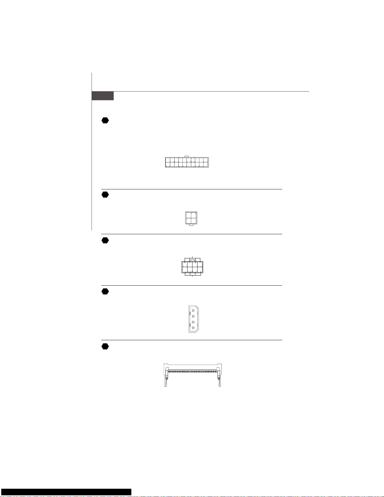
Fr-16
La Carte mère MS-7345
Connecteur NV SLI
Ce connecteur est utilisé pour configurer la carte du commutateur SLI au mode SLI ou
non-SLI.
Connecteur Alimentation ATX 12V (2x2-Pin)
Ces connecteurs de puissance 12V sont utilisés pour fournir de la puissance au CPU.
Connecteur Alimentation ATX 12V(2x4-Pin)
Le connecteur d’alimentation 12V est utilisé pour alimenter le CPU.
Connecteur Alimentation ATX 12V (1x4-Pin)
Ce connecteur de puissance 12V est utilisé pour fournir de l’énergie à la carte mère.
1
34
2
GND
12V
GND
12V
4
2
1
3
5V
GND
GND
12V
Connecteur Alimentation ATX 20-Pin
Ce connecteur vous permet de relier à l’alimentation offerte ATX 20-pin .Pour relier
cette alimentation, assurez-vous que la prise d’alimentation d’énergie est insérée dans
l’orifice approprié et que les pins sont alignés. Abaissez alors l’alimentation d’énergie.
23
24
25
26
27
1
10
20
11
3.3V
3.3V
GND
5V
GND5VGND
PWR OK
5VSB
12V 5V
5V
-5V
GND
GND
GND
PS-ON
GND
-12V
3.3V
8
4
1
5
GND
+12V
Page 79

Fr-17
Installation Matériel
Français
Slot PCI Express (x16/ x4/ x1)
Le slot PCI Express supporte la carte d'extension de l'interface PCI Express.
Le PCI Express x 16 supporte un taux de transfert jusqu'a 4.0 GB/s.
Le PCI Express x 8 supporte un taux de transfert jusqu'a 2.0 GB/s.
Le PCI Express x 4 supporte un taux de transfert jusqu'a 1.0 GB/s.
Le PCI Express x 1 supporte un taux de transfert jusqu'a 250 MB/s.
Slot PCI Express x 16
Slot PCI Express x 4
Slot PCI Express x 1
Slot de PCI (Interconnexion Composante Périphérique)
Les slots PCI vous permettent d’insérer des cartes d’extension selon vos besoins. Lorsque
vous ajoutez ou enlever une carte d’extension, assurez-vous que le PC n’est pas relié au
secteur. Lisez la documentation pour que la carte d’extension exécute ses tāches.
Slot d’AGP (Port Accelered et Graphique)
Le slot AGP vous permet d’insérer la carte graphique AGP, interface spécifique conçue
pour les demandes de 3D graphiques. Elle comporte un 66MHz, canal de 32 bits pour
que le contrôleur graphique accède directement à la note principale.
28
29
30
Important
Lorsque vous ajoutez ou enlevez une carte d’extension, assurez-vous que le PC
n’est pas relié au secteur. Lisez la documentation pour que la carte d’extension
exécute ses tâches, tels que cavaliers, commutateurs ou configuration du BIOS.
Page 80

Fr-18
La Carte mère MS-7345
Panneau Arrière
Connecteur port Souris/ Clavier
Le connecteur PS/2® souris/clavier DIN est conçu pour brancher un PS/2® souris/
clavier.
Connecteur Port Parallèle :
Un port parallèle est un port d’imprimante standard qui supporte le port parallèle
amé lioré (EPP, Frhanced Parallel Port) et le mode d’ECP(Extended Capabilities Parallel Port)
Connecteur Port Série
Le port série est un port de communication 16550A à grande vitesse qui envoie/ reçoit
16 bytes FIFOs. Vous pouvez directement attacher une souris série ou d’autres dispositifs
séries au connecteur.
Connecteur VGA
Le connecteur DB15-pin femelle est conçu pour être relié à un moniteur VGA.
(Connecteur 9-Pin Masculin)
1 5
6 9
13 1
1425
(Connecteur 25-pin féminin)
Connecteur PS/2 Souris (Vert / 6-pin féminin)
Connecteur PS/2 Clavier(Violet/ 6-pin féminin)
(Connecteur 15-Pin Féminin DIN )
15
1115
A
B
C
D
Page 81
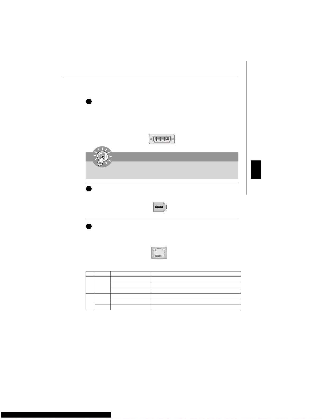
Fr-19
Installation Matériel
Français
Port 1394
Le port 1394 sur le panneau arrière fournit le raccordement pour les dispositifs 1394.
Connecteur DVI
Le connecteur DVI (interface visuelle numérique) vous permet de relier un moniteur
LCD . Il fournit une interconnexion numérique à grande vitesse entre l’ordinateur et son
dispositif d’affichage. Pour relier un moniteur LCD, branchez simplement votre câble
de moniteur au connecteur DVI, et assurez-vous que l’autre extrémité du câble est
correctement reliée à votre moniteur. (référez-vous à votre manuel de moniteur pour
plus d’informations.)
1
24
17
8
Important
Veuillez noter que le connecteur de DVI ne supporte pas de connext du DSecondaire(D-Sub) au convertisseur de DVI.
E
F
LAN
Le standard RJ-45 jack est utile pour le raccordement au Réseau de Région Local
(LAN). Vous pouvez relier un câble de réseau à celui-ci.
G
LED Couleur LED Statut Condition
Éteint Le lien LAN n’est pas é tabli.
GaucheOrange Allumé(steady state) Le lien LAN est établi.
Allumé(brighter & pulsing) L’ordinateur communique avec un autre ordinateur sur le ré seau.
Vert Éteint 10 Mbit/sec rate de données est sélectionné.
Droite Allumé 100 Mbit/sec rate de données est sélectionné.
Orange Allumé 1000 Mbit/sec rate de données est sélectionné.
Page 82

Fr-20
La Carte mère MS-7345
Connecteurs USB
La racine Serial Universel Autobus d’OHCI (Interface Ouverte de Contrôle du Centre
Serveur) sert à attacher des dispositifs d’USB tels que le clavier, souris ou d’autres
dispositifs USB-compatibles. Vous pouvez directement brancher le dispositif USB au
port.
Connecteurs Port Audio
Ces connecteurs audio sont utilisés pour les dispositifs audios. Vous pouvez différencier
la couleur des jacks audio pour les sons audio différents .
Ligne Sortie (Vert) - Ligne Sortie, un connecteur pour les haut-parleurs ou les écouteurs.
Ligne-Frtrée (Bleu) - Ligne Frtrée/ Côté-entourez sortie en mode de 7.1 canaux est utilisé pour le player de CD
externe, tapeplayer ou d’ autres dispositifs audio.
MIC (Rosé) - Mic-entrée est un connecteur pour les microphones.
CS-Sortie (Orange) - Centre/subwooffer sortie en mode de 5.1/ 7.1 canaux.
RS-Sortie (Noir) -Côté-arrière sortie en mode de 4/5.1/ 7.1 canaux.
SS- Sortie (Gris) - Côté-entourez sortie en mode de 7.1 canal
Connecteur Sortie S/PDIF Coaxial
Ce connecteur est utilisé pour relier l’interface de SPDIF(Format d’interconnexion
numérique de Philips /Sony ) pour la transmission audio numérique.
Connecteu S/PDIF-Sortie Optique
Ce connecteur est utilisé pour relier l’interface de SPDIF(Format d’interconnexion
numérique de Philips /Sony ) pour la transmission audio numérique.
J
L
H
I
K
M
N
O
P
Port Externe SATA
Le port eSATA (External Sérial ATA) est utilisé pour relier le dispositif externe SATA.
Vous pouvez aussi utiliser le câble externe optique SATA pour relier le dispositif SATA
et le port eSATA.
Q
Page 83

Fr-21
Installation Matériel
Français
Indicateur d’état LED
Nom état
LED1 Allumer quand le système est démarré.
LED3 Allumer quand le système est en mode veille.
LED11 Allumer quand le slot PCI_E3 est en fonction.
LED12 Allumer quand le slot PCI_E4 est en fonctionne.
LED13 Allumer quand le slot PCI1 est en fonctionne.
LED14 Allumer quand le slot PCI2 est en fonctionne.
LED15 Allumer quand le slot PCI_E1 est en fonctionne.
LED16 Allumer quand le slot PCI_E2 est en fonctionne.
LED14
LED13
LED12
LED16
LED15
LED11
LED3
LED1
LED20
LED10
LED19
LED9
LED18
LED8
LED17
LED7
Page 84

Fr-22
La Carte mère MS-7345
LED 7, 8, 9 ,10, 17, 18, 19, 20
Ces 4 LEDs vous permettent d’identifier les problèmes du système ą travers les 16
différentes combinations des signaux LED.
BIOS Sign On
Ceci redémarra l’ affichage des informations ą propos du logo, nom de la
marque du processeur, etc...
Test de la mémoire de base et de
l’extension de mé moire.
Test de la mémoire de base de 240K
ą 640K et de la mé moire d’ extension
au dessus de 1MB utilisation de divers
modčle
Assigne les Ressources ą tous
ISA.
Initialisation du contrōleur du disque
dur.
Ceci initialisera le contrōleur IDE du
disque dur.
Initialisation du contrōleur du lecteur
de disquette.
Ceci initialisera le contrōleur du
lecteur de disquette.
Tentative Boot
Ceci diminuera la consommation
de la pile et démarra via INT 19h.
Operation de Démarrage du
Système
Système dé marré
Le D-LED va s’arrźter si le
processeur est endommagé ou n ’ est
pas bien installé.
Initialisation du contrôleur clavier.
Test le BIOS VGA
Cela commencera ą écrire un mes-
sage signal VGA ą l’écran.
Initialisation du Processeur
Ceci affichera les informations
concernant le processeur(nom du
fabricant, Bus systeme, etc...)
Test RTC (Real Time Clock)
Description
Rouge
Vert
LED Signal
Description
LED Signal
Initialisation Early Chipset
Test Dé tection de la Mémoire.
Test sur la carte de la taille de la
mémoire. La D-LED va s’arrźter si
le module de mémoire est
endommagé ou n’est pas bien
installé.
Décompression de l’ image BIOS ą la
RAM pour pouvoir dé marrer plus vite.
Initialisation de l’ interface Vidéo
Ceci dé marra la dé tection CPU clock,
vé rification de type de vidéo
embarquée. Alors, l’ adaptateur vidéo
est détecté et initialisé.
LED20
LED10
LED19
LED9
LED18
LED8
LED17
LED7
Groupe1
Groupe2
Groupe3
Groupe4
Groupe4
Groupe3
Groupe2
Groupe1
Groupe4
Groupe3
Groupe2
Groupe1
Groupe4
Groupe3
Groupe2
Groupe1
Groupe4
Groupe3
Groupe2
Groupe1
Groupe4
Groupe3
Groupe2
Groupe1
Groupe4
Groupe3
Groupe2
Groupe1
Groupe4
Groupe3
Groupe2
Groupe1
Groupe4
Groupe3
Groupe2
Groupe1
Groupe4
Groupe3
Groupe2
Groupe1
Groupe4
Groupe3
Groupe2
Groupe1
Groupe4
Groupe3
Groupe2
Groupe1
Groupe4
Groupe3
Groupe2
Groupe1
Groupe4
Groupe3
Groupe2
Groupe1
Groupe4
Groupe3
Groupe2
Groupe1
Groupe4
Groupe3
Groupe2
Groupe1
Groupe4
Groupe3
Groupe2
Groupe1
Page 85

Fr-23
Installation Matériel
Français
Configuration du BIOS
Ce chapitre vous informe sur le programme d’installation du BIOS et vous permet de
configurer le système pour un usage optimum. Vous pouvez installer le programme
lorsque:
* Un message d’erreur apparaît sur l’écran pendant que le système initialise et vous
demande de mettre en marche l’INSTALLATION de BIOS.
* Vous voulez changer les arrangements par défaut pour des dispositifs adaptés aux
besoins du client.
Important
1. Les articles de chaque catégorie de BIOS décris dans ce chapitre sont mis à
jour en continu pour un meilleur système. Par conséquent, la description peut
légèrement différer du dernier BIOS et elle doit seulement être considérée
comme une r éférence.
2. Sur l’initialisation, la 1ère ligne est la version d u BIOS qui apparaît après
le compte de la mémoire. Il est habituellement au f ormat :
A7345IMS V1.0 011507 soit :
Le 1er chiffre se rapporte au fabricant de BIOS en tant qu’A = AMI, W =
RÉCOMPENSE et P = PHOENIX.
2ème - le 5ème chiffre se rapporte au numéro du type.
Le 6ème se rapporte au vendeur de chipset en tant qu’A = ATi, I = Intel, V = VIA
(PAR L’INTERMÉDIAIRE DE), N = Nvidia, U = ULi.
7ème - le 8ème chiffre se rapporte au client comme MME = tous les clients
standards.
V1.0 se rapporte à la version de BIOS.
011507 se rapporte à la date où ce BIOS a ét é libéré.
Page 86
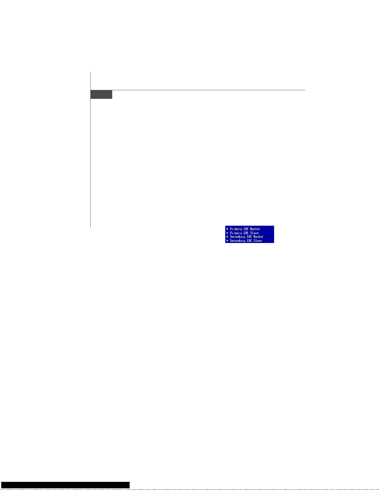
Fr-24
La Carte mère MS-7345
Frtrer dans le Setup
Allumez votre ordinateur, le système lance le processus de POST (Power On Self Test).
Quand le message ci-dessous apparaît à l’écran, appuyez sur le bouton <DEL> pour
entrer dans le setup.
Pressez DEL pour entrer dans le SETUP
Si le message disparaît avant que vous ne puissiez entrer dans le setup, redémarrez
votre ordinateur en appuyant sur le bouton RESET. Vous pouvez aussi utiliser
simultanément la combinaison de touches : <Ctrl>, <Alt> et <Delete>.
Aide
Une fois dans le Setup, le 1er écran est celui du menu principal.
Menu Principal
Le menu principal affiche les différentes catécories du BIOS, utilisez les fleches ( ↑↓ )
pour sélectionner l’article. La description en ligne de la fonction accentuée d’installation
est montrée en fond d’écran.
Sub-Menu
Si vous voyez que le symbole correcte apparaît à la gauche
de certains champs, cela signifie qu’un sous-menu peut être
lancé de ce champ. Un sous-menu contient des options
additionnelles pour un paramètre de champ. Avec les touches
de déplacement ( ↑↓ ) pour présenter le champ ou presser<
entrée > pour appeler le sous-menu. Alors vous pouvez déplacer de champ en champ
dans un sous-menu. Si vous voulez retourner au menu principal, pressez juste < ESC >.
Aide Générale <F1>
Le programme d’installation de BIOS contient un écran général d’aide. Vous pouvez
appeler cet écran de tout menu par la pression de < F1 >. L’écran d’aide vous donne
des choix possibles . Pressez< ESC > pour sortir l’écran d’aide.
Page 87

Fr-25
Installation Matériel
Français
Standard CMOS Features
Cette fonction permet le paramétrage des éléments standards du BIOS , comme les
dates, les données etc.
Advanced BIOS Features
Cette fonction permet de paramètrer des éléments avancés AMI® du BIOS.
Integrated Peripherals
Utilisez ce menu pour changer les choix relatifs aux périphériques intégrés.
Power Management Setup
Utilisez ce menu pour appliquer vos choix en ce qui concerne le power management.
PNP/PCI Configurations
Apparaît si votre système supporte PNP/PCI.
H/W Monitor
Voir les statuts des CPU, ventilateurs et système d’alarmes.
Cell Menu
Utilisez ce menu pour spécifier vos paramètres pour la fréquence et le voltage du CPU.
Load Fail-Safe Defaults
Utilisez ce menu pour télécharger les valeurs par défaut réglées par le vendeur du BIOS
pour obtenir une performance stable du systčme.
Load Optimized Defaults
Charge les paramètres optimum du BIOS sans affecter la stabilité du système.
BIOS Setting Password
Utilisez ce menu pour entrer un mot de passe du BIOS.
Save & Exit Setup
Les modifications sont enregistrées dans le CMOS avant la sortie du setup.
Exit Without Saving
Les modifications sont abandonnées avant la sortie du setup.
Menu Principal
Une fois entré dans le AMI® ou AWARD® BIOS CMOS Setup Utility, le menu apparaît à
l’écran. Le Menu permet de sélectionner dix fonctions et deux choix de sortie de
l’utilitaire. Utilisez les flèches pour vous diriger et utilisez la touche ENTREE pour
sélectionner un élément ou entrer dans le sous-menu.
Page 88

Fr-26
La Carte mère MS-7345
Une fois que vous êtes entré dans l’installation de BIOS, suivez les processus ci-dessous.
1.Load Optimized Defaults : Utilisez les touches de contrôle( ↑↓ ) pour accentuer le
champ de Load Optimized Defaults(Charge Optimisée par Défaut) et la pression <
Frtrer >, pour obtenir le message suivant:
Pressez [ Correct ] pour effectuer les arrangements de défaut et pour l’exécution
optimale de système.
2.Installation Date/ Temps : Choisissez les dispositifs standards de CMOS et la pression
< Frtrée > dans le dispositif-menu standard de CMOS. Ajustez la date et les Champs
de temps:
3. Installation économie/sortie : Les touches de contrôle ( ↑↓ )servent à accentuer le
champ d’installation d’économie/sortie et de la pression <Frtrée>, le message suivant
s’affiche:
Pressez [ Correct ] pour sauver les configurations et sortir de l’installation du BIOS.
Important
Les configurations ci-dessus ne sont que pour l’usage général. Si vous avez
besoin d’arrangements détaillés du BIOS, veuillez consulter le manuel (la
version franç aise) sur le Web de site de MSI.
Page 89

Fr-27
Installation Matériel
Français
Information de Logiciel
Sortez le pilote/Service du CD, qui est inclus dans le paquet de la carte mère et
placez-le dans le CD-ROM.L’installation va automatiquement se déclencher, cliquez
sur le pilote ou sur l’usage et suivez le pop-up de l’écran pour accomplir
l’installation. Le pilote/Service CD contient :
Un menu de pilote -Il montre les pilotes disponibles. Installez le pilote si vous le
souhaitez pour activer le dispositif.
Menu de services – Il montre les applications logicielles supportées par la carte mère.
Le menu du site Web – Il vous indique les sites webs utiles.
Important
Veuillez consulter le site Web de MSI pour obtenir les derniers pilotes et BIOS
pour améliorer l’ exécution du système de votre ordinateur.
Page 90

Ru-1
Руководство по установке
Русский
P35 Platinum
Руговодство
пользователя
Русский
Page 91
Ru-2
MS-7345 Mainboard
Характеристики
Процессоры
- Intel® Core 2 Quad/Core 2 Duo/Pentium/Celeron процессоры с
разъемом LGA775
- Поддерживают Intel® Yorkfield, Wolfdale
(Для получения новых сведений о процессорах посетите сайт
http://global.msi.com.tw/index.php?func=cpuform)
FSB
- 1333/ 1066/ 800 МГц
Чипсет
- Северный мост: Intel® P35
- Южный мост: Intel® ICH9R
Память
- DDR2 800/667 SDRAM (8ГБ Макс)
- 4 слота DDR2 DIMM (240-конт / 1.8В)
(For more information on compatible components, please visit http:/
/global.msi.com.tw/index.php?func=testreport)
LAN
- Поддержка PCIE LAN 10/100/1000 Fast Ethernet (Realtek
8111B)
Аудио
- Контроллер Realtek® ALC888/ALC888T
- 8-канальный аудио с гибким переназначением разъемов
ввода/вывода
- Совместим со спецификацией Azalia 1.0
- Совместим со спецификацией Microsoft Vista Premium
- Поддержка карты VoIP (только для ALC888T)
IDE
- 1 IDE порт на контроллере Marvell 88SE6111
- Поддержка режима Ultra DMA 66/100/133
- Поддержка режима работы PIO, Bus Master
SATA
- 4 SATAII порта, включая 2 eSATA порта на чипсете ICH9R
- 1 SATA II порт на контроллере Marvell 88SE6111
- Поддержка скорости передачи данных до 300 Mб/с
RAID
- Поддерживает технологию Intel Martix Storage (AHCI + RAID
0/1/5/10) на чипсете ICH9R
Page 92

Ru-3
Руководство по установке
Русский
1394
- Поддержка 1394 на чипсете VIA VT6308
Флоппи
- 1 флоппи порт
- Поддержка 1-го FDD с 360КБ, 720КБ, 1.2МБ, 1.44МБ и 2.88МБ
Разъемы
Задняя панель
- 1 PS/2 порт для подключения мыши
- 1 PS/2 порт для подключения клавиатуры
- 2 eSATA порта (поддержка Command Based Port Multipliers)
- 6 USB 2.0 портов
- 1 LAN разъем (10/100/1000)
- 6 портов аудио
- 1 1394 порт (опционально)
- 1 оптический порт S/PDIF-Out (опционально)
Разъемы на системной плате
- 3 USB 2.0 разъема
- 1 1394 разъем (опционально)
- 1 разъем датчика открывания корпуса
- 1 SPDIF-out разъем
- 1 CD-in разъем
- 2 Переключатели режимов FSB
- 1 звуковой разъем передней панели
- 1 последовательный разъем
Слоты
- 1 PCI Express x16 слот
- 2 PCI Express x1 слота
- 1 PCI Express x4 слот
- 2 PCI слота
- Поддержка интерфейса PCI bus 3.3В/ 5В
Форм фактор
- ATX (30.5см X 24.5см)
Крепление
- 9 отверстий для крепления
Page 93

Ru-4
MS-7345 Mainboard
Краткое описание разъемов и переключателей
системной платы серии P35 Platinum
(MS-7345 v1.X)
1
Ru-5
4
Ru-9
3
Ru-7
22
Ru-15
4
Ru-9
6 Ru-9
15
Ru-12
7
Ru-10
21
Ru-15
8 Ru-10
10
Ru-11
4
Ru-9
4
Ru-9
9
Ru-10
11
Ru-11
5
Ru-9
12
Ru-11
14
Ru-12
17
Ru-13
28
Ru-17
29
Ru-17
19
Ru-13
4
Ru-9
25
Ru-16
26
Ru-16
A
Ru-18
A
Ru-18
H Ru-20
F
Ru-19
P
Ru-20
G
Ru-19
H
Ru-20
Q
Ru-20
K Ru-20
L Ru-20
N Ru-20
Ru-20
I
J
Ru-20
M Ru-20
13 Ru-12
Page 94
Ru-5
Руководство по установке
Русский
Центральный процессор (CPU)
Эта системная плата поддерживает процессор от Intel®. Для облегчения
установки процессора на ней установлен разъем под названием Socket 775. Если
у вас нет процессорного кулера, пожалуйста, свяжитесь с дилером с целью
приобретения и его установки до того, как включите компьютер.
Самую последнюю информацию о поддерживаемых процессорах можно
получить на сайте
http://global.msi.com.tw/index.php?func=cpuform
1
Внимание
Перегрев
Перегрев может серьезно повредить центральный процессор и систему.
Чтобы уберечь процессор от перегрева, убедитесь в том, что
процессорный кулер работает нормально. Чтобы увеличить
теплорассеивание, убедитесь в том, что нанестите слой
теплопровадящей пасты (или теплопровадящей ленты) между
процессором и оребрениями.
Замена CPU
При замене CPU, во избежание его повреждения, обязательно
отключите источник питания или выньте вилку блока питания из
розетки.
Разгон
Эта системная плата поддерживает «разгон». Однако, убедитесь, что
компоненты системы способны работать в таких нестандартных
режимах. Не рекомендуется использовать продукт в режимах не
соответствующих указанным в спецификациях.
Page 95
Ru-6
MS-7345 Mainboard
Установка процессора и вентилятора для Socket 775
1. Разъем процессора закрыт пластиковой крышкой, которая
защищает контакты разъема от повреждений и загрязнений. Если
процессор не установлен в разъем, необходимо всегда закрывать
его пластиковой крышкой для защиты от пыли и повреждений.
2. Снимите крышку, подняв ее с одной стороны.
3. Откроются контакты разъема.
4. Поднимите рычаг и откройте разъем для установки процессора.
5. Убедившись в правильной ориентации процессора, положите
процессор в разъем. Обратите внимание, что выемки на
процессоре должны соответствовать выступам на
процессорном разъеме.
6. Проверьте правильность установки процессора в разъем
визуально. Если процессор установлен неправильно, то выньте
процессор и переустановите.
7. Опустите мателлическую крышку механизма крепления.
8. Аккуратно опустите рычаг на крышку механизма крепления и
зафиксируйте его. Для фиксации рычага в механизме крепления
предусмотрен маленький крючок.
9. Совместите отверстия системной платы с защелками крепления
вентилятора. Прижмите радиатор с вентилятором к процессору
и проследите, чтобы четыре защелки вошли в отверстия
системной платы.
10.Нажмите на четыре защелки и закрепите вентилятор. Затем
поверните фиксаторы защелок (направление поворота указано
на вентиляторе) и закрепите их.
11.Переверните системную плату и убедитесь, что защелки надежно
удерживают вентилятор.
alignment key
Внимание
1. Смотрите состояние процессора в разделе BIOS.
2. Если процессор не установлен, всегда закрывайте разъем пластиковой
крышкой для предотеращения поломок и попадания в него грязи и пыли.
3. Фото системной платы, показываемые в этой части ,- только демострация
установки вентилятора. Выступление системной платы зависит от
модели, купленной вами.
Page 96

Ru-7
Руководство по установке
Русский
Папять
DDR
Характеристики : 184-pin, 2.5v.
Одноканальный режим : Все модули памяти в разъемах ЗЕЛЕНОГО цвета.
Двухканальный режим : Модули памяти канала А в разъемах зеленого цвета.
Модули памяти канала В в разъемах пурного цвета.
DDR2
Характеристики : 240-pin, 1.8v.
Одноканальный режим : Все модули памяти в разъемах ЗЕЛЕНОГО цвета.
Двухканальный режим : Модули памяти канала А в разъемах зеленого цвета.
Модули памяти канала В в разъемах оранжевого цвета.
64x2=128 pin 56x2=112 pin
40x2=80 pin 52x2=104 pin
2
3
Внимание
- МодулиDDR2 не взаимозаменяемы с модулями DDR и стандарт DDR2 не
имеет обратной совместимости. Следует устанавливать модуль памяти
DDR2 только в разъем DDR2 а модуль DDR - в разъем DDR .
- Для работы в двухканальном режиме убедитесь, ч то в разъемах разных
каналов у вас установлены модули одного типа и одинаковой емкости
- Чтобы система загружалась, вначале установите модули в разъемы
DIMM1.
Page 97

Ru-8
MS-7345 Mainboard
Установка подулей памяти
На модулях памяти DDR и DDR2 имеется прорезь, а в разъемах для них - выступ.
Для правильной установки модулей памяти выполните действия, перечисленные
ниже.
1. Модули памяти имеют только одну прорезь в середине. Модуль войдет в
разьем только при правильной ориентации.
2. Вставьте модуль в DIMM слот в вертикальном направлении. атем нажмите на
него, чтобы золоченые контакты глубоко погрузились в DIMM слот .
3. Пластиковые защелки на обоих концах разъема закроются автоматически.
Внимание
Вы можете едва видеть золотые контакты, если модули памяти правильно
войдут в DIMM слоте.
Volt
Notch
Page 98

Ru-9
Руководство по установке
Русский
Соединители, перемычки, разъемы
Разъем FDD
Разъем поддерживает FDD емкостью 360Kб, 720Kб, 1.2Mб, 1.44Mб или 2.88Mб.
5
Разъемы питания вентиляторов
Разъемы питания вентиляторов поддерживают вентиляторы с питанием +12В.
Вентилятор процессора поддерживает функцию Smart FAN .При подключении
необходимо помнить, что красный провод подключается к шине+12В, черный - к
земле GND. Если на системной плате установлена микросхема аппаратного
мониторинга, необходимо использовать специальные вентиляторы с датчиками
скорости для реализации функции управления вентиляторами.
SYS FAN/ NB FAN/
POWER FAN
SENSOR or NC
+12V
GND
4
IDE разъем
Разъем поддерживает IDE жеткий диск, опций диск и другие IDE.
6
CPU FAN
SENSOR
+12V
GND
Control
Внимание
1. Чтобы узнать о моделях подходящих вентиляторов обратитесь,
пожалуйста, на официальный веб сайт AMD® или проконсультируйтесь
с продавцом.
2. CPUFAN поддерживает контроллер вентилятора. Чтобы автомотически
контролировать скорость вентилятора процессора, зависиваемая от
температуры процессора, вы можете установить Dual Core Center.
3. Вентиляторы, установленные с питаниями с 3 пли 4 контактами, - оба
для CPUFAN.
Внимание
При подключении двух устройств , следует установить второе в режим
Slave посредством перестановки перемычки. За инструкциями обратитесь
к документации изготовителя устройства.
Page 99

Ru-10
MS-7345 Mainboard
Соединители передней панели
Оба эти соединителя используются для подключения кнопок и индикаторов,
расположенных на передней панели корпуса . Соединитель JFP1 соответствует
руководству Intel® Front Panel I/O design.
JFP1 JFP2
Соединитель IEEE1394 (Зеленый)
Этот соединитель позволяет подключить порты IEEE 1394 на выносной планке
IEEE1394.
8
9
Разъем Serial ATA
Разъем - это высокоскоростной порт интерфейса Serial ATA. Любой разъем может
соединять с одним устройством Serial ATA.
7
Внимание
Избегайте, пожалуйста, резких изгибов кабеля Serial ATA . В противном
случае могут возникнуть потери данных при передаче.
Подключить
к соединителю IEEE1394
(Опция)
12
9
10
HDD
LED
“Сброс”
Кнокпа
питания
LED
питания
Кнопка
78
ED питания
Динамик
12
1
2
9
10
TPA-
Ground
TPB-
Cable power
Ground
TPA+
Ground
TPB+
Cable power
Key (no pin)
Page 100
Ru-11
Руководство по установке
Русский
Разъём S/PDIF-Out ( дополнительно, только для видеокарт с интерфейсом
HDMI )
Этот разъем предназначен для подключения интерфейса S/PDIF и обеспечивает
передачу цифрового звука с помощ ью HDMI интерфейса видеокарт.
Выносные порты USB 2.0 (Ж елтый соединитель)
Разъем, совместим с руководством Intel® I/O Connectivity Design, идеально для
подключения таких высокоскоростных периферийных устройств, как USB HDD,
цифровые камеры, MP3 плееры, принтеры, и им подобные.
Выносная планка
USB 2.0 (Опция)
Внимание
Помните, что во избежание повреждений, контакты VCC и GND должны
быть правильно подключены.
10
Выносной разъем аудио (Azalia Spec)
Этот соединитель позволяет подключить выносной разъем аудио на передней
панели и совместим с руководством Intel® Front Panel I/O Connectivity Design.
11
12
USBOC
10
1
2
VCC
USB0-
USB0+
GND
Key (no pin)
VCC
USB1-
USB1+
GND
9
SPDIFO
GND
1
2
1
2
9
10
MIC _L
MIC _R
LINE out_R
Front_JD
LINE out_L
Ground
Presence#
MIC_JD
NC(No pin)
LINE out_JD
 Loading...