

Page 1
P1-109N-L70
MS-92A2 (V1.X) Server
i
Page 2

Copyright Notice
The material in this document is the intellectual property of MICRO-STAR
INTERNATIONAL. We take every care in the preparation of this document, but no
guarantee is given as to the correctness of its contents. Our products are under
continual improvement and we reserve the right to make changes without notice.
Trademarks
All trademarks are the properties of their respective owners.
NVIDIA, the NVIDIA logo, DualNet, and nForce are registered trademarks or trade-
marks of NVIDIA Corporation in the United States and/or other countries.
AMD, Athlon™ , Athlon™ XP, Thoroughbred™, and Duron™ are registered trademarks of AMD Corporation.
Intel® and Pentium® are registered trademarks of Intel Corporation.
PS/2 and OS®/2 are registered trademarks of International Business Machines
Corporation.
Windows® 98/2000/NT/XP/Vista are registered trademarks of Microsoft Corporation.
Netware® is a registered trademark of Novell, Inc.
Award® is a registered trademark of Phoenix Technologies Ltd.
AMI® is a registered trademark of American Megatrends Inc.
Revision History
Revision Revision History Date
V1.0 First release June 2008
Technical Support
If a problem arises with your system and no solution can be obtained from the user’ s
manual, please contact your place of purchase or local distributor. Alternatively,
please try the following help resources for further guidance.
Visit the MSI website at http://global.msi.com.tw/index.php?
func=service for FAQ, technical guide, BIOS updates, driver updates, and
other information.
Contact our technical staff at http://ocss.msi.com.tw.
ii
Page 3

Safety Instructions
1. Always read the safety instructions carefully.
2. Keep this User’s Manual for future reference.
3. Keep this equipment away from humidity.
4. Lay this equipment on a reliable flat surface before setting it up.
5. The openings on the enclosure are for air convection hence protects the equipment from overheating. DO NOT COVER THE OPENINGS.
6. Make sure the voltage of the power source and adjust properly 110/220V before connecting the equipment to the power inlet.
7. Place the power cord such a way that people can not step on it. Do not place
anything over the power cord.
8. Always Unplug the Power Cord before inserting any add-on card or module.
9. All cautions and warnings on the equipment should be noted.
10. Never pour any liquid into the opening that could damage or cause electrical
shock.
11. If any of the following situations arises, get the equipment checked by service
personnel:
The power cord or plug is damaged.
Liquid has penetrated into the equipment.
The equipment has been exposed to moisture.
The equipment does not work well or you can not get it work according to
User’s Manual.
The equipment has dropped and damaged.
The equipment has obvious sign of breakage.
12. DO NOT LEAVE THIS EQUIPMENT IN AN ENVIRONMENT UNCONDITIONED, STORAGE TEMPERATURE ABOVE 600 C (1400F), IT MAY DAMAGE THE EQUIPMENT.
此为A级产品,在生活环境中,该产品可能会造成无线电干扰。
在这种情况下,可能需要用户对其干扰采取切实可行的措施。
CAUTION: Danger of explosion if battery is incorrectly replaced. Replace
only with the same or equivalent type recommended by the manufacturer.
iii
Page 4

FCC-A Radio Frequency Interference Statement
This equipment has been
tested and found to comply
with the limits for a class A
digital device, pursuant to part
15 of the FCC rules. These limits are designed to provide reasonable protection
against harmful interference when the equipment is operated in a commercial
environment. This equipment generates, uses and can radiate radio frequency energy and, if not installed and used in accordance with the instruction manual, may
cause harmful interference to radio communications. Operation of this equipment in a
residential area is likely to cause harmful interference, in which case the user will be
required to correct the interference at his own expense.
Notice 1
The changes or modifications not expressly approved by the party responsible for
compliance could void the user’s authority to operate the equipment.
Notice 2
Shielded interface cables and A.C. power cord, if any, must be used in order to
comply with the emission limits.
VOIR LA NOTICE D’INSTALLATION AVANT DE RACCORDER AU RESEAU.
Micro-Star International
MS-92A2
This device complies with Part 15 of the FCC Rules. Operation is subject to the
following two conditions:
(1) this device may not cause harmful interference, and
(2) this device must accept any interference received, including interference that
may cause undesired operation.
iv
Page 5
WEEE (Waste Electrical and Electronic Equipment) Statement
v
Page 6
vi
Page 7
vii
Page 8

CONTENTS
Copyright Notice..............................................................................................................ii
Trademarks.......................................................................................................................ii
Revision History..............................................................................................................ii
Technical Support...........................................................................................................ii
Safety Instructions.........................................................................................................iii
FCC-A Radio Frequency Interference Statement........................................................iv
WEEE (Waste Electrical and Electronic Equipment) Statement....................................v
Chapter 1 Getting Started.....................................................................................1-1
System Overview...............................................................................................1-2
Mainboard Specifications...................................................................................1-6
Mainboard Layout................................................................................................1-8
Watch Dog Timer Setting.....................................................................................1-9
Chapter 2 Hardware Setup....................................................................................2-1
Quick Components Guide....................................................................................2-2
CPU (Central Processing Unit)............................................................................2-3
Memory.................................................................................................................2-4
Power Supply......................................................................................................2-5
Front Panel I/O.....................................................................................................2-6
Connector...........................................................................................................2-11
Jumper................................................................................................................2-17
Slot / Golden Finger...........................................................................................2-18
System Assembly Flowchart...........................................................................2-20
System Assembly..............................................................................................2-21
Rack Mounting....................................................................................................2-27
Chapter 3 BIOS Setup.............................................................................................3-1
Entering Setup.....................................................................................................3-2
The Menu Bar......................................................................................................3-4
Main......................................................................................................................3-5
Advanced............................................................................................................3-6
Boot....................................................................................................................3-16
Security..............................................................................................................3-19
Chipset...............................................................................................................3-20
Exit......................................................................................................................3-21
viii
Page 9
Getting Started
Chapter 1
Getting Started
Thank you for choosing the P1-109N-L70 (MS-92A2
v1.X), a high-performance barebone system from MSI.
Based on the innovative Intel® 3210 / 3200 & ICH9
chipsets for optimal system efficiency, the P1-109NL70 accommodates the latest Intel® Pentium 4 (QuadCore Kentsfield/Yorkfield & Dual-Core Conroe/Wolfdale/
Celeron D) processors in LGA775 package and supports up to two unbuffered non-ECC DDR2 667/800
DIMM slots to provide the maximum of 8GB memory
capacity.
With high scalability, reliability, ease of use, and overall
value, the P1-109N-L70 makes an ideal choice for value
conscious customers.
1-1
Page 10
MS-92A2 Server
2
3
4
5
6
654
312
6
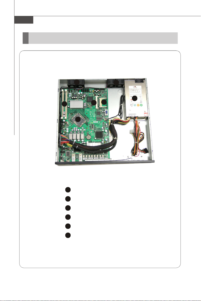
System Overview
Top View
1
CPU Socket
Memory DIMM Slots
CompactFlash Socket
Mini PCI Slot
SSI EPS 1U Power Supply
Axial Fans
1-2
Page 11
2
3
4
5
6
7
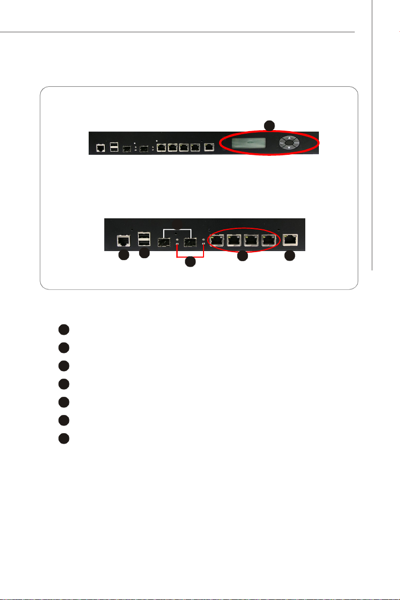
Front View
23745
6
Front Bezel
1
Front Panel LCM (Optional)
Getting Started
1
Serial Console Port
USB Ports
GbE Fiber SFP LAN Ports
Status LEDs of Fiber SFP LAN
GbE RJ-45 LAN Ports (with bypass function)
GbE RJ-45 LAN Port
1-3
Page 12
MS-92A2 Server
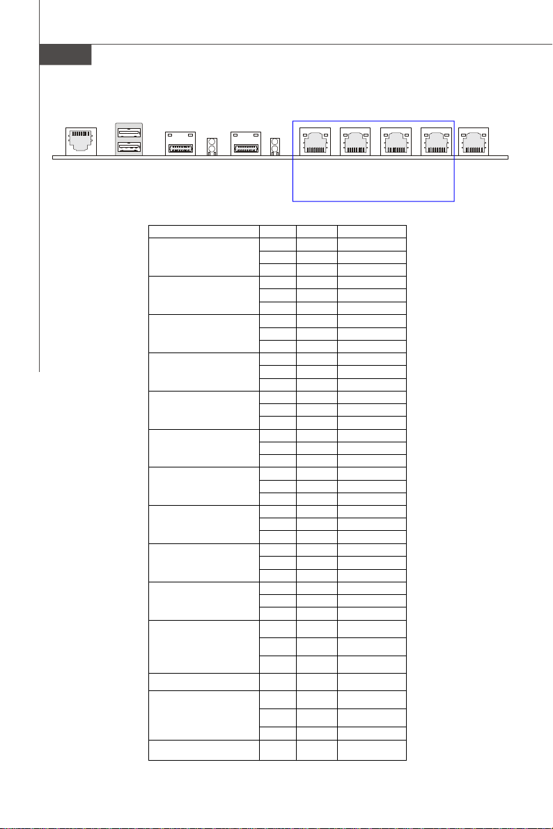
USB Ports
LED2
LED1
COM1 Serial
Console Port
1-4
LAN7 GbE
Fiber SFP
LAN
LAN6 GbE
Fiber SFP
LAN
LED Color State Description
RJ45 NIC 1 Linkage
Yellow On LAN linked
Yellow Blinking LAN accessing
Off Off No LAN linked
RJ45 NIC 1 Mode
Amber On Gigabit mode
Green On 100M mode
Off Off 10M mode
RJ45 NIC 2 Linkage
Yellow On LAN linked
Yellow Blinking LAN accessing
Off Off No LAN linked
RJ45 NIC 2 Mode
Amber On Gigabit mode
Green On
Off Off 10M mode
RJ45 NIC 3 Linkage
Yellow On LAN linked
Yellow Blinking LAN accessing
Off Off No LAN linked
RJ45 NIC 3 Mode
Amber On Gigabit mode
Green On
Off Off 10M mode
RJ45 NIC 4 Linkage
Yellow On LAN linked
Yellow Blinking LAN accessing
Off Off No LAN linked
RJ45 NIC 4 Mode
Amber On Gigabit mode
Green On
Off Off 10M mode
RJ45 NIC 5 Linkage
Yellow On LAN linked
Yellow Blinking LAN accessing
Off Off No LAN linked
RJ45 NIC 5 Mode
Amber On Gigabit mode
Green On
Off Off 10M mode
Fiber SFP NIC 6 Linkage
Green On LAN linked
Green Blinking LAN accessing
Off Off No LAN linked
Fiber SFP NIC 6 Mode Yellow On Gigabit mode
Fiber SFP NIC 7 Linkage
Green On LAN linked
Green Blinking LAN accessing
Off Off No LAN linked
Fiber SFP NIC 7 Mode Yellow On Gigabit mode
LAN5 LAN4
GbE RJ-45 LAN
(Bypass Pair 2)
100M mode
100M mode
100M mode
100M mode
LAN3 LAN2
GbE RJ-45 LAN
(Bypass Pair 1)
LAN1 GbE
RJ-45 LAN
Page 13
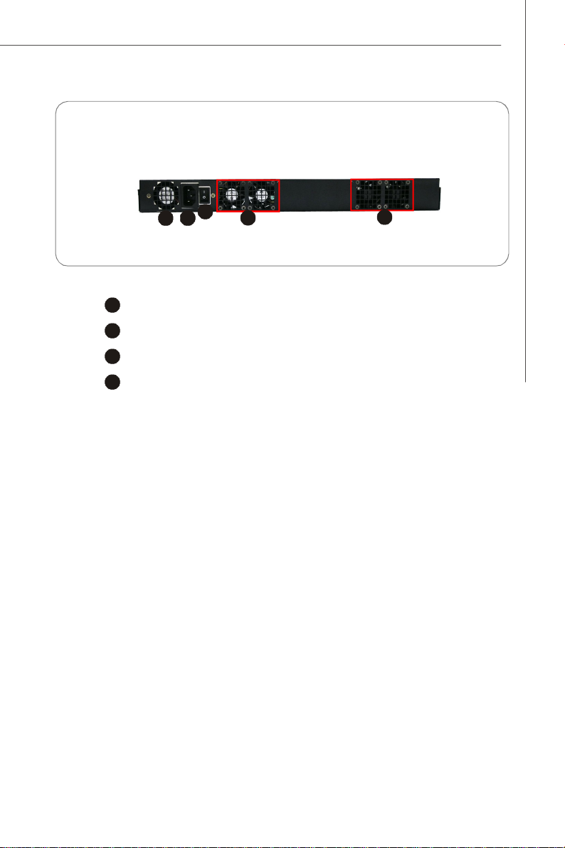
Rear View
2
3
4
4
2
3
4
1
SSI EPS 1U Power Supply
Power Connector
Power Switch
Axial Fans
Getting Started
1
1-5
Page 14
MS-92A2 Server
Mainboard Specifications
Processor
- Intel Pentium 4 (Quad-Core Kentsfield/Yorkfield & Dual-Core Conroe/
Wolfdale/Celeron D) processors in LGA775 package
FSB
- 800/1066/1333MHz
Chipset
- Northbridge: Intel 3210 / 3200 chipset
- Southbridge: Intel ICH9 chipset
Memory
- 2 unbuffered non-ECC DDR2 667/800 DIMM slots (240pin/1.8V)
- Up to 8GB memory capacity
LAN
- Supports 6 PCI-E Gb LAN by Intel 82575 (including 2-pair RJ45 LAN
bypass and 1-pair fiber LAN)
- Supports 1 RJ45 LAN by Intel 82566 for LAN management
IDE
- 1 IDE port by JMicron JMB368 (44-pin connector)
- Supports ATA133/100/66
- ATA/ATAPI-7 compliant
1-6
CF
- 1 Compact Flash Type socket by JMicron JMB368
- Supports Ultra DMA 66/100/133 mode
SATA
- 4 SATAII ports by ICH9
- Supports 4 SATAII devices
- Supports up to 3Gb/s data transfer rate
Page 15
Graphics
- XGI Z7 graphics controller
Onboard I/O
Front I/O
- 1 serial console port (RJ-45 jack)
- 2 USB 2.0 ports
- 2 NIC fiber LAN ports with link/activity LEDs
- 5 individual RJ-45 Gigabit LAN ports with LEDs
Onboard Connectors
- 1 USB 2.0 connector (2 ports)
- 1 serial port connector
- 1 D-Sub VGA connector
- 1 mouse/keyboard connector
- 1 SPI Flash ROM connector (for debugging)
Slot/Golden Finger
- 1 Mini PCI slot
- 2 PCI Express x4 golden finger
Regulations
- FCC, CE
Getting Started
Dimension
- 239mm X 364.5mm
Mounting
- 9 mounting holes
1-7
Page 16
MS-92A2 Server
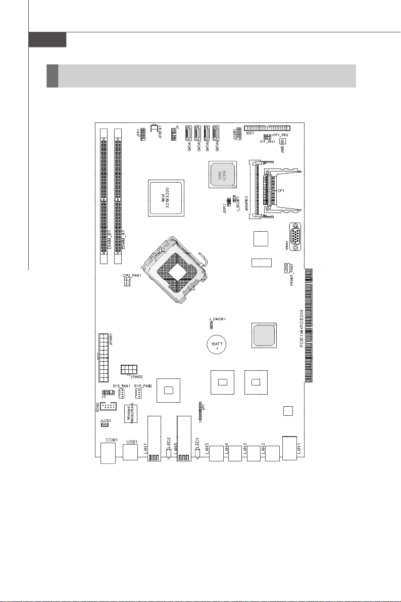
Mainboard Layout
1-8
3200 Network (MS-91A2 V1.X) Server Board
Page 17
Getting Started
Watch Dog Timer Setting
MS-91A2 watchdog timer is using Super I/O Winbond W83627EHG.
Setup procedures
A.Enter super I/O configuration mode -
mov dx, 04eh
mov al, 087h
out dx, al
out dx, al
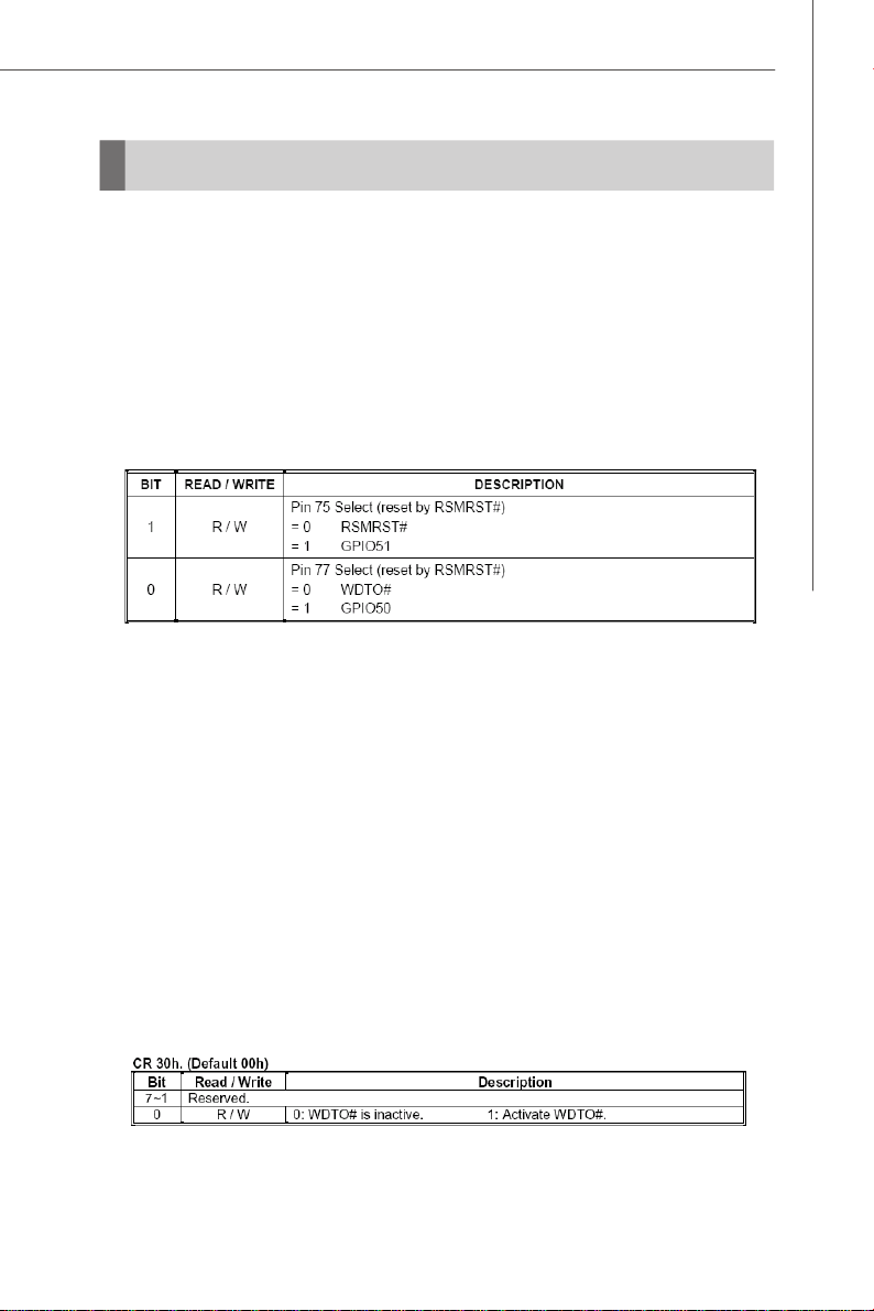
B. Set pin 77 to WDTO# function
mov dx,04eh
mov al,02Dh;; ;Register 2Dh
out dx,al
inc dx
in al,dx
and al,0FEh ;Config Bit 0 As 0
out dx,al ;Config PIN 77 as WDTO#
C. Select Logical Device 8
mov dx, 04eh
mov al, 07h
out dx, al ;point to Logical Device Number Register
inc dx
mov al, 08h ;select Logical Device 8
out dx, al
D. Enable watchdog timer
Activate WDTO#
1-9
Page 18
MS-92A2 Server
mov dx, 04eh ;CR 30h: bit 0 fill in 1
mov al, 030h
out dx, al
inc dx
mov al, 01h
out dx, al
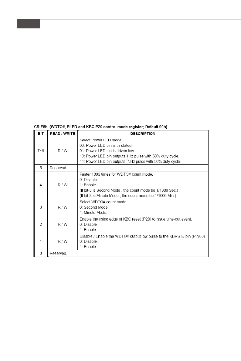
; Setup WDTO# count mode
; Set bit 4 and bit 3 by request
; Set bit 2 to 0
; Set bit 1 to 1
1-10
Page 19
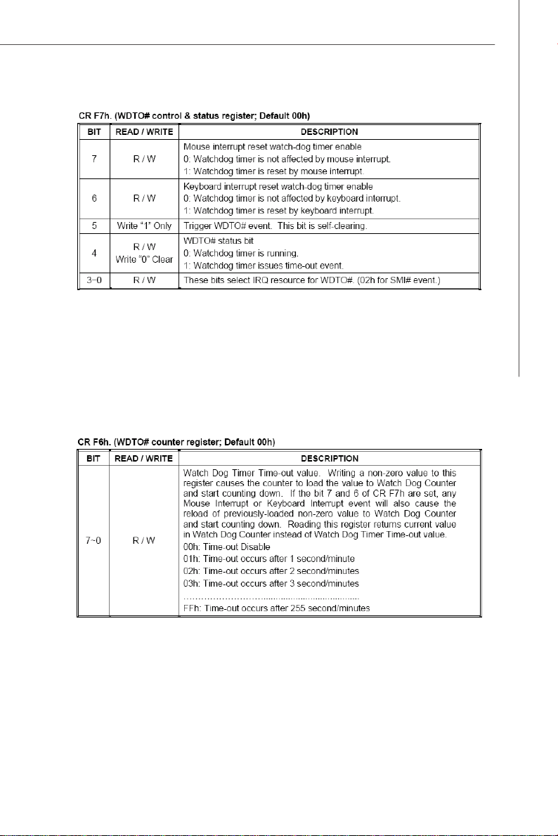
mov dx, 04eh ;CR F7h: bit 4 fill 0 (clear event)
mov al, 0f7h
out dx, al
inc dx
in al,dx
and al, 0efh
out dx, al
;CR F6h: bit0~7 fill in counter time
Getting Started
E. Exit configuration mode
mov dx, 04eh
mov al, 0aah
out dx, al
1-11
Page 20

MS-92A2 Server
1-12
Page 21
Hardware Setup
Chapter 2
Hardware Setup
Refer to the system assembly flowchart and the chart
below to determine the proper sequence of removing
or installing components to the server.
MS-92A2
Mainboard Hardware
System Assembly
Rack Mounting
CPU, Memory, Power Supply, Back
Panel, Connector, Jumper, Slot
Chassis Cover
CPU, Cooler
Memory
Expansion Card
Hard Disk Drives
Rail Set
Rack Mounting
2-1
Page 22
MS-92A2 Server
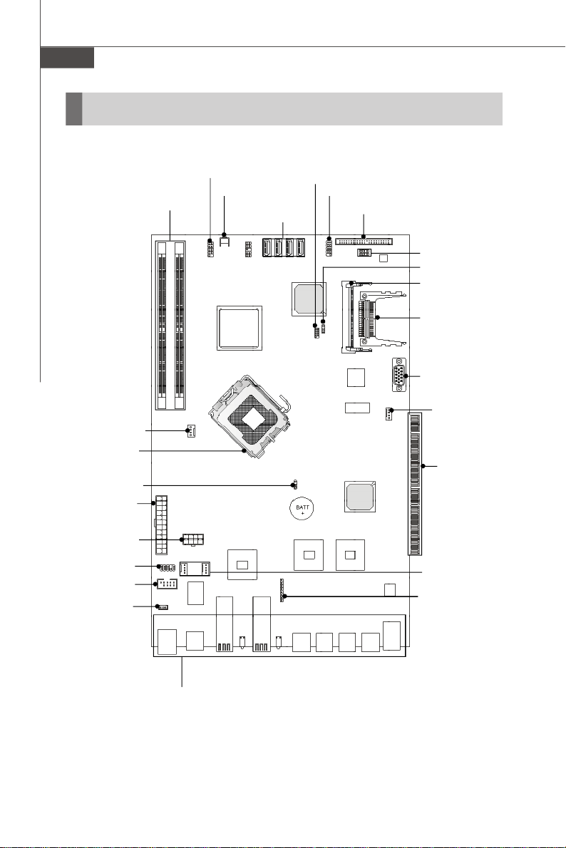
Quick Components Guide
DIMM Slots,
CPU_FAN1, p.2-13
CPU, p.2-3
J_CMOS1, p.2-17
JPWR1, p.2-5
JPWR2, p.2-5
J3, p.2-16
COM2, p.2-13
JLCD1, p.2-15
p.2-4
JFP1, p.2-15
JPBTN1, p.2-15
JSPI1, p.2-12
SATA1~4,
p.2-12
JUSB1, p.2-14
IDE1, p.2-11
JCFV_SEL1,
JCF_SEL1,
p.2-19
J_BOOT1, p.2-17
MINIPCI1, p.2-18
CF1, p.2-19
VGA1, p.2-14
FRONT_FAN1,
p.2-13
Golden Finger,
p.2-18
SYS_FAN1~2,
p.2-13
JP1, p.2-16
2-2
Front Panel
I/O, p.2-6
Page 23

Hardware Setup
CPU (Central Processing Unit)
This mainboard supports Intel® Pentium 4 (Quad-Core Kentsfield/Yorkfield & DualCore Conroe/Wolfdale/Celeron D) processors in LGA775 package. When you install
the CPU, make sure that you install the cooler to prevent overheating. If you
do not have the CPU cooler, consult your dealer before turning on the computer.
Important
Overheating
Overheating will seriously damage the CPU and system. Always make sure
the cooling fan can work properly to protect the CPU from overheating. Make
sure that you apply an even layer of thermal paste (or thermal tape) between
the CPU and the heatsink to enhance heat dissipation.
Replaceing the CPU
While replacing the CPU, always turn off the power supply or unplug the
power supply’s power cord from the grounded outlet first to ensure the safety
of CPU.
Introduction to LGA 775 CPU
The pin-pad side of LGA 775
CPU.
Alignment Key Alignment Key
Yellow triangle is the Pin 1 indicator
The surface of LGA 775 CPU.
Remember to apply some thermal paste on it for better heat
dispersion.
Yellow triangle is the Pin 1 indicator
2-3
Page 24

MS-92A2 Server
Memory
These DIMM slots are intended for system memory modules.
DDR2
240-pin, 1.8V
64x2=128 pin 56x2=112 pin
Installing Memory Modules
1. Locate the DIMM slots on the mainboard. Flip open the retaining clip at each side
of the DIMM slot.
2. Align the notch on the DIMM with the key on the slot. Insert the DIMM vertically into
the DIMM slot. Then push it in until the golden finger on the DIMM is deeply inserted
in the DIMM slot. The retaining clip at each side of the DIMM slot will automatically
close if the DIMM is properly seated.
Important
You can barely see the golden finger if the DIMM is properly inserted in the
DIMM slot.
3. Manually check if the DIMM has been locked in place by the retaining clips at the
sides.
4. Follow the same procedures to install more DIMMs if necessary.
Volt
Notch
2-4
Page 25

Hardware Setup
Power Supply
24-Pin System Power Connector: JPWR1
This connector allows you to connect a 24-pin power supply. To
connect the 24-pin power supply, make sure the power supply
connector is inserted in the proper orientation and the pins are
aligned. Then push down the power supply firmly into the connector.
You may use the 20-pin power supply as well. If you’d like to use the
20-pin power supply, please align your power supply connector
with pin 1 & pin 13. There is also a foolproof design on pin 11, 12, 23
& 24 to avoid wrong installation.
Pin Definition
JPWR1
24 13
112
PIN SIGNAL
1 +3.3V
2 +3.3V
3 GND
4 +5V
5 GND
6 +5V
7 GND
8 PWR OK
9 5VSB
10 +12V
11 +12V
12 +3.3V
PIN SIGNAL
13 +3.3V
14 -12V
15 GND
16 PS-ON#
17 GND
18 GND
19 GND
20 Res
21 +5V
22 +5V
23 +5V
24 GND
pin 12
pin 13
8-Pin CPU Power Connector: JPWR2
This connector provides 12V power output to the CPU.
JPWR2
5
8
1
4
PIN SIGNAL
1 GND
2 GND
3 GND
4 GND
Pin Definition
PIN SIGNAL
5 +12V
6 +12V
7 +12V
8 +12V
Important
1. Make sure that all connectors are connected to proper power supplies to
ensure stable operation of the mainboard.
2. Power supply of 350 watts (and above) is highly recommended for system
stability.
2-5
Page 26

MS-92A2 Server
LAN Bypass Disable
LAN Bypass Enable
Front Panel I/O
USB Ports
LED2
LED1
COM1 Serial
Console Port
LAN7 GbE
Fiber SFP
LAN
LAN
WAN
LAN
LAN6 GbE
Fiber SFP
LAN
WAN
LAN5 LAN4
GbE RJ-45 LAN
(Bypass Pair 2)
LAN
WAN
LAN3 LAN2
GbE RJ-45 LAN
(Bypass Pair 1)
LAN
WAN
NOTE: LAN bypass function only works in the event of AC power down.
USB Port
The USB (Universal Serial Bus) port is for attaching USB devices such as keyboard,
mouse, or other USB-compatible devices.
GbE LAN Ports
LAN6 ~ LAN7: GbE SFP LAN port
Insert your fiber SFP (Small Form-Factor Pluggable) transceiver module into the Mini
GBIC SFP port and connect the optical fiber network cable to the SFP module.
LAN1 GbE
RJ-45 LAN
2-6
Page 27

Hardware Setup
LAN1 ~ LAN5: GbE RJ-45 LAN port
The standard RJ-45 jack is for connection to Local Area Network (LAN). You can
connect a network cable to it.
Link/Active Indicator
RJ-45 LAN Jack
Mode Indicator
RJ45 NIC 1 Linkage
LED Color State Description
RJ45 NIC 1 Mode
RJ45 NIC 2 Linkage
RJ45 NIC 2 Mode
RJ45 NIC 3 Linkage
RJ45 NIC 3 Mode
RJ45 NIC 4 Linkage
RJ45 NIC 4 Mode
RJ45 NIC 5 Linkage
RJ45 NIC 5 Mode
Fiber SFP NIC 6 Linkage
Fiber SFP NIC 6 Mode Yellow On Gigabit mode
Fiber SFP NIC 7 Linkage
Fiber SFP NIC 7 Mode Yellow On Gigabit mode
Yellow On LAN linked
Yellow Blinking LAN accessing
Off Off No LAN linked
Amber On Gigabit mode
Green On 100M mode
Off Off 10M mode
Yellow On LAN linked
Yellow Blinking LAN accessing
Off Off No LAN linked
Amber On Gigabit mode
Green On
Off Off 10M mode
Yellow On LAN linked
Yellow Blinking LAN accessing
Off Off No LAN linked
Amber On Gigabit mode
Green On
Off Off 10M mode
Yellow On LAN linked
Yellow Blinking LAN accessing
Off Off No LAN linked
Amber On Gigabit mode
Green On
Off Off 10M mode
Yellow On LAN linked
Yellow Blinking LAN accessing
Off Off No LAN linked
Amber On Gigabit mode
Green On
Off Off 10M mode
Green On LAN linked
Green Blinking LAN accessing
Off Off No LAN linked
Green On LAN linked
Green Blinking LAN accessing
Off Off No LAN linked
100M mode
100M mode
100M mode
100M mode
2-7
Page 28

MS-92A2 Server
LAN Bypass Definition
Bypass setting in BIOS
Power
BIOS Bypass Setting Bypass Behavior
Status
On Bypass mode after power on
Bypass mode after power off
Off
(All segment or by each segment are controllable)
Pass Through Behavior: A
Disable A
Enable B
Disable A
Enable B
Bypass Behavior: B
2-8
Page 29

Programming Guide
LPC I/O address: 5E
Power ON/OFF State Bypass Control Status Register
Set/Read bypass mode
Default Value: 0xD0 (Base on Customer Demand)
Power ON/OFF State Bypass Control Status Register
I/O Address: 5E
7 6 5 4 3 2 1 0
X X X X R/W R/W R/W R/W
Not
Not
Not
Not
Used
Used
Used
Bit Definition
Power ON/OFF State Bypass Control Status Register
Bit Field Name Value
3:0
Segment
1 to 4
Segment 4 Segment 3 Segment 2 Segment 1
Used
Segment control bit. Each bit corresponds to a specific segment
numbered 1 thru 4.
Write:
1: Force Bypass
0: Force Pass Through
Read:
1: Bypass Mode
0: Pass Through Mode
Hardware Setup
PWRON Signal Action
Segment Signal Name Description Type Bypass Pass Through
Segment 1
Segment 2
RELAY_SET1# Enable LAN 3~4 bypass Output 1 0
RESET_RESET1# Enable LAN 3~4 bypass Output 0 1
RELAY_SET2# Enable LAN 1~2 bypass Output 1 0
RESET_RESET2# Enable LAN 1~2 bypass Output 0 1
PWROFF Signal Action
Segment Signal Name Description Type Bypass Pass Through
Segment 3
Segment 4
RELAY_SET1# Enable LAN 3~4 bypass Output 1 0
RESET_RESET1# Enable LAN 3~4 bypass Output 0 1
RELAY_SET2# Enable LAN 1~2 bypass Output 1 0
RESET_RESET2# Enable LAN 1~2 bypass Output 0 1
2-9
Page 30

MS-92A2 Server
Sample code to access IO Port 5Eh
IO Port 5Eh High Low
Bit 0/1 POWER ON Lan3-4/Lan1-2 Bypass POWER ON Lan3-4/Lan1-2 Pass Through
Bit 2/3 POWER OFF Lan3-4/Lan1-2 Bypass POWER OFF Lan3-4/Lan1-2 Pass Through
Set Bit 0 and 1 to High
mov dx, 5Eh
in al, dx Read 5Eh's value to al
and al, 0fch Clear Bit 0 and 1
or al, 03h Set Bit 0 and 1 to high
out dx, al Write to 5Eh
Set Bit 0 and 1 to Low
mov dx, 5Eh
in al, dx Read 5Eh's value to al
and al, 0fch Clear Bit 0 and 1
out dx, al Write to 5Eh
Set Bit 2 and 3 to High
mov dx, 5Eh
in al, dx Read 5Eh's value to al
and al, 0f3h Clear Bit 2 and 3
or al, 0ch Set Bit 2 and 3 to high
out dx, al Write to 5Eh
Set Bit 2 and 3 to Low
mov dx, 5Eh
in al, dx Read 5Eh's value to al
and al, 0f3h Clear Bit 2 and 3
out dx, al Write to 5Eh
2-10
Page 31

Hardware Setup
Connector
IDE Connector: IDE1
This connector supports IDE hard disk drives, optical disk drives and other IDE devices.
IDE1
Important
If you install two IDE devices on the same cable, you must configure the drives
separately to master / slave mode by setting jumpers. Refer to IDE device’s
documentation supplied by the vendors for jumper setting instructions.
2-11
Page 32

MS-92A2 Server
SPI Flash ROM Connector: JSPI1
This connector is used to flash SPI flash ROM.
Pin Definition
Pin Description Pin Description
1 VCC3_SB 2 VCC3_SB
3 SPI_MISO_F 4 SPI_MOSI_F
5 SPI_CS0_F# 6 SPI_CLK_F
7 GND 8 GND
9 SPI_HOLD# 10 NC
9
10
JSPI1
1
2
Serial ATA Connector: SATA1 ~ SATA4
This connector is a high-speed Serial ATA interface port. Each connector can connect to one Serial ATA device.
SATA1
SATA2
SATA3
SATA4
Important
Please do not fold the Serial ATA cable into 90-degree angle. Otherwise,
data loss may occur during transmission.
2-12
Page 33

Hardware Setup
Serial Port Connector: COM2
This connector is a 16550A high speed communications port that sends/receives 16
bytes FIFOs. You can attach a serial device to it through the optional serial port
bracket.
Pin Definition
PIN SIGNAL DESCRIPTION
1 DCD Data Carry Detect
2 SIN Serial In or Receive Data
3 SOUT Serial Out or Transmit Data
4 DTR Data Terminal Ready
5 GND Ground
6 DSR Data Set Ready
7 RTS Request To Send
8 CTS Clear To Send
9 VCC_COM Power Source
8
2
COM 2
9
1
Fan Power Connector: CPU_FAN1, SYS_FAN1/2, FRONT_FAN1
The fan power connectors support system cooling fan with +12V. When connecting
the wire to the connectors, always note that the red wire is the positive and should
be connected to the +12V; the black wire is Ground and should be connected to GND.
If the mainboard has a System Hardware Monitor chipset onboard, you must use a
specially designed fan with speed sensor to take advantage of the CPU fan control.
C
S
O
E
N
N
T
+
S
G
R
1
O
N
O
2
R
D
V
L
CPU_FAN1
SYS_FAN1/2,
FRONT_FAN1
GND
+1 2V
SENS O R
CONTROL
Important
1.Please refer to the recommended CPU fans at processor’s official website
or consult the vendors for proper CPU cooling fan.
2.Users are suggested to enter the BIOS Setup Utility to set up the Smart Fan
Control function.
2-13
Page 34

MS-92A2 Server
VGA Connector: VGA1
The DB15-pin female connector is provided for monitor.
Front USB Connector: JUSB1
This connector, compliant with Intel® I/O Connectivity Design Guide, is ideal for connecting high-speed USB interface peripherals such as USB HDD, digital cameras,
MP3 players, printers, modems and the like.
Pin Definition
PIN SIGNAL PIN SIGNAL
1 VCC 2 VCC
3 USB0- 4 USB15 USB0+ 6 USB1+
7 GND 8 GND
9 Key (no pin) 10 USBOC
9
10
JUSB1
1
2
USB 2.0 Bracket
(Optional)
Important
Note that the pins of VCC and GND must be connected correctly to avoid
possible damage.
2-14
Page 35

Hardware Setup
LCD Module Connector: JLCD1
This connector is used to connect TTL UART LCD Module.
Pin Definition
JLCD1
1
PIN SIGNAL
1 +5V
2 RX
3 GND
4 TX
NMI Button: JPBTN1
When the Operating System suffers from critical errors and consequently hangs,
users may press this NMI (Non Maskable Interrupt) button to log the system errors.
JPBTN1
Front Panel Connector: JFP1
This connector is for electrical connection to the front panel switches and LEDs and
is compliant with Intel® Front Panel I/O Connectivity Design Guide.
HDD
Reset
LED
Switch
--
+
+
- -
+
+
Power
LED
1
2
JFP1
9
10
Power
Switch
JFP1 Pin Definition
PIN SIGNAL DESCRIPTION
1 HD_LED + Hard disk LED pull-up
2 FP PWR/SLP MSG LED pull-up
3 HD_LED - Hard disk active LED
4 FP PWR/SLP MSG LED pull-up
5 RST_SW - Reset Switch low reference pull-down to GND
6 PWR_SW + Power Switch high reference pull-up
7 RST_SW + Reset Switch high reference pull-up
8 PWR_SW - Power Switch low reference pull-down to GND
9 RSVD_DNU Reserved. Do not use.
2-15
Page 36

MS-92A2 Server
Keyboard/Mouse Connector: J3
This connector is used to connect a mouse/keyboard.
Pin Definition
J3
10
2
9
1
PIN SIGNAL
1 KBMS_Power
2 KBMS_Power
3 KEY
4 NC
5 GND
6 GND
7 MSCLK
8 KBCLK
9 MSDAT
10 KBDAT
CPLD Data Reflash Pinheader:JP1
JP1
1
8
2-16
Pin Definition
Pin Description Pin Description
1 VCC 2 TDD
3 TDI 4 IspEN
5 TRST 6 TMS
7 GND 8 TCK
Page 37

Hardware Setup
Jumper
BIOS Recovery Jumper: J_BOOT1
Users can short connect pin#2-3 to recover the system BIOS with a Recovery
Floppy. When the system is done with the job, the buzzer will beep to remind the user
to set the jumper to its normal state (pin#1-2 short connected).
1
J_BOOT1
1 3
Normal
1 3
Recovery
Clear CMOS Jumper: J_CMOS1
There is a CMOS RAM onboard that has a power supply from an external battery to
keep the data of system configuration. With the CMOS RAM, the system can automatically boot OS every time it is turned on. If you want to clear the system configuration,
set the jumper to clear data.
1
J_CMOS1
1 3
Keep Data
1 3
Clear Data
Important
You can clear CMOS by shorting 2-3 pin while the system is off. Then return
to 1-2 pin position. Avoid clearing the CMOS while the system is on; it will
damage the mainboard.
2-17
Page 38

MS-92A2 Server
Slot / Golden Finger
Golden Finger
PCI Express x4
PCI Express x4
Mini PCI Slot
Mini PCI Slot
Important
When adding or removing expansion cards, make sure that you unplug the
power supply first. Meanwhile, read the documentation for the expansion
card to configure any necessary hardware or software settings for the expansion card, such as jumpers, switches or BIOS configuration.
2-18
Page 39

Hardware Setup
CompactFlash Card Slot: CF1 (Optional)
This CompactFlash slot shares one channel of the IDE controller. You can install one
CompactFlash typeI / type II device.
CF1
CF Mode Selecting Jumper: JCF_SEL1
This jumper is used to select Master/Slave mode of the CF device.
1
JCF_SEL1
1
3
Master
1
3
Slave
CF Voltage Selecting Jumper: JCFV_SEL1
This jumper is used to select the operating voltage of the CF device.
1
JCFV_SEL1
1
3
VCC3
1
3
VCC5
Important
* The CF1 slot and the IDE1 connector shares and uses the same channel. CF1
and IDE1 can support up to 2 IDE devices without CF device or 1 IDE device
with 1 CF device.
* If you install two IDE devices, you must configure the second drive to Slave
mode by setting its jumper. Refer to the hard disk documentation supplied by
hard disk vendors for jumper setting instructions.
* If you install one IDE device with ATA133 IDE cable and one CF device, you
must configure the CF drive to Master mode by setting jumper JCF_SEL1.
CF only supports Master mode by using ATA133 IDE cable. CF only supports
Slave mode by using ATA33 IDE cable.
2-19
Page 40

MS-92A2 Server
START
System Assembly Flowchart
The following flowchart shows basic system assembly procedures. Please note
that always wear anti-static gloves when handling electrical components and exercise caution during the installation process. For more information, contact your local
dealer or experienced technician.
Remove the chassis cover
Install hard disk drives
Install the CPU & heatsink
Install memory modules
Install PCI expansion cards
(optional)
2-20
Check if the power connectors
are properly connected
Replace the chassis cover
FINISH
Page 41

System Assembly
Chassis Cover
1. Unscrew the chassis cover.
2. Slide the chassis cover
backwards.
Hardware Setup
3. Lift the chassis cover up to remove it from the chassis.
4. Follow the above procedures in reverse order to replace the chassis cover if
necessary.
Important
Before you remove or install any components, make sure the system is not
turned on or connected to the AC power.
2-21
Page 42

MS-92A2 Server
CPU, Heatsink, and Fan Duct
1. On top of the CPU is a fan duct designed
to enhance heat dissipation of the CPU.
Unscrew and remove the fan duct before installing the CPU.
2. Locate the CPU socket. The CPU socket
has a plastic cap on it to protect the
contact from damage. Before installing the CPU, always cover it to protect the socket pins.
3. Remove the plastic cap from the load
plate. The pins of the socket reveal.
4. Raise the load lever up to its full extent.5. Open the load plate.
2-22
Page 43

Hardware Setup
6. After confirming the CPU direction (indicated below with red circles) for correct
mating, put down the CPU in the socket housing frame. Note that the alignment
keys are matched.
7. Visually inspect if the CPU is seated well into the socket. If not, take out the CPU
with pure vertical motion and reinstall.
Alignment Key
Yellow triangle is the Pin 1 indicator
8. Cover the load plate onto the package.
9. Press down the load lever lightly onto the load plate and then secure the lever
with the hook under the retention tab.
10.Place the heatsink on top of the CPU and secure the screws on both sides.
2-23
Page 44

MS-92A2 Server
Memory
1. Locate the DIMM slots on the mainboard. Flip open the retaining clip at each side
of the DIMM slot.
2. Align the notch on the DIMM with the break on the slot. Insert the DIMM vertically
into the DIMM slot. Then push it in until the golden finger on the DIMM is deeply
inserted in the DIMM slot. The retaining clip at each side of the DIMM slot will
automatically close.
3. Follow the same procedures to install
more memory modules if necessary.
5. Screw to secure the fan duct.
2-24
4. Replace the fan duct on top of the
heatsink and the memory DIMMs.
Page 45

Hardware Setup
Hard Disk Drive
1. Unscrew the HDD tray.
2. Remove the HDD tray from the chassis.
3. Fit the HDD into the tray and align the screw holes on the sides. Screw the HDD
firmly to the tray.
4. The system power supply provides various types of power cables. Pick out the
SATA power cable and connect it to the SATA HDD.
2-25
Page 46

MS-92A2 Server
5. Connect one end of the SATA signal cable to the SATA HDD and connect the other
end to the SATA connector on the mainboard.
6. Put the HDD set back to the chassis.
7. Secure it with two screws.
2-26
Page 47

Hardware Setup
Rack Mounting
Chassis Ears & Rails
1. The chassis rails and rack rails have been assembled together beforehand. The first thing to do
with the rail set is to take the chassis rails off the
rack rails.
NOTE:
Only the service personnel are
allowed to handle the rail set.
2. Pull the chassis rail gently out until the locking tab locks the rail.
3. Simultaneously push open the locking tab and pull out the chassis rail. The chassis rail should slide easily off the rack rail.
4. Follow the same procedures to disassemble the second chassis rail.
NOTE: The chassis rail is designed with a locking tab which can (1) hold
the system firmly to the rack, and (2) lock the system halfway without sliding
out of the rack rails.
2-27
Page 48

MS-92A2 Server
5. Place the chassis ear and rail on the chassis with screw holes aligned.
6. Secure the chassis ear with 3 screws.
7. Fasten the rail onto the chassis with 3 screws.
8. Follow the same procedures to install the second chassis ear and rail.
2-28
Page 49

Hardware Setup
Rack Rails
1. Release the L-shaped bracket from the rack rail. Adjust the length of the rack rail
to make sure the rail length fits the rack. Screw the L-shaped bracket back to the
rail.
2. Locate the triangle mark on the rack and install 2 screw holders to the rack as
shown.
3. Secure the rack rail to the rack with two screws on the front and two on the rear.
4. Follow the same procedures to install the second rack rail.
2-29
Page 50

MS-92A2 Server
Rack Mounting
1. To slide the system into the rack, first align the chassis rails with the rack rails
and push the system inwards until the locking tab clicks.
2. Simultaneously push open the locking tabs on both sides of the chassis rails and
push the system inwards. The system should slide easily into the rack.
Note: The chassis rail is designed with a locking tab which can (1) hold the
system firmly to the rack, and (2) lock the system halfway without sliding out
of the rack rails.
3. Screw the system firmly to the rack.
2-30
Page 51

Chapter 3
BIOS Setup
This chapter provides information on the BIOS Setup
program and allows you to configure the system for
optimum use.
You may need to run the Setup program when:
² An error message appears on the screen during the
system booting up, and requests you to run SETUP.
² You want to change the default settings for cus-
tomized features.
BIOS Setup
3-1
Page 52

MS-92A2 Server
Entering Setup
Power on the computer and the system will start POST (Power On Self Test) process.
When the message below appears on the screen, press <Del> key to enter Setup.
Press Del to enter SETUP
If the message disappears before you respond and you still wish to enter Setup,
restart the system by turning it OFF and On or pressing the RESET button. You may
also restart the system by simultaneously pressing <Ctrl>, <Alt>, and <Delete> keys.
Important
1.The items under each BIOS category described in this chapter are under
continuous update for better system performance. Therefore, the description may be slightly different from the latest BIOS and should be held for
reference only.
2.Upon boot-up, the 1st line appearing after the memory count is the BIOS
version. It is usually in the format:
3-2
A92A2IMS V1.0 033108 where:
1st digit refers to BIOS maker as A = AMI, W = AWARD, and P =
PHOENIX.
2nd - 5th digit refers to the model number.
6th digit refers to the chipset as I = Intel, N = nVidia, and V = VIA.
7th - 8th digit refers to the customer as MS = all standard customers.
V1.0 refers to the BIOS version.
033108 refers to the date this BIOS was released.
Page 53

BIOS Setup
Control Keys
<↑> Move to the previous item
<↓> Move to the next item
<←> Move to the item in the left hand
< →> Move to the item in the right hand
<Enter> Select the item
<Esc> Jumps to the Exit menu or returns to the main menu from a
submenu
<+/PU> Increase the numeric value or make changes
<-/PD> Decrease the numeric value or make changes
<F9> Load Optimized Defaults
<F8> Load Fail-Safe Defaults
<F10> Save all the CMOS changes and exit
Getting Help
After entering the Setup menu, the first menu you will see is the Main Menu.
Main Menu
The main menu lists the setup functions you can make changes to. You can use the
arrow keys ( ↑↓ ) to select the item. The on-line description of the highlighted setup
function is displayed at the bottom of the screen.
Sub-Menu
If you find a right pointer symbol (as shown in the right view)
appears to the left of certain fields that means a sub-menu
can be launched from this field. A sub-menu contains additional options for a field parameter. You can use arrow keys ( ↑↓ ) to highlight the
field and press <Enter> to call up the sub-menu. Then you can use the control keys
to enter values and move from field to field within a sub-menu. If you want to return
to the main menu, just press the <Esc >.
General Help <F1>
The BIOS setup program provides a General Help screen. You can call up this screen
from any menu by simply pressing <F1>. The Help screen lists the appropriate keys
to use and the possible selections for the highlighted item. Press <Esc> to exit the
Help screen.
3-3
Page 54

MS-92A2 Server
The Menu Bar
Main
Use this menu for basic system configurations, such as time, date etc.
Advanced
Use this menu to set up the items of special enhanced features.
Boot
Use this menu to specify the priority of boot devices.
Security
Use this menu to set supervisor and user passwords.
Chipset
This menu controls the advanced features of the onboard Northbridge and Southbridge.
Exit
This menu allows you to load the BIOS default values or factory default settings into
the BIOS and exit the BIOS setup utility with or without changes.
3-4
Page 55

BIOS Setup
Main
AMI BIOS, Processor, System Memory
These items show the firmware and hardware specifications of your system. Read
only.
System Time
This setting allows you to set the system time. The time format is <Hour> <Minute>
<Second>.
System Date
This setting allows you to set the system date. The date format is <Day>, <Month>
<Date> <Year>.
3-5
Page 56

MS-92A2 Server
Advanced
3-6
Page 57

BIOS Setup
CPU Configuration
Ratio CMOS Setting
This setting controls the multiplier that is used to determine the internal clock
speed of the processor relative to the external or motherboard clock speed. It is
available only when the processor supports this function.
CPU VID
This setting specifies the VID value used by the processor.
Intel(R) Virtualization Tech
Virtualization enhanced by Intel Virtualization Technology will allow a platform
to run multiple operating systems and applications in independent partitions.
With virtualization, one computer system can function as multiple “virtual” systems.
Intel(R) SpeedStep(tm) Tech
EIST (Enhanced Intel SpeedStep Technology) allows the system to dynamically
adjust processor voltage and core frequency, which can result in decreased
average power consumption and decreased average heat production.
3-7
Page 58

MS-92A2 Server
IDE Configuration
SATA Configuration
This setting specifies the operation mode of the SATA ports.
Primary/Secondary/Third/Fourth/Fifth IDE Master/Slave
[Type] Press PgUp/<+> or PgDn/<-> to select
[Manual], [None] or [Auto] type. Note that the
specifications of your drive must match with
the drive table. The hard disk will not work
3-8
Page 59

BIOS Setup
properly if you enter improper information for
this category. If your hard disk drive type is
not matched or listed, you can use [Manual] to
[LBA/Large Mode] Enabling LBA causes Logical Block Ad-
[Block(Multi-Sector Transfer)]Any selection except Disabled determines
[PIO Mode] Indicates the type of PIO (Programmed Input/
[DMA Mode] Indicates the type of Ultra DMA
[S.M.A.R.T.] This allows you to activate the S.M.A.R.T.
[32 Bit Data Transfer] Enables 32-bit communication between
JMicron 36x ATA Controller
This setting enables/disables the onboard JMicron ATA controller.
Super IO Configuration
define your own drive type manually.
dressing to be used in place of Cylinders,
Heads and Sectors
the number of sectors transferred per block
Output)
(Self-Monitoring Analysis & Reporting
Technology) capability for the hard disks. S.
M.A.R.T is a utility that monitors your disk sta
tus to predict hard disk failure. This gives you
an opportunity to move data from a hard disk
that is going to fail to a safe place before the
hard disk becomes offline.
CPU and IDE card
Serial Port 1 Address, Serial Port 2 Address
Select an address and a corresponding interrupt for the serial port 1/2.
3-9
Page 60

MS-92A2 Server
Watch Dog
This setting specifies the Watch Dog Timer action. The [Reboot] option can
reset the system when the Watch Dog Timer is timed out.
Watch Dog Timer (Minutes)
This setting specifies the Watch Dog Timer time out value.
Hardware Health Configuration
These items display the current status of all of the monitored hardware devices/
components such as voltages, temperatures and all fans’ speeds.
3-10
CPUFAN / SYSFAN1 / SYSFAN2 Smart Fann
These settings enable/disable the CPUFAN/SYSFAN1/SYSFAN2 Smart Fan
function. If the Smart Fan function is disabled, the fans will run at full speed.
CPUFAN / SYSFAN1 / SYSFAN2 Target Temp Value
The BIOS will follow the target temperature value to control the fans.
Page 61

BIOS Setup
Power Management
Restore on AC Power Loss
This setting specifies whether your system will reboot after a power failure or
interrupt occurs. Available settings are:
[Power Off] Leaves the computer in the power off state.
[Power On] Leaves the computer in the power on state.
[Last State] Restores the system to the previous status before power
failure or interrupt occurred.
Resume On PME#
When set to [Enabled], this setting allows your system to be awakened from the
power saving modes through any PME (Power Management Event).
Resume On RTC Alarm
When [Enabled], your can set the date and time at which the RTC (real-time
clock) alarm awakens the system from suspend mode.
3-11
Page 62

MS-92A2 Server
Event Log Configuration
View Event Log
Press [Enter] to view the contents of the DMI event log.
Mark All Events as Readd
Press [Enter] and a screen pops up, asking users to confirm whether or not to
clear all DMI event logs immediately. Press [Y] and [Enter], the BIOS will clear all
DMI event logs right away.
Clear Event Log
When this setting is set to [Yes], the DMI event log will be cleared at next POST
stage. Then, the BIOS will automatically set this option to [No].
3-12
Page 63

BIOS Setup
Console Redirection
Remote Access
The setting enables/disables the remote access function. When set to [Enabled],
users may configure the following settings for remote access type and
parameters.
Serial Port Number, Base Address, IRQ, Serial Port Mode
Use these settings to configure ports for remote access.
Flow Control
Flow control is the process of managing the rate of data transmission between
two nodes. It’s the process of adjusting the flow of data from one device to
another to ensure that the receiving device can handle all of the incoming data.
This is particularly important where the sending device is capable of sending
data much faster than the receiving device can receive it.
Redirection After BIOS POST
This setting determines whether or not to keep terminals’ console redirection
running after the BIOS POST has booted.
Terminal Type
To operate the system’s console redirection, you need a terminal supporting
ANSI terminal protocol and a RS-232 null modem cable connected between the
host system and terminal(s). This setting specifies the type of terminal device
for console redirection.
VT-UTF8 Combo Key Support
This setting enables/disables the VT-UTF8 combination key support for ANSI/
VT100 terminals.
3-13
Page 64

MS-92A2 Server
Sredir Memory Display Delay
Use this setting to set the delay in seconds to display memory information.
USB Configuration
Legacy USB Support
Set to [Enabled] if you need to use any USB 1.1/2.0 device in the operating
system that does not support or have any USB 1.1/2.0 driver installed, such as
DOS and SCO Unix.
USB Mass Storage Device Configuration
3-14
Page 65

BIOS Setup
USB Mass Storage Reset Delay
This setting controls the number of seconds the POST waits for the USB
mass storage device after the start unit command is sent.
Emulation Type
This setting enables you to set the type of device you want the USB mass
storage device to emulate.
3-15
Page 66

MS-92A2 Server
Boot
Boot Settings Configuration
3-16
Page 67

BIOS Setup
Quick Boot
Enabling this setting will cause the BIOS power-on self test routine to skip some
of its tests during bootup for faster system boot.
Quiet Boot
This BIOS feature determines if the BIOS should hide the normal POST messages with the motherboard or system manufacturer's full-screen logo.
When it is enabled, the BIOS will display the full-screen logo during the boot-up
sequence, hiding normal POST messages.
When it is disabled, the BIOS will display the normal POST messages, instead of
the full-screen logo.
Please note that enabling this BIOS feature often adds 2-3 seconds of delay to
the booting sequence. This delay ensures that the logo is displayed for a
sufficient amount of time. Therefore, it is recommended that you disable this
BIOS feature for a faster boot-up time.
Bootup Num-Lock
This setting is to set the Num Lock status when the system is powered on.
Setting to [On] will turn on the Num Lock key when the system is powered on.
Setting to [Off] will allow users to use the arrow keys on the numeric keypad.
PS/2 Mouse Support
Select [Enabled] if you need to use a PS/2-interfaced mouse in the operating
system.
Wait For ‘F1’ If Error
When this setting is set to [Enabled] and the boot sequence encounters an
error, it asks you to press F1. If disabled, the system continues to boot without
waiting for you to press any keys.
Hit ‘DEL’ Message Display
Set this option to [Disabled] to prevent the message as follows:
It will prevent the message from appearing on the first BIOS screen when the
computer boots. Set it to [Enabled] when you want to run the BIOS Setup Utility.
Flash Write Protection
This function protects the BIOS from accidental corruption by unauthorized
users or computer viruses. When enabled, the BIOS data cannot be changed
when attempting to update the BIOS with a Flash utility. To successfully update
the BIOS, you will need to disable this Flash Protection function.
Hit Del if you want to run setup
3-17
Page 68

MS-92A2 Server
Boot Device Priority
1st Boot Device
The items allow you to set the sequence of boot devices where BIOS attempts
to load the disk operating system. First press <Enter> to enter the sub-menu.
Then you may use the arrow keys ( ↑↓ ) to select the desired device, then
press <+>, <-> or <PageUp>, <PageDown> key to move it up/down in the
priority list.
Removable Drives
1st Drive, 2nd Drive
This setting allows users to set the priority of the removable devices. First
press <Enter> to enter the sub-menu. Then you may use the arrow keys ( ↑↓ )
to select the desired device, then press <+>, <-> or <PageUp>, <PageDown>
key to move it up/down in the priority list.
3-18
Page 69

BIOS Setup
Security
Supervisor Password / Change Supervisor Password
Supervisor Password controls access to the BIOS Setup utility. These settings allow
you to set or change the supervisor password.
User Password / Change User Password / Clear User Password
User Password controls access to the system at boot. These settings allow you to
set, change, or clear the user password.
3-19
Page 70

MS-92A2 Server
Chipset
USB Functions
This setting specifies the USB function.
USB 2.0 Controller
Set to [Enabled] if you need to use any USB 2.0 device in the operating system that
does not support or have any USB 2.0 driver installed, such as DOS and SCO Unix.
82566 / 82575 LAN Boot
Use these settings to enable/disable Remote Network Boot via PXE.
82566 / 82575 Wake Up From S5
Use these settings to specify whether the system will be awakened from power
saving modes when activity or input signal of onboard LAN is detected.
PWRON LAN1&2 / LAN3&4 Bypass Control, PWROFF LAN1&2 / LAN3&4
Bypass Control
LAN bypass feature removes a single point of failure so that essential business
communication can continue while a network failure is diagnosed and resolved. In
the event of a power, hardware or software failure, Hardware Bypass will automatically activate, allowing network traffic to continue. Traffic between the LAN and
WAN is allowed without interruption. Use these settings to determine the power-on
& power-off LAN bypass mode.
3-20
Page 71

Exit
Save Changes and Exit
Save changes to CMOS and exit the Setup Utility.
BIOS Setup
Discard Changes and Exit
Abandon all changes and exit the Setup Utility.
Discard Changes
Abandon all changes and continue with the Setup Utility.
Load Optimal Defaults
Use this menu to load the default values set by the mainboard manufacturer specifically for optimal performance of the mainboard.
Load Failsafe Defaults
Use this menu to load the default values set by the BIOS vendor for stable system
performance.
3-21
 Loading...