

MSI MS-7865 User Manual
English
11
English
Thank you for choosing the AM1I Series (MS-7865 v2.X) Mini-ITX motherboard. The
AM1I Series motherboards are designed to t the advanced AMD AM1 processor,
the AM1I Series motherboards deliver a high performance and professional desktop
platform solution.
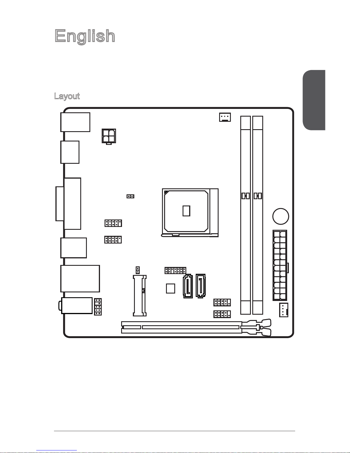
Layout
T:Line-In
M:Line- O ut
B:Mic-I n
PCI_E1
JBAT1 JTPM1
JAUD1
JUSB1
JUSB2
JCI1
SYSF
AN
1
JPWR1
CPUFAN1
JCOM1
SATA1 SATA2
JFP1
JPWR2
BUZ1
DIMM1
DIMM2
T: mouse
B:keybo ard
T: LAN Jack
B: USB 2.0 p ort s
T: VGA
B: DVI -D
USB3.0 po rts
HDMI port
MINI_PC IE_
1
English
12
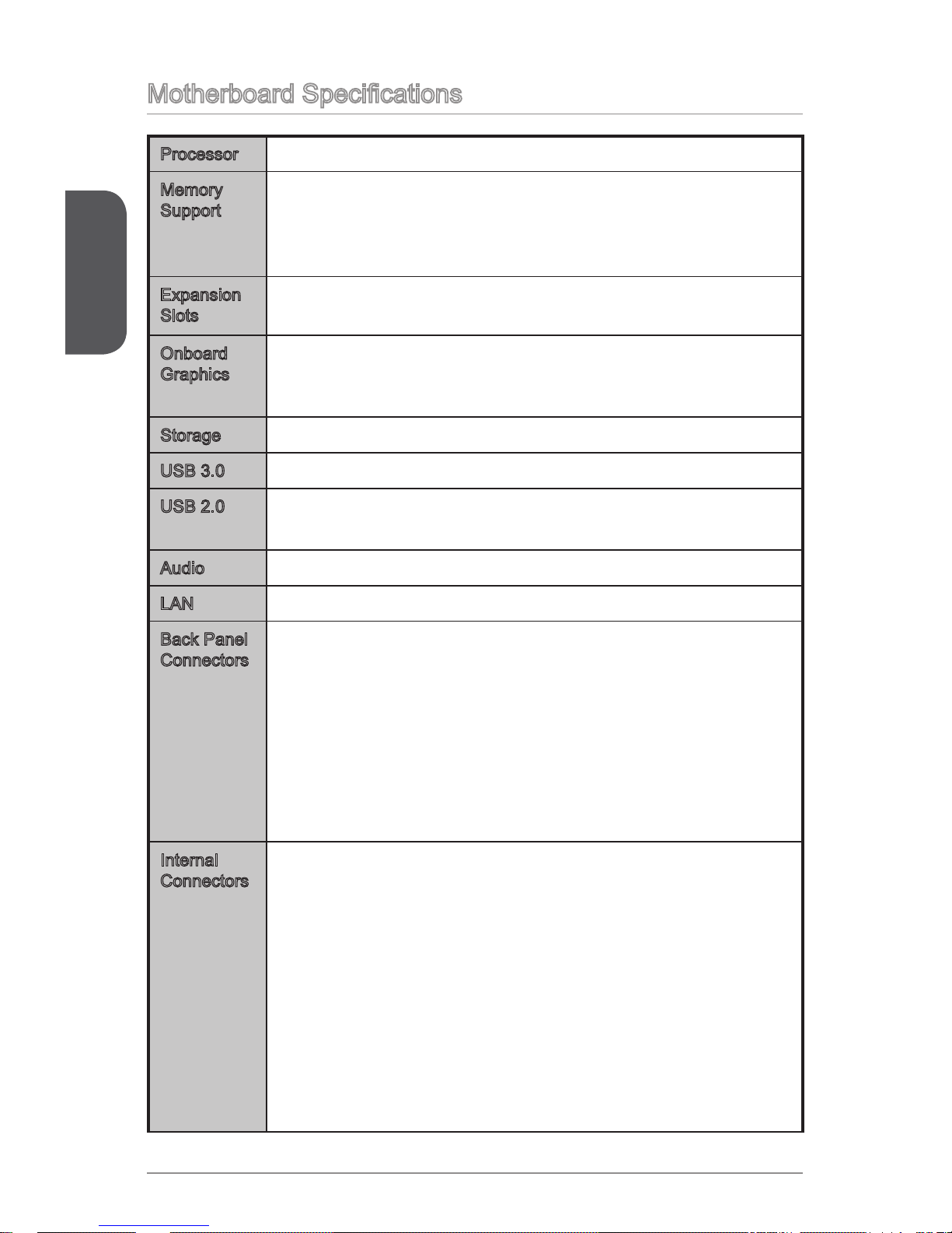
Motherboard Specications
Processor AMD Socket AM1 Processors■
Memory
Support
2x DDR3 memory slots supporting up to 32GB
Supports DDR3 1600/ 1333/ 1066 MHz
Single channel memory architecture
Supports non-ECC, un-buered memory
■
■
■
■
Expansion
Slots
1x PCIe 2.0 x16 slot, supports x4 speed
1x Mini-PCIe slot
■
■
Onboard
Graphics
1x VGA port, supporting a maximum resolution of 1920x1200
1x HDMI port, supporting a maximum resolution of 4096x2160
1x DVI-D port, supporting a maximum resolution of 1920x1200
■
■
■
Storage 2x SATA 6Gb/s ports■
USB 3.0 2x USB 3.0 ports on the back panel■
USB 2.0 6x USB 2.0 ports (2 ports on the back panel, 4 ports available
through the internal USB connectors)
■
Audio Realtek® ALC887 Codec■
LAN Realtek® RTL8111G Gigabit LAN controller■
Back Panel
Connectors
1x PS/2 keyboard port
1x PS/2 mouse port
1x VGA port
1x DVI-D port
1x HDMI port
2x USB 3.0 ports
2x USB 2.0 ports
1x LAN (RJ45) port
3x audio jacks
■
■
■
■
■
■
■
■
■
Internal
Connectors
1x 24-pin ATX main power connector
1x 4-pin ATX 12V power connector
2x SATA 6Gb/s connectors
2x USB 2.0 connectors (supports additional 4 USB 2.0 ports)
1x 3-pin CPU fan connector
1x 4-pin system fan connector
1x Front panel audio connector
1x Serial port connector
1x TPM connector
1x System panel connector
1x Chassis Intrusion connector
1x Clear CMOS jumper
■
■
■
■
■
■
■
■
■
■
■
■
English
13
BIOS
Features
UEFI AMI BIOS
ACPI 5.0, PnP 1.0a, SM BIOS 2.7, DMI 2.0
Multi-language
■
■
■
Form Factor Mini-ITX Form Factor
6.7 in. x 6.7 in. (17.0 cm x 17.0 cm)
■
■
For the latest information about CPU, please visit
http://www.msi.com/service/cpu-support/
For more information on compatible components, please
visit http://www.msi.com/service/test-report/
English
14
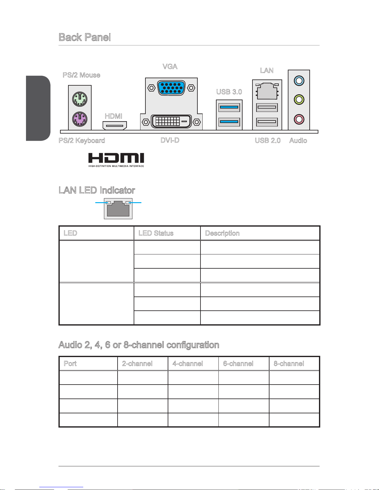
Back Panel
LAN LED Indicator
LINK/ACT
LED
SPEED
LED
LED LED Status Description
Link/ Activity LED
O No link
Yellow Linked
Blinking Data activity
Speed LED
O 10 Mbps connection
Green 100 Mbps connection
Orange 1 Gbps connection
Audio 2, 4, 6 or 8-channel conguration
Port 2-channel 4-channel 6-channel 8-channel
Blue Line in RS-Out RS-Out RS-Out
Green Line out FS-Out FS-Out FS-Out
Pink Mic Mic CS-Out CS-Out
Front audio - - - SS-Out
PS/2 Mouse
PS/2 Keyboard USB 2.0
USB 3.0
VGA
LAN
Audio
DVI-D
HDMI
®
English
15
APU & Heatsink Installation
When installing an APU, always remember to install an APU heatsink. An APU
heatsink is necessary to prevent overheating and maintain system stability. Follow
the steps below to ensure correct APU and heatsink installation. Wrong installation
can damage both the APU and the motherboard.
Video Demonstration
Watch the video to learn how to install APU & heatsink at the address
below.
http://youtu.be/s--YUBNkHc8
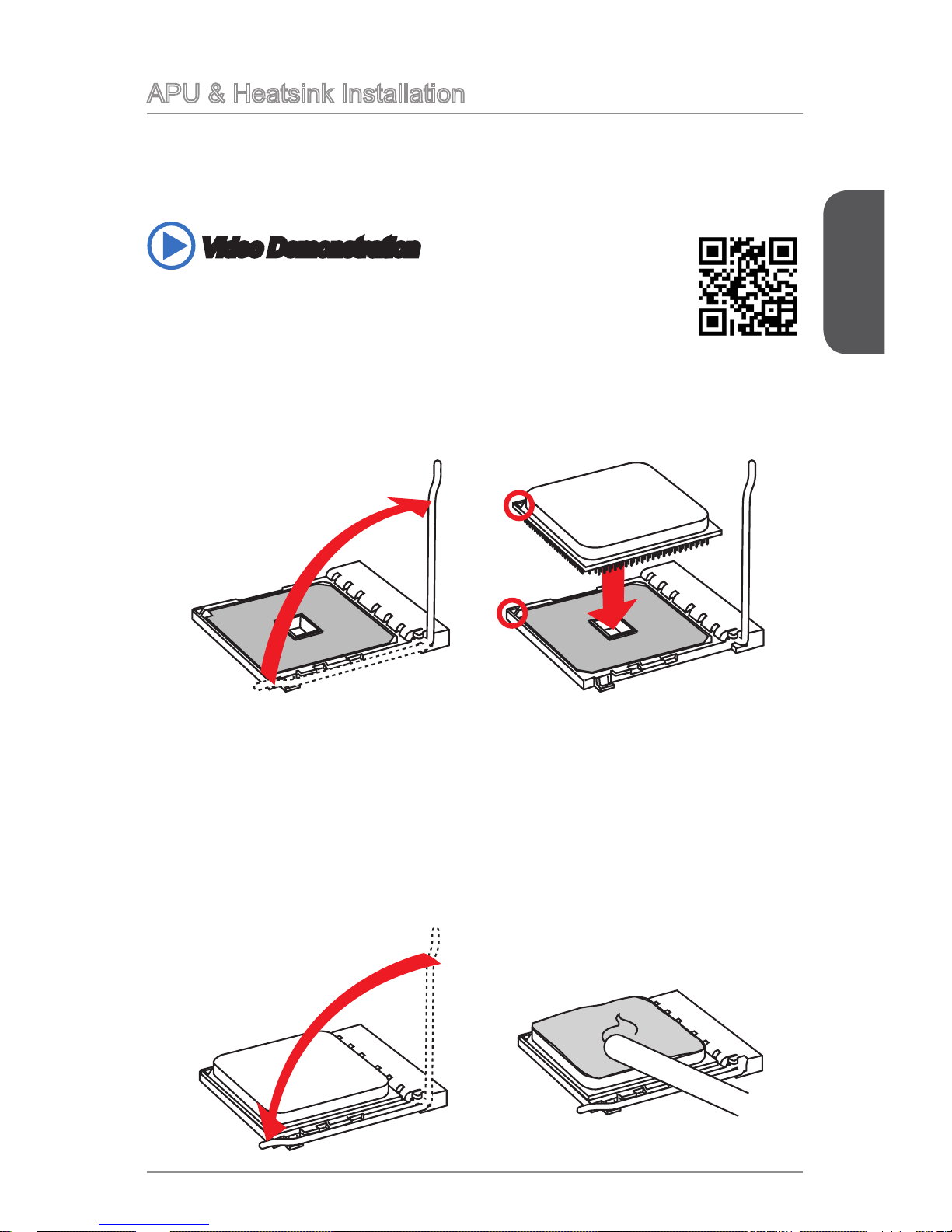
3. If the APU is correctly installed, the pins should be completely embedded into
the socket and can not be seen. Please note that any violation of the correct
installation procedures may cause permanent damages to your motherboard.
4. Press the APU down rmly into the socket and close the lever. As the APU is
likely to move while the lever is being closed, always close the lever with your
ngers pressing tightly on top of the APU to make sure the APU is properly and
completely embedded into the socket.
5. Evenly spread a thin layer of thermal paste (or thermal tape) on the top of the
APU. This will help in heat dissipation and prevent APU overheating.
1. Pull the lever sideways away from the socket. Make sure to raise the lever up to
a 90-degree angle.
2. Look for the gold arrow of the APU. The gold arrow should point as shown in the
picture. The APU can only t in the correct orientation.
English
16
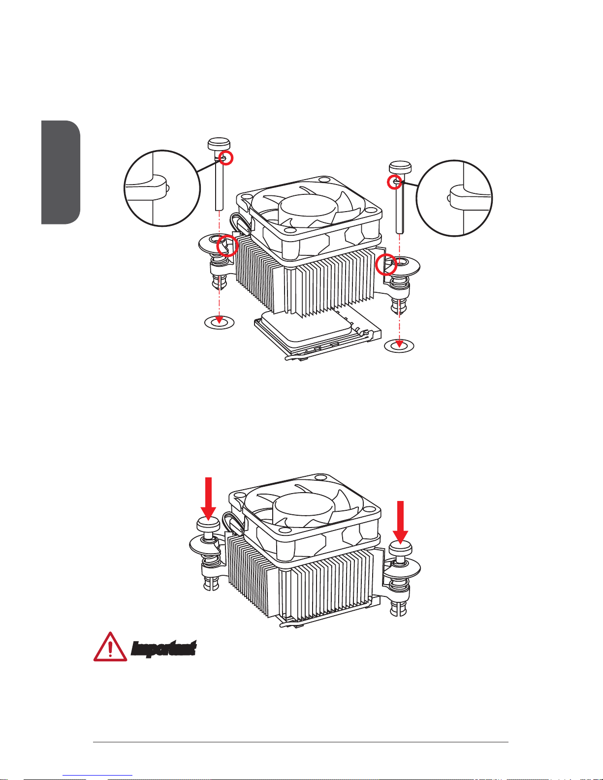
6. Locate the CPUFAN connector on the motherboard.
7. Place the heatsink on the motherboard with the fan’s cable facing towards the
fan connector and the fasteners matching the holes on the motherboard.
8. Align the protrusion of the push-pin with the notch of the fastener as shown in
the picture. Insert the two push-pins into the two fasteners.
Important
Conrm that the APU cooler has formed a tight seal with the APU before booting
your system.
Please refer to the documentation in the APU cooler package for more details
about APU cooler installation.
•
•
9. Push down the push-pins until the two fasteners get wedged into the holes on
the motherboard. Press the two fasteners down to fasten the heatsink. As each
fastener locks into position a click should be heard.
10. Inspect the motherboard to ensure that the fastener-ends have been properly
locked in place.
11. Attach the fan cable to the CPUFAN connector on the motherboard.
 Loading...