

Page 1
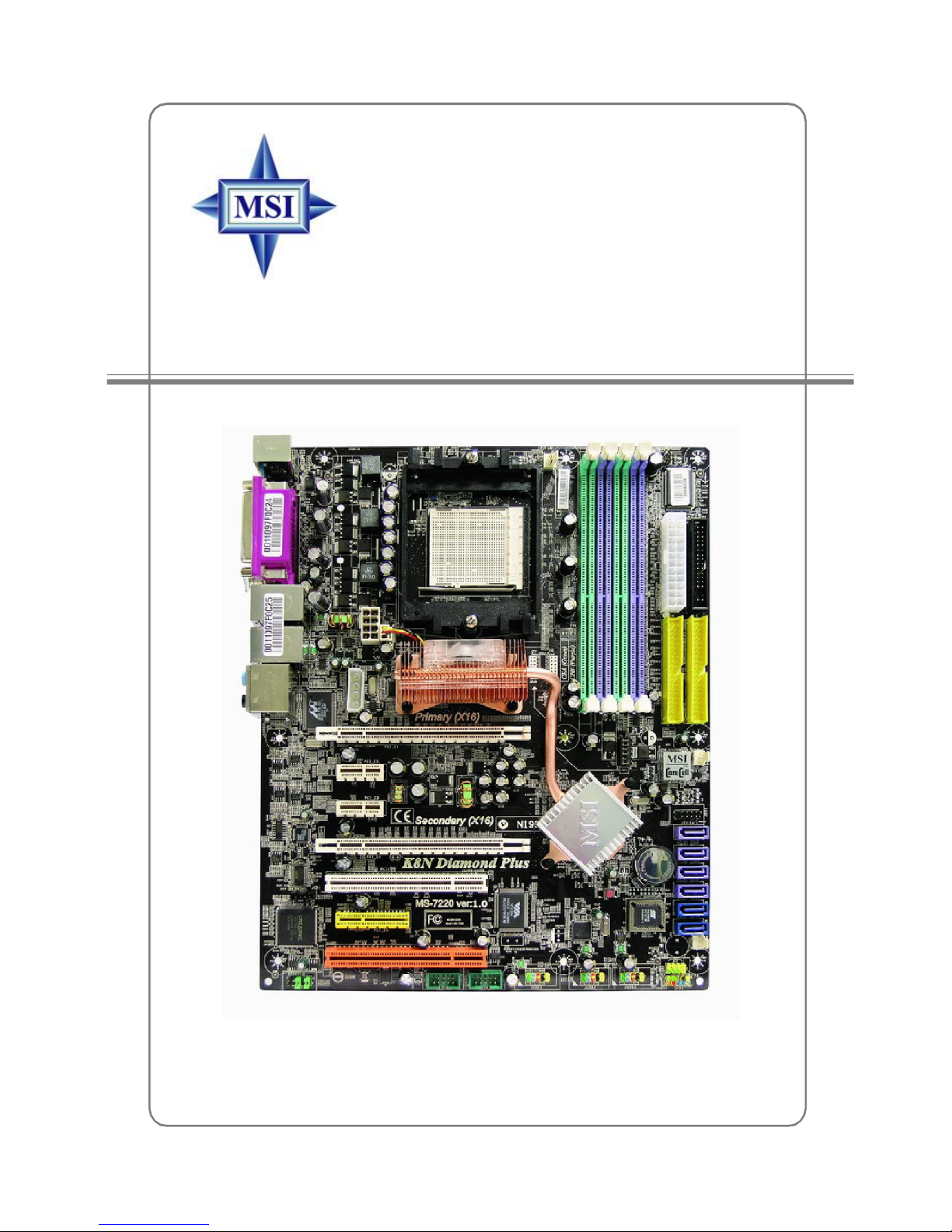
K8N Diamond Plus Series
MS-7220 (v1.X) ATX Mainboard
G52-M7220X3
i
Page 2
FCC-B Radio Frequency Interference Statement
This equipment has been tested
and found to comply with the
limits for a class B digital device,
pursuant to part 15 of the FCC
rules. These limits are designed
to provide reasonable protection against harmful interference in a residential installation.
This equipment generates, uses and can radiate radio frequency energy and, if not
installed and used in accordance with the instruction manual, may cause harmful
interference to radio communications. However, there is no guarantee that interference
will not occur in a particular installation. If this equipment does cause harmful
interference to radio or television reception, which can be determined by turning the
equipment off and on, the user is encouraged to try to correct the interference by one
or more of the measures listed below.
=Reorient or relocate the receiving antenna.
=Increase the separation between the equipment and receiver.
=Connect the equipment into an outlet on a circuit different from that to which the
receiver is connected.
=Consult the dealer or an experienced radio/television technician for help.
Notice 1
The changes or modifications not expressly approved by the party responsible for
compliance could void the user’s authority to operate the equipment.
Notice 2
Shielded interface cables and A.C. power cord, if any, must be used in order to
comply with the emission limits.
VOIR LA NOTICE D’INSTALLATION AVANT DE RACCORDER AU RESEAU.
Micro-Star International
MS-7220
This device complies with Part 15 of the FCC Rules. Operation is subject to the
following two conditions:
(1) this device may not cause harmful interference, and
(2) this device must accept any interference received, including interference that
may cause undesired operation
ii
Page 3

Copyright Notice
The material in this document is the intellectual property of MICRO-STAR
INTERNATIONAL. We take every care in the preparation of this document, but no
guarantee is given as to the correctness of its contents. Our products are under
continual improvement and we reserve the right to make changes without notice.
Trademarks
All trademarks are the properties of their respective owners.
AMD, Athlon™ 64 and Athlon™ FX are registered trademarks of AMD Corporation.
Intel® and Pentium® are registered trademarks of Intel Corporation.
PS/2 and OS®/2 are registered trademarks of International Business Machines
Corporation.
Microsoft is a registered trademark of Microsoft Corporation. Windows® 98/2000/NT/
XP are registered trademarks of Microsoft Corporation.
NVIDIA, the NVIDIA logo, DualNet, and nForce are registered trademarks or trademarks of NVIDIA Corporation in the United States and/or other countries.
Netware® is a registered trademark of Novell, Inc.
Award® is a registered trademark of Phoenix Technologies Ltd.
AMI® is a registered trademark of American Megatrends Inc.
Kensington and MicroSaver are registered trademarks of the Kensington Technology
Group.
PCMCIA and CardBus are registered trademarks of the Personal Computer Memory
Card International Association.
Revision History
Revision Revision History Date
V1.0 First release for PCB 1.X December 2005
with nVIDIA C51D & nForce 4 SLI
V1.1 First release for PCB 1.X (for EU) December 2005
with nVIDIA C51D & nForce 4 SLI
iii
Page 4
Technical Support
If a problem arises with your system and no solution can be obtained from the user’s
manual, please contact your place of purchase or local distributor. Alternatively,
please try the following help resources for further guidance.
† Visit the MSI homepage & FAQ site for technical guide, BIOS updates, driver
updates, and other information: http://www.msi.com.tw & http://www.msi.
com.tw/program/service/faq/faq/esc_faq_list.php
† Contact our technical staff at: support@msi.com.tw
Safety Instructions
1. Always read the safety instructions carefully.
2. Keep this User’s Manual for future reference.
3. Keep this equipment away from humidity.
4. Lay this equipment on a reliable flat surface before setting it up.
5. The openings on the enclosure are for air convection hence protects the equipment from overheating. Do not cover the openings.
6. Make sure the voltage of the power source and adjust properly 110/220V before connecting the equipment to the power inlet.
7. Place the power cord such a way that people can not step on it. Do not place
anything over the power cord.
8. Always Unplug the Power Cord before inserting any add-on card or module.
9. All cautions and warnings on the equipment should be noted.
10. Never pour any liquid into the opening that could damage or cause electrical
shock.
11. If any of the following situations arises, get the equipment checked by a service
personnel:
† The power cord or plug is damaged.
† Liquid has penetrated into the equipment.
† The equipment has been exposed to moisture.
† The equipment has not work well or you can not get it work according to
User’s Manual.
† The equipment has dropped and damaged.
† The equipment has obvious sign of breakage.
12. Do not leave this equipment in an environment unconditioned, storage
temperature above 600 C (1400F), it may damage the equipment.
CAUTION: Danger of explosion if battery is incorrectly replaced.
Replace only with the same or equivalent type recommended by the
manufacturer.
iv
Page 5

WEEE Statement
v
Page 6
vi
Page 7
vii
Page 8

CONTENTS
FCC-B Radio Frequency Interference Statement......................................................ii
Copyright Notice.......................................................................................................iii
Revision History.......................................................................................................iii
Technical Support....................................................................................................iv
Safety Instructions..................................................................................................iv
WEEE Statement...........................................................................................................v
English..............................................................................................................E-1-1
Getting Started.............................................................................................E-1-3
Hardware Setup...........................................................................................E-2-1
BIOS Setup...................................................................................................E-3-1
Français...............................................................................................................F-1
Manuel d’utilisation...........................................................................................F-3
Deutsch...............................................................................................................G-1
Benutzerhandbuch.........................................................................................G-3
viii
Page 9

Getting Started
K8N Diamond Plus
Series User’s Manual
English
E1-1
Page 10

MS-7220 ATX Mainboard
E1-2
Page 11

Getting Started
Chapter 1. Getting
Started
Getting Started
Thank you for choosing the K8N Diamond Plus (MS-7220)
Series v1.X ATX mainboard. The K8N Diamond Plus mainboard is
based on nVIDIA® C51D & nForce™4 SLI chipsets for optimal system efficiency. Designed to fit the advanced AMD® K8 Athlon 64 FX
/ Athlon 64X2/ Athlon 64 processor, the K8N Diamond Plus Series mainboard delivers a high performance and professional desktop platform solution.
E1-3
Page 12

MS-7220 ATX Mainboard
Mainboard Specifications
CPU
† Supports Socket-939 for AMD K8 Athlon 64 FX / Athlon 64X2/ Athlon 64 processor
† Supports up to 4000+ Athlon FX55 , or higher CPU
(For the latest information about CPU, please visit http://www.msi.com.tw/program/
products/mainboard/mbd/pro_mbd_cpu_support.php)
Chipset
† nVIDIA C51D Chipset
- HyperTransport link to the AMD Athlon 64 FX / Athlon 64X2/ Athlon 64 CPU
- HyperTransport supporting speed up to 1GHz (2000MT/s)
- Supports 1 PCI Express x16 interface
† nVIDIA nForce4 SLI Chipset
- Supports 1 PCI Express x16/ 2 PCI Express x1/ 1 PCI Express x2 connection
- Two independent SATA controllers, for four drives
- Dual Fast ATA-133 IDE controllers
- IEEE802.3 nVIDIA MAC for 1000BASE-T
Main Memory
† Supports dual channel, eight memory banks DDR 266/333/400, using four 184-
pin DDR DIMMs
† Supports a maximum memory size up to 4GB
† Supports 2.6v DDR SDRAM DIMM
(For the updated supporting memory modules, please visit http://www.msi.com.tw/
program/products/mainboard/mbd/pro_mbd_trp_list.php.)
Slots
† Supports 2 PCI Express x16 slots (supports PCI Express Bus specification v1.
0a compliant)
† Supports 2 PCI Express x1 slots (supports PCI Express Bus specification v1.0a
compliant)
† Supports 1 PCI Express x4 slot interface supports PCI Express x2 transfer rate
(supports PCI Express Bus specification v1.0a compliant)
† Two 32-bit 3.3V/5V Master PCI Bus slots, includes one orange slot which
supports 2 master for MSI special PCI function card (ex. wireless LAN and
bluetooth combo card.).
On-Board IDE
† An IDE controller on the nVIDIA® nForce4 SLI chipset provides IDE HDD/CD-ROM
with PIO, Bus Master and Ultra DMA 66/100/133 operation modes
† Can connect up to 4 IDE devices
E1-4
Page 13

Getting Started
On-Board SATA
† nForce 4 SLI supports 4 SATA-II ports (SATA1-4). Transfer speed is up to 3 Gb/
s. Supports RAID 0/ 1/ 0+1/ RAID 5 or JBOD mode.
† Silicon Image’s SATARAID supports another 2 SATA-II ports (SATA5/6).
Transfer rate is up to 3 Gb/s. Supports RAID 0 & 1 mode. (optional)
USB Interface
† 10 USB ports
- Controlled by nForce4 SLI chipset
- 4 ports in the rear I/O, 6 ports via the external bracket
NV RAID (software)
† RAID 0, 1, 0+1, 5 or JBOD is supported
† Support up to 4 SATA devices
Silicon Image’s SATARAID (Software) (Optional)
† RAID 0 or 1 and multiple RAID groups are supported
† Support up to 2 SATA devices connected to a single controller
Dual LAN
† Supports dual LAN jacks
- PCI LAN supports 10/100/1000 Fast Ethernet by Marvell 88E1115 PHY.
- PCIE LAN supports 10/100/1000 Fast Ethernet by Marvell 88E8053.
IEEE 1394 (optional)
† Supports up to three 1394 ports (rear panel x 1, pinheader x 2). Transfer rate
is up to 400Mbps
Audio
† Power by Creative Sound Blaster Audigy H/W audio
-24-bit / 96 KHz audio quality
-Up to 100 db SNR clarity
-7.1 Channel output supported
-Supports S/PDIF digital interface
-PCI 2.3 Specification compliant
On-Board Peripherals
† On-Board Peripherals include:
-1 floppy port supports 1 FDD with 360K, 720K, 1.2M, 1.44M and 2.88Mbytes
-1 serial port (COM1)
-1 parallel port supporting SPP/EPP/ECP mode
-1 Audio jack(5-in-1), coaxial/optical SPDIF out
-1 D-BracketTM 2 pinheader
E1-5
Page 14

MS-7220 ATX Mainboard
-1 CD-In pinheader
-3 IEEE 1394 (Rear * 1 / Front * 2) (optional)
-10 USB1.1/2.0 ports (Rear * 4 / Front * 6)
-1 IrDA pinheader
BIOS
† The mainboard BIOS provides “Plug & Play” BIOS which detects the peripheral
devices and expansion cards of the board automatically.
† The mainboard provides a Desktop Management Interface (DMI) function which
records your mainboard specifications.
† Supports boot from LAN, USB Device 1.1 & 2.0, and SATA HDD.
Dimension
† ATX Form Factor (30.4 cm X 24.4 cm)
Mounting
† 9 mounting holes
MSI Reminds You...
To create a bootable RAID volume for a Windows 2000 environment,
Microsoft’s Windows 2000 Service Pack 4 (SP4) is required. As the
end user cannot boot without SP4, a combination installation CD must
be created before attempting to install the operating system onto the
bootable RAID volume.
To create the combination installation CD, please refer to the following website:
http://www.microsoft.com/windows2000/downloads/servicepacks/
sp4/HFdeploy.htm
E1-6
Page 15
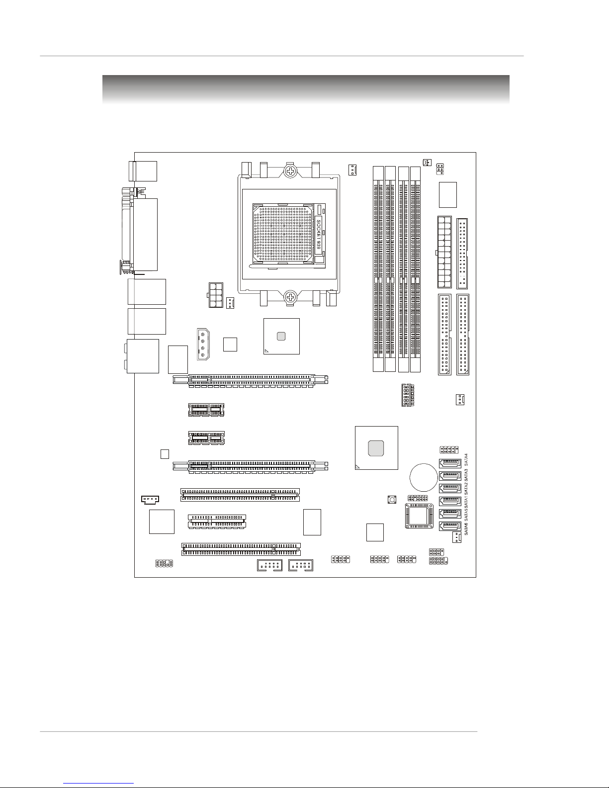
Mainboard Layout
DIMM 1DIMM 3DIMM 2DIMM 4FDD1Winbond W83627EHFJPWR1IDE 2IDE
1
JCI1
CPUFAN1
JDB1
JLPC1
JCD1
SYSFAN1
PWRFAN1
CA0106-DAT
nvidia
nvidia
nForce4 SLI
(Optional)
Getting Started
Top : mouse
Bottom: keyboard
Top : Parallel Port
Bottom:
COM Port
1394 Port (optional)
SPDIF OUT
(coaxial)
T: LAN jack
B: USB ports
T: LAN jack
B: USB ports
T:
Line-In
M:
Line-Out
B:
Mic
T:RS-Out
M:CS
B:SPDIF Out
(optical)
-Out
88E1115
JPWR2
JPWR3
PCI _E2
NBFAN1
88E8053
PCI _E1
JIR1
C51D
JV1
PCI _E3
CREATIVE
JAUD1
PCI _E4
PCI 1
PCI _E5
PCI 2
(Optional)
VIA
VT6306
(Optional)Silicon
(Optional)
J1394_2J1394_1
JUSB1 JUSB2 JUSB3
Image
RAID
SW1
+
BATT
BIOS
JFP2
JFP1
(Optional)
K8N Diamond Plus (MS-7220 v1.X) Series ATX Mainboard
E1-7
Page 16
MS-7220 ATX Mainboard
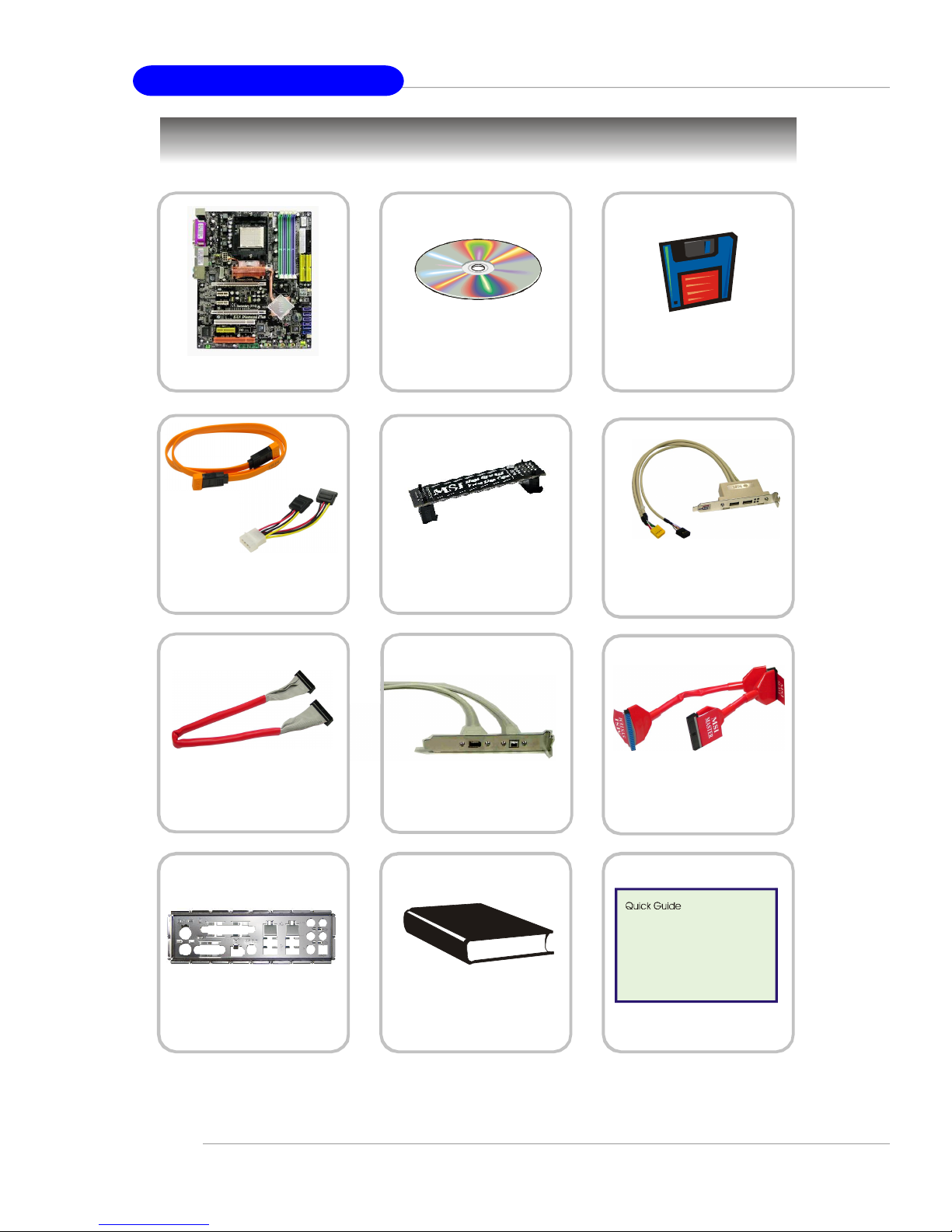
Packing Contents
MSI motherboard
SATA Cable/
Power Cable (Optional)
Round Cable of
Floppy Disk
MSI Driver/ Creative
Audio Driver/ Utility CD
SLI Video Link Card
1394 Cable
(Optional)
SATA RAID Driver
Diskette
D-Bracket 2
(Optional)
Round Cable of
IDE Devices
Back IO Shield
* The pictures are for reference only and may vary from the packing contents of
the product you purchased.
E1-8
User’s Guide/
Test Report
Quick Guide
Page 17

Hardware Setup
Chapter 2. Hardware Setup
Hardware Setup
This chapter tells you how to install the CPU, memory modules,
and expansion cards, as well as how to setup the jumpers on the
mainboard. Also, it provides the instructions on connecting the peripheral devices, such as the mouse, keyboard, etc.
While doing the installation, be careful in holding the components and follow the installation procedures.
E2-1
Page 18
MS-7220 ATX Mainboard
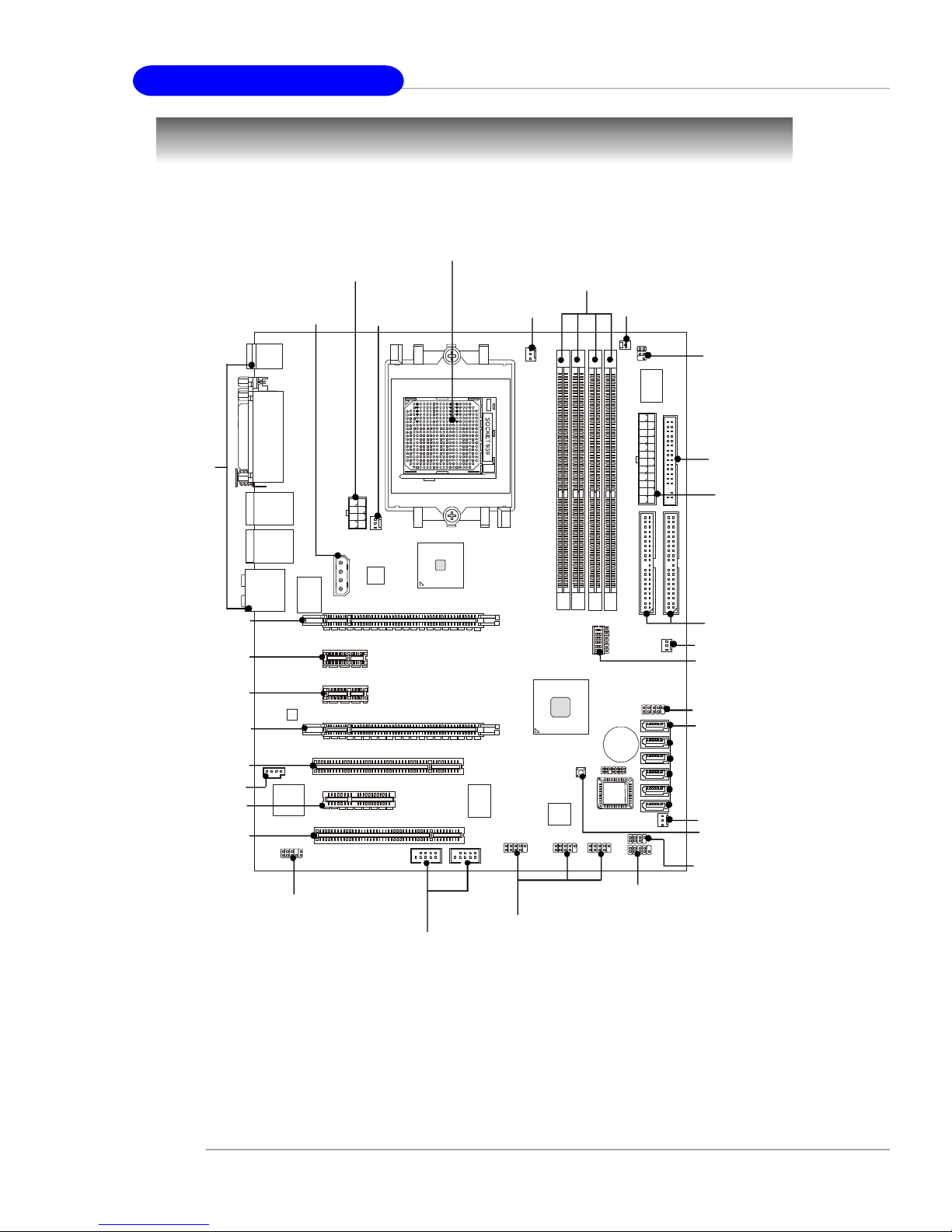
Quick Components Guide
JPWR2, p.2-9
JPWR3, p.2-9
S_FAN1,
p.2-15
CPU, p.2-3
CPUFAN1,
p.2-15
DDR DIMMs, p.2-6
JCI1, p.2-20
JIR1, p.2-18
Back Panel
I/O, p.2-11
PCI_E1, p.2-25
PCI_E2, p.2-25
PCI_E3, p.2-25
PCI_E4, p.2-25
PCI1, p.2-28
JCD1, p.2-20
PCI_E5, p.2-25
PCI2, p.2-28
JAUD1, p.2-19
FDD1, p.2-15
JPWR1,
p.2-9
IDE1/2, p.2-16
PWRFAN1, p.2-15
JV1, p.2-24
JDB1, p.2-21
SATA1~6,
p.2-17
SYSFAN1, p.2-15
SW1, p.2-24
JFP2, p.2-18
JFP1, p.2-18
JUSB1~3, p.2-18
J1394_1~2,
p.2-20
E2-2
Page 19

Hardware Setup
Central Processing Unit: CPU
The mainboard supports AMD® Athlon64 X2/ Athlon64 FX/ Athlon64 processors.
The mainboard uses a CPU socket called Socket-939 for easy CPU installation. When
you are installing the CPU, make sure the CPU has a heat sink and a cooling fan
attached on the top to prevent overheating. If you do not have the heat sink and
cooling fan, contact your dealer to purchase and install them before turning on the
computer.
For the latest information about CPU, please visit http://www.msi.com.tw/program/products/mainboard/mbd/pro_mbd_cpu_support.php.
MSI Reminds You...
Overheating
Overheating will seriously damage the CPU and system, always make
sure the cooling fan can work properly to protect the CPU from
overheating.
Replacing the CPU
While replacing the CPU, always turn off the ATX power supply or
unplug the power supply’s power cord from grounded outlet first to
ensure the safety of CPU.
Overclocking
This motherboard is designed to support overclocking. However, please
make sure your components are able to tolerate such abnormal setting,
while doing overclocking. Any attempt to operate beyond product specifications is not recommended. We do not guarantee the damages
or risks caused by inadequate operation or beyond product
specifications.
E2-3
Page 20

MS-7220 ATX Mainboard
Gold arrow
Gold arrow
Gold arrow
Correct CPU placement
O
CPU Installation Procedures for Socket 939
1.Please turn off the power and
unplug the power cord before
installing the CPU.
Open Lever
2.Pull the lever sideways away
from the socket. Make sure to
raise the lever up to a 90-degree angle.
3.Look for the gold arrow of the
CPU. The gold arrow should
point as shown in the picture.
The CPU can only fit in the correct orientation.
4.If the CPU is correctly installed,
the pins should be completely
embedded into the socket and
can not be seen. Please note
that any violation of the correct
installation procedures may
cause permanent damages to
your mainboard.
Sliding
Plate
90 degree
5. Press the CPU down firmly into
the socket and close the lever.
As the CPU is likely to move while
the lever is being closed, always close the lever with your
fingers pressing tightly on top of
the CPU to make sure the CPU is
properly and completely embedded into the socket.
E2-4
Page 21
Hardware Setup
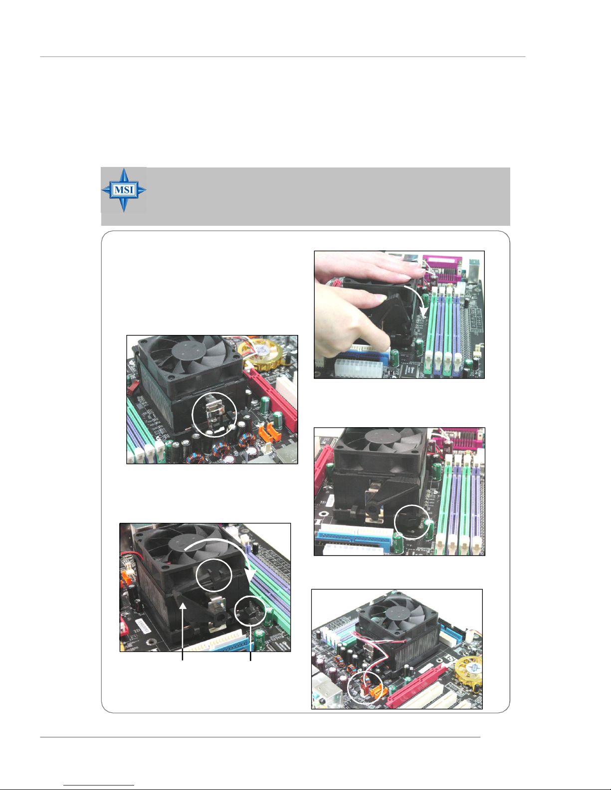
Installing AMD Socket 939 CPU Cooler Set
When you are installing the CPU, make sure the CPU has a heat sink and
a cooling fan attached on the top to prevent overheating. If you do not have
the heat sink and cooling fan, contact your dealer to purchase and install them before
turning on the computer.
MSI Reminds You...
Mainboard photos shown in this section are for demonstration of the
cooler installation for Socket 939 CPUs only. The appearance of
your mainboard may vary depending on the model you purchase.
1.Position the cooling set onto the retention mechanism.
Hook one end of the clip to hook
first, and then press down the other
end of the clip to fasten the cooling
set on the top of the retention
mechanism.
2.Locate the Fix Lever, Safety Hook
and the Fixed Bolt.
Lift up the intensive fixed lever.
3.Fasten down the lever.
4.Make sure the safety hook completely
clasps the fixed bolt of the retention
mechanism.
Safety Hook
Fixed Lever
5.Attach the CPU Fan cable to the CPU
fan connector on the mainboard.
Fixed Bolt
E2-5
Page 22
MS-7220 ATX Mainboard
Memory
The mainboard provides 4 slots for 184-pin DDR SDRAM DIMM (Double In-Line
Memory Module) modules and supports the memory size up to 4GB. You can install
DDR266/333/400 modules on the DDR DIMM slots (DIMM1~4).
For the updated supporting memory modules, please visit http://www.msi.com.tw/
program/products/mainboard/mbd/pro_mbd_trp_list.php.
DIMM1~4
(from left to right)
Channel A (DIMM1 & DIMM3): Green
Channel B (DIMM2 & DIMM4): Purple
Introduction to DDR SDRAM
DDR (Double Data Rate) SDRAM is similar to conventional SDRAM, but doubles
the rate by transferring data twice per cycle. It uses 2.5 volts as opposed to 3.3 volts
used in SDR SDRAM, and requires 184-pin DIMM modules rather than 168-pin DIMM
modules used by SDR SDRAM. High memory bandwidth makes DDR an ideal solution
for high performance PC, workstations and servers.
DIMM Module Combination
Install at least one DIMM module on the slots. Each DIMM slot supports up to a
maximum size of 1GB. Users can install either single- or double-sided modules to
meet their own needs. Please note that each DIMM can work respectively for
single-channel DDR, but there are some rules while using dual-channel
DDR (Please refer to the suggested DDR population table below). Users may install
memory modules of different type and density on different-channel DDR DIMMs.
However, the same type and density memory modules are necessary while
using dual-channel DDR, or instability may happen. Please refer to the following table
for detailed dual-channel DDR. Other combination not listed below will function as
single-channel DDR.
E2-6
Page 23
Hardware Setup
GREEN
DIMM1 (Ch A) DIMM2 (Ch B) DIMM3 (Ch A) DIMM4 (Ch B) System Density
128MB~1GB 128MB~1GB 256MB~2GB
128MB~1GB 128MB~1GB 128MB~1GB 128MB~1GB 512MB~4GB
MSI Reminds You...
-Dual-channel DDR works ONLY in the 3 combinations listed in
the table shown in the previous page.
-Please select the identical memory modules to install on the dual
channel, and DO NOT install three memory modules on three
DIMMs, or it may cause some failure.
-Always insert the memory modules into the GREEN slots first, and
it is strongly recommended not to insert the memory modules into
the PURPLE slots while the GREEN slots are left empty.
- Due to the South Bridge resource deployment, the system density
will only be detected up to 3+GB (not full 4GB) when each DIMM is
installed with an 1GB memory module.
PURPLE
GREEN
128MB~1GB 128MB~1GB 256MB~2GB
PURPLE
Recommended Memory Combination List
DIMM Slots
Green Green
DIMM1
S
D
S -
D -
S
Purple
DIMM2 DIMM3 DIMM4
- -
-
-
-
S
-
D-
S D -
S
-
- - S S
D D
- S
D
S: Single Side D: Double Side
S
D
- D D
S
D
Purple
-
-
-
-
-
S
D
Max Speed
DDR 400
DDR 400
DDR 400
DDR 400
DDR 400
DDR 333
DDR 400
DDR 333
DDR 400
DDR 400
DDR 400
DDR 333
E2-7
Page 24
MS-7220 ATX Mainboard
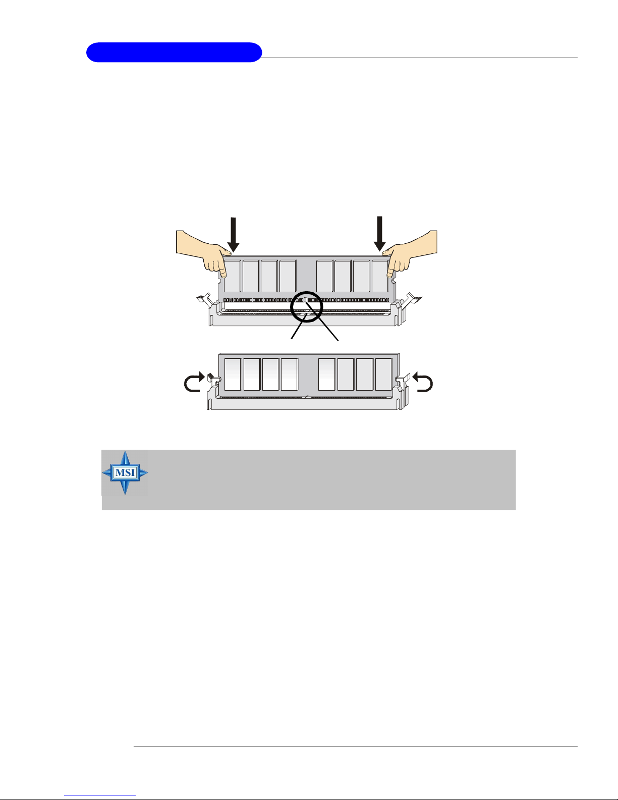
Installing DDR Modules
1. The DDR DIMM has only one notch on the center of module. The module will only
fit in the right orientation.
2. Insert the DIMM memory module vertically into the DIMM slot. Then push it in until
the golden finger on the memory module is deeply inserted in the socket.
3. The plastic clip at each side of the DIMM slot will automatically close.
Volt
MSI Reminds You...
You can barely see the golden finger if the module is properly inserted in the socket.
Notch
E2-8
Page 25
Hardware Setup
Power Supply
The mainboard supports ATX power supply for the power system. Before
inserting the power supply connector, always make sure that all components are
installed properly to ensure that no damage will be caused.
ATX 24-Pin Power Connector: JPWR1
This connector allows you to connect an SSI power supply. To connect the
SSI power supply, make sure the plug of the power supply is inserted in the proper
orientation and the pins are aligned. Then push down the power supply firmly into
the connector.
Pin Definition
PIN SIGNAL
13 +3.3V
14 -12V
15 GND
16 PS-ON#
17 GND
18 GND
19 GND
20 NC
21 +5V
22 +5V
23 +5V
24 GND
JPWR1
13
24 12
1
PIN SIGNAL
1 +3.3V
2 +3.3V
3 GND
4 +5V
5 GND
6 +5V
7 GND
8 PWR OK
9 5VSB
10 +12V
11 +12V
12 +3.3V
ATX 12V Power Connector: JPWR2/ JPWR3
The 12V power connector (JPWR2) is used to provide power to the CPU. The
other one 12V power connector(JPWR3) is used to provide power to the installed PCI
Express graphics card.
185
4
JPWR2
JPWR2 Pin Definition
PINSIGNAL
1 GND
2 GND
3 GND
4 GND
PINSIGNAL
5 +12V
6 +12V
7 +12V
8 +12V
1
JPWR3
JPWR3 Pin Definition
PIN SIGNAL
1 5V
2 GND
3 GND
4 12V
MSI Reminds You...
1. These three connectors connect to the ATX power supply and have to
work together to ensure stable operation of the mainboard.
2. Power supply of 450 watts (and above) is highly recommended for
system stability.
3. For ATX 12V power connection, it should be greater than 18A.
E2-9
Page 26
MS-7220 ATX Mainboard
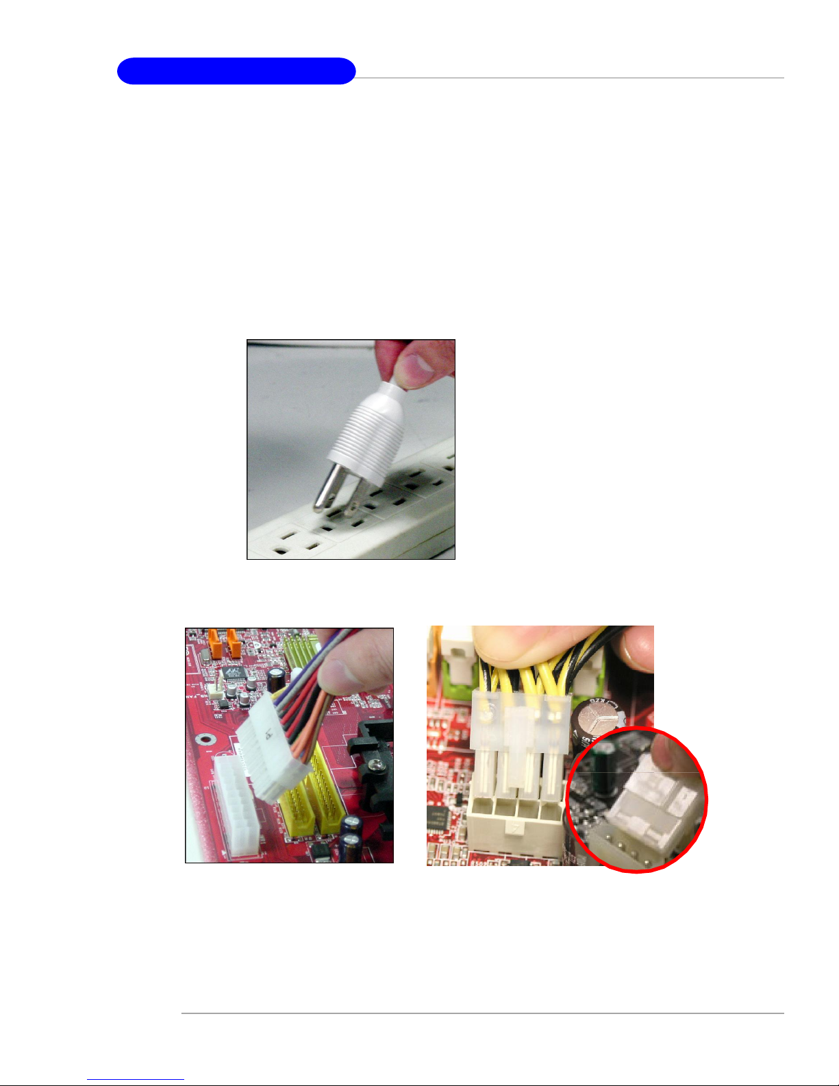
Important Notification about Power Issue
NForce chipset is very sensitive to ESD (Electrostatic Discharge), therefore
this issue mostly happens while the users intensively swap memory modules under
S5 (power-off) states, and the power code is plugged while installing modules. Due
to several pins are very sensitive to ESD, so this kind of memory-replacement actions
might cause system chipset unable to boot. Please follow the following solution to
avoid this situation.
Unplug the AC power cable (shown in figure 1) or unplug the JPWR1/ JPWR2/
JPWR3 power connectors (shown in figure 2 & 3) before the 1st installation or during
system upgrade procedure.
Figure 1:
Unplug the AC power cable
Figure 2:
Unplug the JPWR1 power conn.
E2-10
Figure 3:
Unplug the JPWR2/JPWR3 power
connectors
Page 27
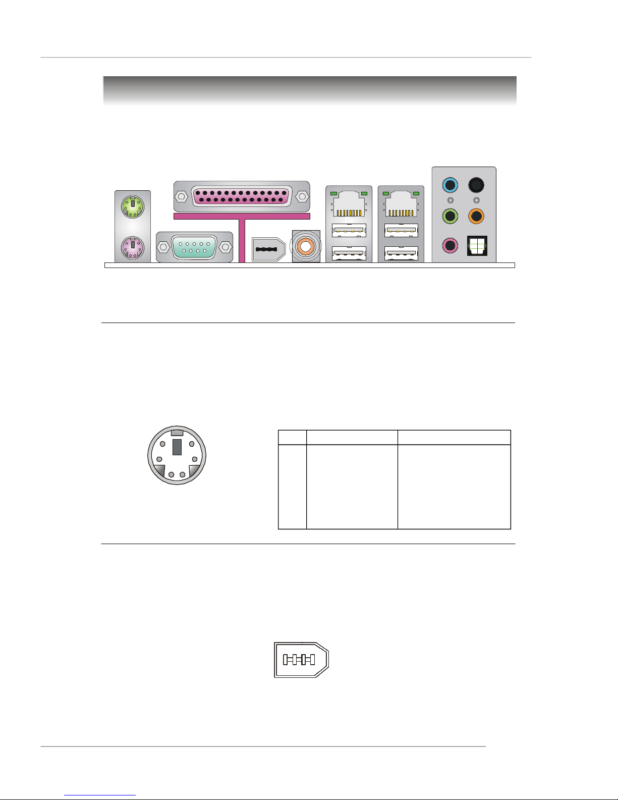
Back Panel
The back panel provides the following connectors:
Hardware Setup
L-In
RS-Out
Parallel
Mouse
Keyboard
COM Port
1394 Port
(Optional)
SPDIF
Out
(Coaxial)
LAN
USB Ports
LAN
L-Out
Mic
CS-Out
SPDIF Out
(Optical)
Mouse Connector (Green) / Keyboard Connector (Purple)
The mainboard provides a standard PS/2® mouse/keyboard mini DIN connector
for attaching a PS/2® mouse/keyboard. You can plug a PS/2® mouse/keyboard directly
into this connector. The connector location and pin assignments are as follows:
Pin Definition
6
4
2
PS/2 Mouse / Keyboard
(6-pin Female)
5
3
1
PIN SIGNAL DESCRIPTION
1 Mouse/Keyboard Data Mouse/Keyboard data
2 NC No connection
3 GND Ground
4 VCC +5V
5 Mouse/Keyboard Clock Mouse/Keyboard clock
6 NC No connection
IEEE1394 Port (Optional)
The back panel provides one standard IEEE 1394 port. The IEEE1394 highspeed serial bus complements USB by providing enhanced PC connectivity for a
wide range of devices, including consumer electronics audio/video (A/V) appliances,
storage peripherals, other PCs, and portable devices.
IEEE1394 Port
E2-11
Page 28
MS-7220 ATX Mainboard
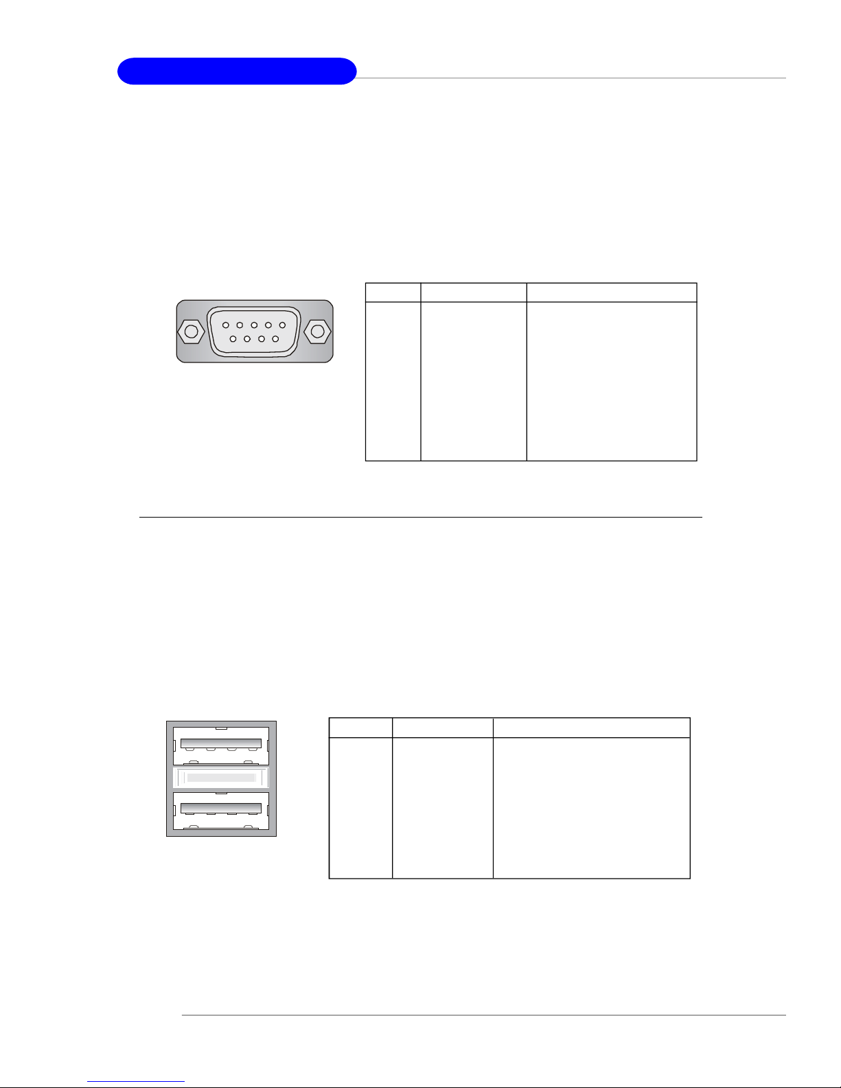
Serial Port Connector
The mainboard offers one 9-pin male DIN connector as the serial port. The port
is a 16550A high speed communication port that sends/receives 16 bytes FIFOs. You
can attach a serial mouse or other serial devices directly to the connector.
Pin Definition
1 2 3 4 5
6 7 8 9
9-Pin Male DIN Connector
PIN SIGNAL DESCRIPTION
1 DCD Data Carry Detect
2 SIN Serial In or Receive Data
3 SOUT Serial Out or Transmit Data
4 DTR Data Terminal Ready)
5 GND Ground
6 DSR Data Set Ready
7 RTS Request To Send
8 CTS Clear To Send
9 RI Ring Indicate
USB Connectors
The mainboard provides two OHCI (Open Host Controller Interface) Universal
Serial Bus roots for attaching USB devices such as keyboard, mouse or other USBcompatible devices. You can plug the USB device directly into the connector.
USB Port Description
PIN SIGNAL DESCRIPTION
1 VCC +5V
1 2 3 4
5 6 7 8
USB Ports
2 -Data 0 Negative Data Channel 0
3 +Data0 Positive Data Channel 0
4 GND Ground
5 VCC +5V
6 -Data 1 Negative Data Channel 1
7 +Data 1 Positive Data Channel 1
8 GND Ground
E2-12
Page 29

Hardware Setup
LAN (RJ-45) Jack
The mainboard provides 2 standard RJ-45 jacks for connection to single Local
Area Network (LAN). This Giga-bit LAN enables data to be transferred at 1000, 100
or 10Mbps. You can connect a network cable to either LAN jack.
Giga-bit LAN Pin Definition
PIN SIGNAL DESCRIPTION
1 D0P Differential Pair 0+
2 D0N Differential Pair 03 D1P Differential Pair 1+
RJ-45 LAN Jack
4 D2P Differential Pair 2+
5 D2N Differential Pair 26 D1N Differential Pair 17 D3P Differential Pair 3+
8 D3N Differential Pair 3-
Audio Port Connectors
The left 3 audio jacks are for 2-channel mode for stereo speaker output: Line
Out is a connector for Speakers or Headphones. Line In is used for external CD
player, Tape player, or other audio devices. Mic is a connector for microphones.
However, there is an advanced audio application provided by Creative CA0106 to
offer support for 7.1-channel audio operation and can turn rear audio connectors
from 2-channel to 4-/5.1-/7.1 channel audio.
S/PDIF Out-Coaxial
Line In
Line Out
MIC
Rear Speaker Out
(in 7.1CH / 6CH/ 4CH)
Center/Subwoofer
Speaker Out
( in 7.1CH / 6CH)
S/PDIF Out-Optical
(in 7.1CH / 6CH)
E2-13
Page 30
MS-7220 ATX Mainboard
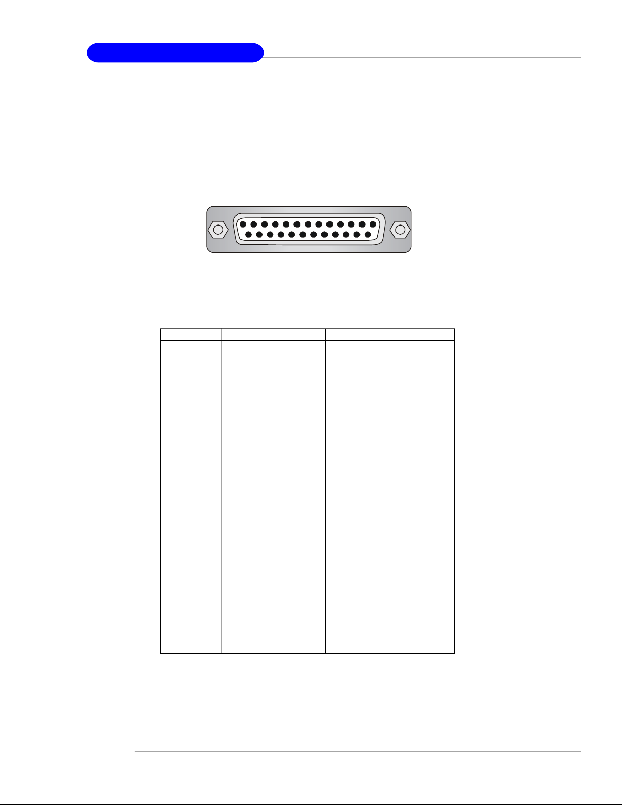
Parallel Port Connector: LPT1
The mainboard provides a 25-pin female centronic connector as LPT. A parallel
port is a standard printer port that supports Enhanced Parallel Port (EPP) and Extended Capabilities Parallel Port (ECP) mode.
13 1
25
14
Pin Definition
PIN SIGNAL DESCRIPTION
1 STROBE Strobe
2 DATA0 Data0
3 DATA1 Data1
4 DATA2 Data2
5 DATA3 Data3
6 DATA4 Data4
7 DATA5 Data5
8 DATA6 Data6
9 DATA7 Data7
10 ACK# Acknowledge
11 BUSY Busy
12 PE Paper End
13 SELECT Select
14 AUTO FEED# Automatic Feed
15 ERR# Error
16 INIT# Initialize Printer
17 SLIN# Select In
18 GND Ground
19 GND Ground
20 GND Ground
21 GND Ground
22 GND Ground
23 GND Ground
24 GND Ground
25 GND Ground
E2-14
Page 31

Connectors
The mainboard provides connectors to connect to FDD, IDE HDD, case, LAN,
USB Ports, IR module and CPU/System FAN.
Floppy Disk Drive Connector: FDD1
The mainboard provides a standard floppy disk drive connector that supports
360K, 720K, 1.2M, 1.44M and 2.88M floppy disk types.
FDD1
Hardware Setup
Fan Power Connectors: CPUFAN1 / SYSFAN1 / PWRFAN1 / NBFAN1
The CPUFAN1 (processor fan), SYSFAN1 (system fan), PWRFAN (power fan
) and NBFAN1 (NorthBridge Chipset fan) support system cooling fan with +12V. It
supports three-pin head connector. When connecting the wire to the connectors,
always take note that the red wire is the positive and should be connected to the
+12V, the black wire is Ground and should be connected to GND. If the mainboard
has a System Hardware Monitor chipset on-board, you must use a specially designed fan with speed sensor to take advantage of the CPU fan control.
Sensor
+12V
GND
Sensor
+12V
GND
CPUFAN1 SYSFAN1
PWRFAN1 NBFAN1
NC
+12V
GND
MSI Reminds You...
1.Always consult the vendors for proper CPU cooling fan.
2.CPUFAN1 supports fan control. You can install Core Center utility that will automatically control the CPU fan speed according to
the actual CPU temperature.
3. Please refer to the recommended CPU fans at AMD® official
website.
Sensor
+12V
GND
E2-15
Page 32

MS-7220 ATX Mainboard
Hard Disk Connectors: IDE1 / IDE2
The mainboard has a 32-bit Enhanced PCI IDE and Ultra DMA 33/66/100/133
controller that provides PIO mode 0~4, Bus Master, and Ultra DMA 33/66/100/133
function. You can connect up to four hard disk drives, CD-ROM, or other devices.
IDE1IDE2
IDE1 (Primary IDE Connector)
The first hard drive should always be connected to IDE1. IDE1 can connect a
Master and a Slave drive. You must configure second hard drive to Slave mode by
setting the jumper accordingly.
IDE2 (Secondary IDE Connector)
IDE2 can also connect a Master and a Slave drive.
MSI Reminds You...
If you install two hard disks on cable, you must configure the second
drive to Slave mode by setting its jumper. Refer to the hard disk
documentation supplied by hard disk vendors for jumper setting
instructions.
E2-16
Page 33

Hardware Setup
Serial ATA/Serial ATA RAID Connectors controlled by
nForce4 SLI: SATA1 / SATA2 / SATA3 / SATA4;
Serial ATA/Serial ATA RAID Connectors controlled by
Silicon Image sil3132: SATA5 / SATA6 (Optional)
The single chip of this mainboard is nForce4 SLI which supports four serial
ATA connectors SATA1~SATA4. Silicon Image’s SATARAID of this mainboard supports another two serial ATA connectors SATA5/ SATA6.
SATA1~SATA6 are high-speed Serial ATA interface ports. Each supports serial
ATA data rates of 3 Gb/s. Both connectors are fully compliant with Serial ATA 1.0
specifications. Each Serial ATA connector can connect to 1 hard disk device. Please
refer to the nVidia RAID Introduction & Silicon Image RAID Introduction for detail
software installation procedure.
7
1
SATA4
SATA3
SATA2
SATA1
SATA1~ SATA6 Pin Definition
PIN SIGNAL PIN SIGNAL
1 GND 2 TXP
3 TXN 4 GND
5 RXN 6 RXP
7 GND
SATA5
SATA6
Serial ATA cable
(optional)
Connect to serial ATA ports
MSI Reminds You...
Please do not fold the serial ATA cable in a 90-degree angle, which will
cause the loss of data during the transmission.
Take out the dust cover and
connect to the hard disk
devices
E2-17
Page 34

MS-7220 ATX Mainboard
Front Panel Connectors: JFP1 / JFP2
The mainboard provides two front panel connectors for electrical connection
to the front panel switches and LEDs. JFP1 is compliant with Intel® Front Panel I/O
Connectivity Design Guide.
JFP1 Pin Definition
PIN SIGNAL DESCRIPTION
1 HD_LED_P Hard disk LED pull-up
2 FP PWR/SLP MSG LED pull-up
3 HD_LED_N Hard disk active LED
4 FP PWR/SLP MSG LED pull-up
10
5 RST_SW_N Reset Switch low reference pull-down to GND
9
6 PWR_SW_P Power Switch high reference pull-up
7 RST_SW_P Reset Switch high reference pull-up
8 PWR_SW_N Power Switch low reference pull-down to GND
9 RSVD_DNU Reserved. Do not use.
JFP1
2
1
Power
LED
HDD
LED
Power
Switch
Reset
Switch
JFP2 Pin Definition
JFP2
2
1
Speaker
Power
LED
PIN SIGNAL PIN SIGNAL
8
7
1 GND 2 SPK3 SLED 4 BUZ+
5 PLED 6 BUZ7 NC 8 SPK+
Front USB Connectors: JUSB1 / JUSB2 / JUSB3
The mainboard provides three standard USB 2.0 pin headers JUSB1 & JUSB2
& JUSB3. USB 2.0 technology increases data transfer rate up to a maximum throughput
of 480Mbps, which is 40 times faster than USB 1.1, and is ideal for connecting highspeed USB interface peripherals such as USB HDD, digital cameras, MP3 players,
printers, modems and the like.
JUSB1 & JUSB2 & JUSB3 Pin Definition
PIN SIGNAL PIN SIGNAL
2
1
10
9
JUSB1, JUSB2, JUSB3
(USB 2.0)
1 VCC 2 VCC
3 USB0- 4 USB15 USB0+ 6 USB1+
7 GND 8 GND
9 Key (no pin) 10 USBOC
Connected to JUSB1, JUSB2, or JUSB3
(the USB pinheader in YELLOW color)
E2-18
USB 2.0 Bracket
(Optional)
Page 35

Hardware Setup
MSI Reminds You...
Note that the pins of VCC and GND must be connected correctly, or
itmay cause some damage.
Front Panel Audio Connector: JAUD1
The JAUD1 front panel audio connector allows you to connect to the front
panel audio and is compliant with Intel® Front Panel I/O Connectivity Design Guide.
Pin Definition
PIN SIGNAL DESCRIPTION
1 AUD_MIC Front panel microphone input signal
2 AUD_GND Ground used by analog audio circuits
3 AUD_MIC_BIAS Microphone power
4 AUD_VCC Filtered +5V used by analog audio circuits
9
5 AUD_FPOUT_R Right channel audio signal to front panel
6 AUD_RET_R Right channel audio signal return from front panel
7 HP_ON Reserved for future use to control headphone amplifier
8 KEY No pin
9 AUD_FPOUT_L Left channel audio signal to front panel
10 AUD_RET_L Left channel audio signal return from front panel
2
1
JAUD1
10
MSI Reminds You...
If you don’t want to connect to the front audio header,
pins 5 & 6, 9 & 10 have to be jumpered in order to have
6 10
signal output directed to the rear audio ports. Otherwise,
the Line-Out connector on the back panel will not
5
9
function.
IrDA Infrared Module Header: JIR1
The connector allows you to connect to IrDA Infrared module. You must configure the setting through the BIOS setup to use the IR function. JIR1 is compliant with
Intel® Front Panel I/O Connectivity Design Guide.
JIR1 Pin Definition
1 2
JIR1
5 6
Pin Signal Pin Signal
1 IRRX 2 IRTX
3 GND 4 VCC5
5 NC 6 NC
E2-19
Page 36

MS-7220 ATX Mainboard
IEEE 1394 Connectors: J1394_1 / J1394_2 (optional)
The mainboard provides two 1394 pin headers that allow you to connect IEEE
1394 ports via an external IEEE1394 bracket.
Pin Definition
PIN SIGNAL PIN SIGNAL
2
1
J1394_1/ J1394_2
10
9
1 TPA+ 2 TPA3 Ground 4 Ground
5 TPB+ 6 TPB7 Cable power 8 Cable power
9 Key (no pin) 10 Ground
IEEE1394 Bracket
(Optional)
Foolproof Design
(the 1394 pinheader in GREEN color)
CD-In Connector: JCD1
The connector is for TV/DVD add-on card Line-in.
JCD1
L
GND
R
Chassis Intrusion Switch Connector: JCI1
This connector is connected to a 2-pin chassis switch. If the chassis is opened,
the switch will be short. The system will record this status and show a warning
message on the screen. To clear the warning, you must enter the BIOS utility and
clear the record.
1
CINTRU
2
GND
E2-20
JCI1
Page 37

Hardware Setup
D-Bracket™ 2 Connector: JDB1
The mainboard comes with a JDB1 connector for you to connect to D-Bracket™
2. D-Bracket™ 2 is a USB Bracket that supports both USB1.1 & 2.0 spec. It integrates
four LEDs and allows users to identify system problem through 16 various combinations of LED signals.
Pin Definition
Pin Signal
1 DBG1 (high for green color)
2 DBR1 (high for red color)
3 DBG2 (high for green color)
4 DBR2 (high for red color)
5 DBG3 (high for green color)
6 DBR3 (high for red color)
7 DBG4 (high for green color)
8 DBR4 (high for red color)
9 Key
10 NC
2
1
10
9
JDB1
D-Bracket™ 2
Connected to JDB1
Connected to JUSB1, JUSB2 or JUSB3
(Optional)
LEDs
(the USB pinheader in YELLOW color)
D-Bracket™ 2 is an external USB bracket integrating four Diagnostic LEDs,
which use graphic signal display to help users understand their system. The LEDs
provide up to 16 combinations of signals to debug the system. The 4 LEDs can debug
all problems that fail the system, such as VGA, RAM or other failures. This special
feature is very useful for the overclocking users. These users can use the feature to
detect if there are any problems or failures.
D-Bracket™ 2 supports both USB 1.1 & 2.0 specification.
D-Bracket™ 2
1 2
3 4
E2-21
Page 38

MS-7220 ATX Mainboard
Red
D-Bracket™ 2
1 2
3 4
Green
Description
System Power ON
The D-LED will hang here if the processor is damaged or
not installed properly.
Early Chipset Initialization
Memory Detection Test
Testing onboard memory size. The D-LED will hang if the
memory module is damaged or not installed properly.
Decompressing BIOS image to RAM for fast booting.
Initializing Keyboard Controller.
E2-22
Testing VGA BIOS
This will start writing VGA sign-on message to the screen.
Processor Initialization
This will show information regarding the processor (like
brand name, system bus, etc...)
Testing RTC (Real Time Clock)
Initializing Video Interface
This will start detecting CPU clock, checking type of video
onboard. Then, detect and initialize the video adapter.
Page 39

D-Bracket™ 2 Description
BIOS Sign On
This will start showing information about logo, processor brand name, etc...
Testing Base and Extended Memory
Testing base memory from 240K to 640K and extended
memory above 1MB using various patterns.
Assign Resources to all ISA.
Initializing Hard Drive Controller
This will initialize IDE drive and controller.
Hardware Setup
Initializing Floppy Drive Controller
This will initialize Floppy Drive and controller.
Boot Attempt
This will set low stack and boot via INT 19h.
Operating System Booting
E2-23
Page 40

MS-7220 ATX Mainboard
Button & Jumper
The motherboard provides the following button & jumper for you to set the
computer’s function. This section will explain how to change your motherboard’s
function through the use of button.
Clear CMOS Button: SW1
There is a CMOS RAM on board that has a power supply from external battery
to keep the system configuration data. With the CMOS RAM, the system can automatically boot OS every time it is turned on. If you want to clear the system configuration,
use the SW1 (Clear CMOS Button) to clear data. Press the button in the middle of the
connector top side to clear the data:
SW1
Select DDR Power Jumper: JV1
The DDR Power Jumper is used to boost the DDR power. The BIOS will auto
detect the mode you configure by hardware and provide the properly selection for
DDR Voltage field. The hardware jumper setting and the software BIOS selection
have to complement each other.
1
16
3
18
JV1
Normal Mode
(2.6V~3.2V for you
to select in BIOS)
Boost Mode
(3.3V~4.1V for you
to select in BIOS)
MSI Reminds You...
We are not responsible for any damage from changing the default value of
DDR voltage.
E2-24
Page 41

Hardware Setup
Slots
The mainboard provides two PCI Express x16 slots, two PCI Express x1 slots
, one PCI Express x4 slot and two 32-bit PCI bus slots.
PCI Express Slots: PCI_E1 ~ PCI_E5
The PCI Express slots, as a high-bandwidth, low pin count, serial, intercon-
nect technology. You can insert the expansion cards to meet your needs. When
adding or removing expansion cards, make sure that you unplug the power supply
first.
PCI Express architecture provides a high performance I/O infrastructure for
Desktop Platforms with transfer rates starting at 2.5 Giga transfers per second over
a PCI Express x1 lane for Gigabit Ethernet, TV Tuners, 1394 controllers, and general
purpose I/O. Also, desktop platforms with PCI Express Architecture will be designed
to deliver highest performance in video, graphics, multimedia and other sophisticated
applications. Moreover, PCI Express architecture provides a high performance graphics
infrastructure for Desktop Platforms doubling the capability of existing AGP8x designs with transfer rates of 4.0 GB/s over a PCI Express x16 lane for graphics
controllers, while PCI Express x1 supports transfer rate of 250 MB/s.
PCI Express x 16 Slot
(PCI_E1/ PCI_E4)
PCI Express x 4 Slot (PCI_E5 which suppports
PCI Express x 2 transfer rate)
PCI Express x 1 Slot (PCI_E2/ PCI_E3)
MSI Reminds You...
Due to the North Bridge FAN’s location limitation, insert a graphics
card that its back side depth value is less than 1.5 cm to the PCI_E1
(Primary PCIE x 16) slot.
E2-25
Page 42

MS-7220 ATX Mainboard
NV SLI Technology
NVIDIA SLI (Scalable Link Interface) technology allows two GPUs to run in
tandem within a system to achieve up to twice the performance of a single graphics
card. To utilize this technology, the two GPU cards must be connected by an SLI
Video Link card.
SLI Video Link Card
If you intend to use the SLI mode for better graphics performance, please
refer to the following instructions.
1.Install two graphics cards on PCI Express x16 slots. With two cards installed,
an SLI bridge card is required to connect the atop golden fingers of these two
graphics cards (refer to the picture below). Please note that although you
have installed two graphics cards, only the video outputs on the first card will
work. Hence, you only need to connect a monitor to the first PCI Express card.
E2-26
SLI Video Link Card
MSI Reminds You...
1. Mainboard photos shown in this section are for demonstration only.
The appearance of your mainboard may vary depending on the
model you purchase.
2. If you intend to install TWO x16 graphics cards, make sure that,
these two graphics cards are of the same brand and specifications.
3. Make sure that you connect an adequate power supply to the
JPWR3 connector (or to the power connection on the graphics
card) to ensure stable operation of the graphics card.
Page 43

Hardware Setup
2. After the hardware installation is completed, restart the system and install
the NV SLI driver/utility. A configuration panel will be provided for Multi-GPU
control. Check the Enable multi-GPU box to enable the SLI function for the
onboard graphics cards (concerning the details of multi-GPU settings, please
refer to your graphics card manual) .
Check the box
3. Restart your system and a pop-up will show in the system tray confirming
that Multi-GPU has been enabled.
MSI Reminds You...
If you want to remove one graphics card and quit the SLI function, make
sure the "MultiGPU" function is disabled.
E2-27
Page 44

MS-7220 ATX Mainboard
PCI (Peripheral Component Interconnect) Slots: PCI1/ PCI2
The PCI slots allow you to insert the expansion cards to meet your needs.
When adding or removing expansion cards, make sure that you unplug the power
supply first. Meanwhile, read the documentation for the expansion card to make any
necessary hardware or software settings for the expansion card, such as jumpers,
switches or BIOS configuration.
The orange PCI slot also works as a communcation slot, which allows you to
insert the communcation card.
PCI Slots
PCI Interrupt Request Routing
The IRQ, acronym of interrupt request line and pronounced I-R-Q, are hardware lines over which devices can send interrupt signals to the microprocessor. The
PCI IRQ pins are typically connected to the PCI bus INT A# ~ INT D# pins as follows:
Order 1 Order 2 Order 3 Order4
PCI Slot 1 INT Y# INT Z# INT W# INT X#
PCI Slot 2 INT Z# INT W# INT X# INT Y#
E2-28
Page 45

BIOS Setup
Chapter 3. BIOS Setup
BIOS Setup
This chapter provides information on the BIOS Setup program and
allows you to configure the system for optimum use.
You may need to run the Setup program when:
² An error message appears on the screen during the sys-
tem booting up, and requests you to run SETUP.
² You want to change the default settings for customized
features.
MSI Reminds You...
1. The items under each BIOS category described in this chapter are
under continuous update for better system performance.
Therefore, the description may be slightly different from the latest
BIOS and should be held for reference only.
2. While booting up, the BIOS version is shown in the 1st line appearing after the memory counting. It is usually in the format:
example: A7220NMS V1.0 103005
where:
1st digit refers to BIOS maker as A=AMI(R); W=AWARD(R)
2nd - 5th digit refers to the model number.
6th digit refers to the nVIDIA chipset.
7th - 8th digit refers to the customer, MS=all standard customers.
V1.0 refers to the BIOS version.
103005 refers to the date this BIOS is released.
E3-1
Page 46

MS-7220 ATX Mainboard
Restore the previous CMOS value from CMOS, only for Option Page
Entering Setup
Power on the computer and the system will start POST (Power On Self Test)
process. When the message below appears on the screen, press <DEL> key to
enter Setup.
Press DEL to enter SETUP
If the message disappears before you respond and you still wish to enter
Setup, restart the system by turning it OFF and On or pressing the RESET button. You
may also restart the system by simultaneously pressing <Ctrl>, <Alt>, and <Delete>
keys.
Control Keys
<↑>
<↓> Move to the next item
<←>
<→>
<Enter> Select the item
<Esc> Jumps to the Exit menu or returns to the main menu from a submenu
<+/PU> Increase the numeric value or make changes
<-/PD> Decrease the numeric value or make changes
<F1> General help, only for Status Page Setup Menu and Option Page
<F5>
<F6> Load the default CMOS value from Fail-Safe default table, only for
<F7> Load Optimized defaults
<F10> Save all the CMOS changes and exit
Move to the previous item
Move to the item in the left hand
Move to the item in the right hand
Setup Menu
Setup Menu
Option Page Setup Menu
E3-2
Page 47

BIOS Setup
Getting Help
After entering the Setup menu, the first menu you will see is the Main Menu.
Main Menu
The main menu lists the setup functions you can make changes to. You can
use the control keys ( ↑↓ ) to select the item. The on-line description of the highlighted
setup function is displayed at the bottom of the screen.
Sub-Menu
If you find a right pointer symbol (as shown
in the right view) appears to the left of certain
fields that means a sub-menu containing additional
options can be launched from this field. You can
use control keys ( ↑↓ ) to highlight the field and
press <Enter> to call up the sub-menu. Then you can use the control keys to enter
values and move from field to field within a sub-menu. If you want to return to the
main menu, just press <Esc >.
General Help <F1>
The BIOS setup program provides a General Help screen. You can call up this
screen from any menu by simply pressing <F1>. The Help screen lists the appropriate
keys to use and the possible selections for the highlighted item. Press <Esc> to exit
the Help screen.
E3-3
Page 48

MS-7220 ATX Mainboard
The Main Menu
Once you enter AMI® BIOS CMOS Setup Utility, the Main Menu will appear on the
screen. The Main Menu allows you to select from twelve setup functions and two
exit choices. Use arrow keys to select among the items and press <Enter> to accept
or enter the sub-menu.
Standard CMOS Features
Use this menu for basic system configurations, such as time, date etc.
Advanced BIOS Features
Use this menu to setup the items of AMI® special enhanced features.
Advanced Chipset Features
Use this menu to change the values in the chipset registers and optimize your system’s
performance.
Integrated Peripherals
Use this menu to specify your settings for integrated peripherals.
Power Management Features
Use this menu to specify your settings for power management.
PNP/PCI Configurations
This entry appears if your system supports PnP/PCI.
PC Health Status
This entry shows your PC health status.
Cell Menu
Use this menu to specify your settings for frequency/voltage control and overclocking.
E3-4
Page 49

BIOS Setup
Load Fail-Safe Defaults
Use this menu to load the default values set by the BIOS vendor for stable system
performance.
Load Optimized Defaults
Use this menu to load the default values set by the mainboard manufacturer specifically for optimal performance of the mainboard.
BIOS Setting Password
Use this menu to set the password for BIOS.
Save & Exit Setup
Save changes to CMOS and exit setup.
Exit Without Saving
Abandon all changes and exit setup.
E3-5
Page 50

MS-7220 ATX Mainboard
Advanced Chipset Features
DRAM ECC Enable
This item allows hardware to report and correct memory errors automatically to
maintain system integrity. Setting options: [Enabled], [Disabled].
MCA DRAM ECC Logging
This item allows to enable or disable the MCA DRAM ECC logging / reporting. Setting
options: [Enabled], [Disabled].
ECC Chip Kill
This item allows to enable or disable the ECC chip kill. Setting options: [Enabled],
[Disabled].
DRAM SCRUB REDIRECTD
This item allows the system to correct DRAM ECC (Error Checking Correcting) immediately when they occur, even if background scrubbing is on. Setting options: [Enabled],
[Disabled].
DRAM BG Scrub
This item corrects memory errors so later reads are correct. Setting options: [Disabled],
[40ns], [80ns], [160ns], [320ns], [640ns], [1.28us], [2.56us], [5.12us], [10.2us], [20.
5us], [41.0us], [81.9us], [163.8us], [327.7us], [655.4us].
L2 Cache BG Scrub
This item allows the L2 cache to be corrected while idle. Setting options: [Disabled],
[40ns], [80ns], [160ns], [320ns], [640ns], [1.28us], [2.56us], [5.12us], [10.2us], [20.
5us], [41.0us], [81.9us], [163.8us], [327.7us], [655.4us].
Data Cache BG Scrub
This item allows the L1 Data cache to be corrected while idle. Setting options:
[Disabled], [40ns], [80ns], [160ns], [320ns], [640ns], [1.28us], [2.56us], [5.12us], [10.
2us], [20.5us], [41.0us], [81.9us], [163.8us], [327.7us], [655.4us].
E3-6
Page 51

Integrated Peripherals
BIOS Setup
OnBoard Silicon RAID Controller
This item allows you to select the onboard Silicon RAID mode. Setting options: [Non
RAID], [RAID], [Disabled].
SATA Devices Configuration
Press <Enter> to enter the sub-menu and the following screen appears:
Serial-ATA 1/ Serial-ATA 2
These items allow users to enable or disable the SATA controller. Setting options:
[Enabled], [Disabled].
nVidia RAID Setup
Press <Enter> to enter the sub-menu and the following screen appears:
nVidia RAID Function
This item is used to enable/disable the nVidia RAID function. Setting options:
[Enabled], [Disabled].
SATA 1/ SATA 2 Primary/ Secondary Channel
These itemsallow users to enable or disable the RAID function for each PATA/
SATA hard disk drive. Setting options: [Enabled], [Disabled].
E3-7
Page 52

MS-7220 ATX Mainboard
PNP/PCI Configurations
This section describes configuring the PCI bus system and PnP (Plug & Play)
feature. PCI, or Peripheral C omponent Interconnect, is a system which allows I/O
devices to operate at speeds nearing the speed the CPU itself uses when communicating with its special components. This section covers some very technical items
and it is strongly recommended that only experienced users should make any changes
to the default settings.
Clear NVRAM
The NVRAM (Non-volatile Random Access Memory) is where the BIOS stores resource information for both PNP and non-PNP devices in a bit string format. When the
item is set to [Yes], the system will reset ESCD NVRAM right after the system is
booted up and then set the setting of the item back to [No] automatically.
PCI Latency Timer
This item controls how long each PCI device can hold the bus before another takes
over. When set to higher values, every PCI device can conduct transactions for a
longer time and thus improve the effective PCI bandwidth. For better PCI performance,
you should set the item to higher values. Setting options: [32], [64], [96], [128], [160],
[192], [224], [248].
Primary Graphics Adapter
This item specifies which graphic card is your primary graphics adapter. Setting
options: [PCIE2 -> PCIE1 -> PCI], [PCIE1 -> PCIE2 -> PCI].
PCI Slot 1/2 IRQ
These items specify the IRQ line for each PCI slot.
E3-8
Page 53

BIOS Setup
PC Health
This section shows the status of your CPU, fan, overall system status, etc.
Monitor function is available only if there is hardware monitoring mechanism onboard.
Chassis Intrusion
The field enables or disables the feature of recording the chassis intrusion status
and issuing a warning message if the chassis is once opened. To clear the warning
message, set the field to [Reset]. The setting of the field will automatically return to
[Enabled] later. Setting options: [Enabled], [Reset], [Disabled].
CPU Smart Fan
This field allows you to set the CPU smart fan mode or disables the CPU smart fan.
Setting options: [Step Smart Fan], [Thermal Cruise], [Disabled].
CPU Fan TargetTemp Value
When the CPU Smart Fan set to the “Thermal Cruise ” this item will appear. The
mainboard provides the Smart Fan system which can control the fan speed
automatically depending on the current temperature to keep it with in a specific
range. Setting options: [1~255].
CPU Fan Tolerance Value
When the CPU Smart Fan set to the “Thermal Cruise” this item will appear.
You can select a fan tolerance value here for the specific range for the “CPU
Fan TargetTemp. Value” item. If the current temperature of the fan reaches to the
maximum threshold (the temperatures set in the “CPU Fan TargetTemp. Value”
plus the tolerance values you set here), the fan will speed up for cooling down.
On the contrary, if the current temperature reaches to the minimum threshold
(the set temperatures minus the tolerance value), the fan will slow down to keep
the temperature stable. Setting options: [1~15].
E3-9
Page 54

MS-7220 ATX Mainboard
CPU Step Smart Fan Low/ High Temp
When the CPU Smart Fan set to the “Step Smart Fan”, this item will appear.
The mainboard provides another Smart Fan system which can control the fan
speed automatically depending on the current temperature to keep it within a
specific step. In these items you can set the low and high tempertures, and the
values between are the range of the steps. Setting options: [1~255].
CPU Fan Tolerance Value
When the CPU Smart Fan set to the “Step Smart Fan”, this item will appear.
The Fan tolerance value will decide the intervals of the steps from low temperature to high temperature. The fan speed will increase at higher steps and decrease at lower steps according to the steps. Setting options: [1~15].
Current Smart Fan Step
This item shows how many steps between the low and high temperatures.
Read only.
Each Step Increase Fan Output
This item shows the percentage for the CPU fan speed to increase or decrease
between two steps. Read only.
NB Fan TargetTemp Value
When the NB Smart Fan set to the “Thermal Cruise” this item will appear. The
mainboard provides the Smart Fan system which can control the fan speed
automatically depending on the current temperature to keep it with in a specific
range. Setting options: [1~255].
NB Fan Tolerance Value
When the NB Smart Fan set to the “Thermal Cruise” this item will appear. You
can select a fan tolerance value here for the specific range for the “ NB Fan
TargetTemp. Value” item. If the current temperature of the fan reaches to the
maximum threshold (the temperatures set in the “NB Fan TargetTemp. Value”
plus the tolerance values you set here), the fan will speed up for cooling down.
On the contrary, if the current temperature reaches to the minimum threshold
(the set temperatures minus the tolerance value), the fan will slow down to keep
the temperature stable. Setting options: [1~15].
CPU/NB Temperature, CPU/ NB Fan Speed, Vcore, +12.0V, +3.3V, +5.0V,
These items display the current status of all of the monitored hardware devices/
components such as CPU voltage, temperatures and all fans’ speeds.
E3-10
Page 55

The items in Cell Menu includes some important settings of voltage, frequency
and overclocking functions.
BIOS Setup
Cell Menu
MSI Reminds You...
Change these settings only if you are familiar with the chipset.
Cool’n’Quiet
This feature is especially desiged for AMD processor, which provides a CPU temperature detecting function to prevent your CPU’s from overheading due to the heavy
working loading. Setting options: [Disabled], [Enabled].
MSI Reminds You...
For the purpose of ensuring the stability of Cool'n'Quiet function, it is
always recommended to have the memories plugged in DIMM1.
AMD Overclocking Configuration
Press <Enter> to enter the sub-menu and the following screen appears.
FID/VID Change
Setting to Manual allows you to set the CPU ratio and voltage manually. Setting
options: [Auto], [Manaul].
Processor Frequency Multiplier
This item allows you to set the CPU ratio.
E3-11
Page 56

MS-7220 ATX Mainboard
Processor Voltage
This item allows you to set the CPU voltage.
Current CPU Voltage
This item shows the current voltage of CPU. Read-only.
Adjust Extra CPU Voltage
This feature allows you to trim the voltage of CPU. Setting options are: [50mv~750mv].
Current DDR Memory Frequency
This item shows the current clocks of CPU. Read-only.
Adjust DDR Memory Frequency
Setting to Auto, the system will auto detect the memory clock. Setting to Manual, the
“Memory Clock Ratio” item will appear and allows you to select the memory ratio.
Setting options: [Auto], [Manual].
Memory Clock
This item allows you to select the memory ratio. Setting options: [DRAM/FSB=1/2],
[DRAM/FSB=2/3], [DRAM/FSB=5/6], [DRAM/FSB=1/1].
Adjust DDR Voltage (V)
Adjusting the DDR voltage can increase the DDR speed. Any changes made to this
setting may cause a stability issue, so changing the DDR voltage for long-term
purpose is NOT recommended. Setting options are: [2.6V~4.1V].
PCI-Express Frequency, MHz
This item allows you to select the PCI Express frequency (in MHz) and overclock the
processor by adjusting the PCI Express frequency to a higher frequency. Select the
number between [100]~[148.4375] for needed frequency.
Adjust PCIE VGA Voltage (V)
This field allows you to select the voltage of PCI Express slot. Setting optons: [1.5~1.
85v]
Hyper Transport Configuration
Press <Enter> to enter the sub-menu and the following screen appears.
E3-12
Page 57

BIOS Setup
Hyper Transport C51D Configuration
LDT (K8) to C51D (NB) Freq. Auto
[Enabled] Auto Detect HT frequency.
[Disabled] Manual to setting HT frequency.
LDT (K8) to C51D (NB) Frequency
When the LDT (K8) to C51D (NB) Freq. Auto set to Disabled, the item will
appear. This item allows you to select the frequency from CPU to North Bridge.
Setting options: [Auto], [200MHz], [400MHz], [600MHz], [800MHz], [1000MHz].
C51D (NB) to NVIDIA (SB) Frequency
This item allows you to select the frequency from North Bridge to South Bridge.
Setting options: [200MHz], [400MHz], [600MHz], [800MHz], [1000MHz].
LDT (K8) to C51D (NB) LinkWidth
This item allows you to select the HT width from CPU to North Bridge. Setting
options: [16↓16↑], [8↓8↑].
C51D (NB) to NVIDIA (SB) LinkWidth
This item allows you to select the HT width from North Bridge to South Bridge.
Setting options: [16↓16↑], [8↓8↑],[4↓4↑].
Hyper Transport CK804 Configuration
CK804(SB) to NVIDIA (NB) Frequency
This item allows you to select the frequency from South Bridge to North Bridge.
Setting options: [200MHz], [400MHz], [600MHz], [800MHz], [1000MHz].
CK804 (SB) to NVIDIA (NB) LinkWidth
This item allows you to select the HT width from South Bridge to North Bridge.
Setting options: [16↓16↑], [8↓8↑],[4↓4↑].
Voltage Control Function
Press <Enter> to enter the sub-menu and the following screen appears.
Adjust NB Voltage (v)
This field allows you to select the voltage of North Bridge. Setting optons: [1.
20~1.50v]
MSI Reminds You...
The settings shown in different color in CPU Voltage, DDR voltage
PCIE VGA and NB Voltage help to verify if your setting is proper for
your system.
Gray: Default setting.
Yellow:High performance setting.
Red: Not recommended setting and the system may be
unstable.
Changing CPU Voltage, DDR voltage PCIE VGA and NB Voltage
may result in the instability of the system; therefore, it is NOT recommended to change the default setting for long-term usage.
E3-13
Page 58

MS-7220 ATX Mainboard
D.O.T Control Function
Press <Enter> to enter the sub-menu and the following screen appears.
CPU Dynamic Overclocking
Dynamic Overclocking Technology is the automatic overclocking function, included in the MSITM’s newly developed CoreCell
TM
Technology. It is designed to
detect the load balance of CPU while running programs, and to adjust the best
CPU frequency automatically. When the motherboard detects CPU is running
programs, it will speed up CPU automatically to make the program run smoothly
and faster. When the CPU is temporarily suspending or staying in the low load
balance, it will restore the default settings instead. Usually the Dynamic
Overclocking Technology will be powered only when users' PC need to run
huge amount of data like 3D games or the video process, and the CPU frequency
need to be boosted up to enhance the overall performance. Setting options:
[Disabled]Disable Dynamic Overclocking function.
[Private] 1st level of overclocking, increasing the CPU frequency by 1%.
[Sergeant]2nd level of overclocking, increasing the CPU frequency by 3%.
[Captain] 3rd level of overclocking, also the default value of "Load High Performance Defaults", increasing the CPU frequency by 5%.
[Colonel] 4th level of overclocking, increasing the CPU frequency by 7%.
[General]5th level of overclocking, increasing the CPU frequency by 10%.
[Commander] 6th level of overclocking, increasing the CPU frequency by
15%.
E3-14
MSI Reminds You...
Even though the Dynamic Overclocking Technology is more stable
than manual overclocking, basically, it is still risky. We suggest user
to make sure that your CPU can afford to overclocking regularly first.
If you find the PC appears to be unstable or reboot incidentally, it's
better to disable the Dynamic Overclocking or to lower the level of
overclocking options.
NV4X Core clock Overclocking
[Disabled]Disable Dynamic Overclocking function.
[Private] 1st level of overclocking, increasing the Core clock by 1%.
[Sergeant]2nd level of overclocking, increasing the Core clockby 3%.
[Captain] 3rd level of overclocking, also the default value of "Load High Performance Defaults", increasing the Core clock by 5%.
[Colonel] 4th level of overclocking, increasing the Core clocky by 7%.
[General]5th level of overclocking, increasing the Core clock by 10%.
[Commander] 6th level of overclocking, increasing the Core clock by 15%.
Page 59

BIOS Setup
NV4X Memory clock Overclocking
[Disabled]Disable Dynamic Overclocking function.
[Private] 1st level of overclocking, increasing the Memory clock by 1%.
[Sergeant]2nd level of overclocking, increasing the Memory clockby 3%.
[Captain] 3rd level of overclocking, also the default value of "Load High Performance Defaults", increasing the Memory clock by 5%.
[Colonel] 4th level of overclocking, increasing the Memory clock by 7%.
[General]5th level of overclocking, increasing the Memory clocky by 10%.
[Commander] 6th level of overclocking, increasing the Memory clock by
15%.
Spread Spectrum Configuration
Press <Enter> to enter the sub-menu and the following screen appears.
CPU Spread Spectrum
This setting is used to enable or disable the CPU Spread Spectrum feature.
When overclocking the CPU, always set it to [Disabled]. Setting options: [Center
Spread], [Down Spread], [Disabled].
PCIE Spread Spectrum
This setting is used to enable or disable the PCIE Spread Spectrum feature.
Setting options: [Disabled], [Enabled].
SATA Spread Spectrum
This setting is used to enable or disable the SATA Spread Spectrum feature.
Setting options: [Disabled], [Enabled].
HT Spread Spectrum
This setting is used to enable or disable the HT Spread Spectrum feature. Setting
options: [Disabled], [Center Spread], [Down Spread].
E3-15
Page 60

MS-7220 ATX Mainboard
Load Fail-Safe/Optimized Defaults
The two options on the main menu allow users to restore all of the BIOS
settings to the default Fail-Safe or Optimized values. The Optimized Defaults are the
default values set by the mainboard manufacturer specifically for optimal performance
of the mainboard. The Fail-Safe Defaults are the default values set by the BIOS
vendor for stable system performance.
When you select Load Fail-Safe Defaults, a message as below appears:
Pressing Y loads the BIOS default values for the most stable, minimal system
performance.
When you select Load Optimized Defaults, a message as below appears:
Pressing Y loads the default factory settings for optimal system performance.
BIOS Setting Password
When you select this function, a message as below will appear on the screen:
Type the password, up to six characters in length, and press <Enter>. The
password typed now will replace any previously set password from CMOS memory.
You will be prompted to confirm the password. Retype the password and press
<Enter>. You may also press <Esc> to abort the selection and not enter a password.
To clear a set password, just press <Enter> when you are prompted to enter the
password. A message will show up confirming the password will be disabled. Once
the password is disabled, the system will boot and you can enter Setup without
entering any password.
When a password has been set, you will be prompted to enter it every time you try
to enter Setup. This prevents an unauthorized person from changing any part of your
system configuration.
E3-16
Page 61

Manuel d’utilisation
K8N Diamond Plus
Séries
Manuel d’Utilisation
Français
F-1
Page 62

Carte mère MS-7220 ATX
F-2
Page 63

Manuel d’utilisation
Chapter 1. Getting
Started
K8N Diamond Plus
Séries
Manuel d’Utilisation
Félicitation vous venez d’acheter une carte mère
K8N Diamond Plus (MS-7220) v1.X basée sur le chipset nVIDIA
C51D & nForce™4 SLI offrant un système optimal. Destinées à
recevoir les processeurs AMD® K8 Athlon 64 FX / Athlon 64X2/
Athlon 64, la K8N Diamond Plus est très performante et offre une
solution adaptée tant aux particuliers qu’aux professionnels.
®
F-3
Page 64

Carte mère MS-7220 ATX
Spécificités
CPU
† Supporte les processeurs AMD K8 Athlon 64 FX / Athlon 64X2/ Athlon 64
(Socket939)
† Supporte jusqu’à 4000+ Athlon FX55 , ou plus.
(Pour les dernières informations relatives au processeur, veuillez visiter : http://
www.msi.com.tw/program/products/mainboard/mbd/pro_mbd_cpu_support.php)
Chipset
† Chipset nVIDIA C51D
- HyperTransport lien vers le CPU AMD Athlon 64 FX / Athlon 64X2/ Athlon 64
- HyperTransport supportant une vitesse jusqu’à 1GHz (2000MT/s)
- Supporte l’interface 1 PCI Express x16
† Chipset nVIDIA nForce4 SLI
- Supporte la connexion 1 PCI Express x16/ 2 PCI Express x1/ 1 PCI Express x2
- Deux contrôleurs SATA indépendants pour quatre disques
- Contrôleur IDE ATA-133 Dual Fast
- IEEE802.3 nVIDIA MAC pour 1000BASE-T
Mémoire Principale
† Supporte le channel double, huit banques de mémoire DDR 266/333/400, utilisant
4 DDR DIMMs 184 broches
† Supporte une taille de mémoire jusqu’à 4GB
† Supporte DDR SDRAM DIMM 2.6v
(Pour une mise à jour sur les mémoires veuillez visiter : http://www.msi.com.tw/
program/products/mainboard/mbd/pro_mbd_trp_list.php)
Slots
† Deux slots PCI Express x16 (supporte les spécificités PCI Express Bus v1.0a)
† Deux slots PCI Express x1(supporte les spécificités PCI Express Bus v1.0a)
† Supporte une interface de slot PCI Express x4 et supporte le taux de transfert
PCI Express x2 (supporte les spécificités PCI Express Bus v1.0a )
† Deux slots 3.3V/5VPCI Bus Master 32-bit, incluant un slot orange qui supporte 2
maîtres pour la carte de MSI PCI spécial (ex. wireless LAN et bluetooth combo
card.).
IDE Intégré
† Un contrôleur IDE sur le chipset nVIDIA® nForce4 SLI procure IDE HDD/CD-ROM
avec PIO, les modes opératoires Bus Master et Ultra DMA 66/100/133
† Peut connecter jusqu’à 4 périphériques IDE
F-4
Page 65

Manuel d’utilisation
SATA Intégré
† nForce 4 SLI supporte 4 ports SATA-II (SATA1-4). Taux de transfert jusqu’à 3
Gb/s. Supporte les modes RAID 0/ 1/ 0+1/ RAID 5 ou JBOD .
† SATA RAID d’image Silicon supporte 2 autres ports SATA II (SATA5/6).Taux de
transfert jusqu’à 3 Gb/s. Supporte le mode RAID 0 & 1. (optionnel)
Interface USB
† 10 ports USB
- Contrôlé par le chipset nForce4 SLI
- 4 ports I/O à l’arrière , 6 ports par le bracket externe
NV RAID (Logiciel)
† Supporte RAID 0, 1, 0+1, 5 ou JBOD
† Supporte jusqu’à quatre périphériques SATA
SATA RAID d’image Silicon (Logiciel) (Optionnel)
† RAID 0 ou 1 ou multiples groupes RAID supporté
† Supporte jusqu’à 2 périphériques SATA connecté à un seul contrôleur
Dual LAN
† Supporte dual LAN jacks
-PCI LAN supporte 10/100/1000 Fast Ethernet par Marvell 88E1115 PHY.
- PCIE LAN supporte 10/100/1000 Fast Ethernet par Marvell 88E8053.
IEEE 1394 (optionnel)
† Supporte jusqu’à trois ports 1394 (panneau arrière x 1, connecteur x 2). Taux
de transfert jusqu’à 400Mbps.
Audio
† Alimentation par Creative Sound Blaster Audigy H/W audio
-Qualité audio 24-bit / 96 KHz
-Sensibilité Sonore jusqu’à 100 db
-Canaux 7.1 en sortie supportés
-Supporte l’interface digital S/PDIF
-Compatible avec les spécificités PCI 2.3
Périph ériques Intégrés
† Périphériques Intégrés Inclus:
-1 port floppy supportant 1 FDD avec 360K, 720K, 1.2M, 1.44M et 2.88Mbytes
-1 port série (COM1)
-1 port parallèle supportant les modes SPP/EPP/ECP
-1 Audio jack(5-en-1), coaxial/fibre Sortie SPDIF
-1 connecteur D-Bracket 2
F-5
Page 66

Carte mère MS-7220 ATX
-1 connecteur CD-Entrée
-3 ports IEEE 1394 (Arrière* 1 / Façade * 2) (optionnel)
-10 ports USB1.1/2.0 (Arrière * 4 / Façade * 6)
-1 connecteur IrDA
BIOS
† La carte mère procure un BIOS “Plug & Play” BIOS qui détecte
automatiquement les cartes d’extension ou les périphériques.
† La carte mère offre une interface Desktop Management Interface (DMI) qui
enregistre les spécificités de la carte mère.
† Supporte boot de LAN, Matériels USB 1.1 & 2.0, et SATA HDD.
Dimension
† Format ATX (30.4 cm X 24.4 cm)
Montage
† 9 trous de montage
MSI Vous Rappelle...
Pour créer un volume RAID bootable pour l’environnement Windows
2000, Le Service pack 4 Microsoft’s Windows 2000 (SP4) est
recommendé, comme l’utilisateur ne peut pas booter sans SP4, une
installation de combinaison CD doit être installé avant d’essayer
d’installer le système opératoire sur le volume RAID bootable.
Pour créer une installation de combinaison CD, merci de vous réferer
au site suivant:
http://www.microsoft.com/windows2000/downloads/servicepacks/
sp4/HFdeploy.htm
F-6
Page 67

Schéma
Manuel d’utilisation
17
8
15
1
3
5
5
4
11
4
2
4
2
18
18
18
10
14
18
19
19
13
13
16
12
1212
6
BIOS
7
4
9
9
Carte Mère K8N Diamond Plus (MS-7220 v1.X) Séries ATX
F-7
Page 68

Carte mère MS-7220 ATX
1
Connecteur d’alimentation ATX 24 broches : ATX1 Ce connecteur vous
permet de vous connecter à une alimentation ATX.
2
Connecteurs d’alimentation ATX 12V : JPWR2, JPWR3 Ces connecteurs
d’alimentation sont utilisés pour alimenter le CPU.
Connecteur Floppy Disk Drive : FDD1 La carte mère procure un
3
connecteur floppy disk drive standard supportant les floppy disk drives de
360K, 720K, 1.2M, 1.44M et 2.88M.
4
Connecteurs d’alimentation du ventilateur: CPUFAN1, NBFAN1,
SYSFAN1, PWRFAN1 Ces connecteurs de ventilateurs supportent le 12V.
Connecteurs de disques durs ATA 133 : IDE1 & IDE2 Cette carte mère
5
possède un contrôleur 32-bit Enhanced PCI IDE et Ultra DMA 66/100/133 qui
procure les fonctions PIO mode 0~4, Bus Master et Ultra DMA 66/100/133
6
Connecteurs Série ATA RAID contrôlés par le nForce4 SLI: SATA1~4
Le nForce 4 SLI supporte quatre connecteurs sérial SATAII SATA1 ~ SATA4.
SATA1~SATA4 sont des ports d’interfaces Séries ATA a haute vitesse. Chacun
supporte un taux de données série ATA de 3 Gb/s.Ils supportent le mode
RAID 0/ RAID 1/ RAID 0+1/ RAID5 ou JBOD
7
8
9
10
11
Connecteurs SATA RAID contrôlés par sil3132: SATA5/6 (optionnel)
Le Sil3132 supporte quatre connecteurs SATAII SATA5/SATA6. SATA5 &
SATA6 sont des ports d’interfaces Série SATA à haute vitesse. Chacun supporte
un taux de données série ATA de 3 Gb/s. Ils supportent le mode RAID 0 ou
RAID 1
Connecteur Switch Chassis Intrusion: JCI1 Ce connecteur est connecté
à un chassis switch 2 broches. Si le chassis est ouvert, le système enregistrera
le statut.
Connecteurs Front Panel : JFP1 & JFP2 la carte mère procure deux
connecteurs, un en panneau façade pour les connexions électriques de
l’interrupteur et des LEDs.
Speaker
JFP2
2
1
Power LED
8
7
Power
LED
2
1
HDD
LED
Power
Switch
Reset
Switch
10
9
JFP1
Connecteur CD-In : JCD1. Le connecteur est destiné aux branchements
audio du CD-ROM.
Connecteur D-BracketTM 2: JDB1. La carte mère dispose d’un connecteur
JDB1 permettant de se connecter au D-BracketTM 2.
F-8
Page 69

Manuel d’utilisation
Connecteurs Front USB: JUSB1-3 Le connecteur USB2.0 vous permet de
12
connecter les périphériques USB via un USB bracket externe.
Connecteurs IEEE 1394 : J1394_1, J1394_2 (optionnel) la carte mère
13
dispose de deux connecteurs 1394 qui permmettent une connexion aux ports
IEEE 1394 par un bracket externe IEEE1394.
Connecteur Panneau en façade Audio: JAUD1 Ce connecteur vous
14
permet de connecter au panneau en façade de l’audio.
Connecteur Infra rouge IrDA : JIR1 Ce connecteur permet de vous
15
connecté au module infrarouge IrDA. Vous devez configurer les paramètres
du BIOS pour utiliser la fonction IR. JIR1 est compatible avec Intel Front
Panel I/O Connectivity Design Guide.
Bouton Clear CMOS: SW1 Le CMOS RAM intégré est alimenté par une
16
batterie extérieure qui garde les données de configuration du système. Avec
le CMOS RAM, le système peut automatiquement booter avec les paramè tres
personnalisés du BIOS chaque fois quand le PC est allumé. Si vous souhaitez
effacer la configuration du système, utilisez le SW1 (Boutton Clear CMOS )
pour effacer les données. Pressez le bouton dans le milieu du côté supérieur
du connecteur pour effacer les données.
17
Sélectionner Cavalier DDR Power: JV1 Le cavalier DDR Power est utilisé
pour renforcer l’alimentation de DDR. Le BIOS supprimera automatiquement le
mode que vous configurez pour le matériel et offrira la juste sélection pour le
Voltage de la DDR. La fonction du cavalier du matériel et la sélection du
logiciel doivent se compléter l’un l’autre.
18
SlotsPCI Express: PCI_E1~PCI_E5 Les slots PCI Express possèdent une
large bande passante, supportent les plateformes desktop AMD haute performances utilisant le processeur AMD ainsi que les avantages de cette
plateforme. L’architecture PCI Express procure une infrastructure performante
(PDF, 166Kb) pour le graphique et double la capacité de l’AGP 8X avec un taux
de transfert de données de 4.0 GB/s sur un PCI Express x16 pour contrôleur
graphique alors que le PCI Express x 1 supporte un taux de transfert de 250
MB/s.
Vous pouvez installer deux cartes graphiques qui supporte la technologie de
NV SLI dans les slots PCI_E1 (Premier x 16) & PCI_E4 (Seconde x 16)pour
l’activer. Si vous voulez exécuter la dernière technologie avec deux cartes
installées, une carte SLI Video Link est demandé à la connexion de ces deux
cartes graphiques
19
PCI Slots Les slots PCI vous permet d’insérer les cartes d’extension pour
satisfaire vos besoins. Le slot PCI en orange supporte 2 maîtres pour la
carte de la fonction spéciale MSI PCI (ex. LAN sans fils et bluetooth combo
carte). En ajoutant ou en enlevant des cartes d’extension, assurez-vous que
vous débranchez l’alimentation d’énergie d’abord.
F-9
Page 70

Carte mère MS-7220 ATX
Central Processing Unit: CPU
La carte mère supporte les processeurs AMD® Athlon64 X2/ Athlon64 FX/
Athlon64 . La carte utilise un socket appelé Socket 939. Lors de l’installation du CPU,
assurez-vous de bien installer un dissipateur + ventilateur afin d’éviter la
surchauffe. Si vous ne savez pas le modèle qu’il vous faut, il est recommandé de
prendre contact avec votre revendeur.
Pour une mise à jour sur les informations relatives au CPU, veuillez visiter http:/
/www.msi.com.tw/program/products/mainboard/mbd/pro_mbd_cpu_support.php.
MSI Vous Rappelle...
Surchauffe
Une surchauffe peut sérieusement endommager le CPU et le système,
assurez vous toujours que le système de reffroidissement fonctionne
correctement pour protéger le CPU d’une surchauffe.
Remplacer le CPU
Avant de remplacer le CPU, éteignez toujours l’alimentation ATX ou
débranchez la prise pour assurer la sécurité du CPU.
Overclocking
Cette carte mère a ét é créée pour supporter l’overclocking. Assurez
vous que vos composants sont capables de tolérer de tels réglages,
avant d’overclocker le système. Tout essais au delà des spécifications
des produits n’est pas recommandé. Nous ne garantissons pas les
dommages causés par une mauvaises opération ou au delà des
spécifications du produit.
F-10
Page 71

Manuel d’utilisation
Gold arrow
Gold arrow
Gold arrow
Correct CPU placement
O
Procédures d’Installation pour le CPU sur Socket 939
1. Veuillez éteindre et débrancher
votre PC avant l’installation du
CPU
Open Lever
2. Tirez le levier vers le haut.
Assurez-vous que celui-ci est
bien en position ouverte
maximum (angle de 90°)
3.Repérez la flèche dorée. La
flèche dorée doit se trouver
comme indiqué sur le dessin.
Le CPU ne peut être installé
que dans un seul sens. Mettre
le CPU sur le socket.
4.Si le CPU est correctement
installé alors les broches ne
sont plus visibles. Une
mauvaise installation pourrait
entraîner des dommages vis-à-
vis de la carte mère
Sliding
Plate
90 degree
5. Appuyez sur le CPU pendant
que vous abaissez le levier. Il
faut toujours exercer une
pression sur le CPU pour éviter
que ce dernier ne soit pas bien
fixé une fois le levier abaissé.
F-11
Page 72

Carte mère MS-7220 ATX
Installation du ventilateur CPU AMD Socket 939
Quand vous installez votre CPU, assurez-vous que le CPU possède un
système de refroidissement pour prévenir les surchauffes. Si vous ne
possédez pas de système de reffroidissement, contactez votre revendeur pour
vous en procurer un et installez le avant d’allumer l’orcinateur.
MSI Vous Rapplle...
Les photos de la carte mère montrées dans cette section sont pour
la démonstration de l’installation. L’aspect de votre carte mère peut
changer selon votre modèle.
1Positionnez le système de
reffroidissement sur le mécanisme
d’attache. Accrochez une
extrémité de l’aggrafe avant de tout
accrocher.
2.Localiser le levier de fixation, le
crochet de sécurité et la boulon
Fixe.Relever le levier.
3.Fixez le levier vers le bas
4.Assurez vous que le crochet de
sécurité soit bien attaché à son
encôche sur le mécanisme
Sécurité/Crochet
Levier Fixe
F-12
5.Connectez le câble d’alimentation
sur le connecteur de la carte mère
prévu à cet effet
BoulonFixe
Page 73

Manuel d’utilisation
Mémoire
La carte mère procure 4 slots DDR SDRAM DIMM (Double In-Line Memory
Module) (184 broches) et supporte jusqu’à 4GB de mémoire.Vous pouvez installer
les modulesDDR266/333/400 sur les slots DDR DIMM (DIMM1~4).
Pour les dernières mises à jours sur les modules de mémoires, veuillez visiter le site
suivant : http://www.msi.com.tw/program/products/mainboard/mbd/pro_mbd_trp_list.
php.
DIMM1~4
(de gauche à droite)
CanalA (DIMM1 & DIMM3): Vert
Canal B (DIMM2 & DIMM4): Purple
Introduction à la DDR SDRAM
La DDR SDRAM est similaire à la SDRAM conventionnelle mais double le
taux de transfert de données deux fois par cycle. Il utilise le 2.5v contrairement au
3.3v de la SDR SDRAM.
Les modules de DDR possèdent 184 broches, contre 168 pour les modules
DIMM utilisé par SDR SDRAM. C ’est une solution idéale pour les PC haute
performance, de travail et les serveurs.
DIMM Module Combination
Installez au moins un module DIMM sur les slots. Chaque slot DIMM supporte
une taille maximum d’ 1GB. Merci de noter que chaque DIMM fonctionnera
respectivement avec le canal simple DDR mais certaines règles permettent
d’utiliser le canal double DDR(merci de vous reporter au tableau ci-contre).
Vous pouvez installer des modules simples ou doubles faces selon vos besoins.
Vous pouvez installer des mémoires de modules de différent type et de densité sur
les différents canaux DDR DIMMs. Les modules de mémoire de même type et densité
sont requis lors de l’utilisation de canal double DDR, sinon une instabilité peut
apparaître. Merci de vous reférer au tableau suivant pour les détails sur le canal
double DDR. D’autres combinaisons non référencées peuvent fonctionner au canal
simple DDR.
F-13
Page 74

Carte mère MS-7220 ATX
VERT
DIMM1 (Ch A) DIMM2 (Ch B) DIMM3 (Ch A) DIMM4 (Ch B) Densité Système
128MB~1GB 128MB~1GB 256MB~2GB
128MB~1GB 128MB~1GB 128MB~1GB 128MB~1GB 512MB~4GB
MSI Vous Rappelle...
-Canal Double DDR fonctionnent uniquement selon les 3
combinaisons présentées dans le tableau ci-dessus.
-Merci de choisir des modules de mémoire identiques pour
l’installation en dual channel, et de ne pas installer 3 modules de
mémoires sur trois DIMMs sinon cela causera des dommages.
-Toujours insérer un module de mémoire dans les slots verts en
premier. Il est fortement recommendé de ne pas insérer de module de mémoire dans les slots violets lorsque les slots verts sont
vides
- En raison de la ressource arrangement de South Bridge, la densité
de système ne sera que détectée jusqu’à 3+GB (vers 4GB) quand
chaque DIMM est installé avec un module de mémoire de 1GB.
Combinaison entre les modules de mémoire
.
VIOLET
VERT
128MB~1GB 128MB~1GB 256MB~2GB
VIOLET
DIMM Slots
Vert Vert
DIMM1
S
D
S -
D -
S
Violet
DIMM2 DIMM3 DIMM4
- -
-
-
-
S
-
D-
S -
D -
S
-
- - S S
D D
- S
D
S
D
S: Face Simple D: Face Double
- -
D
S
D
Violet
-
-
-
-
-
D
S
D
Vitesse Max
DDR 400
DDR 400
DDR 400
DDR 400
DDR 400
DDR 333
DDR 400
DDR 333
DDR 400
DDR 400
DDR 400
DDR 333
F-14
Page 75

Manuel d’utilisation
Installation des modules DDR
1. La DDR DIMM ne possède qu’une encoche en son centre. Le module ne peut être
monté que dans le bon sens
2. Insérez le module de mémoire DIMM verticalement sur le slot. Puis appuyez dessus
3. Le clip en plastique situé de chaque coté du module va se fermer automatiquement
Volt
MSI Vous Rappelle...
La marque dorée doit ętre visible lorsque le module est correctement
installé.
Notch
Panneau Arrière
Le panneau arrière disposes des connecteurs suivants :
Parallèle
Souris
LAN
LAN
L-In
RS-Out
Clavier
COM Port
1394 Port
(Optionnel)
SPDIF
Out
(Coaxial)
USB Ports
L-Out
Mic
CS-Out
SPDIF Out
(Optique)
F-15
Page 76

Carte mère MS-7220 ATX
Information Importante sur l’alimentation
Le chipset NForce est très sensible à l’ESD (Décharge Eléctrostatique). Ce
problème intevient la plupart du temps lorsque l’utilisateur change des modules de
mémoire lorsque le pc est en veille (S5) et que l’alimentation est toujours connectée.
Etant donné que les broches des modules de mémoire sont sensibles aux (ESD) le
remplacement de la mémoire dans ces conditions peut endomager le chipset et
l’empêcher de booter correctement. Veuillez suivre les indications ci-dessous :
Débrancher le câble d’alimentation (voir fig. 1) ou débrancher les connecteurs
JPWR1/ JPWR2/ JPWR3 (voir fig. 2 & 3) avant la première installation ou une mise à
jour de votre matériel.
Figure 1:
Débrancher l’alimentation AC
Figure 2:
Débrancher l’alimentation JPWR1
F-16
Figure 3:
Débrancher l’alimentationJPWR2/
JPWR3
Page 77

Manuel d’utilisation
Setup du BIOS
Allumez votre ordinateur, le système lance le processus de POST
(Power On Self Test). Quand le message ci-dessous apparaît à l’écran, appuyez
sur le bouton <DEL> pour entrer dans le setup.
Press DEL to enter SETUP
Si le message disparaît avant que vous ne puissiez entrer dans le setup,
redémarrez votre ordinateur en appuyant sur le bouton RESET. Vous pouvez aussi
utiliser simultanément la combinaison de touches : <Ctrl>, <Alt>, et <Suppr>.
Touches de Contrôle
<↑>
< ↓ >
< ←>
<→ > Se d éplacer au champ sur la droite.
<Enter> Sélectionner le champ.
<Esc> Quitter ou retourner au menu principal.
<+/PU>
<-/PD> Diminue la valeur numérique ou change l’option.
<F1> Aide gén érale, seulement pour Status Page Setup Menu ou
<F5> Restaure la précédente valeur du CMOSO.Pour option Page
<F6> Charge les valeurs optimisé es par d éfaut
<F7> Charge les valeurs de Fail-Safe
<F10> Sauve toute les mofications du CMOS et quitte.
Se d éplacer au champ précédent.
Se d éplacer au champ suivant.
Se d éplacer au champ sur la gauche.
Augmente la valeur num érique ou change l’option.
Option Page Setup Menu
Setup Menu
F-17
Page 78

Carte mère MS-7220 ATX
Obtenir l’Aide
Une fois entré dans le setup, la première chose que vous voyez est le menu principal.
Menu Principal
Le menu affiche les différentes catégories du BIOS. Vous pouvez uiliser les
flèches ( ↑↓ ) pour sélectionner les éléments. La description concernant la catégorie
selectionnée apparaît au bas de l’écran.
Sous-Menus
Si vous trouvez un pointeur (comme ci dessous) à
gauche de certains champs, cela signifie qu’un
sous menus est accessible. Vous pouvez utiliser
les flèches ( ↑↓ ) pour éclairer le champ et appuyer
sur entrer pour accéder au sous menu. Vous
pouvez utiliser les touches de contrôle pour entrer la valeur souhaité ou aller de champ
en champ depuis les sous menus. Si vous voulez retourner au menu principale appuyez
sur <Esc >.
Aide Général <F1>
Le setup du BIOS possède un écran d’aide général. Vous pouvez faire apparaître cet
écran depuis n’importe quel menu en appuyant simplement sur <F1>. L’écran d’aide
liste les touches utilisables et les séléctions possibles pour les item surlignés. Pressez
<Echap> pour quitter l’écran d’aide.
F-18
Page 79

Manuel d’utilisation
Menu Principal
Une fois entré dans AMI® BIOS CMOS Setup Utility, le Menu prinicpal appraît
à l’écran. Utilisez les flèches pour vous diriger et appuyez sur <Entrer> pour
accéder aux sous-menus.
Standard CMOS Features
Cette fonction permet le paramétrage des éléments standards du BIOS.
Advanced BIOS Features
Cette fonction permet de paramétrer des éléments avancés du Bios.
Advanced Chipset Features
Cette option vous permet de paramétrer les éléments relatifs au registre
du chipset, permettant ainsi d’optimiser les performances de votre système.
Integrated Peripherals
Utilisez ce menu pour changer les choix relatifs aux périphériques intégrés.
Power Management Features
Utilisez ce menu afin de spécifier vos choix pour la gestion de l’energie.
PNP/PCI Configurations
Apparaît si votre système supporte PNP/PCI.
PC Health Status
Cette fonction vous montre le statut de PC health.
Cell Menu
Utilisez ce menu pour spécifier vos paramètres pour la fréquence , le voltage et
l’overclocking.
F-19
Page 80

Carte mère MS-7220 ATX
Load Fail-Safe Defaults
Utilisez ce menu afin de charger les valeurs définies en usine pour le BIOS, offrant
ainsi des performances stables.
Load Optimized Defaults
Charge les paramètres optimum du BIOS sans affecter la stabilité du système.
BIOS Setting Password
Utilisez ce menu pour mettre un mot de passe BIOS.
Save & Exit Setup
Les modifications sont enregistrées dans le CMOS avant la sortie du setup
Exit Without Saving
Les modifications sont abandonnées avant la sortie du setup.
F-20
Page 81

Manuel d’utilisation
Fonctions avancées du chipset
DRAM ECC Enable
Cet élément permet au matériel de rapporter et corriger automatiquement les
erreurs de mémoire pour maintenir l’intégrité du système. En options: [Enabled],
[Disabled].
MCA DRAM ECC Logging
Cet élément permet d’activer ou désactiver les MCA DRAM ECC notes / reportages.
En option: [Enabled], [Disabled].
ECC Chip Kill
Cet élément permet d’activer ou désactiver l’ ECC chip kill. En options: [Enabled],
[Disabled].
DRAM SCRUB REDIRECTD
Cet élément permet au système de corriger DRAM ECC (Error Checking
Correcting) immediatement quand ils ont lieu. En option: [Enabled], [Disabled].
DRAM BG Scrub
Cet élément corrige les erreurs de mémoire pour éviter une faute de lecture . En
option: [Disabled], [40ns], [80ns], [160ns], [320ns], [640ns], [1.28us], [2.56us], [5.
12us], [10.2us], [20.5us], [41.0us], [81.9us], [163.8us], [327.7us], [655.4us].
L2 Cache BG Scrub
Cet élément permet au L2 cache d’être corrigé lors d’être libre. En option:
[Disabled], [40ns], [80ns], [160ns], [320ns], [640ns], [1.28us], [2.56us], [5.12us],
[10.2us], [20.5us], [41.0us], [81.9us], [163.8us], [327.7us], [655.4us].
Data Cache BG Scrub
Cet élément permet au L1 Data cache d’être corrigé lors d’être libre. En option:
[Disabled], [40ns], [80ns], [160ns], [320ns], [640ns], [1.28us], [2.56us], [5.12us],
[10.2us], [20.5us], [41.0us], [81.9us], [163.8us], [327.7us], [655.4us].
F-21
Page 82

Carte mère MS-7220 ATX
Périphériques Intégrés
Contrôleur Silicon RAID Int égr é (OnBoard Silicon RAID Controller)
Cet élément permet de sélectionner le mode Silicon RAID intégré. En option: [Non
RAID], [RAID], [Disabled].
Configuration SATA Matériaux (SATA Devices Configuration)
Appuyez sur <Entrer> pour accéder au sous-menu :
Série-ATA 1/ Série-ATA 2 (Serial-ATA 1/ Serial-ATA 2)
Cet élément permet d’activer ou désactiver le contrôleur SATA . En option:
[Enabled], [Disabled].
nVidia RAID Setup
Appuyez sur <Entrer> pour accéder au sous-menu :
Fonction nVidia RAID (nVidia RAID Function)
Cet élément permet d’activer ou désactiver la fonction nVidia RAID. En option:
[Enabled], [Disabled].
Premier/ Seconde Canal SATA 1/ SATA 2 (SATA1/ SATA2 Primary/Sec
ondary Channel)
Ces deux éléments permettent d’activer ou désactiver la fonction RAID pour
chaque pilote de disque dur SATA1/ SATA2 . En option: [Enabled], [Disabled].
F-22
Page 83

Manuel d’utilisation
Configurations PNP/PCI
Cette section donne des informations sur le bus PCI et la fonction PNP(Plug&Play).
PCI, ou Peripheral Component Interconnect, est un système qui permet aux matériels
de fonctionner en I/O à une vitesse proche de celle du CPU utilisée pour communiquer
avec des composants spécifiques. Ce chaptitre couvre des parties techniques et il
n’est pas recommandé de faire des modifications si vous ne possédez pas de
connaissances suffisantes.
Clear NVRAM
Le NVRAM(Mémoire Non-volatile Random Access)est là où le BIOS stocke l’information
de ressource pour PNP et dispositif de non-PNP dans un format de chaîne binaire.
Quand l’article est placé à [ oui ], le système remettra à zéro ESCD NVRAM bien après
que le système soit initialisé et ait ensuite placé l’arrangement de l’article à nouveau [
aucun ] automatiquement.
PCI Latency Timer
Ce réglage contrôle le temps que chaque dispositif PCI peut tenir l’auto bus avant
qu’un autre le succčde. Quand vous demandez une valeur plus élevée, chaque
dispositif de PCI peut conduire une transaction pendant un temps plus long et
améliorer ainsi la largeur de bande effictive PCI. Pour une meilleure exécution du
port PCI, vous devriez le placer ŕ la valeur plus élevée. En option : [32], [64], [96],
[128], [160], [192], [224], [248].
Primary Graphics Adapter
Cet article indique quelle carte graphique est le premier adaptateur de la carte graphique.
En options: [PCIE2 -> PCIE1 -> PCI], [PCIE1 -> PCIE2 -> PCI].
PCI Slot 1/2 IRQ
Ces articles indiquent la ligne d’IRQ pour chaque slot de PCI.
F-23
Page 84

Carte mère MS-7220 ATX
Cette sélection montre le statut du CPU, du ventilateur et de tout les systèmes
etc..
PC Health
Chassis Intrusion
Activez ou désactivez le matériel d’intrusion du boitîer. Lors d’une intrusion il y a un
message d’erreur qui apparaît. Pour effacer ce message il faut choisir Reset. De
façon automatique, cet élément va se remettre en Enabled (actif). En option:
[Enabled], [Reset], [Disabled].
CPU Smart Fan
Cet élément vous permet de déplacer le mode de CPU smart fan ou désactiver le CPU
smart fan. En option: [Step Smart Fan], [Thermal Cruise], [Disabled].
CPU Fan TargetTemp Value
Quand le CPU Smart Fan est placé sur “Thermal Cruise” cet élément
apparaîtra. La carte mère dispose d’un système de Smart Fan qui peut
automatiquement contrôler la vitesse du ventilateur en fonction de la
température afin de l’adapter. En option: [1~255].
CPU Fan Tolerance Value
Quand le CPU Smart Fan est placé sur “Thermal Cruise” cet élément apparaîtra.
Vous pouvez sélectionner une valeur du ventilateur afin d’obtenir un champ
spécial specifique pour le “CPU Fan TargetTemp. Value” . Quand la température
du ventilateur du CPU atteint la valeur que vous indiquez ici, le ventilateur du CPU
accélérera le refroidissement pour éviter des dommages au CPU, au contraire, si
la température du ventilateur du CPU est inf érieure à la valeur indiquée, le
ventilateur du CPU ralentira sa vitesse pour maintenir la température stable. En
option: [1~15].
F-24
Page 85

Manuel d’utilisation
CPU Step Smart Fan Low/ High Temp
Quand le CPU Smart Fan est placé sur “Thermal Cruise”, cet élément
apparaîtra.La carte mère procure un autre système de Smart Fan qui peut
automatiquement contrôler la vitesse du ventilateur en fonction de la
température pour le mettre dans un champ spécial. Vous pouvez ajuster une
température haute ou basse dans ces champs. On option: [1~255].
CPU Fan Tolerance Value
Quand le CPU Smart Fan est placé sur “Step Smart Fan”, cet élément
apparaîtra. La valeur de la tolérance du ventilateur décidera desintervalles de
l’étape d’une température basse à une température haute. La vitesse du
ventilateur augumentera ou diminuera selon la température. En option: [1~15].
Current Smart Fan Step
Cet élément montre l’intervalle entre la température basse et la haute. Lecture
Unique.
Each Step Increase Fan Output
Cet élément montre le pourcentage afin d’augumenter ou diminuer la vitesse
du CPU ventilateur entre deux intervalles. Lecture Unique.
NB Fan TargetTemp Value
Quand le NB Smart Fan est placé sur “Thermal Cruise” cet élément
apparaîtra. La carte mère dispose d’un système de Smart Fan qui peut
automatiquement contrôler la vitesse du ventilateur en fonction de la
température pour le mettre dans un champ spécial. En options: [1~255].
NB Fan Tolerance Value
Quand le NB Smart Fan est placé sur “Thermal Cruise” cet élément
apparaîtra.Vous pouvez sélectionner une valeur du ventilateur afin d’obtenir
un champ spécial pour le “NB Fan TargetTemp. Value” . Quand la température
du ventilateur du CPU atteint la valeur que vous indiquez ici, le ventilateur du
CPU accélérera le refroidissement pour éviter les dommages sur le CPU ; au
contraire, si la température du ventilateur du CPU est inférieure à la valeur
indiquée, le ventilateur du CPU ralentira sa vitesse pour maintenir une
température stable. En option: [1~15].
Système/CPU Température, CPU/SYSTÈME Vitesse du Ventilateur, Vcore,
+12.0V, +3.3V, +5.0V,
Ces éléments affichent les statuts des disques durs et des composants comme le
CPU voltages, températures et la vitesse du ventilateur.
F-25
Page 86

Carte mère MS-7220 ATX
Cell Menu
Ce Chapitre inclus des paramètres importants sur les fonctions du voltage,
de la fréquence et de l’overclocking.
MSI Vous Rappelle...
Vous pouvez changer ces paramètres uniquement si vous êtes familier
avec le chipset.
Cool’n’Quiet
Cette fonction est spécialement prévue pour les AMD, elle procure une fonction de
détection de la température afin d’éviter la surchauffe du CPU. En option: [Disabled],
[Enabled].
MSI Vous Rappelle...
Pour assurer la stabilité de la fonction Cool'n'Quiet, il est recommandé
de toujours avoir de la mémoire sur le DIMM1.
Configuration AMD Overclocking
Appuyez sur <Entrer> pour faire apparaître le menu suivant :
FID/VID Change
Placé à Manual vous permet de déplacer le ratio et le voltage du CPU . En
options: [Auto], [Manual].
Processor Frequency Multiplier
Cet élément vous permet de déplacer le ratio CPU.
F-26
Page 87

Manuel d’utilisation
Voltage du Processeur
Cet élément permet de déplacer le voltage du CPU.
Current CPU Voltage
Cet élément permet de connaitre le voltage courant du CPU. Lecture Unique.
Adjust Extra CPU Voltage
Cet élément permet d’ajuster le voltage de CPU. En options: [50mv~750mv].
Current DDR Memory Frequency
Cet élément permet de connaître la fréquence courante du CPU. Lecture Unique.
Adjust DDR Memory Frequency
Placé à Auto, le système supprimera automatiquement le clock de la mémoire.
Placé à Manual, le “Mémoire Clock Ratio” apparaîtra et permet de supprimer ”La
mémoire ratio”. En option: [Auto], [Manual].
Memory Clock
Cet élément permet de sélectionner la mémoire ratio. En option: [DRAM/FSB=1/2],
[DRAM/FSB=2/3], [DRAM/FSB=5/6], [DRAM/FSB=1/1].
Adjust DDR Voltage (V)
Ajuste le voltage de la DDR pour augumenter la vitesse de la DDR . Tous les
changements peuvent causer un problčme de stabilité, alors changer le voltage de
la DDR ŕ long terme n’est pas recommandé. En option: [2.6V~4.1V].
PCI-Express Frequency, MHz
Cet élément permet de sélectionner la fréquence PCI Express (en MHz) et
overclock le processeur en ajustant la fréquence PCI Express jusqu’à une
fréquence plus haute . Sélectionnez les numéros entre [100]~[148.4375] pour une
juste fréquence.
Adjust PCIE VGA Voltage (V)
Cet élément permet de sélectionner le voltage du slot PCI Express. En optons: [1.
5~1.85v]
Hyper Transport Configuration
Appuyez sur <Enter> pour faire apparaître le menu suivant :
F-27
Page 88

Carte mère MS-7220 ATX
Hyper Transport C51D Configuration
LDT (K8) to C51D (NB) Freq. Auto
[Enabled] Auto Supprime la Fréquence HT
[Disabled] Manual à déplacer à la Fréquence HT.
LDT (K8) to C51D (NB) Frequency
Quand le LDT (K8) to C51D (NB) Freq. Auto placé à Disabled, cet élément
apparaîtra. Il permet de sélectionner la fréquence de CPU à North Bridge. En
option: [Auto], [200MHz], [400MHz], [600MHz], [800MHz], [1000MHz].
C51D (NB) to NVIDIA (SB) Frequency
Cet élément permet de sélectionner la fréquence de North Bridge à South
Bridge. En option: [200MHz], [400MHz], [600MHz], [800MHz], [1000MHz].
LDT (K8) to C51D (NB) LinkWidth
Cet élément permet de régler le HT Widt de CPU à South Bridge. En option: [16
↓16↑], [8↓8↑].
C51D (NB) to NVIDIA (SB) LinkWidth
Cet élément permet de régler le HT Widt de North Bridge à South Bridge. En
option: [16↓16↑], [8↓8↑],[4↓4↑].
Hyper Transport CK804 Configuration
CK804(SB) to NVIDIA (NB) Frequency
Cet élément permet de sélectionner la fréquence de South Bridge à North
Bridge. En option: [200MHz], [400MHz], [600MHz], [800MHz], [1000MHz].
CK804 (SB) to NVIDIA (NB) LinkWidth
Cet élément permet de régler le HT Widt de South Bridge à North Bridge. En
option: [16↓16↑], [8↓8↑],[4↓4↑].
Voltage Control Function
Appuyez sur <Entrer> pour faire apparaître le menu suivant :
Adjust NB Voltage (v)
Cet élément permet de sélectionner le voltage de North Bridge. En option: [1.
20~1.50v]
MSI Vous Rappelle...
Les valeurs sont indiquées avec des couleurs (CPU Voltage, DDR
voltage PCIE VGA et NB Voltage) cela permet de vérifier s’ils
fonctionnent correctement..
Gris: Paramè tre par défaut
Jaune:Paramè tre haute performance
Rouge:Paramè tre non recommandé, le système pourraît être
instable.
Changer le CPU Voltage, DDR voltage PCIE VGA et NB Voltage
peut entraîner des instabilités, nous ne recommandons pas
l’utilisation à long terme du système avec des paramètres modifiés.
F-28
Page 89

Manuel d’utilisation
Fonction de Contrôle D.O.T
Appuyez sur <Entrer> pour faire apparaître le menu suivant :
CPU Dynamic Overclocking
Le DOT (Dynamic Overclocking Technology) est une fonction d’overclocking
automatique qui inclus dans les derniers produits équipés de la technologie
CoreCell
TM
. Cette fonction permet de détecter la charge de travail du CPU et
d’adapter la fréquence en conséquence. Cette technologie DOT (Dynamic
Overclocking Technology) ne fonctionne que lors de l’utilisation de fonctions
3D (jeux...) lorsque le CPU nécessite une augmentation de ses capacités.
Options :
[Disabled] Désactive la fonction d’overclocking dynamique.
[Private] 1er niveau d’overclocking, augmente la fréquence de 1%.
[Sergeant] 2ème niveau d’overclocking, augmente la fréquence de 3%.
[Captain] 3ème niveau d’overclocking, aussi la valeur par défaut de "Load
High Performance Defaults", augmente la fréquence de 5%.
[Colonel] 4ème niveau d’overclocking, augmente la fréquence de 7%.
[General] 5ème niveau d’overclocking, augmente la fréquence de 10%.
[Commander] 6ème niveau d’overclocking, augmente la fréquence de 15%.
MSI Vous Rappelle...
Même si la fonction de DOT est un overclocking plus stable, cela
reste une opération risquée. Nous suggérons de vérifier que votre
CPU peut supporter cet overclocking. Si le PC devient instable ou
rebott, il est alors préférable de réduire le niveau d’overclocking ou
de désactiver la fonction. Pour un overclocking manuel, il est
nécessaire de désactiver en premier lieu cette fonction.
NV4X Core clock Overclocking
[Disabled] Désactive la fonction d’overclocking dynamique.
[Private] 1er niveau d’overclocking, augmente la fréquence de 1%.
[Sergeant] 2ème niveau d’overclocking, augmente la fréquence de 3%.
[Captain] 3ème niveau d’overclocking, aussi la valeur par défaut de "Load
High Performance Defaults", augmente la fréquence de 5%.
[Colonel] 4ème niveau d’overclocking, augmente la fréquence de 7%.
[General] 5ème niveau d’overclocking, augmente la fréquence de 10%.
[Commander]6ème niveau d’overclocking, augmente la fréquence de 15%.
F-29
Page 90

Carte mère MS-7220 ATX
NV4X Memory clock Overclocking
[Disabled] Désactive la fonction d’overclocking dynamique.
[Private] 1er niveau d’overclocking, augmente la fréquence de 1%.
[Sergeant] 2ème niveau d’overclocking, augmente la fréquence de 3%.
[Captain] 3ème niveau d’overclocking, aussi la valeur par défaut de "Load
High Performance Defaults", augmente la fréquence de 5%.
[Colonel] 4ème niveau d’overclocking, augmente la fréquence de 7%.
[General] 5ème niveau d’overclocking, augmente la fréquence de 10%.
[Commander] 6ème niveau d’overclocking, augmente la fréquence de 15%.
Spread Spectrum Configuration
Appuyez sur <Entrer> pour faire apparaître le menu suivant :
CPU Spread Spectrum
Cet élément est utilisé pour activer/désactiver la fonction CPU Spread
Spectrum. Lors de l’overclocking du CPU, toujours mettre en position
[Disabled]. Option: [Center Spread], [Down Spread], [Disabled].
PCIE Spread Spectrum
Cet élément est utilisé pour activer/désactiver la fonction CPU Spread
Spectrum feature. Lors de l’overclocking du CPU, toujours mettre en position
[Disabled]. Option: [Disabled], [Enabled].
SATA Spread Spectrum
Cet élément est utilisé pour activer/désactiver la fonction SATA Spread
Spectrum. Option: [Disabled], [Enabled].
HT Spread Spectrum
Cet élément est utilisé pour activer/désactiver la fonction HT Spread
Spectrum. En option: [Disabled], [Center Spread], [Down Spread].
F-30
Page 91

Manuel d’utilisation
Load Fail-Safe/Paramčtres par Défauts
Les deux options sur le menu principal permettent ŕ des utilisateurs de reconstituer
toutes les options du BIOS. Les paramčtres par défauts sont les valeurs par
défaut réglées spécifiquement par le fabricant de la carte mčre pour l’exécution
optimale de la carte. Les Fail-Safe Defaults sont les valeurs par défaut réglées par
le fournisseur de BIOS pour l’exécution stable du systčme.
Quand vous choisissez les Load Fail-Safe Defaults, un message apparaît ci-dessous
:
Choisir [ entrez ] charge les valeurs par défaut du BIOS pour une exécution plus
stable du systčme minimale .
Quand vous choisissez les Load Optimized Defaults, un message apparaît cidessous :
Choisir [ entrez ] charge les valeurs par défaut du BIOS pour des performances
optimales.
Mot de Passe de BIOS
Quand vous sélectionnez cette fonction, un message apparaît sur l’écran:
Ecrivez le mot de passe (inclus six caractčres) et pressez < Entrez >.
Le mot de passe remplacera le mot de passe précédemment réglé de la mémoire
de CMOS. Vous serez invité ŕ confirmer le mot de passe. Retapez le mot de passe
et pressez < Entrez>. Vous pouvez aussi utiliser < ESC > et renoncer ŕ entrer un
mot de passe.
Pour ne mettre aucun mot de passe, pressez seulement < Entrez >
. Un message montrera que la confirmation du mot de passe est invalide. Une fois
que le mot de passe est invalide, le systčme s’initialisera, et vous pouvez entrer
dans setup sans mot de passe.
Si vous choissisez un mot de passe, vous serez invité ŕ l’entrer ŕ chaque fois .
Ceci empęche un inconnu de changer votre configuration de systčme.
F-31
Page 92

Benutzerhandbuch
Benutzherhandbuch
K8N Diamond Plus
Serie
Deutsch
G-1
Page 93

MS-7220 ATX Mainboard
G-2
Page 94

Benutzerhandbuch
Chapter 1. Getting
Started
Benutzerhandbuch
K8N Diamond Plus
Danke, dass Sie ein ATX Mainboard der K8N Diamond Plus
(MS-7220) Serie V1.X gewählt haben. Das K8N Diamond Plus
Mainboard basiert auf dem n VIDIA® C51D und nForce™4 SLI
Chipsätzen und ermöglicht somit ein optimales und effizientes System.
Entworfen, um die hoch entwickelten AMD® K8 Athlon 64 FX / Athlon
64X2 und Athlon 64 Prozessoren aufzunehmen, stellt das Mainboard
K8N Diamond Plus die ideale Lösung zum Aufbau eines
professionellen Hochleistungsdesktopsystems dar.
Serie
G-3
Page 95

MS-7220 ATX Mainboard
Mainboard Spezifikationen
CPU
† Unterstützt den Sockel 939 für AMD K8 Athlon 64 FX / Athlon 64X2/ Athlon 64
Prozessoren
† Unterstützt Prozessoren bis hin zum 4000+ Athlon FX55, oder höher
(Die neuesten Informationen zu unterstützten Prozessoren finden Sie unter http://
www.msi.com.tw/program/products/mainboard/mbd/pro_mbd_cpu_support.php)
Chipsatz
† nVIDIA C51D
- HyperTransport Link zur AMD Athlon 64/Athlon 64 FX/ Athlon 64X2/ CPU
- HyperTransport unterstützt Geschwindigkeiten bis hin zu 1GHz (2000MT/s)
- Bietet 1 PCI Express x16 Schnittstelle
† nVIDIA nForce4 SLI
- Bietet 1 PCI Express x16/ 2 PCI Express x1/ 1 PCI Express x2 Schnittstelle
- Zwei unabhängige SATA Kontroller, für vier Laufwerke
- Zwei Fast ATA-133 IDE Kontroller
- IEEE802.3 nVIDIA MAC für 1000BASE-T
Hauptspeicher
† Unterstützt Zweikanal DDR 266/333/400, auf acht Speicherbänken für vier 184-
Pin DDR DIMMs
† Unterstützt einen maximalen Speicherausbau von bis zu 4GB
† Unterstützt 2,6V DDR SDRAM DIMM
(Um den letzten Stand bezüglich der unterstützten Speichermodule zu erhalten,
besuchen Sie bitte http://www.msi.com.tw/program/products/mainboard/mbd/
pro_mbd_trp_list.php.)
Steckplätze
† Zwei PCI Express x16 Sockel (erfüllen die PCI Express Bus Spezifikation V1.0a)
† Zwei PCI Express x1 Sockel (erfüllen die PCI Express Bus Spezifikation V1.0a)
† Unterstützt 1 PCI Express x4 Slot Anschluss, dass die PCI Express x2 der
Transfergeschwindigkeit abfangen. (erfüllen die PCI Express Bus Spezifikation
V1.0a)
† Zwei 32-Bit 3,3V/5V Master PCI Bus Slots, einschließlich eines
orangefarbenen, der 2 Mastersignale für MSI- spezifische PCI
Erweiterungskarten bietet (zum Beispiel WLAN und Bluetooth Kombikarte)
Onboard IDE
† Ein im nVIDIA® nForce4 SLI Chipsatz enthaltener IDE Kontroller bietet für den
Festplatten- und CD-ROM-Zugriff PIO, Bus Mastering und Betrieb mit Ultra DMA
66/100/133
† Bis zu vier IDE Geräte anschließbar
G-4
Page 96

Benutzerhandbuch
Onboard SATA
† nForce 4 SLI unterstützt 4 SATA II Anschlüsse (SATA1-4), mit einer
Datenübertragungsrate von bis zu 3 Gb/s. Unterstützt die RAID- Modi 0, 1, 0+1,
5 und JBOD (ohne RAID- Funktionalität).
† Silicon Image’s SATARAID unterstützt weitere 2 SATA II Ports (SATA5/6), mit einer
Datenübertragungsrate von bis zu 3 Gb/s. Unterstützt die RAID- Modi 0 und 1.
(optional)
USB Schnittstellen
† 10 USB Anschlüsse
- Kontrolliert durch den nForce4 SLI Chipsatz
- 4 Anschlüsse im hinteren Ein-/Ausgabebereich, 6 Anschlüsse über ein
externes Slotblech
NV RAID (Software)
† Bietet RAID 0, 1, 0+1, 5 sowie JBOD (Betrieb ohne RAID)
† Unterstützt bis zu 4 SATA Laufwerke
Silicon Image’s SATARAID (Software) (Optional)
† Unterstützt RAID 0 oder 1 und multiple RAID Gruppierungen
† Unterstützt bis zu 2 SATA Geräte an einem einzelnen Kontroller
Dual LAN
† Unterstütz zwei LAN Buchsen
-PCI LAN unterstützt 10/100/1000 Fast Ethernet durch den Marvell 88E1115
PHY.
-PCI Express LAN Anschluss unterstützt 10/100/1000 Fast Ethernet durch
den Marvell 88E8053
IEEE 1394 (optional)
† Unterstützt bis zu drei 1394 Ports (1 am hinteren Anschlusspaneel, 2 als
Stiftblöcke). Übertragungsrate von bis zu 400Mbps
Audio
† Leistung pur mit Creative Sound Blaster Audigy Hardwareaudiolösung
-24-Bit / 96 KHz Audioqualität
-Bis zu 100 DB SNR Klarheit
-7.1- Kanal Ausgabe unterstützt
- Unterstützt digitale S/PDIF Schnittstelle
Erfüllt die Spezifikation PCI 2.3
Peripherieanschlüsse onboard
† hierzu gehören:
-1 Anschluss für 1 Diskettenlaufwerk mit 360 KB, 720 KB, 1,2 MB, 1,44 MB
oder 2,88 MB.
-1 Serielle Schnittstelle (COM1)
-1 Parallele Schnittstelle, die die Betriebsmodi SPP/EPP/ECP unterstützt.
-1 Audio Buchse(5-in-1), koaxial/Glasfaser SPDIF Ausgang
-1 D-Bracket 2 Stiftleisten
G-5
Page 97

MS-7220 ATX Mainboard
-1 CD-Eingang als Stiftleiste
-3 IEEE 1394 (1 hintere / 2 vordere) (optional)
- 10 USB1.1/2.0 Anschlüsse (4 hintere / 6 vordere)
- 1 IrDA Stiftleiste
BIOS
† Das Mainboard- BIOS verfügt über “Plug & Play” - Funktionalität, mit der
angeschlossene Peripheriegeräte und Erweiterungskarten automatisch erkannt
werden.
† Das Mainboard stellt ein Desktop - Management - Interface (DMI) zur Verfügung,
welches automatisch die Spezifikationen Ihres Mainboards aufzeichnet.
† Unterstützt Systemstart über LAN, von USB 1.1 und 2.0 Geräten und SATA
Festplatte.
Abmessungen
† ATX Form Faktor (30,4 cm X 24,4 cm)
Montage
† 9 Montagebohrungen
MSI weist darauf hin ...
Um ein bootfähiges RAID Laufwerk unter Windows 2000 zu erzeugen,
wird Microsoft’s Windows 2000 Service Pack 4 (SP4) benötigt. Da der
Endanwender nicht ohne SP4 booten kann, muss eine kombinierte
Installations- CD erstellt werden, bevor der Versuch unternommen
werden kann, das Betriebssystem auf ein bootfähiges RAID Laufwerk
zu installieren.
Entnehmen Sie bitte folgender Website, wie Sie eine kombinierte
Installations- CD erstellen:
http://www.microsoft.com/windows2000/downloads/servicepacks/
sp4/HFdeploy.htm
G-6
Page 98

Mainboard Layout
Benutzerhandbuch
17
8
15
1
3
5
5
4
11
4
2
4
2
18
18
10
18
19
18
14
19
13
13
1212
K8N Diamond Plus (MS-7220 V1.X) Serie
16
12
6
BIOS
7
4
9
9
G-7
Page 99

MS-7220 ATX Mainboard
ATX 24-Pin Stromanschluss: ATX1 Hier können Sie ein ATX Netzteil
1
anschließen.
ATX 12V Stromanschluss: JPWR2, JPWR3 Dieser Stromanschluss wird
2
verwendet, um die Versorgung mit 12V Strom zu gewährleisten.
Anschluss des Diskettenlaufwerks: FDD1 Das Mainboard verf ügt über
3
einen Standardanschluss für Diskettenlaufwerke mit 360 KB, 720 KB, 1,2 MB,
1,44 MB oder 2,88 MB Kapazität.
Stromanschlüsse für Lüfter: CPUFAN1, NBFAN1, SYSFAN1, PWRFAN1
4
Diese Anschlüsse unterstützen aktive Systemlüfter mit + 12V
ATA 133 Festplattenanschlüsse: IDE1& IDE2 Das Mainboard besitzt einen
5
in den ICH7/ICH7R integrierten 32-Bit Enhanced PCI IDE und Ultra DMA 66/100/
133 Kontroller, der die PIO Modi 0- 4 bereitstellt, Bus Mastering beherrscht
und Ultra DMA 66/100/133 Funktionalität bietet.
SATA RAID Anschlüsse gesteuert durch den nForce 4 SLI: SATA1 ~
6
SATA4.
Der nForce 4 SLI unterstützt vier SATAII Anschlüsse SATA1~SATA4.
SATA1~SATA4 sind SATAII Hochgeschwindigkeitsschnittstellen. Jede
unterstützt Serial ATA mit einem Datendurchsatz von 3 Gb/s. Diese bieten
Betrieb mit RAID 0/ RAID 1/ RAID 0+1/ RAID 5 oder im JBOD Modus.
SATA RAID Anschlüsse gesteuert durch den Sil3132: SATA5/6
7
(optional)
Der Sil3132 unterstützt zwei SATAII Anschlüsse SATA5/SATA6. SATA5/
SATA6 sind SATAII Hochgeschwindigkeitsschnittstellen. Jede unterstützt
Serial ATA mit einem Datendurchsatz von 3 Gb/s. Diese bieten Betrieb mit
den Modi RAID 0 und RAID 1.
Gehäusekontaktschalter: JCI1 Dieser Anschluss wird mit einem 2-poligen
8
Kontaktschalter verbunden. Wird das Gehäuse geöffnet, wird der Schalter
geschlossen.
9
Frontpaneel Anschlüsse: JFP1 & JFP2 Das Mainboard verf ügt über zwei
Anschlüsse für das Frontpaneel, diese dienen zum Anschluss der Schalter
und LEDs des Frontpaneels.
Lautsprecher
JFP2
CD- Eingang: JCD1 Der Anschluss ist für die Line-Eingang Funktion der
10
2
1
System LED
8
7
System
LED
2
1
Festplatten
LED
System
Schalter
Reset
Schalter
10
9
JFP1
TV/DVD Erweiterungkarte.
D-BracketTM 2 Anschluss: JDB1 Das Mainboard verf ügt über einen
11
Anschluss JDB1, der den Anschluss der D-Bracket™ 2 ermöglicht.
G-8
Page 100

Benutzerhandbuch
USB Vorderanschlüsse: JUSB1-3 Das Mainboard verfügt über USB- 2.0-
12
Anschlüsse in Form von Stiftblöcken die den Anschluss von USB Geräten
über ein externes Slotblech ermöglichen.
13
IEEE 1394 Anschlüsse: J1394_1, J1394_2 (optional) Die 1394 Stifblöcke
erlauben den Anschluss von IEEE 1394 Geräten über ein externes Slotblech.
14
Audioanschluss des Frontpaneels: JAUD1 Dieser Audio
Vorderanschluss ermöglicht den Anschluss an ein Frontpaneel.
Infrarotmodul Stiftleiste: JIR1 Gestattet den Anschluss eines
15
Infrarotmoduls. Sie müssen im BIOS die notwendigen Einstellungen
vornehmen, um die IR Funktion nutzen zu können. JIR1 erfüllt die
Anforderungen des “Intel Front Panel I/O Connectivity Design Guide.”
16
Taster zur CMOS- Löschung: SW1 Auf dem Mainboard gibt es einen
sogenannten CMOS Speicher (RAM), der über eine Batterie gespeist wird
und die Daten der Systemkonfiguration enthält. Er ermöglicht es dem
Betriebssystem, mit jedem Einschalten automatisch hochzufahren. Wollen
Sie die Systemkonfiguration löschen, verwenden Sie hierfür SW1 (Clear
CMOS Button – Taster zur CMOS Löschung). Drücken Sie auf den Taster
auf der Oberseite dieses Anschlusses, um die Daten zu löschen.
17
Steckbrücke zur Wahl der DDR Spannung: JV1 Die Steckbrücke zur
Wahl der DDR Spannung wirt verwendet, um die Spannung des DDR hoch
zu setzen. Das BIOS erkennt automatisch den eingestellten
Hardwaremodus und bietet die angemessene Auswahl unter den BIOS
Einstellungen für die DDR Spannung. Die Hardwareeinstellung per
Steckbrücke und die Softwareeinstellungen im BIOS müssen sich
wechselseitig ergänzen.
PCI Express Slots: PCI_E1~PCI_E5 Die PCI Express Slots verwenden
18
eine serielle Anschlusstechnologie, die sich durch eine hohe Bandbreite
und eine niedrige Anzahl an Pins auszeichnet und die AMD’s Plattform für
Hochleistungsdesktops unterstützt, indem Sie die Vorzüge dieser Plattform
mit AMD Prozessoren kombiniert. Die PCI Express Architektur bietet eine
Hochleistungsgrafikinfrastruktur für Desktopplattformen, die die
Leistungsfähigkeit bestehender AGP8x Designs mit Übertragungsraten von
4.0 GBit/s über eine PCI Express 16-fach Leitung für Grafikkarten
verdoppelt, während PCI Express 1-fach Übertragungsraten von 250 MBit/
s unterstützt.
Sie können zwei Grafikkarten in die Sockel PCI_E1 (Primärer) & PCI_E4
(Sekundärer) einsetzen, die die NV SLI Funktion beherrschen, um den NV
SLI Modus zu aktivieren, falls Sie die neueste Technologie zum Einsatz
bringen wollen. Sind zwei Grafikkarten eingesetzt, wird eine SLI Video Link
Karte zur Verbindung der goldenen Kontakte auf der Oberseite der zwei
Grafikkarten benötigt.
PCI Sockel Die PCI Steckplätze ermöglichen Ihnen den Einsatz von PCI-
19
Karten, um das System Ihren Anforderungen anzupassen, einschließlich
eines orangefarbenen, der 2 Mastersignale für MSI- spezifische PCI
Erweiterungskarten bietet (zum Beispiel WLAN und Bluetooth Kombikarte)
Stellen Sie vor dem Einsetzen oder Entnehmen von Karten sicher, dass Sie
den Netzstecker gezogen haben.
G-9
 Loading...