

MSI MS-7139, K8T890M2-V, K8M890M2-V Instruction Manual
i
FCC-B Radio Frequency Interference Statement
This equipment has been tested and found to comply with the limits for a class B digital device, pursuant
to part 15 of the FCC rules. These limits are designed to provide reasonable protection against harmful
interference in a residential installation. This equipment generates, uses and can radiate radio frequency
energy and, if not installed and used in accordance with the instruction manual, may cause harmful
interference to radio communications. However, there is no guarantee that interference will occur in a
particular installation. If this equipment does cause harmful interference to radio or television reception,
which can be determined by turning the equipment off and on, the user is encouraged to try to correct the
interference by one or more of the measures listed below.
4 Reorient or relocate the receiving antenna.
4 Increase the separation between the equipment and receiver.
4 Connect the equipment into an outlet on a circuit different from that to which the receiver is
connected.
4 Consult the dealer or an experienced radio/ television technician for help.
Notice 1
The changes or modifications not expressly approved by the party responsible for compliance could void
the user’s authority to operate the equipment.
Notice 2
Shielded interface cables and A.C. power cord, if any, must be used in order to comply with the emission
limits.
VOIR LA NOTICE D’NSTALLATION AVANT DE RACCORDER AU RESEAU.
Micro-Star International
MS-7139
This device complies with Part 15 of the FCC Rules. Operation is subject to the following two conditions:
(1) this device may not cause harmful interference, and
(2) this device must accept any interference received, including interference that may cause undesired
operation
G52-M7139X2

ii
Copyright Notice
The material in this document is the intellectual property of MICRO-STAR INTERNATIONAL. We take
every care in the preparation of this document, but no guarantee is given as to the correctness of its
contents. Our products are under continual improvement and we reserve the right to make changes
without notice.
Trademarks
All trademarks are the properties of their respective owners.
AMD, Athlon™ Athlon™XP, Thoroughbred™ and Duron™ are registered trademarks of AMD Corporation.
Intel® and Pentium® are registered trademarks of Intel Corporation.
PS/2 and OS® 2 are registered trademarks of International Business Machines Corporation.
Microsoft® is a registered trademark of Microsoft Corporation. Windows® 98/2000/NT/XP are registered
trademarks of Microsoft Corporation.
NVIDIA, the NVIDIA logo, DualNet, and nForce are registered trademarks or trademarks of NVIDIA
Corporation in the United States and/or other countries.
Netware® is a registered trademark of Novell, Inc.
Award® is a registered trademark of Phoenix Technologies Ltd.
AMI® is a registered trademark of American Megatrends Inc.
Kensington and MicroSaver are registered trademarks of the Kensington Technology Group.
PCMCIA and CardBus are registered trademarks of the Personal Computer Memory Card International
Association.
Revision History
Revision Revision History Date
V1.0 First release Oct. 2005
V2.0 First release for PCB2.0 (RoHS version) Dec. 2005
iii
Safety Instructions
1. Always read the safety instructions carefully.
2. Keep this User Manual for future reference.
3. Keep this equipment away from humidity.
4. Lay this equipment on a reliable flat surface before setting it up.
5. The openings on the enclosure are for air convection hence protects the equipment from overheating.
Do not cover the openings.
6. Make sure the voltage of the power source and adjust properly 110/220V before connecting the
equipment to the power inlet.
7. Place the power cord such a way that people can not step on it. Do not place anything over the power
cord.
8. Always Unplug the Power Cord before inserting any add-on card or module.
9. All cautions and warnings on the equipment should be noted.
10. Never pour any liquid into the opening that could damage or cause electrical shock.
11. If any of the following situations arises, get the equipment checked by a service personnel:
- The power cord or plug is damaged.
- Liquid has penetrated into the equipment.
- The equipment has been exposed to moisture.
- The equipment does not work well or you can not get it work according to User Manual.
- The equipment has dropped and damaged.
- The equipment has obvious sign of breakage.
12. Do not leave this equipment in an environment unconditioned, storage temperature above 60° C
(140°F), it may damage the equipment.
CAUTION: Danger of explosion if battery is incorrectly replaced. Replace only with the
same or equivalent type recommended by the manufacturer.
iv
WEEE Statement
English
To protect the global environment and as an environmentalist, MSI must remind you that...
Under the European Union ("EU") Directive on Waste Electrical and Electronic Equipment, Directive
2002/96/EC, which takes effect on August 13, 2005, products of "electrical and electronic equipment"
cannot be discarded as municipal waste anymore and manufacturers of covered electronic equipment will
be obligated to take back such products at the end of their useful life. MSI will comply with the product
take back requirements at the end of life of MSI-branded products that are sold into the EU. You can
return these products to local collection points.
Deutsch
Hinweis von MSI zur Erhaltung und Schutz unserer Umwelt
Gemäß der Richtlinie 2002/96/EG über Elektro- und Elektronik-Altgeräte dürfen Elektro- und
Elektronik-Altgeräte nicht mehr als kommunale Abfälle entsorgt werden. MSI hat europaweit
verschiedene Sammel- und Recyclingunternehmen beauftragt, die in die Europäische Union in Verkehr
gebrachten Produkte, am Ende seines Lebenszyklus zurückzunehmen. Bitte entsorgen Sie dieses
Produkt zum gegebenen Zeitpunkt ausschliesslich an einer lokalen Altgerätesammelstelle in Ihrer Nähe.
Français
En tant qu’écologiste et afin de protéger l’environnement, MSI tient à rappeler ceci...
Au sujet de la directive européenne (EU) relative aux déchets des équipement électriques et
électroniques, directive 2002/96/EC, prenant effet le 13 août 2005, que les produits électriques et
électroniques ne peuvent être déposés dans les décharges ou tout simplement mis à la poubelle. Les
fabricants de ces équipements seront obligés de récupérer certains produits en fin de vie. MSI prendra en
compte cette exigence relative au retour des produits en fin de vie au sein de la communauté européenne.
Par conséquent vous pouvez retourner localement ces matériels dans les points de collecte.
Русский
Компания MSI предпринимает активные действия по защите окружающей среды, поэтому
напоминаем вам, что....
В соответствии с директивой Европейского Союза (ЕС) по предотвращению загрязнения
окружающей среды использованным электрическим и электронным оборудованием (директива
WEEE 2002/96/EC), вступающей в силу 13 августа 2005 года, изделия, относящиеся к
электрическому и электронному оборудованию, не могут рассматриваться как бытовой мусор,
поэтому производители вышеперечисленного электронного оборудования обязаны принимать его
для переработки по окончании срока службы. MSI обязуется соблюдать требования по приему
продукции, проданной под маркой MSI на территории EC, в переработку по окончании срока
службы. Вы можете вернуть эти изделия в специализированные пункты приема.
Español
MSI como empresa comprometida con la protección del medio ambiente, recomienda:
Bajo la directiva 2002/96/EC de la Unión Europea en materia de desechos y/o equipos electrónicos, con
fecha de rigor desde el 13 de agosto de 2005, los productos clasificados como "eléctricos y equipos
electrónicos" no pueden ser depositados en los contenedores habituales de su municipio, los fabricantes
de equipos electrónicos, están obligados a hacerse cargo de dichos productos al termino de su período
de vida. MSI estará comprometido con los términos de recogida de sus productos vendidos en la Unión
Europea al final de su periodo de vida. Usted debe depositar estos productos en el punto limpio
establecido por el ayuntamiento de su localidad o entregar a una empresa autorizada para la recogida de
estos residuos.
Nederlands
Om het milieu te beschermen, wil MSI u eraan herinneren dat….
De richtlijn van de Europese Unie (EU) met betrekking tot Vervuiling van Electrische en Electronische
producten (2002/96/EC), die op 13 Augustus 2005 in zal gaan kunnen niet meer beschouwd worden als
vervuiling.
Fabrikanten van dit soort producten worden verplicht om producten retour te nemen aan het eind van hun
levenscyclus. MSI zal overeenkomstig de richtlijn handelen voor de producten die de merknaam MSI
dragen en verkocht zijn in de EU. Deze goederen kunnen geretourneerd worden op lokale
inzamelingspunten.
v
Srpski
Da bi zaštitili prirodnu sredinu, i kao preduzeće koje vodi računa o okolini i prirodnoj sredini, MSI mora da
vas podesti da…
Po Direktivi Evropske unije ("EU") o odbačenoj ekektronskoj i električnoj opremi, Direktiva 2002/96/EC,
koja stupa na snagu od 13. Avgusta 2005, proizvodi koji spadaju pod "elektronsku i električnu opremu" ne
mogu viš e biti odbačeni kao običan otpad i proizvođači ove opreme biće prinuđeni da uzmu natrag ove
proizvode na kraju njihovog uobičajenog veka trajanja. MSI će poštovati zahtev o preuzimanju ovakvih
proizvoda kojima je istekao vek trajanja, koji imaju MSI oznaku i koji su prodati u EU. Ove proizvode
možete vratiti na lokalnim mestima za prikupljanje.
Polski
Aby chronić nasze środowisko naturalne oraz jako firma dbająca o ekologię, MSI przypomina, że...
Zgodnie z Dyrektywą Unii Europejskiej ("UE") dotyczącą odpadów produktów elektrycznych i
elektronicznych (Dyrektywa 2002/96/EC), która wchodzi w życie 13 sierpnia 2005, tzw. “produkty oraz
wyposażenie elektryczne i elektroniczne " nie mogą być traktowane jako śmieci komunalne, tak więc
producenci tych produktów będą zobowiązani do odbierania ich w momencie gdy produkt jest
wycofywany z użycia. MSI wypełni wymagania UE, przyjmując produkty (sprzedawane na terenie Unii
Europejskiej) wycofywane z użycia. Produkty MSI będzie można zwracać w wyznaczonych punktach
zbiorczych.
TÜRKÇE
Çevreci özelliğiyle bilinen MSI dünyada çevreyi korumak için hatırlatır:
Avrupa Birliği (AB) Kararnamesi Elektrik ve Elektronik Malzeme Atığı, 2002/96/EC Kararnamesi altında 13
Ağustos 2005 tarihinden itibaren geçerli olmak üzere, elektrikli ve elektronik malzemeler diğer atıklar gibi
çöpe atılamayacak ve bu elektonik cihazların üreticileri, cihazların kullanım süreleri bittikten sonra ürünleri
geri toplamakla yükümlü olacaktır. Avrupa Birliği’ne satılan MSI markalı ürünlerin kullanım süreleri
bittiğinde MSI ürünlerin geri alınması isteği ile işbirliği içerisinde olacaktır. Ürünlerinizi yerel toplama
noktalarına bırakabilirsiniz.
ČESKY
Záleží nám na ochraně životního prostředí - společnost MSI upozorňuje...
Podle směrnice Evropské unie ("EU") o likvidaci elektrických a elektronických výrobků 2002/96/EC platné
od 13. srpna 2005 je zakázáno likvidovat "elektrické a elektronické výrobky" v běžném komunálním
odpadu a výrobci elektronických výrobků, na které se tato směrnice vztahuje, budou povinni odebírat
takové výrobky zpět po skončení jejich životnosti. Společnost MSI splní požadavky na odebírání
výrobků značky MSI, prodávaných v zemích EU, po skončení jejich životnosti. Tyto výrobky můžete
odevzdat v místních sběrnách.
MAGYAR
Annak érdekében, hogy környezetünket megvédjük, illetve környezetvédőként fellépve az MSI
emlékezteti Önt, hogy ...
Az Európai Unió („EU") 2005. augusztus 13-án hatályba lépő, az elektromos és elektronikus
berendezések hulladékairól szóló 2002/96/EK irányelve szerint az elektromos és elektronikus
berendezések többé nem kezelhetőek lakossági hulladékként, és az ilyen elektronikus berendezések
gyártói kötelessé válnak az ilyen term ékek visszavételére azok hasznos élettartama végén. Az MSI
betartja a termékvisszavétellel kapcsolatos követelményeket az MSI márkanév alatt az EU-n belül
értékesített termékek esetében, azok élettartamának végén. Az ilyen termékeket a legközelebbi
gyűjtőhelyre viheti.
Italiano
Per proteggere l’ambiente, MSI, da sempre amica della natura, ti ricorda che….
In base alla Direttiva dell’Unione Europea (EU) sullo Smaltimento dei Materiali Elettrici ed Elettronici,
Direttiva 2002/96/EC in vigore dal 13 Agosto 2005, prodotti appartenenti alla categoria dei Materiali
Elettrici ed Elettronici non possono più essere eliminati come rifiuti municipali: i produttori di detti materiali
saranno obbligati a ritirare ogni prodotto alla fine del suo ciclo di vita. MSI si adeguerà a tale Direttiva
ritirando tutti i prodotti marchiati MSI che sono stati venduti all’interno dell’Unione Europea alla fine del
loro ciclo di vita. È possibile portare i prodotti nel più vicino punto di raccolta.

vi
Table of Content
English.....................................................................1
Français...................................................................13
Deutsch....................................................................25
简体中文 ...................................................................39
繁體中文 ...................................................................51
日本語.......................................................................63
Русском...................................................................75

1
Introduction
Thank you for choosing K8T890M2-V/K8M890M2-V Series (MS-7139 v2.x) Micro-ATX
mainboard. The K8T890M2-V/K8M890M2-V Series is based on VIA® K8T890/K8M890 & VIA®
VT8237R / VT8237R Plus chipsets for optimal system efficiency. Designed to fit the Socket 939
AMD® 64 processors, the K8T890M2-V/K8M890M2-V Series delivers a high performance and
professional desktop platform solution.
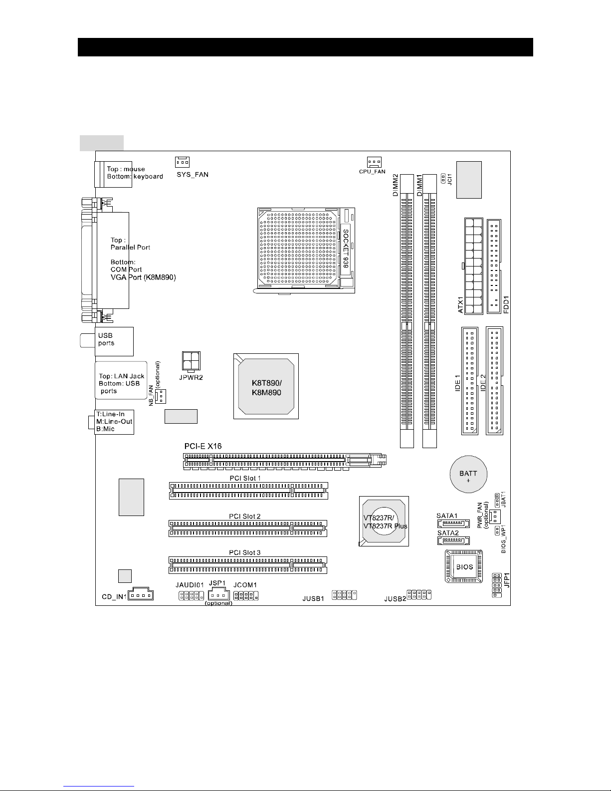
Layout

2
Specifications
CPU
l Supports Socket-939 for AMD K8 Athlon 64 FX / Athlon 64 / Athlon 64 X2 / Sempron
(Socket939) processor
l Supports up to Athlon64 3500+, 3800+, or higher CPU
(For the latest information about CPU, please visit http://www.msi.com.tw/program/
products/mainboard/mbd/pro_mbd_cpu_support.php )
Chipset
l Northbridge: VIA® K8T890 / K8M890
l Southbridge: VIA® VT8237R / VT8237R Plus
Main Memory
l Dual channel memory architecture ( DIMM1 must be first installed)
l 2 x 184-pin DIMM sockets, support DDR400/333 memory modules.
(For the updated supporting memory modules, please visit http://www.msi.com.tw/
program/products/mainboard/mbd/pro_mbd_trp_list.php )
Slots
l One PCI-E x16 Slot
l Three PCI Slots (32-bit v2.3 Master PCI bus)
Storage
l 2 x Ultra DMA 133/100
l 1 x Floppy
l 2 x Serial ATA (VT8237R/VT8237R Plus)
On-Board Peripherals
l External:
- 1 x PS/2 mouse connector
- 1 x PS/2 keyboard connector
- 1 x Parallel port
- 1 x COM port
- 1 x VGA port (K8M890)
- 4 x USB connectors
- 1 x RJ-45 connector
- 1 x Audio jack
l Internal:
- 1 x Intel/MSI standard Front Panel Pin-head
- 2 x Front USB pin-head (4 ports)
- 1 x COM pin-head
- 1 x CPU Fan connector
- 1 x System Fan connector
- 1 x Power Fan connector (Optional)
- 1 x Northbridge Fan connector (Optional)
- 1 x Clear CMOS connector
- 1 x Chassis Intrusion Switch connector
- 1 x Intel® Front Audio pin-head
- 2 x IDE(ATA133) connectors
- 1 x Floppy connector
- 1 x CD-in connector
- 2 x SATA connectors

3
Audio
l AC’97 link controller integrated in VIA 8237R / 8237R Plus chipset.
l 6-channel audio codec Realtek ALC655.
- Compliance with AC97 v2.3 Spec.
- Meet PC2001 audio performance requirement.
On-Board LAN
l RealtekR 8100C / 8110S (Optional)
- Integrated Fast Ethernet MAC and PHY in one chip.
- Supports 10Mb/s, 100Mb/s. and 1000Mb/s (1000Mb/s for 8110S only)
- Compliance with PCI 2.2.
- Supports ACPI Power Management
BIOS
l Award(LPC) Flash ROM
Dimension
l Micro-ATX Form Factor: 24.4 cm (L) x 22.4 cm (W)
Mounting
l 6 mounting holes
4
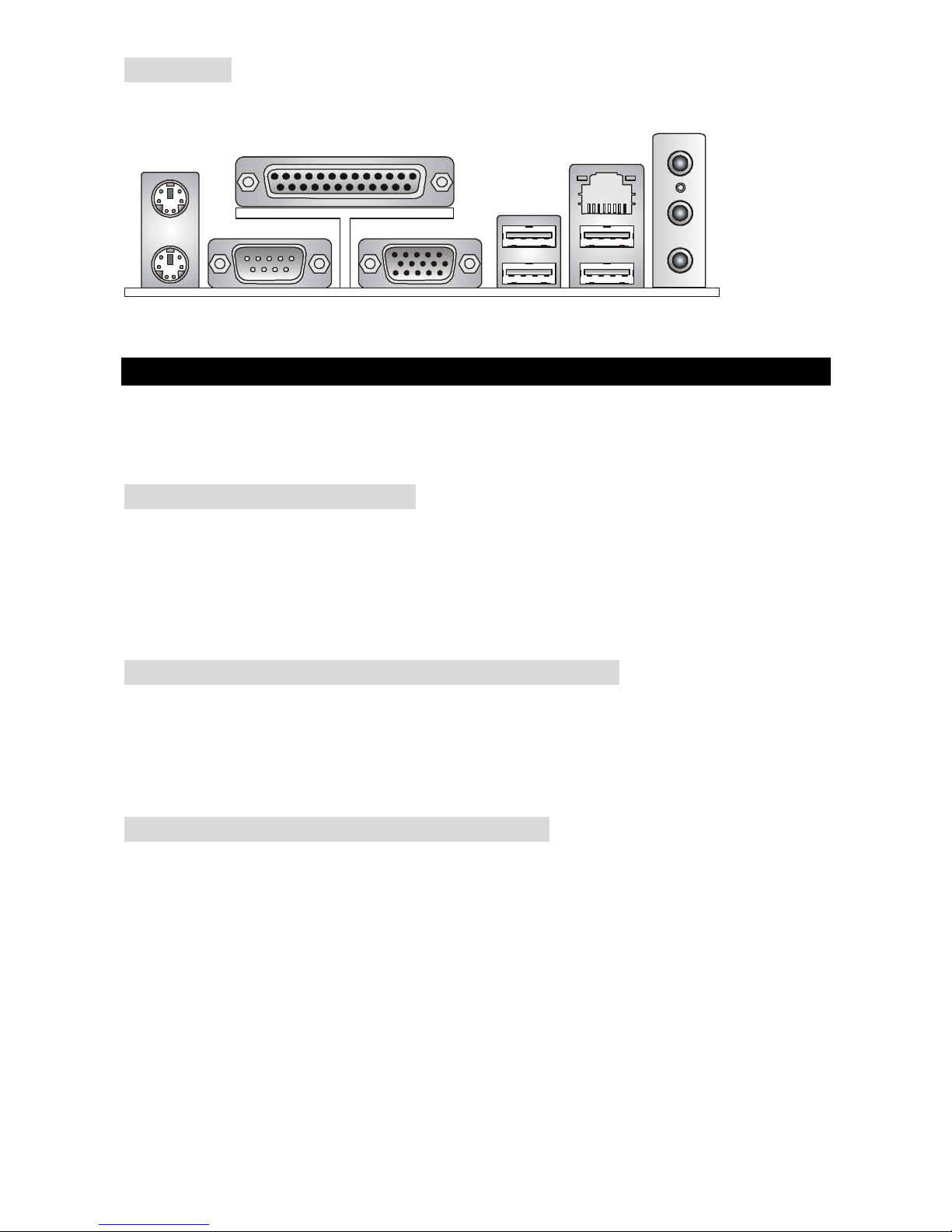
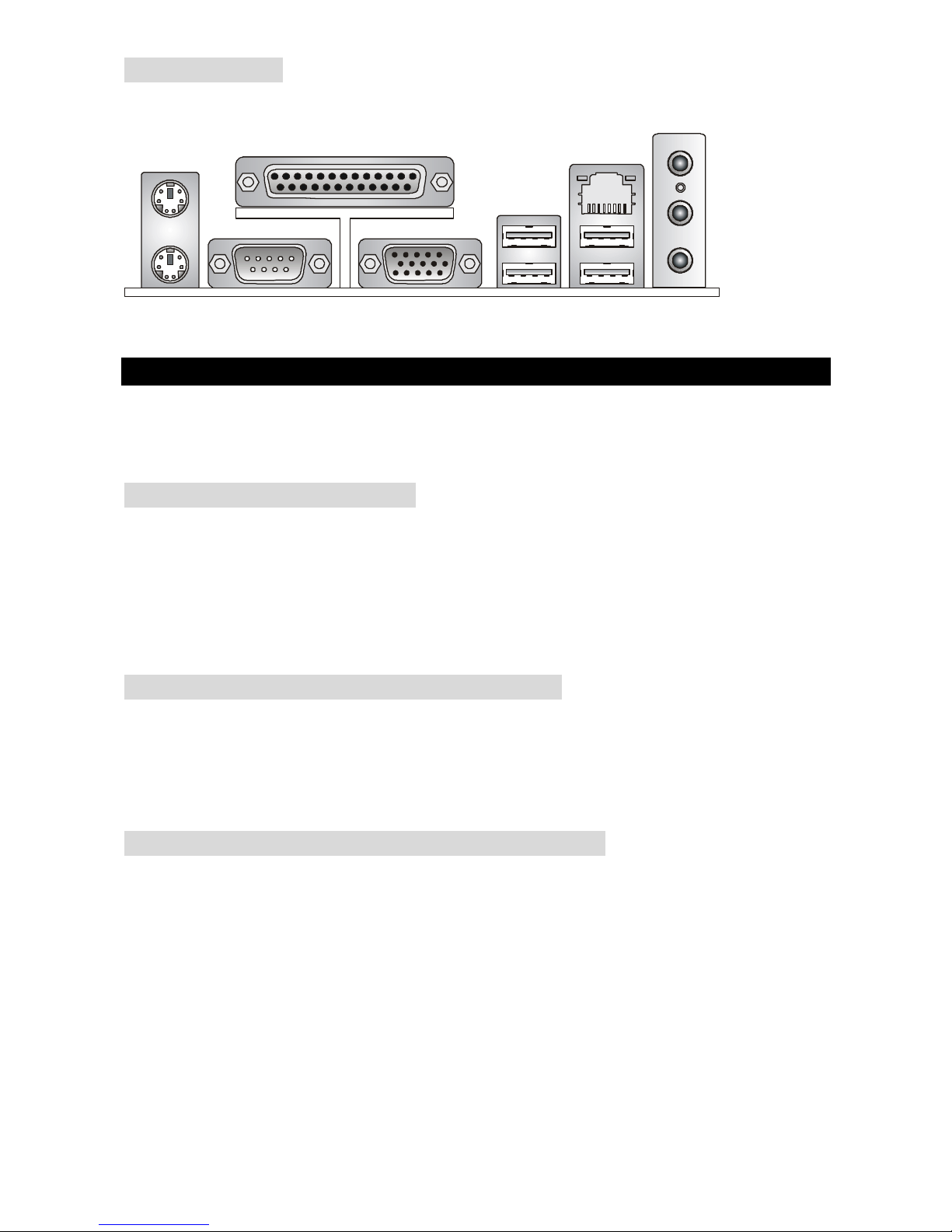
Rear Panel
The rear panel provides the following connectors:
Hardware Setup
This chapter tells you how to install the CPU, memory modules, and expansion cards, as well as
how to setup the jumpers on the mainboard. It also provides the instructions on connecting the
peripheral devices, such as the mouse, keyboard, etc. While doing the installation, be careful in
holding the components and follow the installation procedures.
Central Processing Unit: CPU
The mainboard supports AMD® Athlon64 / Athlon64 FX / Athlon64 X2 / Sempron processor. The
mainboard uses a CPU socket called Socket-939 for easy CPU installation. When you are
installing the CPU, make sure the CPU has a heat sink and a cooling fan attached on the top to
prevent overheating. If you do not have the heat sink and cooling fan, contact your dealer to
purchase and install them before turning on the computer.
(For the latest information about CPU, please visit
http://www.msi.com.tw/program/products/mainboard/mbd/pro_mbd_cpu_support.php )
Example of CPU Core Speed Derivation Procedure
If CPU Clock = 200MHz
Core/Bus ratio = 12
then CPU core speed = Host Clock x Core/Bus ratio
= 200MHz x 12
= 2.4 GHz
CPU Installation Procedures for Socket 939
1. Please turn off the power and unplug the power cord before installing the CPU.
2. Pull the lever sideways away from the socket. Make sure to raise the lever up to a
90-degree angle.
3. Look for the gold arrow on the CPU. The CPU can only fit in the correct orientation. Lower
the CPU down onto the socket.
4. If the CPU is correctly installed, the pins should be completely embedded into the socket
and can not be seen. Please note that any violation of the correct installation procedures
may cause permanent damages to your mainboard.
5. Press the CPU down firmly into the socket and close the lever. As the CPU is likely to
move while the lever is being closed, always close the lever with your fingers pressing
tightly on top of the CPU to make sure the CPU is properly and completely embedded into
the socket.
Parallel port
COM port
Mouse
Keyboard
USB ports
USB ports
Line ln
Line Out
MIC
LAN
VGA port
(K8M890)
5
Installing AMD Athlon64 / Athlon64 FX / Athlon64 X2 / Sempron CPU
Cooler Set
When you are installing the CPU, make sure the CPU has a heat sink and a cooling fan attached
on the top to prevent overheating. If you do not have the heat sink and cooling fan, contact your
dealer to purchase and install them before turning on the computer.
1. Detach the shield of the backplate’s plaster.
2. Turn over the mainboard, and install the backplate to the proper position.
3. Turn over the mainboard again and place the mainboard on the flat surface. Locate the
two screw holes of the mainboard.
4. Align the retention mechanism and the backplate. Fix the retention mechanism and the
backplate with two screws.
5. Position the cooling set onto the retention mechanism. Hook one end of the clip to hook
first.
6. Press down the other end of the clip to fasten the cooling set on the top of the retention
mechanism.
7. Locate the Fix Lever, Safety Hook and the Fixed Bolt. Lift up the intensive fixed lever.
8. Fasten down the lever.
9. Make sure the safety hook completely clasps the fixed bolt of the retention mechanism.
MSI Reminds You...
While disconnecting the Safety Hook from the fixed bolt, it is necessary to keep an eye on your
fingers, because once the Safety Hook is disconnected from the fixed bolt, the fixed lever will
spring back instantly.
Memory
The mainboard provides two 184-pin unbuffered DDR333 / DDR400 DDR SDRAM, and supports
the memory size up to 2GB. To operate properly, at least one DIMM module must be installed.
(For the updated supporting memory modules, please visit
http://www.msi.com.tw/program/products/mainboard/mbd/pro_mbd_trp_list.php )
Install at least one DIMM module on the slots. Memory modules can be installed on the slots in
any order. You can install either single- or double-sided modules to meet your own needs.
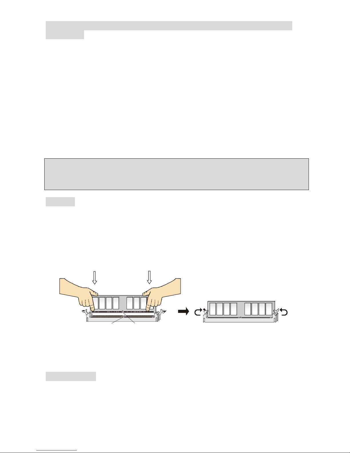
Installing DDR Modules
1. The DDR DIMM has only one notch on the center of module. The module will only fit in the
right orientation.
2. Insert the DIMM memory module vertically into the DIMM slot. Then push it in until the
golden finger on the memory module is deeply inserted in the socket.
3. The plastic clip at each side of the DIMM slot will automatically close.
Power Supply
The mainboard supports ATX power supply for the power system. Before inserting the power
supply connector, always make sure that all components are installed properly to ensure that no
damage will be caused. A 300W or above power supply is suggested.
Notch
Volt
6
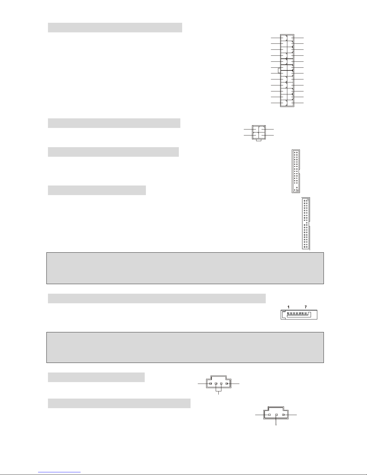
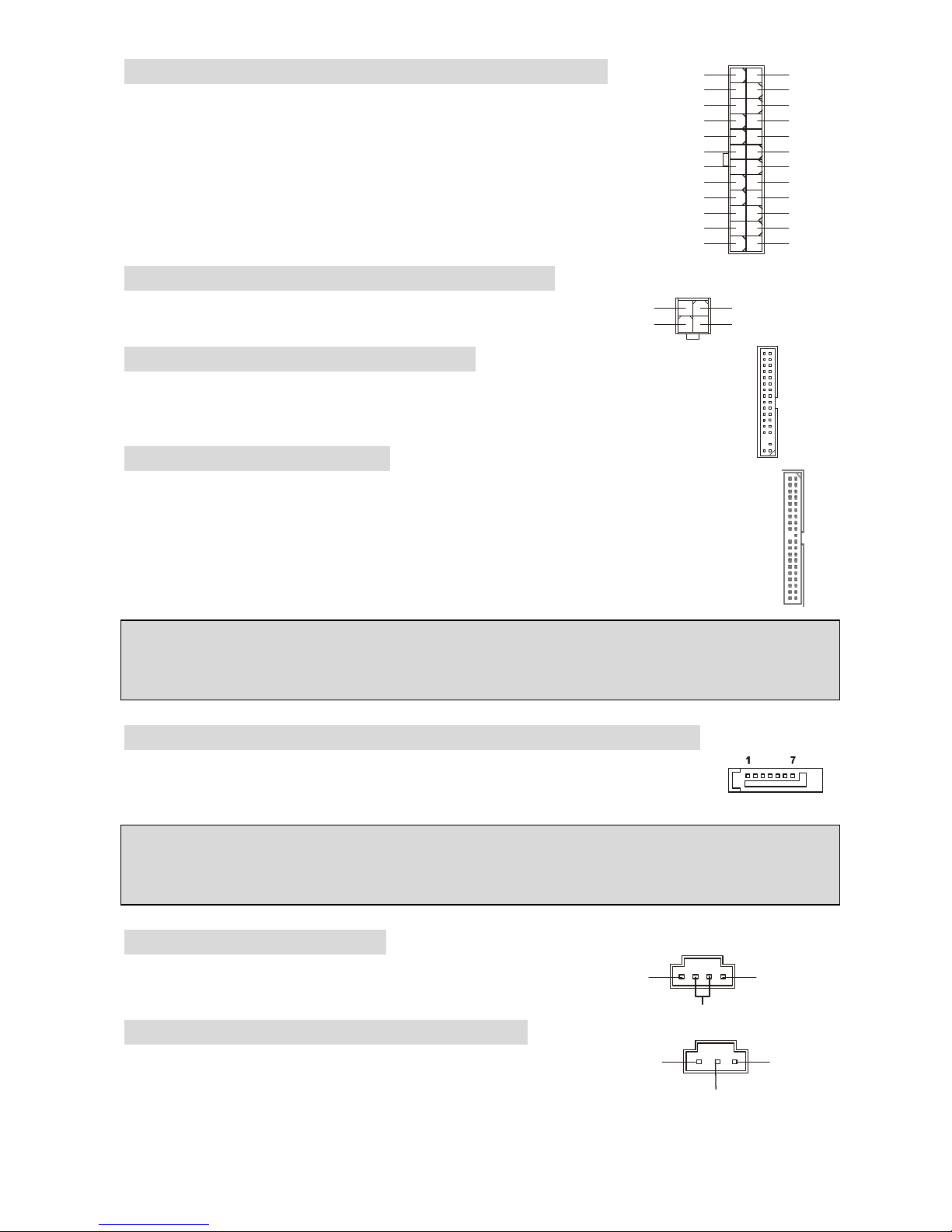
ATX 24-Pin Power Connector: ATX1
This connector allows you to connect an ATX 24-pin power supply. To
connect the ATX 24-pin power supply, make sure the plug of the power
supply is inserted in the proper orientation and the pins are aligned.
Then push down the power supply firmly into the connector.
You may use the 20-pin ATX power supply as you like. If you’d like to
use the 20-pin ATX power supply, please plug your power supply along
with pin 1 & pin 13. There is also a foolproof design on pin 11, 12, 23 &
24 to avoid wrong installation.
ATX 12V Power Connector: JPWR2
This 12V power connector is used to provide power to the CPU.
Floppy Disk Drive Connector: FDD
The mainboard provides a standard floppy disk drive connector that supports 360K,
720K, 1.2M, 1.44M and 2.88M floppy disk types.
IDE Connector: IDE1/IDE2
The mainboard has dual Ultra DMA 66/100 controller that provides PIO mode 0~4, Bus
Master, and Ultra DMA 66/100 function. You can connect up to four hard disk drives,
CD-ROM, 120MB Floppy and other devices.
The first hard drive should always be connected to IDE1. IDE1 can connect a Master
and a Slave drive. You must configure second hard drive to Slave mode by setting the
jumper accordingly.
MSI Reminds You...
If you install two hard disks on one cable, you must configure the second drive to Slave mode by
setting its jumper. Refer to the hard disk documentation supplied by hard disk vendors for jumper
setting instructions.
Serial ATA (8237R/8237R Plus) Connectors: SATA1/SATA2
The mainboard provides two high-speed Serial ATA interface ports. These ports
support Serial ATA data rates of 150MB/s and are fully compliant with Serial ATA
1.0 specification. Each Serial ATA connector can connect to 1 hard disk device.
MSI Reminds You...
Please do not fold the serial ATA cable in a 90-degree angle, which will cause the loss of data
during transmission.
CD-In Connector: CD_IN1
The connector is for CD-ROM audio connector.
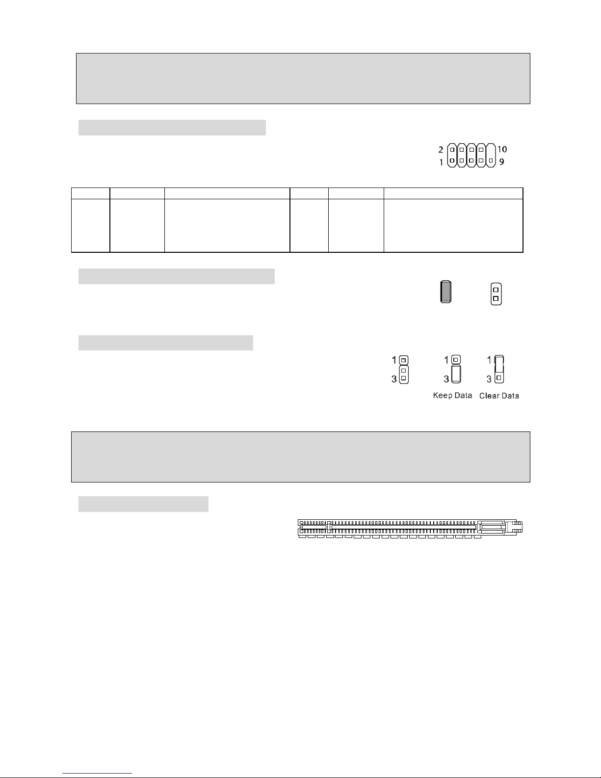
SPDIF-Out Connector: JSP1(optional)
This connector is used to connect SPDIF (Sony & Philips Digital
Interconnect Format) interface for digital audio transmission.
L
R
GND
1
3
4
2
GND
12V
GND
12V
1
12
24
13
+3.3V
+3.3V
-12V
+3.3V
GND GND
PS-ON#
+5V
GND GND
GND +5V
GND GND
Res
PWR OK
+5V 5VSB
+5V +12V
+5V +12V
GND NC
GND
SPDIF
VCC
7
GND
+12V
NC
GND
+12V
NC
GND
+12V
Sensor
CPU_FAN SYS_FAN PWR_FAN /
NB_FAN
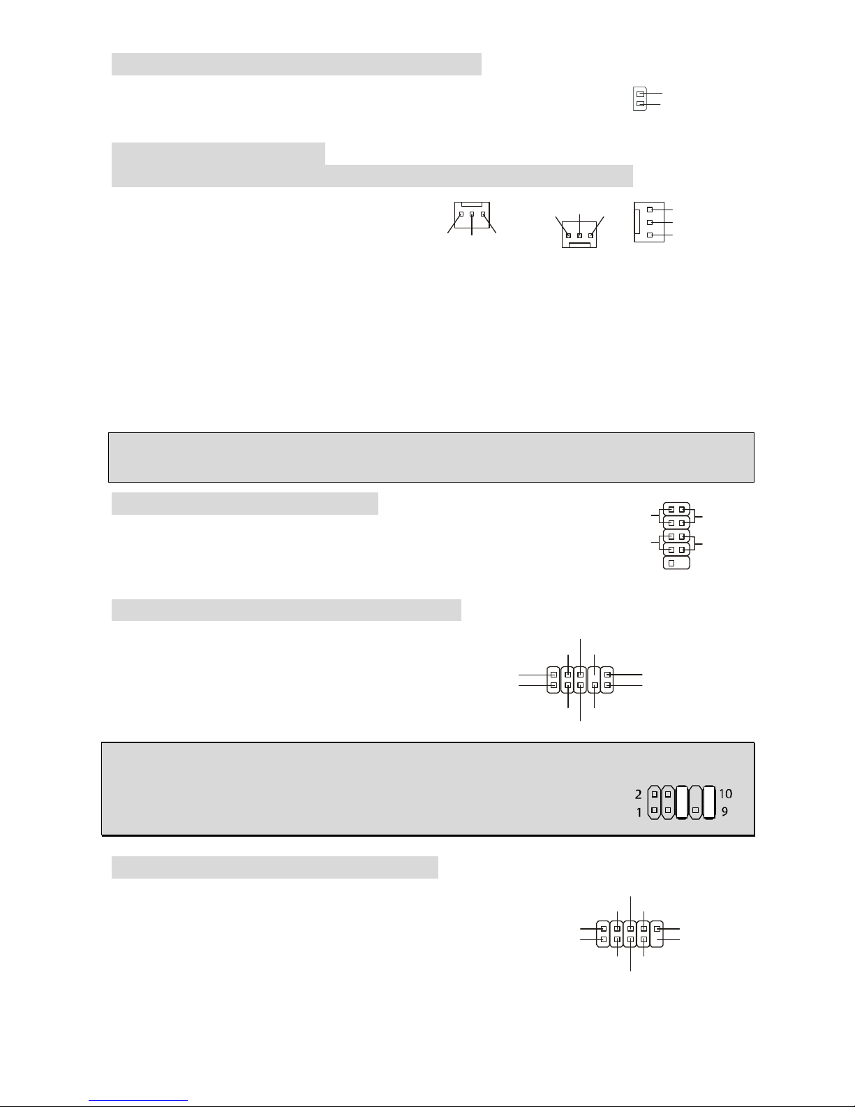
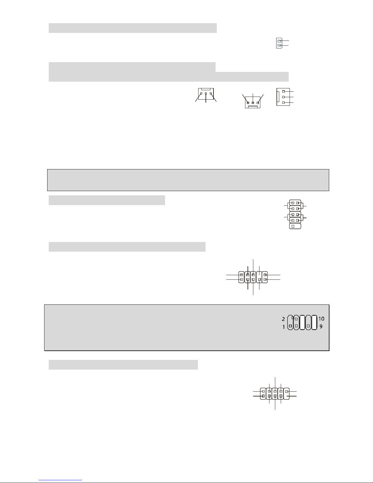
Chassis Intrusion Switch Connector: JCI1
This connector is connected to a 2-pin chassis switch. JCI1 is compliant
with Intel® Front Panel I/O Connectivity Design Guide.
Fan Power Connectors:
CPU_FAN/SYS_FAN/PWR_FAN(optional)/NB_FAN(optional)
The 4-pin CPU_FAN (processor fan), 3-pin
SYS_FAN (system fan), PWR_FAN (power
fan) and NB_FAN (Northbridge) support
system cooling fan with +12V. CPUFAN
can support three- or four-pin head
connector.
When connecting the wire to the connectors, always take note that the red wire is the positive
and should be connected to the +12V, the black wire is Ground and should be connected to GND.
If the mainboard has a System Hardware Monitor chipset on-board, you must use a specially
designed fan with speed sensor to take advantage of the CPU fan control.
MSI Reminds You...
Always consult the vendors for the proper CPU cooling fan.
Front Panel Connectors: JFP1
The mainboard provides two front panel connectors for electrical
connection to the front panel switches and LEDs. JFP1 is compliant with
Intel® Front Panel I/O Connectivity Design Guide.
Front Panel Audio Connector: JAUDIO1
The front panel audio connector allows you to
connect to the front panel audio and is
compliant with Intel® Front Panel I/O
Connectivity Design Guide.
MSI Reminds You...
If you do not want to connect to the front audio header, pins 5 & 6, 9 & 10 have
to be jumpered in order to have signal output directed to the rear audio ports.
Otherwise, the Line-Out connector on the back panel will not function.
Front USB Connector: JUSB1/JUSB2
The mainboard provides two standard USB 2.0 pin headers
JUSB1&JUSB2. USB2.0 technology increases data transfer
rate up to a maximum throughput of 480Mbps, which is 40
times faster than USB 1.1, and is ideal for connecting
high-speed USB interface peripherals such as USB HDD,
digital cameras, MP3 players, printers, modems and the like.
2
1
GND
CINTRO
JFP1
Power
LED
HDD
LED
Reset
Switch
Power
Switch
192
10
(2)AUD_GND
AUD_VCC
AUD_RET_R
Key
AUD_RET_L(10)
(1)AUD_MIC
AUD_MIC_BIAS
AUD_FPOUT_R
HP_ON
AUD_FPOUT_L(9)
(2)VCC
USB1- GND
GND
USB0-
USB0+
USB1+
USB0C(10)
(1)VCC Key(9)
8
MSI Reminds You...
Please note that the pins of VCC & GND must be connected correctly or it may cause some
damage
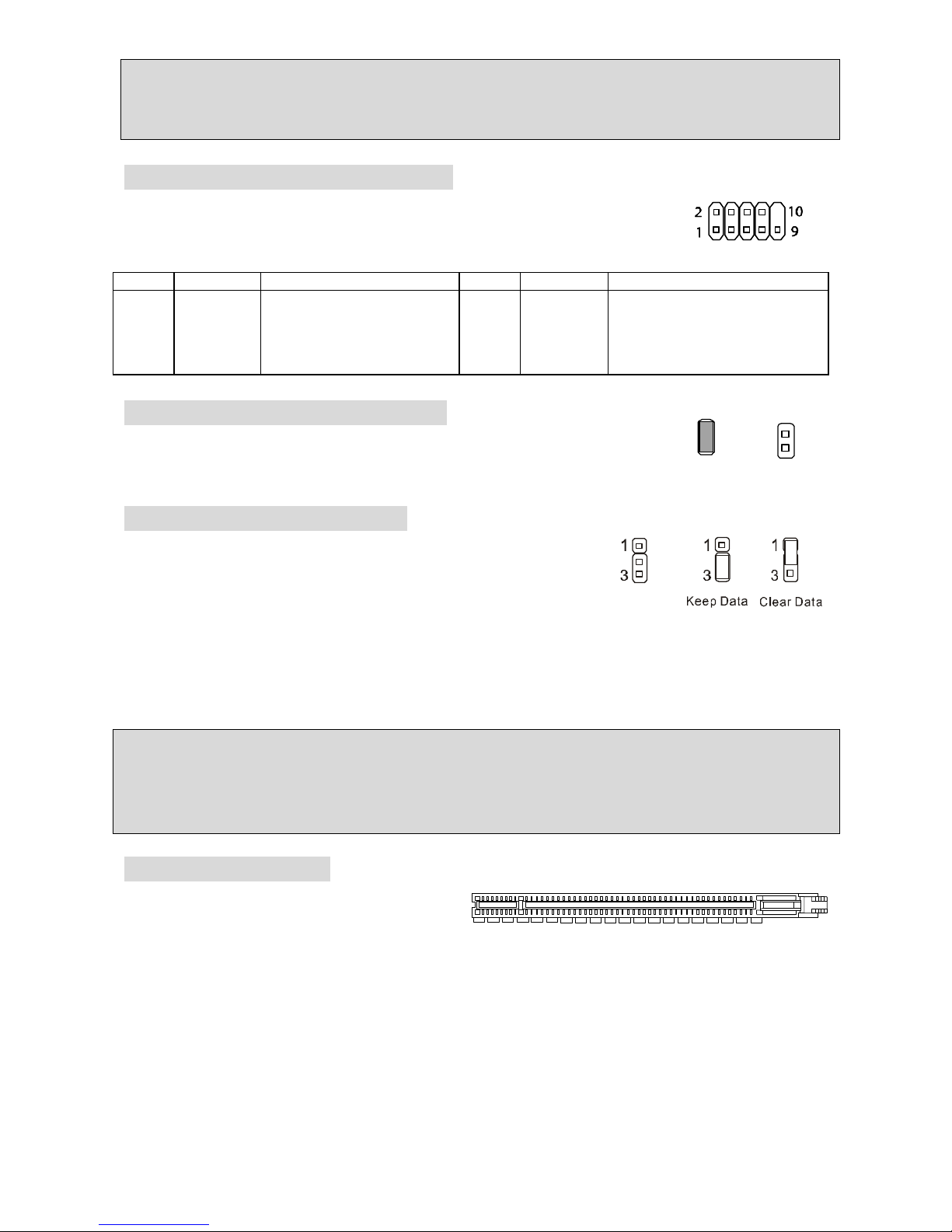
Serial Port Connector: JCOM1
The mainboard offers one 9-pin male DIN connector COM 1 (on the rear
panel), and one optional serial port JCOM1. Both are 16550A high speed
communication ports that send/receive 16 bytes FIFOs. You can attach a
serial mouse or other serial device directly to them.
PIN
SIGNAL
DESCRIPTION PIN
SIGNAL
DESCRIPTION
1
3
5
7
9
DCD
SOUT
GND
RTS
RI
Data Carry Detect
Receive Data Transmit
Data
Request To Send Ring
Indicate
2
4
6
8
10
SIN
DTR
DSR
CTS
X
Serial in or receive data
Serial out or transmit data
Data Set Ready
Clear To Send
X
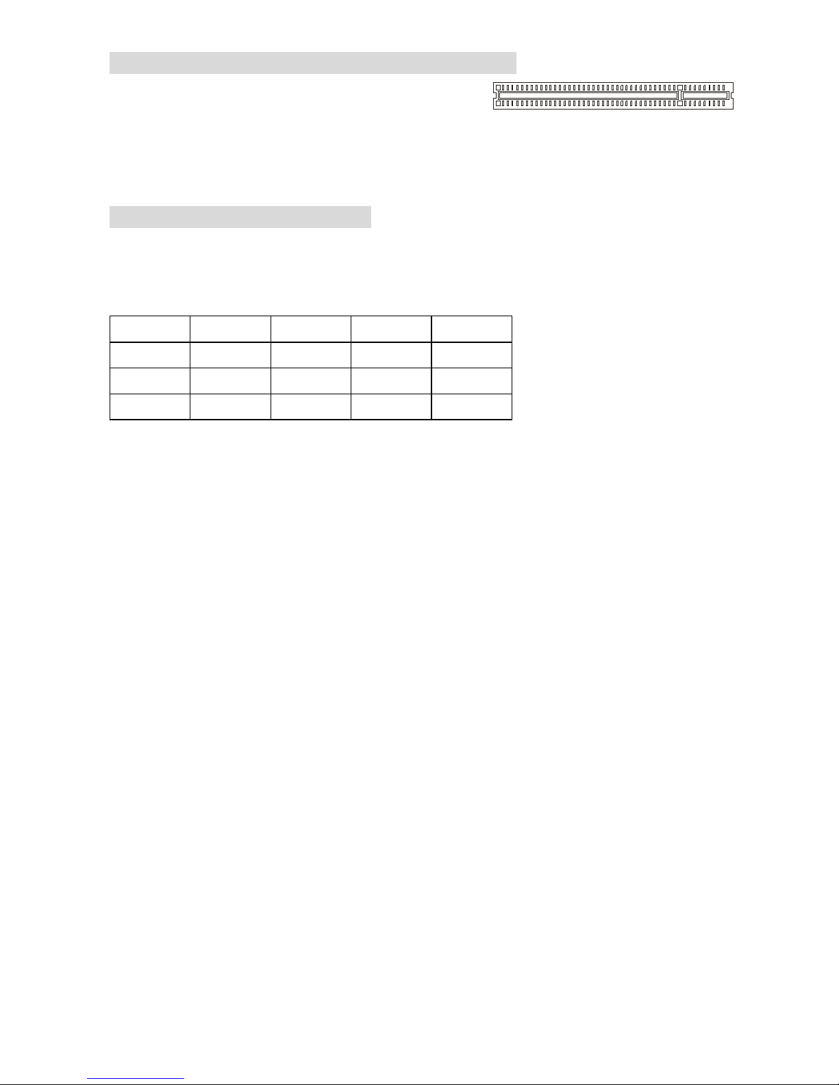
BIOS Flash Jumper: BIOS_WP1
This jumper is used to lock or unlock the boot block area on BIOS. When
unlocked, the BIOS boot block area can be updated. When locked, the
BIOS boot block area cannot be updated.
Clear CMOS Jumper: JBAT1
There is a CMOS RAM on board that has a power supply from
external battery to keep the data of system configuration. With the
CMOS RAM, the system can automatically boot OS every time it
is turned on. If you want to clear the system configuration, use the
JBAT1 (Clear CMOS Jumper) to clear data. Follow the instructions in the image to clear the data.
MSI Reminds You...
You can clear CMOS by shorting 1-2 pin while the system is off. Then return to 2-3 pin position.
Avoid clearing the CMOS while the system is on, which will damage the mainboard.
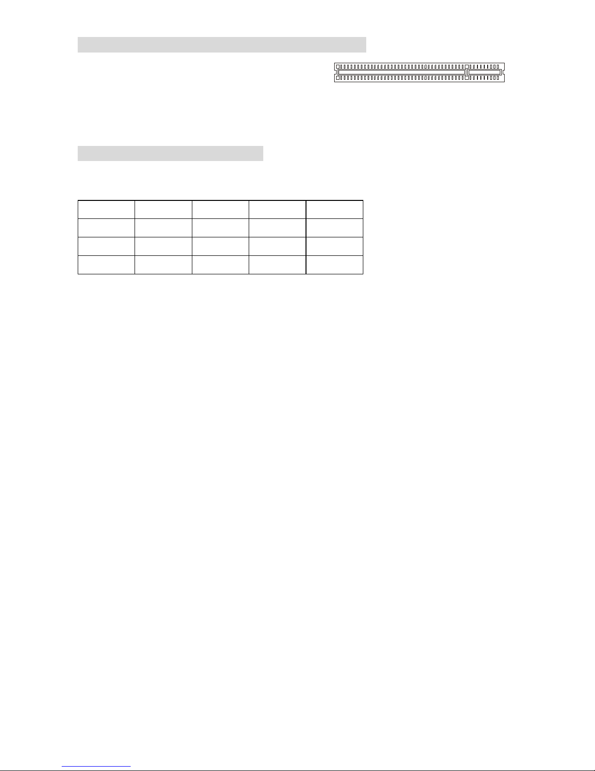
PCI Express x16 Slot
The PCI Express slot, as a high-bandwidth,
low pin count, serial, interconnect technology,
support Intel highest performance desktop
platforms utilizing the Intel Pentium 4 processor with HT Technology with these platform benefits.
You can insert the expansion cards to meet your needs. When adding or removing expansion
cards, make sure that you unplug the power supply first. PCI Express architecture provides a
high performance I/O infrastructure for Desktop Platforms with transfer rates starting at 2.5 Giga
transfers per second over a PCI Express x1 lane for Gigabit Ethernet, TV Tuners, 1394
controllers, and general purpose I/O. Also, desktop platforms with PCI Express Architecture will
be designed to deliver highest performance in video, graphics, multimedia and other
sophisticated applications. Moreover, PCI Express architecture provides a high performance
graphics infrastructure for Desktop Platforms doubling the capability of existing AGP8x designs
with transfer rates of 4.0 GB/s over a PCI Express x16 lane for graphics controllers, while PCI
Express x1 supports transfer rate of 250 MB/s.
BIOS Flash
Locked
BIOS Flash
Unlocked
9
PCI (Peripheral Component Interconnect) Slots
The PCI slots allow you to insert the expansion cards
to meet your needs. When adding or removing
expansion cards, make sure that you unplug the
power supply first. Meanwhile, read the documentation for the expansion card to make any
necessary hardware or software settings for the expansion card, such as jumpers, switches or
BIOS configuration.
PCI Interrupt Request Routing
The IRQ, abbreviation of interrupt request line and pronounced I-R-Q, are hardware lines over
which devices can send interrupt signals to the microprocessor. The PCI IRQ pins are typically
connected to the PCI bus INT A# ~ INT D# pins as follows:
Order1 Order2 Order3 Order4
PCI Slot 1 INT A# INT B# INT C# INT D#
PCI Slot 2 INT B# INT C# INT D# INT A#
PCI Slot 3 INT C# INT D# INT A# INT B#
10
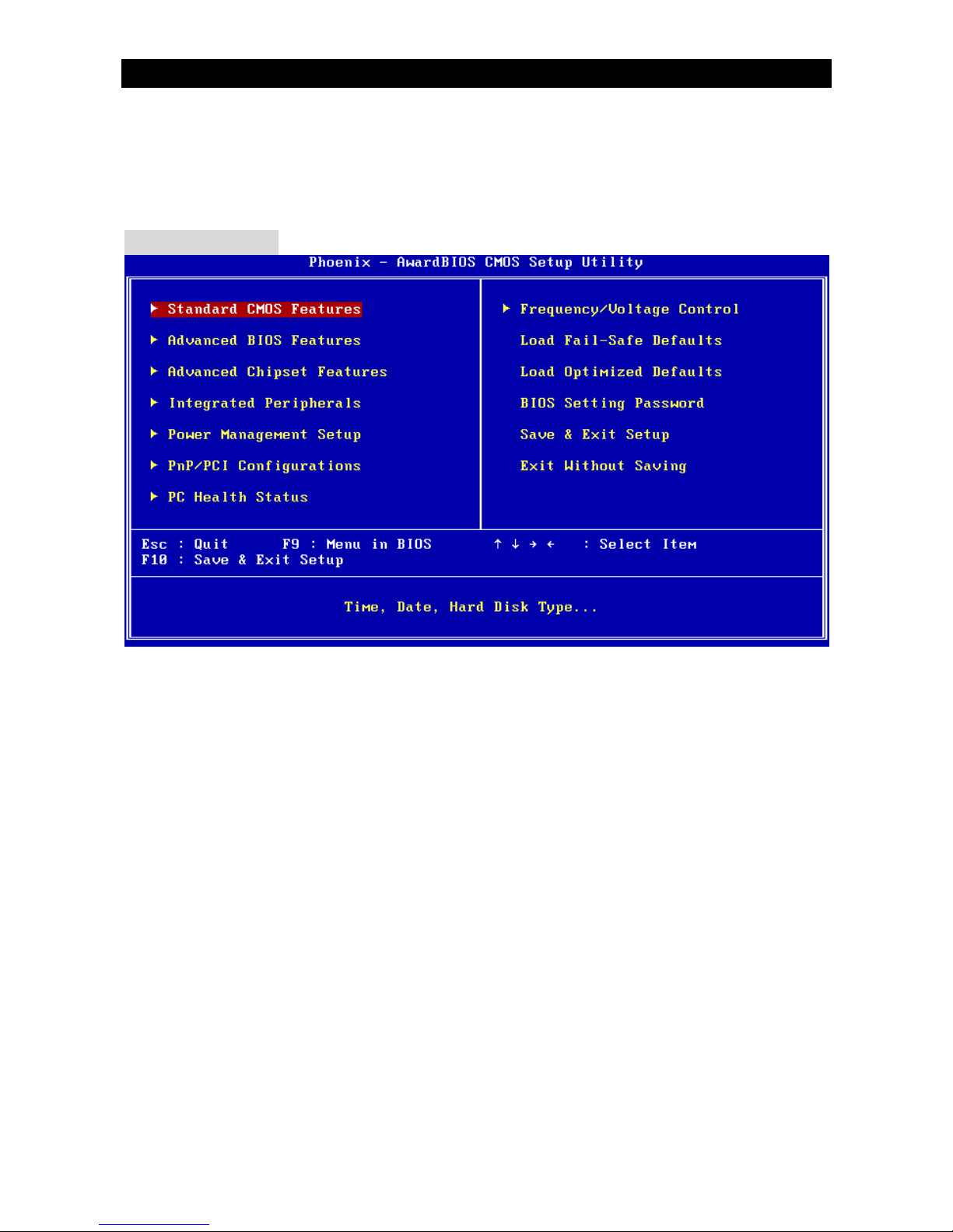
BIOS Setup
Power on the computer and the system will start POST (Power On Self Test) process. When the
message below appears on the screen, press <DEL> key to enter Setup.
DEL: Setup
If the message disappears before you respond and you still wish to enter Setup, restart the
system by turning it OFF and On or pressing the RESET button. You may also restart the system
by simultaneously pressing <Ctrl>, <Alt>, and <Delete> keys.
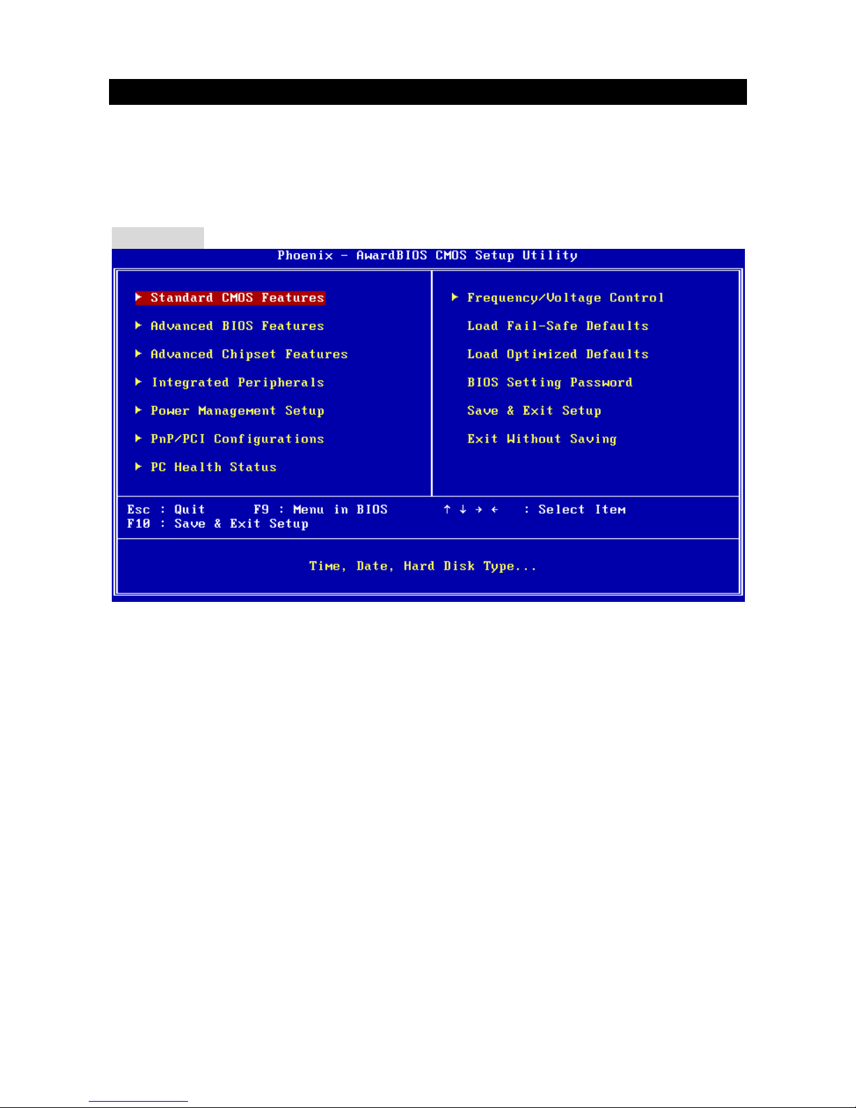
Main Page
Standard CMOS Features
Use this menu for basic system configurations, such as time, date etc.
Advanced BIOS Features
Use this menu to setup the items of Award special enhanced features.
Advanced Chipset Features
Use this menu to change the values in the chipset registers and optimize your system
performance.
Integrated Peripherals
Use this menu to specify your settings for integrated peripherals.
Power Management Setup
Use this menu to specify your settings for power management.
PnP/PCI Configuration
This entry appears if your system supports PnP/PCI.
PC Health Status
This entry shows your PC health status.
11
Frequency/Voltage Control
Use this menu to specify your settings for frequency/voltage control.
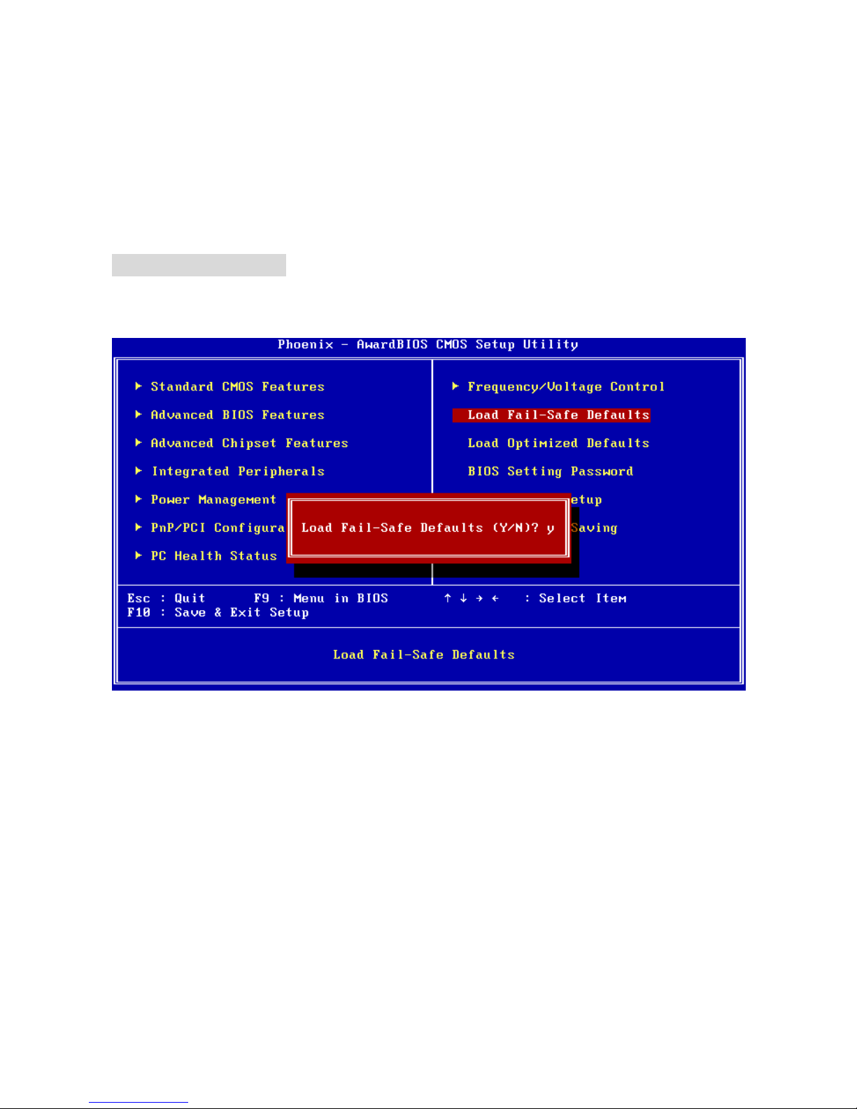
Load Fail-Safe Defaults
Use this menu to load the BIOS default values that are factory settings for system operations.
Load Optimized Defaults
Use this menu to load factory default settings into the BIOS for stable system performance
operations.
BIOS Setting Password
Use this menu to set password.
Save & Exit Setup
Save changes to CMOS and exit setup.
Exit Without Saving
Abandon all changes and exit setup.
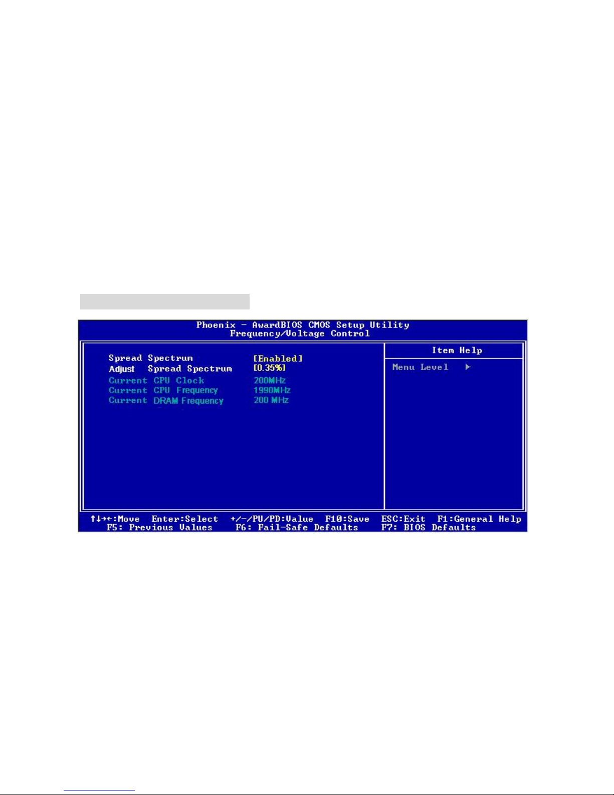
Frequency/Voltage Control
Spread Spectrum
When the motherboard’s clock generator pulses, the extreme values (spikes) of the pulses
create EMI (Electromagnetic Interference). The Spread Spectrum function reduces the EMI
generated by modulating the pulses so that the spikes of the pulses are reduced to flatter curves.
If you do not have any EMI problem, leave the setting at [Disabled] for optimal system stability
and performance. But if you are plagued by EMI, select the desired range for EMI reduction.
Remember to disable Spread Spectrum function if you are overclocking, because even a slight
jitter can introduce a temporary boost in clock speed which may just cause your overclocked
processor to lock up.
12
Current CPU Clock
It shows the current clock of CPU. Read-only.
Current CPU Frequency
It shows the current frequency of CPU. Read-only.
Current DRAM Frequency
It shows the current frequency of DRAM. Read-only.
Load BIOS Defaults
You can load the default values provided by the mainboard manufacturer for the stable
performance.
13
Introduction
Félicitations, vous venez d’acquérir une carte mère Micro-ATX K8T890M2-V/K8M890M2-V
Sèries (MS-7139 v2.x). La K8T890M2-V / K8M890M2-V Series est bas é e sur les chipsets VIA
®
K8T890 / K8M890 & VIA® VT8237R / VT8237R Plus offrant un système très performant. La carte
fonctionne avec les processeurs AMD® 64 Socket 939, la K8T890M2-V / K8M890M2-V Series
est très performante et offre une solution adaptée tant aux professionnels qu’aux particuliers.
Layout

14
Spécificités
CPU
l Supporte Socket 939 pour AMD K8 Athlon 64 FX / Athlon 64 / Athlon 64 X2 / Sempron
(Socket939) processeur
l Supporte jusqu'à Athlon64 3500+, 3800+, ou processeur supérieur
(Pour les dernières mises à jours concernant les CPU, vous pouvez visiter
http://www.msi.com.tw/program/products/mainboard/mbd/pro_mbd_cpu_support.php)
Chipset
l Northbridge: VIA® K8T890 / K8M890
l Southbridge: VIA® VT8237R / VT8237R Plus
Mémoire Principale
l Architecture de mémoire Dual channel (DIMM1 doit d’abord être installé)
l 2 DIMM 184 broches, supportant les modules de mémoire DDR400/333.
(Pour une mise à jour sur les modèles de mémoires supportés, veuillez visiter
http://www.msi.com.tw/program/products/mainboard/mbd/pro_mbd_trp_list.php)
Slots
l Un slot PCI-E x16
l Trois slots PCI (32-bit v2.3 Master PCI bus)
Stockage
l 2 x Ultra DMA 133/100
l 1 x Floppy
l 2 X Serial ATA (VT8237R/VT8237R Plus)
Périphériques intégrés
l Externe:
- 1 x connecteur souris PS/2
- 1 x connecteur clavier PS/2
- 1 x port Parallèle
- 1 x port COM
- 1 x port VGA (k8M890)
- 4 x connecteurs USB
- 1 x connecteur RJ-45
- 1 x Audio jack
l Interne:
- 1 x connecteur Front Panel Intel/MSI standard
- 2 x connecteurs Front USB (4 ports)
- 1 x connecteur COM
- 1 x connecteur ventilateur de CPU
- 1 x connecteur ventilateur de système
- 1 x connecteur ventilateur de power (Optionnel)
- 1 x connecteur ventilateur de Northbridge (Optionnel)
- 1 x connecteur Clear CMOS
- 1 x connecteur Switch Chassis Intrusion
- 1 x connecteur Intel® Front Audio
- 2 x connecteurs IDE(ATA133)
- 1 x connecteur Floppy
- 1 x connecteur CD-in
- 2 x connecteurs SATA

15
Audio
l Contrôleur link AC’97 integré dans le chipset VIA 8237R / 8237R Plus
l Codec audio Realtek ALC655 6 canaux
- Compatible avec les Spec. AC97 v2.3
- Requiert les performances audio PC2001
LAN Intégré
l RealtekR 8100C / 8110S (Optionnel)
- Fast Ethernet MAC et PHY intégré dans une puce.
- Supporte 10Mb/s, 100Mb/s. et1000Mb/s (1000Mb/s pour 8110S uniquement)
- Compatible avec PCI 2.2.
- Supporte l’ACPI Power Management
BIOS
l Flash ROM Award(LPC)
Dimension
l Format Micro-ATX : 24.4 cm (L) x 22.4 cm (W)
Montage
l 6 trous de montage
16
Panneau Arrière
Le panneau arrière procure les connecteurs suivants:
Installation Matériel
Ce chapitre vous indique comment installer le processeur, barrettes de mémoire et cartes
d’extension. Lors de l’installation des matériels, veuillez suivre les instructions de montage pour
éviter d’endommager quoi que ce soit.
Central Processing Unit: CPU
La carte supporte les processeurs AMD® Athlon64 / Athlon64 FX / Athlon64 X2 / Sempron. Elle
utilise le Socket-939 pour une installation plus simple. Assurez-vous que vous possédez bien un
ventilateur + dissipateur pour éviter la surchauffe. Si vous ne savez pas quel ventilateur utiliser,
veuillez contacter votre revendeur avant de mettre en marche votre PC. (Pour une mise à jour
sur les CPU, veuillez visiter
http://www.msi.com.tw/program/products/mainboard/mbd/pro_mbd_cpu_support.php)
Procédure de dérivation du CPU Core Speed
Si Horloge CPU = 200MHz
Multiplicateur = 12
Alors Vitesse CPU = Horloge x Multiplicateur
= 200MHz x 12
= 2.4 GHz
Procédure d’installation du CPU pour Socket 939
1. Veuillez éteindre ou débrancher le PC avant d’installer le CPU.
2. Tirer le levier qui se trouve sur le côté du socket. Assurez-vous que celui-ci est bien relevé
(position 90°).
3. Chercher la marque dorée sur le CPU. La marque dorée doit pointer vers le pivot du levier.
Le CPU peut ne s’installer que dans une seule position.
4. Si le CPU est correctement installé, les pattes doivent être complètement insérées dans le
socket et ne plus être visibles. Veuillez noter qu’une mauvaise installation endommage à
coup sur le processeur ainsi que la carte mère.
5. Appuyer sur le CPU et baisser le levier. Ainsi le CPU ne peut plus bouger et reste fixe sur
le socket.
Parallel port
COM port
Mouse
Keyboard
USB ports
USB ports
Line ln
Line Out
MIC
LAN
VGA port
(K8M890)

17
Installation du ventilateur de CPU AMD Athlon64 / Athlon64 FX /
Athlon64 X2 / Sempron CPU Cooler Set
Quand vous installerez votre CPU, assurez vous que le CPU possède un système de
refroidissement pour prévenir les surchauffes. Si vous ne poss édez pas de système de
refroidissement, contactez votre revendeur pour vous en procurer un et installez le avant
d’allumer l’ordinateur.
1. Détacher la protection
2. Retourner la carte mère et installer la plaque métallique
3. Retourner la carte mère et localiser les deux trous de vis sur la carte mère.
4. Aligner le mécanisme de rétention et la plaque métallique Fixer le mécanisme de
rétention et la plaque métallique avec les vis.
5. Positionner le ventilateur sur le mécanisme de rétention. Attacher tout d’abord un coté .
6. Appuyer sur l’autre coté pour attacher le ventilateur sur le haut du mécanisme de
rétention.
7. Localiser le levier de fixation et le crochet de sécurité. Relever le levier.
8. Abaisser le levier.
9. S’assurer que le crochet est sécurisé ( avec le mécanisme de rétention).
MSI Vous Rappelle...
Lorsque vous déconnectez le crochet, il est nécessaire de garder un oeil sur vos doigts car une
fois le crochet déconnecté, celui-ci reprend sa position initial du à son ressort.
Mémoire
La carte mère possède deux slots (184 broches) pour modules de mémoire DDR333 / DDR400
DDR SDRAM, et supporte un maximum de mémoire jusqu’à 2GB. Pour fonctionner
correctement, il faut au moins installer un module de mémoire DIMM. (Pour les dernières mises
à jours de mémoire supportées, merci de visiter
http://www.msi.com.tw/program/products/mainboard/mbd/pro_mbd_trp_list.php )
Installer au moins un module DIMM sur les slots. L’installation des modules de mémoires n’a pas
de sens particulier. Vous pouvez installer soit des modules simples ou doubles faces selon vos
besoins.
1. Le DDR DIMM ne possède qu’une encoche en son centre. Ainsi il n’est possible de
monter le module que dans un seul sens
2. Insérez le module de mémoire DIMM verticalement dans le slot. Puis appuyez dessus.
3. Le clip en plastique situé de chaque côté du module va se fermer automatiquement.
Alimentation
La carte mère supporte les alimentations ATX. Avant de brancher le connecteur d’alimentation,
Il faut toujours vous assurer que tous les composants sont bien installés afin de ne pas les
endommager. Une alimentation 300W ou supérieur est préconisée.
Notch
Volt
18
Connecteur d’alimentation ATX 24 broches: ATX1
Ce connecteur vous permet de connecter l’alimentation ATX 24-pin.
Pour ce faire assurez-vous que le connecteur est bien positionné dans
le bon sens. Puis appuyer sur le câble.
Vous pouvez aussi utiliser une alimentation 20 broches, veuillez
brancher votre alimentation d'énergie avec le pin1 et le pin 13. Il y a
également une conception indéréglable sur le pin 11, 12. 23 et 24 pour
éviter l'installation fausse.
Connecteur d’alimentation ATX 12V: JPWR2
Le connecteur d’alimentation 12V est utilisé pour alimenter le CPU.
Connecteur Floppy Disk Drive: FDD
La carte offre un connecteur standard floppy disk drive (lecteur de disquette) qui
supporte les disques 360K, 720K, 1.2M, 1.44M et 2.88M.
Connecteur IDE: IDE1/IDE2
La carte mère possède un double contrôleur Ultra DMA 66/100 qui procure les fonctions
PIO mode 0~4, Bus Master, et Ultra DMA 66/100. Vous pouvez connecter jusqu’à 4
matériels (disques durs, CD-ROM, 120MB Floppy).
Le premier disque dur doit être connecté sur l’IDE1. L’IDE1 peut recevoir un matériel
Maître et un Esclave. Vous devez configurer le second disque en mode Esclave et ce à
l’aide du cavalier situé à l’arrière.
MSI Vous Rappelle...
Si vous voulez installer deux disques durs, vous devez configurer le second en Esclave en
configurant le cavalier. Se référer à la documentation du disque dur pour les instructions.
Connecteurs Serial ATA (8237R/8237R Plus): SATA1/SATA2
La carte mère procure deux ports d’interface haute vitesse Serial ATA. Elle
supporte la de serial ATA (taux de transfert 150 MB/s) et sont entièrement
compatibles avec le Serial ATA 1.0. Chaque connecteur peut être connecté à un disque dur..
MSI Vous Rappelle...
Ne pas tordre le câble à 90° afin de ne pas l’endommager et éviter les pertes de données lors du
transfert.
Connecteur CD-In: CD_IN1
Le connecteur est destiné au branchement audio du CD-ROM
Connecteur SPDIF-Out : JSP1(Optionnel)
Ce connecteur est utilisé pour connecter l’interface SPDIF (Sony &
Philips Digital Interconnect Format) pour une transmission audio
digital
L
R
GND
1
3
4
2
GND
12V
GND
12V
1
12
24
13
+3.3V
+3.3V
-12V
+3.3V
GND GND
PS-ON#
+5V
GND GND
GND +5V
GND GND
Res
PWR OK
+5V 5VSB
+5V +12V
+5V +12V
GND NC
GND
SPDIF
VCC
19
GND
+12V
NC
GND
+12V
NC
GND
+12V
Sensor
CPU_FAN SYS_FAN PWR_FAN /
NB_FAN
Connecteur Chassis Intrusion Switch : JCI1
Ce connecteur est relié à un chassis switch deux broches. JCI1 est
compatible avec l’Intel® Front Panel I/O Connectivity Design Guide..
Connecteurs d’alimentation du ventilateur:
CPU_FAN/SYS_FAN/PWR_FAN(Optionnel)/NB_FAN(Optionnel)
Le CPUFAN 4 broches (ventilateur de
processeur) et 3 broches SYS-FAN
(system fan) , PWR_FAN (power fan),
NB_FAN (Northbridge) supportent le +12V.
CPUFAN peut supporter 3 ou 4 broches.
Lors de la connexion du câble, assurez-vous que le fil rouge soit connecté au +12V et le fil noir
connecté au “GND“. Si la carte mère possède un système de gestion intégré, vous devez utiliser
un ventilateur ayant ces caractéristiques si vous voulez contrôler le ventilateur du CPU
MSI Vous rappelle...
Il faut toujours consulter votre revendeur au sujet du ventilateur.
Connecteur Front Panel: JFP1
La carte mère procure 2 connecteurs pour les branchements électriques
(LED disque dur…). JFP1 est compatible avec le Design Intel Front Panel
I/O Connectivity Design Guide
Connecteur Front Panel Audio: JAUDIO1
Le connecteur audio JAUDIO1 vous permet de
connecter l’audio en façade et est compatible
avec lntel ® Front Panel I/O Connectivity
Design Guide
MSI Vous rappelle...
Si vous ne voulez pas connecter l’audio en façade à l’aide des broches
5 & 6, 9 & 10 doivent être recouvertes par un cavalier pour envoyer le
signalvers les ports audio à l’arrière. Autrement le connecteur Line-Out à l’arrière ne
fonctionnera pas.
Connecteur Front USB : JUSB1/JUSB2
La carte mère procure deux connecteurs standard 2.0
JUSB1&JUSB2. La technologie USB 2.0 accroît le taux de
transfert jusqu’à 480Mbps, ce qui est 40 fois plus rapide que l’
USB 1.1. Idéal pour relier les périphériques à grande vitesse
d'interface d'USB tels qu'usb HDD, appareils-photo
numériques, Joueurs MP3, imprimantes, modems et
semblables.
2
1
GND
CINTRO
JFP1
Power
LED
HDD
LED
Reset
Switch
Power
Switch
192
10
(2)AUD_GND
AUD_VCC
AUD_RET_R
Key
AUD_RET_L(10)
(1)AUD_MIC
AUD_MIC_BIAS
AUD_FPOUT_R
HP_ON
AUD_FPOUT_L(9)
(2)VCC
USB1- GND
GND
USB0-
USB0+
USB1+
USB0C(10)
(1)VCC Key(9)
2
1
GND
CINTRO
20
MSI Vous Rappelle...
A noter que les broches VCC et GND doivent être correctement connecter afin d’éviter tout
endommagement.
Connecteur port de série: JCOM1
La carte mère offre un connecteur COM1 9-pin male DIN (sur le panneau
arrière), et un port de série optionnel JCOM1. Tous deux sont des ports de
communication haute vitesse 16550A qui envoie/reçoit 16 bytes FIFOs.
Vous pouvez y attaché une souris de série ou autre composants de série directement.
PIN
SIGNAL
DESCRIPTION PIN
SIGNAL
DESCRIPTION
1
3
5
7
9
DCD
SOUT
GND
RTS
RI
Data Carry Detect
Receive Data Transmit
Data
Request To Send Ring
Indicate
2
4
6
8
10
SIN
DTR
DSR
CTS
X
Serial in or receive data
Serial out or transmit data
Data Set Ready
Clear To Send
X
Cavalier BIOS Flash : BIOS_WP1
Ce cavalier est utilisé pour ouvrir ou fermer le boot block area du BIOS.
Lorsqu’il est ouvert, le BIOS boot block area peut être mis à jour. Lorsqu’il
est fermé, il ne peut être mis à jour.
Cavalier Clear CMOS: JBAT1
La CMOS RAM intégré reçoit une alimentation d’une batterie
externe qui permet de garder les données de configuration du
système. Avec la CMOS RAM, le système peut automatiquement
booter avec les paramètres personnalisés du BIOS à chaque fois
que le PC est allumé. Si vous voulez effacer la configuration du système, utilisez le JBAT1
(Cavalier Clear CMOS) pour effacer les données. Suivez les instructions de l’image pour effacer
les données.
MSI Vous Rappelle...
Vous pouvez effacer les données en positionnant le cavalier sur les broches 1-2 quand le PC
n’est pas allumé. Puis il faut remettre le cavalier en position 2-3. Ne surtout pas effacer les
données lorsque le PC est en fonction, cela endommagera la carte mère.
PCI Express x16 Slot
Les slots PCI Express 16x possèdent une
large bande passante, supportent les
plateformes desktop Intel haute
performances utilisant le processeur Intel Pentium 4 avec la Technologie HT.
L’architecture PCI Express procure une infrastructure I/O haute performance architecture pour
plateformes Desktop avec un taux de transfert débutant à 2.5 Giga/s sur un PCI Express x1 pour
Gigabit Ethernet, TV Tuners, contrôleurs 1394, et autre usage I/O. Les plateformes Desktop
avec architecture PCI Express ont été conçu pour délivrer de hautes performances en vidéo,
graphisme, multimédia et autres applications sophistiquées.
De plus, l’architecture PCI Express procure une infrastructure performante pour le graphique et
double la capacité de l’AGP 8X avec un taux de transfert de données de 4.0 GB/s sur un PCI
Express x16 pour contrôleur graphique alors que le PCI Express x 1 supporte un taux de transfert
de 250 MB/s.
BIOS Flash
Locked
BIOS Flash
Unlocked
21
Slots PCI (Peripheral Component Interconnect)
Les slots PCI vous permettent d’insérer des cartes
d’expansion selon vos besoins. Lorsque vous ajoutez ou
enlever une carte d’expansion, assurez-vous que le PC n’est pas relié au secteur
En attendant, lisez la documentation pour que la carte d'expansion fasse touts les nécessaires
de matériel ou de logiciel pour cette carte, comme des pullovers, commutateurs ou configuration
de BIOS.
PCI Interrupt Request Routing
IRQ est l’abréviation de “interrupt request line”. Les IRQ sont des signaux émis par des matériels.
Les PCI IRQ sont connectés généralement au broches PCI bus INT A# ~ INT D# comme
suivant:
Order1 Order2 Order3 Order4
PCI Slot 1 INT A# INT B# INT C# INT D#
PCI Slot 2 INT B# INT C# INT D# INT A#
PCI Slot 3 INT C# INT D# INT A# INT B#
22
BIOS Setup
Lorsque le PC démarre le processus de POST (Power On Self Test) se met en route. Quand le
message ci-dessous apparaît, appuyer sur <DEL> pour accéder au Setup.
DEL: Setup
Si le message disparaît avant que n’ayez appuyé sur la touche, redémarrez le PC à l’aide du
bouton RESET. Vous pouvez aussi redémarrer en utilisant la combinaison de touches <Ctrl>,
<Alt>, et <Delete>.
Page Principale
Standard CMOS Features
Cette fonction permet le paramétrage des éléments standard du BIOS.
Advanced BIOS Features
Cette fonction permet de paramétrer des éléments avancés du BIOS.
Advanced Chipset Features
Cette option vous permet de paramétrer les éléments relatifs au registre du chipset, permettant
ainsi d’optimiser les performances de votre système.
Integrated Peripherals
Utiliser ce menu pour paramétrer les périphériques intégrés.
Power Management Setup
Utilisez ce menu pour appliquer vos choix en ce qui concerne le power management.
PNP/PCI Configurations
Apparaît si votre système supporte PNP/PCI.
PC Health Status
Cette entrée montre le bon statut de votre CPU
 Loading...