

MSI 925X Neo Platinum, MS-7053 User Manual

i
English/French/German version
G52-M7053X6
MS-7053 (v1.X) ATX Mainboard
925X Neo
ii
Manual Rev: 1.1
Release Date: June 2004
FCC-B Radio Frequency Interference Statement
This equipment has been tested and found to comply with the limits for a class B
digital device, pursuant to part 15 of the FCC rules. These limits are designed to
provide reasonable protection against harmful interference when the equipment is
operated in a commercial environment. This equipment generates, uses and can
radiate radio frequency energy and, if not installed and used in accordance with the
instruction manual, may cause harmful interference to radio communications. Operation
of this equipment in a residential area is likely to cause harmful interference, in which
case the user will be required to correct the interference at his own expense.
Notice 1
The changes or modifications not expressly approved by the party responsible for
compliance could void the user’s authority to operate the equipment.
Notice 2
Shielded interface cables and A.C. power cord, if any, must be used in order to
comply with the emission limits.
VOIR LA NOTICE D’INSTALLATION A VANT DE RACCORDER AU RESEAU.
Micro-Star International
MS-7053
This device complies with Part 15 of the FCC Rules. Operation is subject to the
following two conditions:
(1) this device may not cause harmful interference, and
(2) this device must accept any interference received, including interference that
may cause undesired operation

iii
Copyright Notice
The material in this document is the intellectual property of MICRO-STAR
INTERNATIONAL . We take every care in the preparation of this document, but no
guarantee is given as to the correctness of its contents. Our products are under
continual improvement and we reserve the right to make changes without notice.
Trademarks
All trademarks are the properties of their respective owners.
AMD, Athlon™, Athlon™ XP, Thoroughbred™, and Duron™ are registered
trademarks of AMD Corporation.
Intel® and Pentium® are registered trademarks of Intel Corporation.
PS/2 and OS®/2 are registered trademarks of International Business Machines
Corporation.
Microsoft is a registered trademark of Microsoft Corporation. Windows® 98/2000/NT/
XP are registered trademarks of Microsoft Corporation.
NVIDIA, the NVIDIA logo, DualNet, and nForce are registered trademarks or trademarks of NVIDIA Corporation in the United States and/or other countries.
Netware® is a registered trademark of Novell, Inc.
Award® is a registered trademark of Phoenix Technologies Ltd.
AMI® is a registered trademark of American Megatrends Inc.
Kensington and MicroSaver are registered trademarks of the Kensington Technology
Group.
PCMCIA and CardBus are registered trademarks of the Personal Computer Memory
Card International Association.
Revision History
Revision Revision History Date
V1.0 First release for PCB 1.X June 2004
with Intel 925X & Intel ICH6/ICH6R
V1.1 Multi-lingual version June 2004

iv
1. Always read the safety instructions carefully.
2. Keep this User’s Manual for future reference.
3. Keep this equipment away from humidity.
4. Lay this equipment on a reliable flat surface before setting it up.
5. The openings on the enclosure are for air convection hence protects the equipment from overheating. Do not cover the openings.
6. Make sure the voltage of the power source and adjust properly 110/220V before connecting the equipment to the power inlet.
7. Place the power cord such a way that people can not step on it. Do not place
anything over the power cord.
8. Always Unplug the Power Cord before inserting any add-on card or module.
9. All cautions and warnings on the equipment should be noted.
10. Never pour any liquid into the opening that could damage or cause electrical
shock.
11. If any of the following situations arises, get the equipment checked by a service
personnel:
h The power cord or plug is damaged.
h Liquid has penetrated into the equipment.
h The equipment has been exposed to moisture.
h The equipment has not work well or you can not get it work according to
User’s Manual.
h The equipment has dropped and damaged.
h The equipment has obvious sign of breakage.
12. Do not leave this equipment in an environment unconditioned, storage
temperature above 600 C (1400F), it may damage the equipment.
Safety Instructions
CAUTION: Danger of explosion if battery is incorrectly replaced.
Replace only with the same or equivalent type recommended by the
manufacturer.
Technical Support
If a problem arises with your system and no solution can be obtained from the user’s
manual, please contact your place of purchase or local distributor. Alternatively,
please try the following help resources for further guidance.
h Visit the MSI homepage & FAQ site for technical guide, BIOS updates, driver
updates, and other information: http://www.msi.com.tw & http://www.msi.
com.tw/program/service/faq/faq/esc_faq_list.php
h Contact our technical staff at: support@msi.com.tw

v
CONTENTS
FCC-B Radio Frequency Interference Statement ........................................................ ii
Copyright Notice ........................................................................................................... iii
Revision History............................................................................................................ iii
Safety Instructions ...................................................................................................... iv
Technical Support ........................................................................................................ iv
English version .................................................................................................. E-1-1
1. Getting Started ............................................................................................ E-1-3
2. Hardware Setup.......................................................................................... E-2-1
3. BIOS Setup .................................................................................................. E-3-1
French version ................................................................................................... F-1-1
1. Getting Started ............................................................................................ F-1-3
2. Hardware Setup.......................................................................................... F-2-1
3. BIOS Setup .................................................................................................. F-3-1
German version .................................................................................................... G-1

E-1-1
Getting Started
925X Neo
User’s Guide
English

E-1-2
MS-7053 ATX Mainboard

E-1-3
Getting Started
Chapter 1. Getting
Started
Thank you for choosing the 925X Neo Platinum (MS-7053)
v1.X ATX mainboard. The 925X Neo Platinum mainboard is based
on Intel® 925X and Intel® ICH6/ICH6R chipset for optimal system
efficiency. Designed to fit the advanced Intel® Pentium 4 Prescott
LGA775 processor, the 925X Neo Platinum mainboard delivers a
high performance and professional desktop platform solution.
Getting Started

E-1-4
MS-7053 ATX Mainboard
Mainboard Specifications
CPU
h Supports Intel® Pentium 4 Prescott LGA775 processors in LGA775 package.
h Supports Pentium 4 3XX, 5XX & 7XX sequence processor or higher speed.
h Supports Intel Hyper-Threading Technology.
(For the latest information about CPU, please visit http://www.msi.com.tw/program/
products/mainboard/mbd/pro_mbd_cpu_support.php)
Chipset
h Intel® 925X chipset
- Supports FSB 800MHz.
- Supports PCI Express x16 interface.
- Supports DDR2 400/533 memory interface.
h Intel® ICH6/ICH6R chipset
- Hi-Speed USB (USB2.0) controller, 480Mb/sec, up to 8 ports.
- 4 Serial ATA ports with transfer rate up to 1.5Gb/s.
- 1 channel Ultra ATA 100 bus Master IDE controller.
- PCI Master v2.3, I/O APIC.
- ACPI 2.0 Compliant.
- Serial A TA 150 RAID 0, RAID 1 and Matrix RAID (for ICH6R only).
- Integrated AHCI controller (for ICH6R only).
Main Memory
h Supports four unbuffered DIMM of 1.8 Volt DDR2 SDRAM
h Supports up to 4GB memory size.
h Supports Dual channel DDR2 memory architecture.
h Supports DDR2 400/533 memory interface.
(For the updated supporting memory modules, please visit http://www.msi.com.tw/
program/products/mainboard/mbd/pro_mbd_trp_list.php.)
Slots
h One PCI Express x16 slot (supports PCI Express Bus specification v1.0a compliant).
h Two PCI Express x1 slots (supports PCI Express Bus specification v1.0a compliant).
h Three 32-bit v2.3 Master PCI bus slots (support 3.3v/5v PCI bus interface).
On-Board IDE
h One Ultra DMA 66/100 IDE controllers integrated in ICH6/ICH6R.
- Supports PIO, Bus Master operation modes.
- Can connect up to Two Ultra ATA drives.
h Serial ATA 150 controller integrated in ICH6/ICH6R.
- Up to 150MB/sec transfer speed.
- Can connect up to four Serial ATA devices.
- Supports AHCI controller with SATA Raid 0, Raid 1 and Matrix Raid (for ICH6R
only).
- Supports SATA hot plug (for ICH6R only).

E-1-5
Getting Started
VIA6410 IDE Raid Controller
h Two Ultra DMA 66/100/133 IDE Controllers.
h Supports RAID 0, 1 and 0+1.
h Connect up to 4 Ultra ATA 133 devices.
On-Board Peripherals
h On-Board Peripherals include:
- 1 floppy port supports 1 FDD with 360K, 720K, 1.2M, 1.44M and 2.88Mbytes
- 1 serial port
- 1 1394 port (Optional)
- 1 parallel port supports SPP/EPP/ECP mode
- 1 Line-In / Line-Out / MIC-In / Rear Speaker Out / Center-Subwoofer Speaker Out
/ SPDIF-Out optical and coaxial audio port
- 8 USB ports (Rear * 4/ Front * 4)
- 2 RJ-45 LAN jack (Optional)
LAN (Optional)
h Broadcom BCM5751 PCI-E Gb LAN Controller
- PCI Express bus Spec 1.0a compliant.
- x1 PCI Express interface with 2.5 Gb/s bandwidth.
- 10/100/1000 IEEE 802.3 compliant.
h Intel 82562EZ 10/100 PHY LAN controller
- 10/100 IEEE 802.1 compliant.
Audio
h Azalia link controller integrated in Intel® ICH6/ICH6R chipset.
h 8-channel audio codec CMI9880L.
- Compliant with Azalia 1.0 Spec.
- Supports Multi-Streaming function.
- Supports Universal Audio Jack (only Front Audio Jack).
BIOS
h The mainboard BIOS provides “Plug & Play” BIOS which detects the peripheral
devices and expansion cards of the board automatically.
h The mainboard provides a Desktop Management Interface (DMI) function which
records your mainboard specifications.
Mounting and Dimension
h ATX Form Factor: 24.4 cm (W) x 30.5 cm (L)
h 9 mounting holes
E-1-6
MS-7053 ATX Mainboard
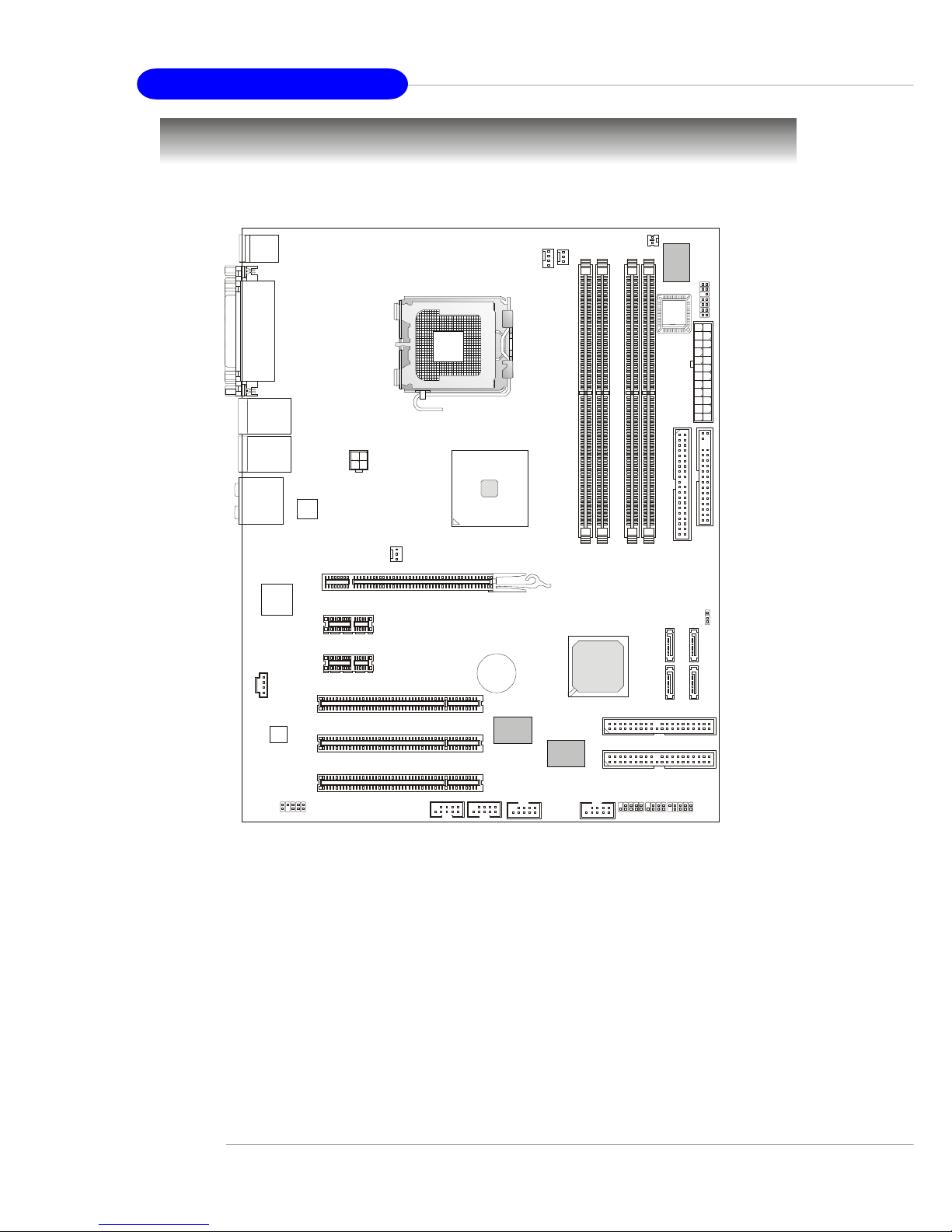
Mainboard Layout
925X Neo Platinum (MS-7053) v1.X ATX Mainboard
NBFAN1
CPUFAN2
JC11
Intel
925X
JPW1
S
A
T
A
2
S
A
T
A
1
S
A
T
A
4
S
A
T
A
3
JCD1
BROADCOM
BCM5751KFB
T:
M:
B:
Line-In
Line-Out
Mic
T:RS-Out
M:CS
B:SPDIF Out
-Out
W
i
n
b
o
n
d
W
8
3
6
2
7
T
H
F
VIA
VT6410
VIA
VT6306
ICH6/
ICH6R
B
A
T
T
+
D
I
M
M
1
D
I
M
M
3
D
I
M
M
4
D
I
M
M
2
A
T
X
1
JLPC1
PCI 3
PCI 2
PCI 1
PCI_E3
PCI _E2
PCI_E1
IDE 2
I
D
E
1
F
D
D
1
IDE 3
JFP1
J
B
A
T
1
JFP2JDB1
JAUD1
JUSB1 JUSB2
J1394_2
(Optoinal)
J1394_3
(Optional)
Top : mouse
Bottom: keyboard
BIOS
T: LAN jack (Optiona l)
B: USB ports
Top : Parallel Port
Bottom:
COM A
1394 port (Optio n al)
SPDIF Out
CMI
9880L
T: LAN jack (Optiona l)
B: USB ports
SYSFAN2
Intel
82562EZ

E-2-1
Hardware Setup
Chapter 2. Hardware Setup
This chapter tells you how to install the CPU, memory modules,
and expansion cards, as well as how to setup the jumpers on the
mainboard. Also, it provides the instructions on connecting the peripheral devices, such as the mouse, keyboard, etc.
While doing the installation, be careful in holding the components and follow the installation procedures.
Hardware Setup
E-2-2
MS-7053 ATX Mainboard
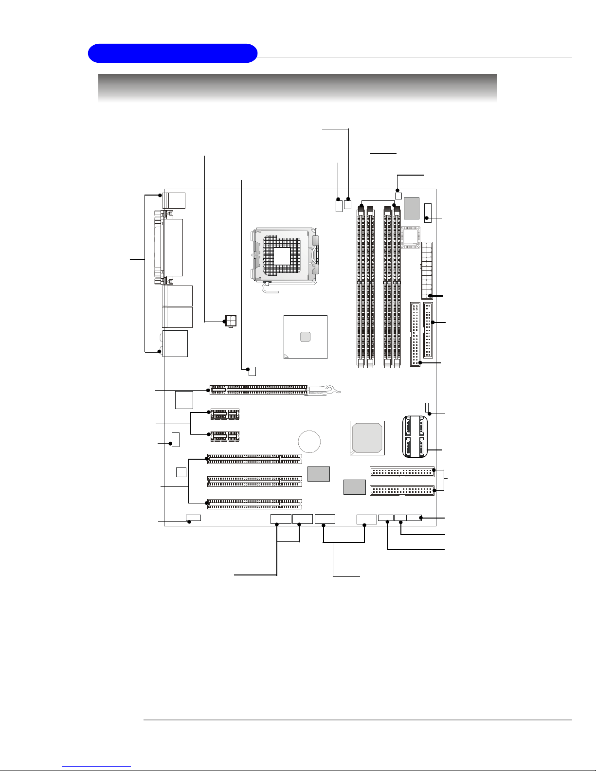
Quick Components Guide
B
A
T
T
+
DDR DIMMs, p.2-7
IDE2, IDE3,
p.2-15
JFP2, p.2-17
Back Panel
I/O, p.2-10
CPUFAN1, p.2-14
ATX1, p.2-9
JFP1, p.2-17
PCI Slots 1~3,
p.2-23
JUSB1, JUSB2, p.2-19
JAUD1, p.2-18
SATA1~SATA4,
p.2-16
JDB1, p.2-21
J1394_2, J1394_3,
p.2-20
JCI1, p.2-20
JLPC1, p.2-19
JBAT1, p.2-22
JPW1, p.2-9
PCI Express x1,
p.2-23
PCI Express x16,
p.2-23
JCD1, p.2-18
NBFAN1, p.2-14
FDD1, p.2-14
IDE1, p.2-15
SYSFAN2, p.2-14

E-2-3
Hardware Setup
Central Processing Unit: CPU
The mainboard supports Intel® Pentium 4 Prescott processor. The mainboard
uses a CPU socket called LGA775. When you are installing the CPU, make sure to
install the cooler to prevent overheating. If you do not have the CPU cooler,
contact your dealer to purchase and install them before turning on the computer.
For the latest information about CPU, please visit http://www.msi.com.tw/
program/products/mainboard/mbd/pro_mbd_cpu_support.php.
MSI Reminds You...
Overheating
Overheating will seriously damage the CPU and system, always make
sure the cooling fan can work properly to protect the CPU from
overheating.
Replacing the CPU
While replacing the CPU, always turn off the ATX power supply or
unplug the power supply’s power cord from grounded outlet first to
ensure the safety of CPU.
Overclocking
This motherboard is designed to support overclocking. However, please
make sure your components are able to tolerate such abnormal setting,
while doing overclocking. Any attempt to operate beyond product specifications is not recommended. We do not guarantee the damages
or risks caused by inadequate operation or beyond product
specifications.
Introduction to LGA 775 CPU
The surface of LGA 775 CPU.
Remember to apply some silicone heat transfer compound on
it for better heat dispersion.
Y ellow triangle is the Pin 1 indicator
The pin-pad side of LGA 775
CPU.
Y ellow triangle is the Pin 1 indicator
Alignment Key Alignment Key

E-2-4
MS-7053 ATX Mainboard
2. Remove the cap from lever hinge
side (as the arrow shows).
1. The CPU has a plastic cap on it to
protect the contact from damage.
Before you install the CPU, always
cover it to protect the socket pin.
3. The pins of socket reveal.
CPU & Cooler Installation
When you are installing the CPU, make sure the CPU has a cooler at-
tached on the top to prevent overheating. If you do not have the cooler, contact
your dealer to purchase and install them before turning on the computer. Meanwhile,
do not forget to apply some silicon heat transfer compound on CPU before installing
the heat sink/cooler fan for better heat dispersion.
Follow the steps below to install the CPU & cooler correctly. Wrong installation
will cause the damage of your CPU & mainboard.
4. Open the load lever.
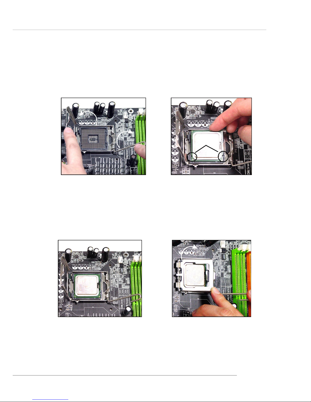
E-2-5
Hardware Setup
6. After confirming the CPU direction
for correct mating, put down the
CPU in the socket housing frame.
Be sure to grasp on the edge of
the CPU base. Note that the alignment keys are matched.
8. Cover the load plate onto the
package.
7. Visually inspect if the CPU is
seated well into the socket. If not,
take out the CPU with pure vertical
motion and reinstall.
alignment
key
5. Lift the load lever up and open the
load plate.
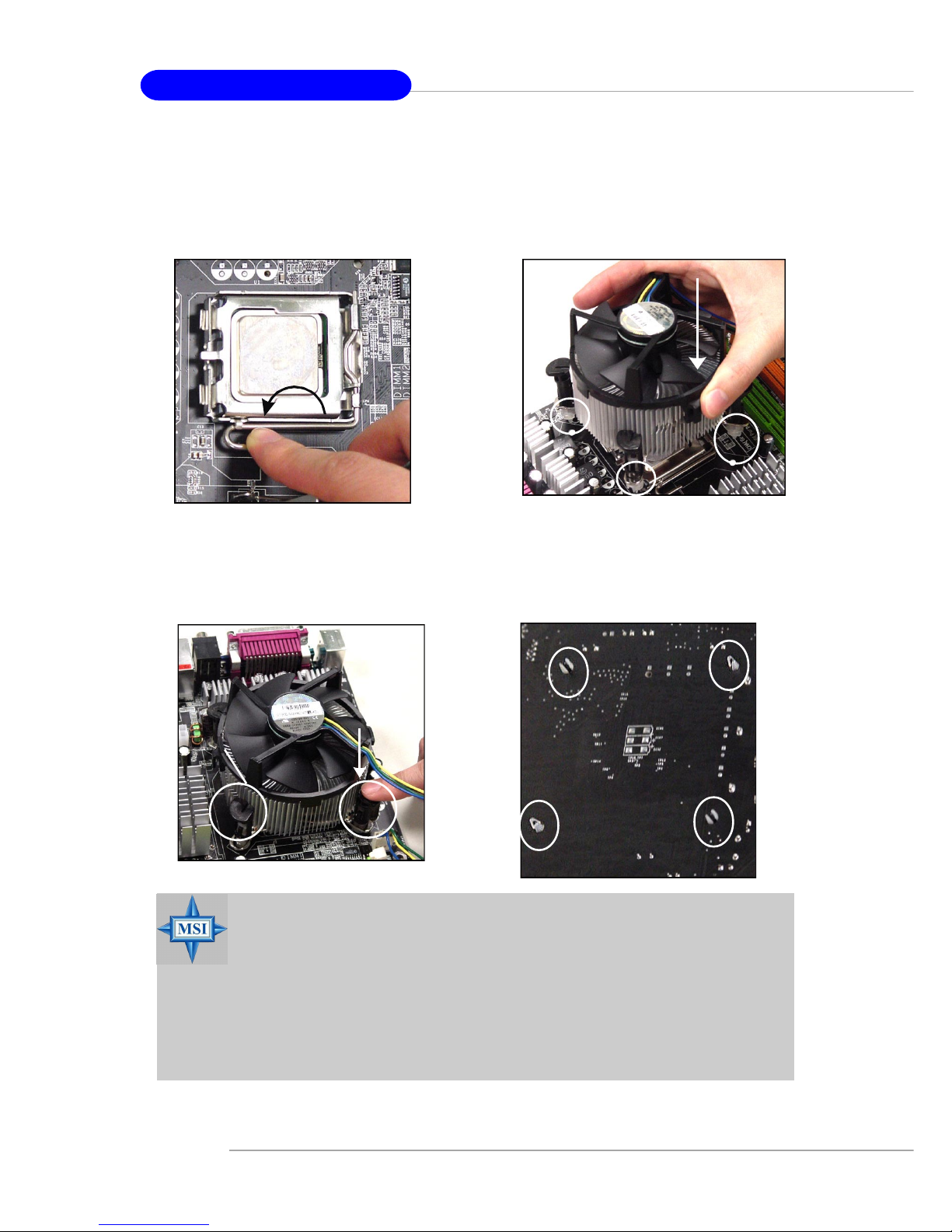
E-2-6
MS-7053 ATX Mainboard
10. Align the holes on the mainboard
with the heatsink. Push down the
cooler until its four clips get
wedged into the holes of the
mainboard.
12.Turn over the mainboard to confirm that the clip-ends are correctly inserted.
11. Press the four hooks down to fasten the cooler. Then rotate the locking switch (refer to the correct direction marked on it) to lock the
hooks.
9. Press down the load lever lightly
onto the load plate, and then secure the lever with the hook under
retention tab.
locking
switch
MSI Reminds You...
1.Confirm if your CPU cooler is firmly installed before turning on your
system.
2.Do not touch the CPU socket pins to avoid damage.
3. Whenever CPU is not installed, always protect your CPU socket pin
with the plastic cap covered (shown in Figure 1) to avoid damage.
4. Please note that the mating/unmating durability of the CPU is 20
cycles. Therefore we suggest you do not plug/unplug the CPU too
often.
E-2-7
Hardware Setup
Memory
The mainboard provides 4 slots for 240-pin DDR2 DIMM, which supports the
memory size up to 4GB.
Since DDR2 modules are not interchangeable with DDR1 and the DDR2 standard is not backward compatible, you should always install DDR2 memory module in
the DDR2 slot (DIMM1~DIMM4). Otherwise, you are not able to boot up your system
and your mainboard might be damaged.
For the updated supporting memory modules, please visit http://www.msi.
com.tw/program/products/mainboard/mbd/pro_mbd_trp_list.php.
DIMM1~DIMM4
(from left to right)
Channel A (DIMM1, DIMM2): Green
Channel B (DIMM3, DIMM4): Orange
Introduction to DDR2 SDRAM
DDR2 is a new technology of memory module, and its speed is the top limit of
current DDR1 technology. DDR2 uses a 1.8V supply for core and I/O voltage, compared to 2.5V for DDR1, and requires 28% less power than DDR1 chips. DDR2 truly
is the future of memory, but will require some changes as the technology is not
backwardly compatible and only motherboards specifically designed for DDR2 memory
will be able to support these chips.
DDR2 incorporates new features at the chip level that give it better signal
integrity, thereby enabling higher clock speeds.
DDR2 modules have 240 pins, versus 184 pins on a DDR1 module, and the
length of DDR2 module is 5.25”. DDR2 modules have smaller and tighter spaced pins.
The height of DDR2 modules varies, but they will typically be less than 1.3” in height.
E-2-8
MS-7053 ATX Mainboard
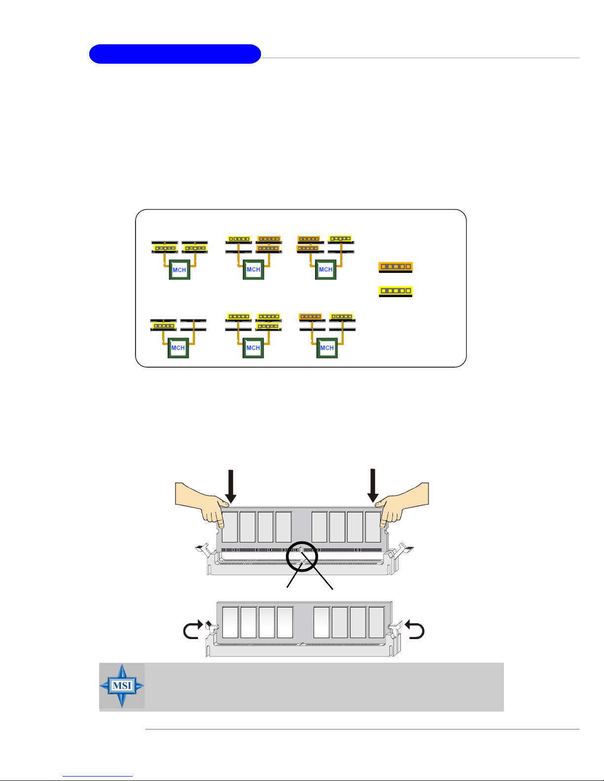
Installing DDR2 Modules
1. The DDR2 DIMM has only one notch on the center of module. The module will
only fit in the right orientation.
2. Insert the DIMM memory module vertically into the DIMM slot. Then push it in
until the golden finger on the memory module is deeply inserted in the socket.
3. The plastic clip at each side of the DIMM slot will automatically close.
Volt
Notch
Memory Module Population Rules
Install at least one DIMM module on the slots. Each DIMM slot supports up to a
maximum size of 1GB. Users can install either single- or double-sided modules to
meet their own needs. Please note that each DIMM can work respectively for
single-channel DDR, while both channels (in different color) populated
with same amount of memory size will work as dual-channel DDR, no matter
how many DIMM modules are populated.
Below are the example of single-channel/dual-channel DDR modes.
MSI Reminds You...
You can barely see the golden finger if the module is properly inserted in the socket.
Dual-channel mode
Single-channel mode
x MB
(ex: 128 MB)
2x MB
(ex: 256 MB)
E-2-9
Hardware Setup
Power Supply
The mainboard supports ATX power supply for the power system. Before
inserting the power supply connector, always make sure that all components are
installed properly to ensure that no damage will be caused.
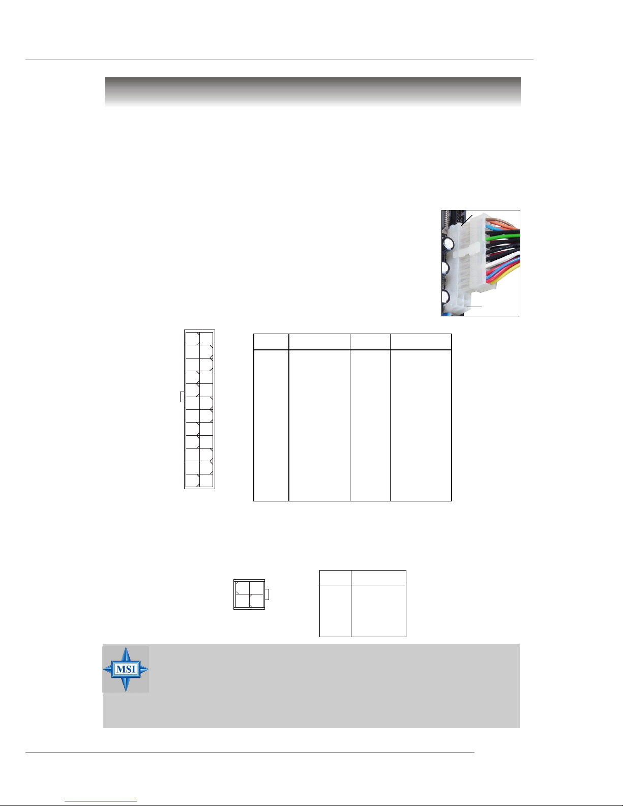
PIN SIGNAL
13 +3.3V
14 -12V
15 GND
1 6 PS-ON#
17 GND
18 GND
19 GND
20 Res
2 1 +5V
2 2 +5V
2 3 +5V
24 GND
PIN SIGNAL
1 +3.3V
2 +3.3V
3 GND
4 +5V
5 GND
6 +5V
7 GND
8 PWR OK
9 5VSB
10 +12V
11 +12V
12 NC
Pin Definition
PIN SIGNAL
1 GND
2 GND
3 12V
4 12V
JPW1 Pin Definition
ATX 12V Power Connector: JPW1
This 12V power connector is used to provide power to the CPU.
ATX 24-Pin Power Connector: ATX 1
This connector allows you to connect an ATX 24-pin power supply. To
connect the ATX 24-pin power supply, make sure the plug of the
power supply is inserted in the proper orientation and the pins are
aligned. Then push down the power supply firmly into the connector.
You may use the 20-pin ATX power supply as you like. If
you’d like to use the 20-pin ATX power supply, please plug your
power supply along with pin 1 & pin 13 (refer to the image at the
right hand). There is also a foolproof design on pin 11, 12, 23 & 24
to avoid wrong installation.
ATX1
1
12
24
13
pin 12
pin 13
MSI Reminds You...
1. These two connectors connect to the ATX power supply and have to
work together to ensure stable operation of the mainboard.
2. Power supply of 350 watts (and above) is highly recommended for
system stability.
3. ATX 12V power connection should be greater than 18A.
JPW1
13
42
E-2-10
MS-7053 ATX Mainboard
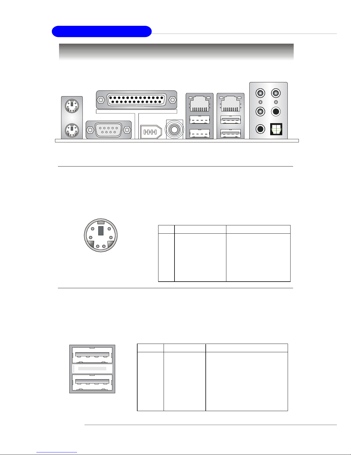
USB Connectors
The mainboard provides an OHCI (Open Host Controller Interface) Universal
Serial Bus root for attaching USB devices such as keyboard, mouse or other USBcompatible devices. You can plug the USB device directly into the connector.
USB Ports
1 2 3 4
5 6 7 8
PIN SIGNAL DESCRIPTION
1 VCC +5V
2 -Data 0 Negative Data Channel 0
3 +Data0 Positive Data Channel 0
4 GND Ground
5 VCC +5V
6 -Data 1 Negative Data Channel 1
7 +Data 1 Positive Data Channel 1
8 GND Ground
USB Port Description
The back panel provides the following connectors:
Back Panel
Mouse/Keyboard Connector
The mainboard provides a standard PS/2® mouse/keyboard mini DIN connector
for attaching a PS/2® mouse/keyboard. You can plug a PS/2® mouse/keyboard directly
into this connector. The connector location and pin assignments are as follows:
Keyboard
COM A
USB Ports
Mic
L-Out
L-In
Mouse
Parallel
Giga LAN
(Optional)
SPDIF
Out
RS-Out
SPDIF Out
CS-Out
10/100 LAN
(Optional)
1394 port
(Optional)
PIN SIGNAL DESCRIPTION
1 Mouse/Keyboard Data Mouse/Keyboard data
2 NC No connection
3 GND Ground
4 VCC +5V
5 Mouse/Keyboard Clock Mouse/Keyboard clock
6 NC No connection
Pin Definition
PS/2 Mouse / Keyboard
(6-pin Female)
2
1
3
4
5
6
E-2-11
Hardware Setup
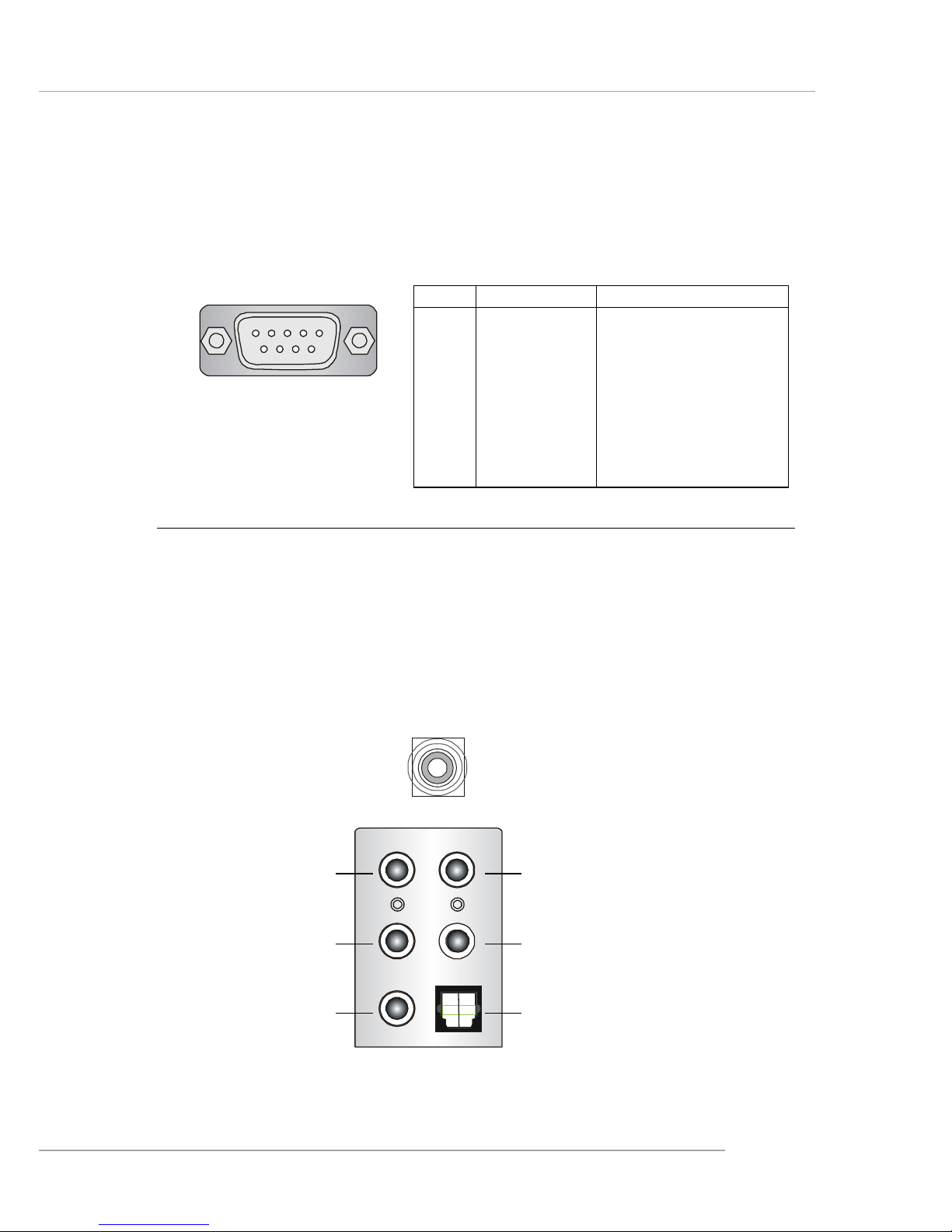
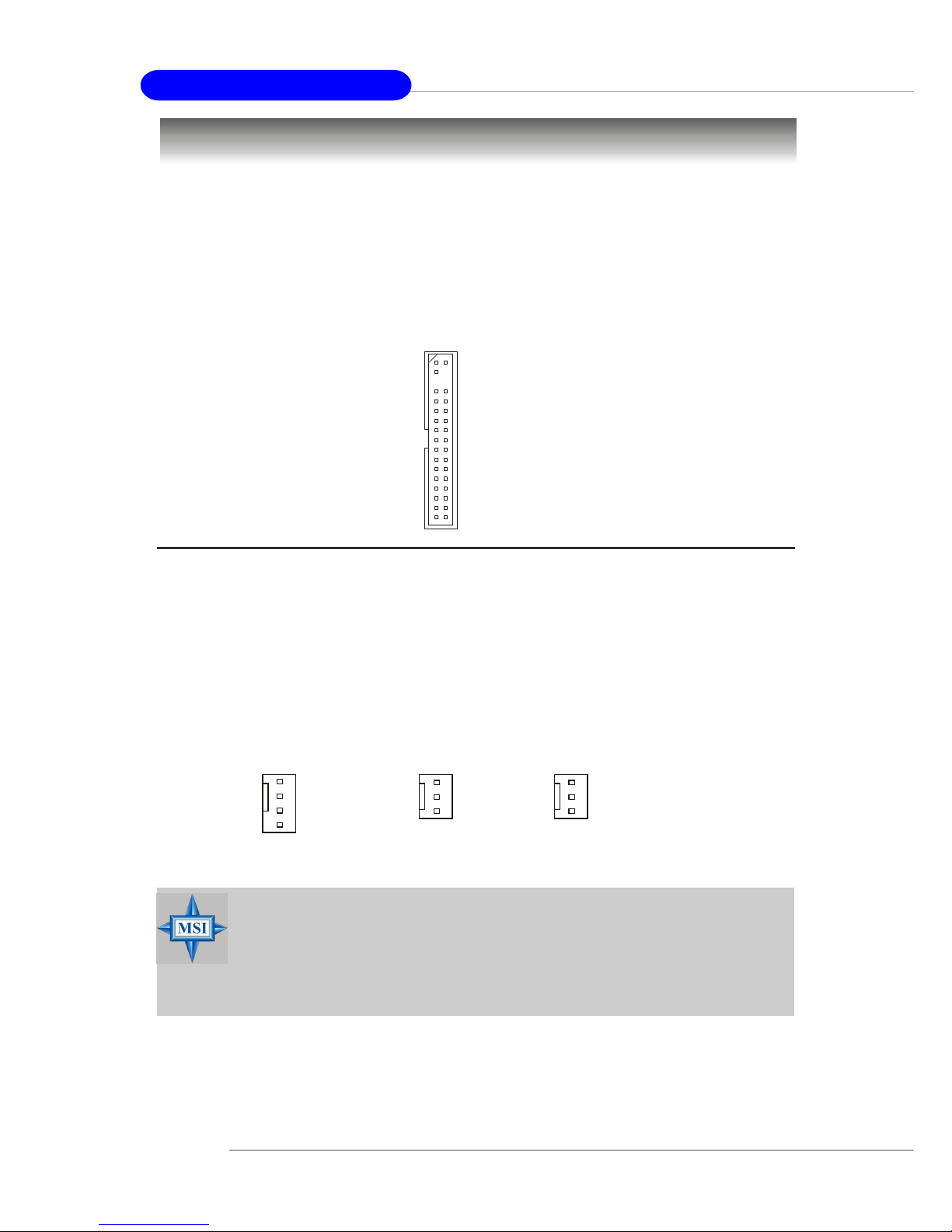
Serial Port Connector
The mainboard offers one 9-pin male DIN connector as the serial port. The port
is a 16550A high speed communication port that sends/receives 16 bytes FIFOs. You
can attach a serial mouse or other serial devices directly to the connector.
PIN SIGNAL DESCRIPTION
1 DCD Data Carry Detect
2 SIN Serial In or Receive Data
3 SOUT Serial Out or Transmit Data
4 DTR Data Terminal Ready)
5 GND Ground
6 DSR Data Set Ready
7 RTS Request T o Send
8 CTS Clear T o Send
9 RI Ring Indicate
Pin Definition
9-Pin Male DIN Connector
1 2 3 4 5
6 7 8 9
Audio Port Connectors
The left 3 audio jacks are for 2-channel mode for stereo speaker output: Line
Out is a connector for Speakers or Headphones. Line In is used for external CD
player, Tape player, or other audio devices. Mic is a connector for microphones.
However, there is an advanced audio application provided by CMI9880L to
offer support for 7.1-channel audio operation and can turn rear audio connectors
from 2-channel to 4-/5.1-channel audio.
S/PDIF Out-Coaxial
Rear Speaker Out
(in 7.1CH / 5.1CH)
Line Out
Line In
MIC
Center/Subwoofer
Speaker Out
( in 7.1CH / 5.1CH)
S/PDIF Out-Optical
(in 7.1CH / 5.1CH)
E-2-12
MS-7053 ATX Mainboard
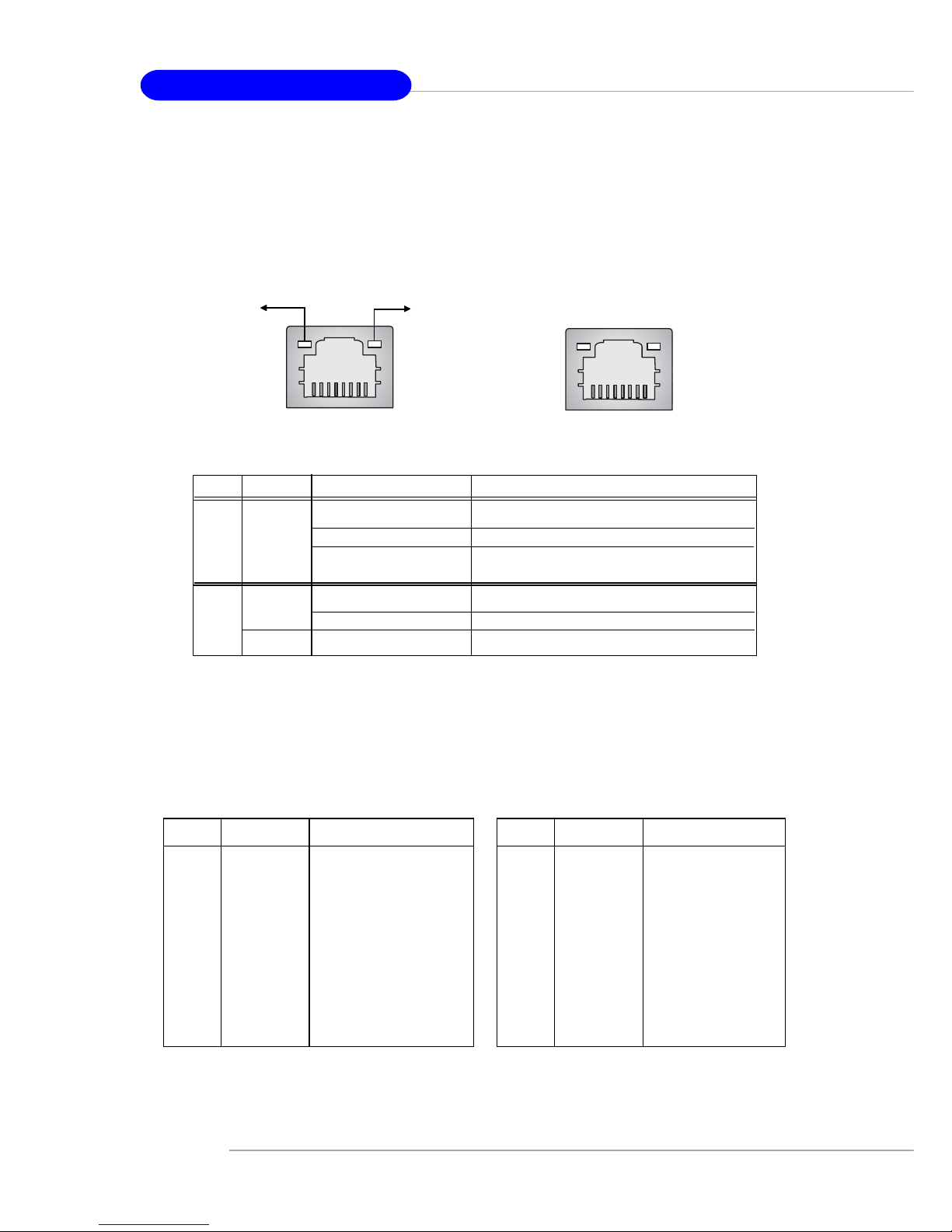
RJ-45 LAN Jack: 10/100 LAN (Intel 82562) / Giga-bit LAN (Broadcom
PCI-E) (Optional)
The mainboard provides two standard RJ-45 jacks for connection to Local
Area Network (LAN). Giga-bit LAN enables data to be transferred at 1000, 100 or
10Mbps. You can connect a network cable to either LAN jack.
The pin assignments vary depending on the transfer rates: 10/100Mbps or
1000Mbps. Note that Pin 1/2, 3/6, 4/5, 7/8 must work in pairs. Please refer
to the following for details:
LED Color LED State Condition
Off LAN link is not established.
Left Orange On (steady state) LAN link is established.
On (brighter & pulsing) The computer is communicating with another
computer on the LAN.
Green Off 10 Mbit/sec data rate is selected.
Right On 100 Mbit/sec data rate is selected.
Orange On 1000 Mbit/sec data rate is selected.
Link Indicator
8 1
Activity Indicator
RJ-45 10/100 LAN Jack
8 1
RJ-45 Giga-bit LAN Jack
10/100 LAN Pin Definition Giga-bit LAN Pin Definition
PIN SIGNAL DESCRIPTION
1 D0P Differential Pair 0+
2 D0N Differential Pair 0 3 D1P Differential Pair 1+
4 D2P Differential Pair 2+
5 D2N Differential Pair 2 6 D1N Differential Pair 1 7 D3P Differential Pair 3+
8 D3N Differential Pair 3-
PIN SIGNAL DESCRIPTION
1 TD P Transmit Differential Pair
2 TDN Transmit Differential Pair
3 RDP Receive Differential Pair
4 NC Not Used
5 NC Not Used
6 RDN Receive Differential Pair
7 NC Not Used
8 NC Not Used
E-2-13
Hardware Setup
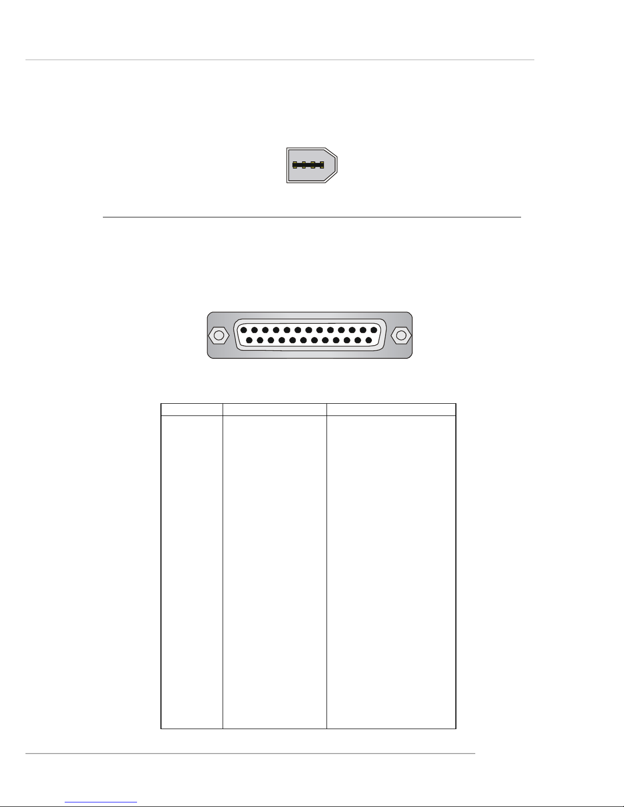
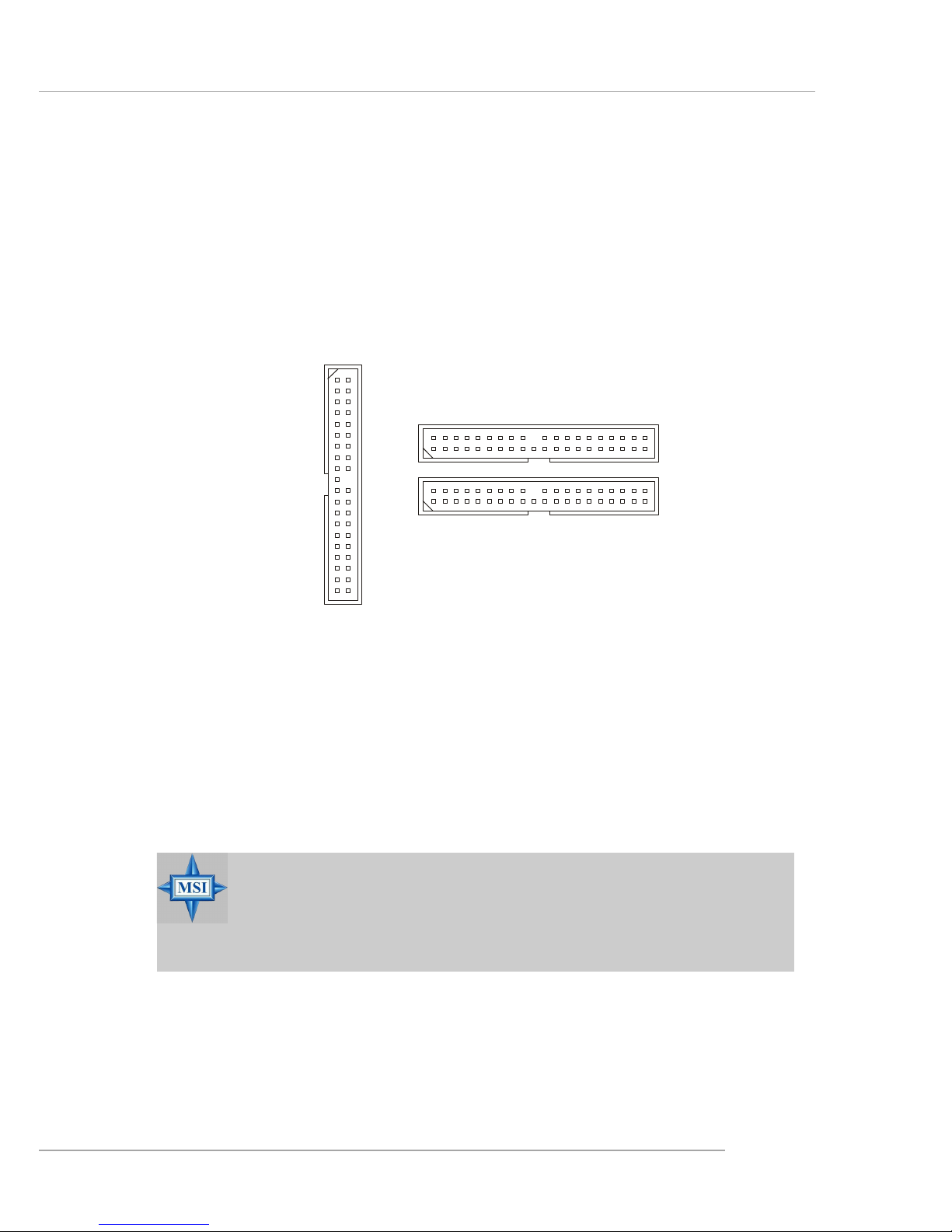
Parallel Port Connector: LPT1
The mainboard provides a 25-pin female centronic connector as LPT. A parallel
port is a standard printer port that supports Enhanced Parallel Port (EPP) and Extended Capabilities Parallel Port (ECP) mode.
PIN SIGNAL DESCRIPTION
1 STROBE Strobe
2 DATA0 Data0
3 DATA1 Data1
4 DATA2 Data2
5 DATA3 Data3
6 DATA4 Data4
7 DATA5 Data5
8 DATA6 Data6
9 DATA7 Data7
10 ACK# Acknowledge
11 BUSY Busy
12 PE Paper End
1 3 SELECT Select
1 4 AUTO FEED# Automatic Feed
15 ERR# Error
1 6 INIT# Initialize Printer
17 SLIN# Select In
18 GND Ground
19 GND Ground
20 GND Ground
21 GND Ground
22 GND Ground
23 GND Ground
24 GND Ground
25 GND Ground
Pin Definition
13 1
14
25
1394 Port (Optional)
There is one 1394 port on the back panel providing the connection for 1394
devices.
1394 port
E-2-14
MS-7053 ATX Mainboard
The mainboard provides connectors to connect to FDD, IDE HDD, case, LAN,
USB Ports and CPU/System FAN.
Floppy Disk Drive Connector: FDD1
The mainboard provides a standard floppy disk drive connector that supports
360K, 720K, 1.2M, 1.44M and 2.88M floppy disk types.
Connectors
FDD1
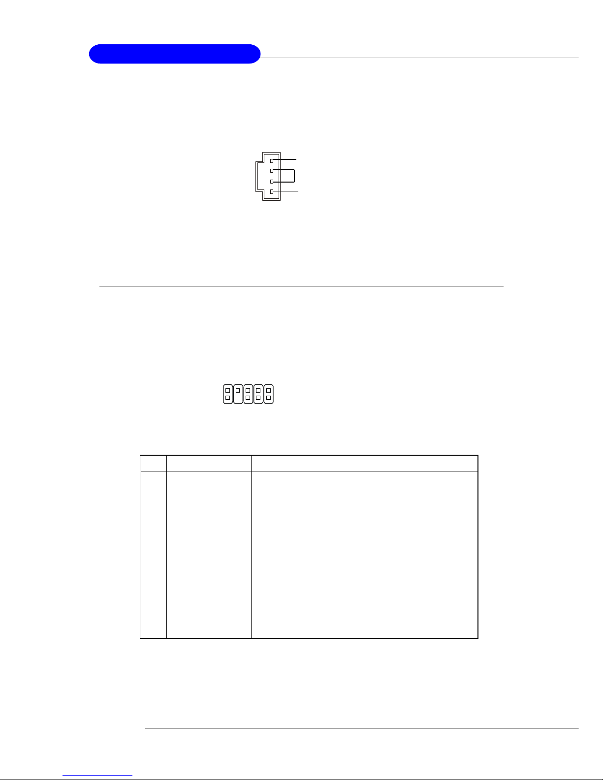
Fan Power Connectors: CPUF AN2/SYSFAN2/NBF AN1
The CPUFAN2 (processor fan), SYSFAN2 (system fan) and NBFAN1
(NorthBridge Chipset fan) support system cooling fan with +12V. It supports four/
three-pin head connector. When connecting the wire to the connectors, always take
note that the red wire is the positive and should be connected to the +12V, the black
wire is Ground and should be connected to GND. If the mainboard has a System
Hardware Monitor chipset on-board, you must use a specially designed fan with
speed sensor to take advantage of the CPU fan control.
NBFAN1
+12V
GND
NC
CPUFAN2
SENSOR
+12V
GND
Control
SYSFAN2
Sensor
+12V
GND
MSI Reminds You...
1. Always consult the vendors for proper CPU cooling fan.
2. CPUFAN2 supports fan control. CPU fan with 3 or 4 pins are both
available.
3. Please refer to the recommended CPU fans at Intel® official
website.
E-2-15
Hardware Setup
Hard Disk Connectors: IDE1, IDE2 & IDE3 (IDE 2 & IDE3 are optional)
The mainboard has one 32-bit Ultra DMA 66/100 IDE controller integrated in
ICH6/ICH6R, which supports PIO & Bus Master operation modes and it can connect
up to two Ultra ATA drives.
There is also another Ultra DMA 66/100/133 IDE controller integrated in the
optional VIA 6410 IDE Raid Controller, which supports RAID 0 & RAID 1, and can
connect up to four Ultra ATA 133 drives.
IDE1 (Primary IDE Connector)
The first hard drive should always be connected to IDE1. IDE1 can connect a Master
and a Slave drive. You must configure second hard drive to Slave mode by setting the
jumper accordingly.
IDE2, IDE3 (Third and Secondary IDE Connector)
IDE2 & IDE3 can also connect a Slave and a Master drive.
MSI Reminds You...
If you install two hard disks on cable, you must configure the second
drive to Slave mode by setting its jumper. Refer to the hard disk
documentation supplied by hard disk vendors for jumper setting
instructions.
IDE2 (yellow)
IDE3 (yellow)
IDE1 (blue)
E-2-16
MS-7053 ATX Mainboard
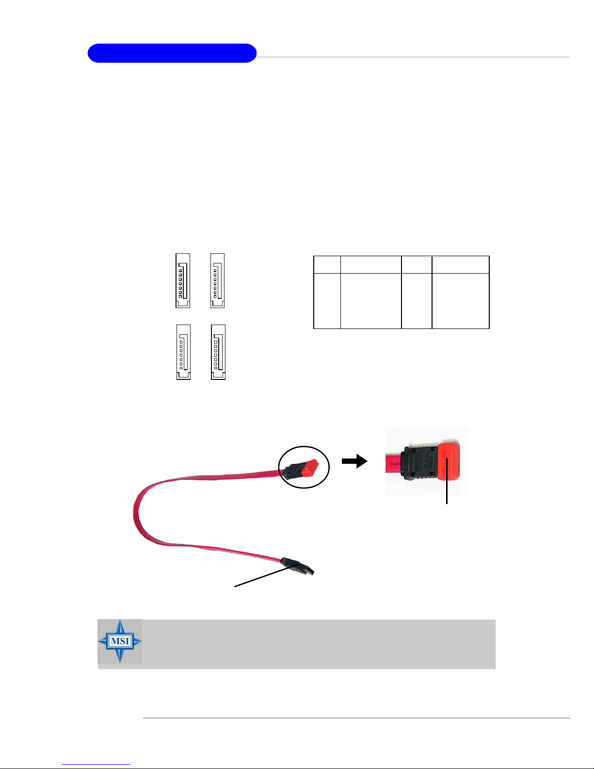
Serial ATA/Serial ATA RAID Connectors controlled by Intel ICH6/
ICH6R: SA TA1~SA T A4
The SouthBridge of this mainboard is Intel ICH6/ICH6R which supports four
serial ATA connectors SATA1~SATA4.
SATA1~SATA4 are dual high-speed Serial ATA interface ports. Each supports
1st generation serial ATA data rates of 150 MB/s. Both connectors are fully compliant
with Serial ATA 1.0 specifications. Each Serial ATA connector can connect to 1 hard
disk device.
PIN SIGNAL PIN SIGNAL
1 GND 2 TXP
3 TXN 4 GND
5 RXN 6 RXP
7 GND
SA TA1~ SA T A4 Pin Definition
MSI Reminds You...
Please do not fold the serial ATA cable in a 90-degree angle, since
this might cause the loss of data during transmission.
Connect to serial ATA ports
Take out the dust cover and
connect to the hard disk
devices
Serial A TA cable
SATA4
SATA3
1
7
SATA2
SATA1
1
7
E-2-17
Hardware Setup
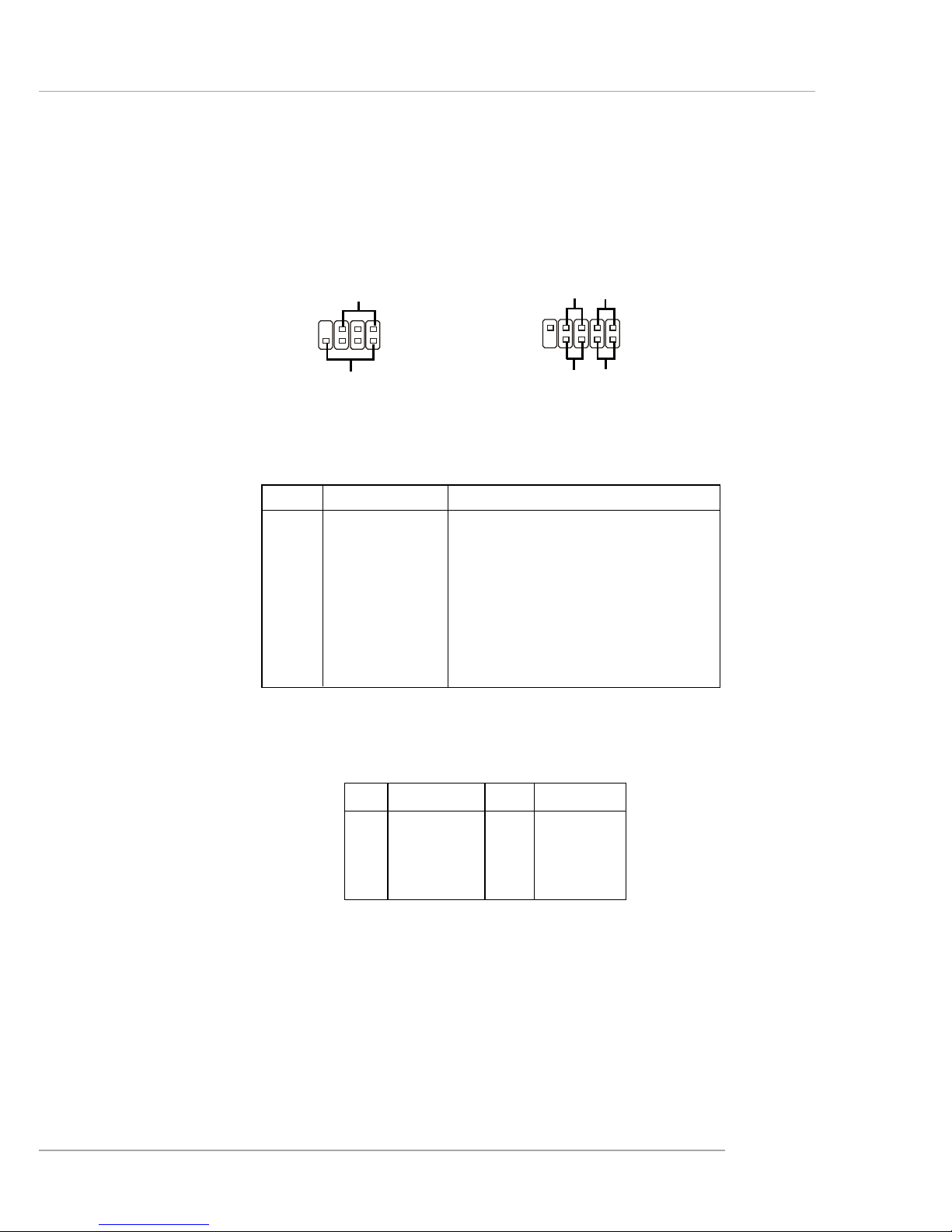
Front Panel Connectors: JFP1 & JFP2
The mainboard provides two front panel connectors for electrical connection
to the front panel switches and LEDs. JFP2 is compliant with Intel® Front Panel I/O
Connectivity Design Guide.
PIN SIGNAL DESCRIPTION
1 HD_LED_P Hard disk LED pull-up
2 FP PWR/SLP MSG LED pull-up
3 HD_LED_N Hard disk active LED
4 FP PWR/SLP MSG LED pull-up
5 RST_SW_N Reset Switch low reference pull-down to GND
6 PWR_SW_P Power Switch high reference pull-up
7 RST_SW_P Reset Switch high reference pull-up
8 PWR_SW_N Power Switch low reference pull-down to GND
9 RSVD_DNU Reserved. Do not use.
JFP2 Pin Definition
PIN SIGNAL PIN SIGNAL
1 GND 2 SPK3 SLED 4 BUZ+
5 PLED 6 BUZ7 NC 8 SPK+
JFP1 Pin Definition
1
2
9
10
JFP1
HDD
LED
Reset
Switch
Power
LED
Power
Switch
7
8
Power LED
Speaker
1
2
JFP2
E-2-18
MS-7053 ATX Mainboard
Front Panel Audio Connector: JAUD1
The JAUD1 front panel audio connector allows you to connect to the front
panel audio and is compliant with Intel® Front Panel I/O Connectivity Design Guide.
CD-In Connector: JCD1
The connector is for CD-ROM audio connector.
JAUD1
1
2
9
10
JCD1
GND
R
L
PIN SIGNAL DESCRIPTION
1 PORT 1L Analog Port 1 - Left channel
2 GND Ground
3 PORT 1R Analog Port 1 - Right channel
4 PRESENCE# Active low signal - signals BIOS that a High Definition Audio
dongle is connected to the analog header. PRESENCE# = 0
when a High Definition Audio dongle is connected.
5 PORT 2R Analog Port 2 - Right channel
6 SENSE1_RETIRN Jack detection return from front panel JACK1
7 SENSE_SEND Jack detection sense line from the High Definition Audio CODEC
jack detection resistor network
8 KEY Connector Key
9 PORT 2L Analog Port 2 - Left channel
1 0 SENSE2_RETIRN Jack detection return from front panel JACK2
JAUD1 Pin Definition
E-2-19
Hardware Setup
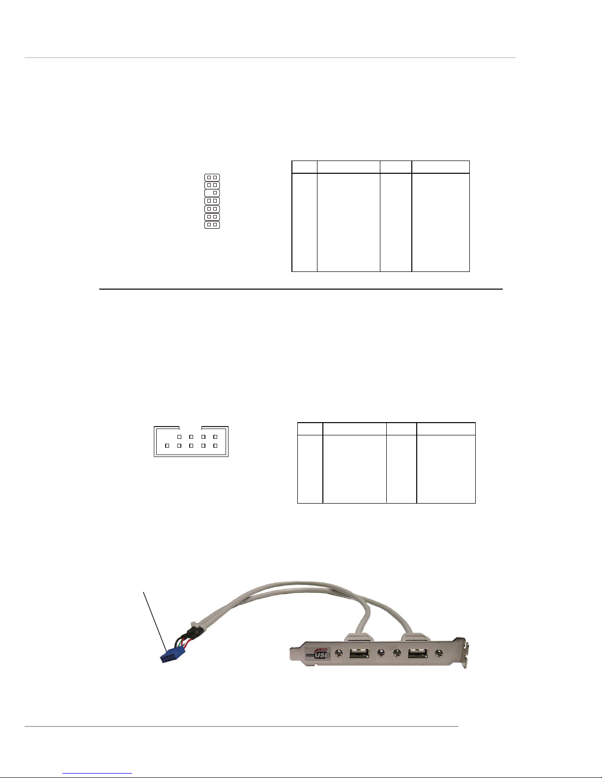
Connected to JUSB1
or JUSB2
USB 2.0 Bracket
(Optional)
Front USB Connectors: JUSB1 & JUSB2
The mainboard provides two standard USB 2.0 pin headers JUSB1 & JUSB2 .
USB 2.0 technology increases data transfer rate up to a maximum throughput of
480Mbps, which is 40 times faster than USB 1.1, and is ideal for connecting highspeed USB interface peripherals such as USB HDD, digital cameras, MP3 players,
printers, modems and the like.
JLPC1 Pin Definition
PIN SIGNAL PIN SIGNAL
1 LCLK 2 Key (no pin)
3 LRST# 4 VCC3
5 LAD0 6 FID0_LRST
7 LAD1 8 VCC5
9 LAD2 10 Key (no pin)
11 LAD3 12 GND
13 LFRAME# 14 GND
PIN SIGNAL PIN SIGNAL
1 VCC 2 VCC
3 USB0- 4 USB15 USB0+ 6 USB1+
7 GND 8 GND
9 Key (no pin) 10 USBOC
JUSB1 & JUSB2 Pin Definition
JUSB1, JUSB2
(USB 2.0)
1
2 10
9
FWH/LPC Debugging Pin Header: JLPC1
The pin header is for internal debugging only.
JLPC1
13
14
2
1
 Loading...