

MSI K7N2GM2-ILSR, K7N2GM2-LSR, MS-7051G, K7N2GM2, K7N2M2 User Manual
i
G52-M7051G1
MS-7051G (v1.X) M-ATX Mainboard
K7N2GM2 / K7N2M2 Series
ii
Manual Rev: 1.0
Release Date: June 2004
FCC-B Radio Frequency Interference Statement
This equipment has been tested and found to comply with the limits for a class B
digital device, pursuant to part 15 of the FCC rules. These limits are designed to
provide reasonable protection against harmful interference when the equipment is
operated in a commercial environment. This equipment generates, uses and can
radiate radio frequency energy and, if not installed and used in accordance with the
instruction manual, may cause harmful interference to radio communications. Operation
of this equipment in a residential area is likely to cause harmful interference, in which
case the user will be required to correct the interference at his own expense.
Notice 1
The changes or modifications not expressly approved by the party responsible for
compliance could void the user’s authority to operate the equipment.
Notice 2
Shielded interface cables and A.C. power cord, if any, must be used in order to
comply with the emission limits.
VOIR LA NOTICE D’INSTALLATION A VANT DE RACCORDER AU RESEAU.
Micro-Star International
MS-7051G
This device complies with Part 15 of the FCC Rules. Operation is subject to the
following two conditions:
(1) this device may not cause harmful interference, and
(2) this device must accept any interference received, including interference that
may cause undesired operation

iii
Copyright Notice
The material in this document is the intellectual property of MICRO-STAR
INTERNATIONAL. We take every care in the preparation of this document, but no
guarantee is given as to the correctness of its contents. Our products are under
continual improvement and we reserve the right to make changes without notice.
Trademarks
All trademarks are the properties of their respective owners.
AMD, Athlon™, Athlon™ XP, Thoroughbred™, and Duron™ are registered
trademarks of AMD Corporation.
Intel® and Pentium® are registered trademarks of Intel Corporation.
PS/2 and OS®/2 are registered trademarks of International Business Machines
Corporation.
Microsoft is a registered trademark of Microsoft Corporation. Windows® 98/2000/NT/
XP are registered trademarks of Microsoft Corporation.
NVIDIA, the NVIDIA logo, DualNet, and nForce are registered trademarks or trademarks of NVIDIA Corporation in the United States and/or other countries.
Netware® is a registered trademark of Novell, Inc.
Award® is a registered trademark of Phoenix Technologies Ltd.
AMI® is a registered trademark of American Megatrends Inc.
Kensington and MicroSaver are registered trademarks of the Kensington Technology
Group.
PCMCIA and CardBus are registered trademarks of the Personal Computer Memory
Card International Association.
Revision History
Revision Revision History Date
V1.0 First release for PCB 1.X June 2004
with nVidia nForce2 SPP/IGP
and nForce2 MCP RAID

iv
1. Always read the safety instructions carefully.
2. Keep this User’s Manual for future reference.
3. Keep this equipment away from humidity.
4. Lay this equipment on a reliable flat surface before setting it up.
5. The openings on the enclosure are for air convection hence protects the equipment from overheating. Do not cover the openings.
6. Make sure the voltage of the power source and adjust properly 110/220V before connecting the equipment to the power inlet.
7. Place the power cord such a way that people can not step on it. Do not place
anything over the power cord.
8. Always Unplug the Power Cord before inserting any add-on card or module.
9. All cautions and warnings on the equipment should be noted.
10. Never pour any liquid into the opening that could damage or cause electrical
shock.
11. If any of the following situations arises, get the equipment checked by a service
personnel:
! The power cord or plug is damaged.
! Liquid has penetrated into the equipment.
! The equipment has been exposed to moisture.
! The equipment has not work well or you can not get it work according to
User’s Manual.
! The equipment has dropped and damaged.
! The equipment has obvious sign of breakage.
12. Do not leave this equipment in an environment unconditioned, storage
temperature above 600 C (1400F), it may damage the equipment.
Safety Instructions
CAUTION: Danger of explosion if battery is incorrectly replaced.
Replace only with the same or equivalent type recommended by the
manufacturer.
Technical Support
If a problem arises with your system and no solution can be obtained from the user’s
manual, please contact your place of purchase or local distributor. Alternatively,
please try the following help resources for further guidance.
! Visit the MSI homepage & FAQ site for technical guide, BIOS updates, driver
updates, and other information: http://www.msi.com.tw & http://www.msi.
com.tw/program/service/faq/faq/esc_faq_list.php
! Contact our technical staff at: support@msi.com.tw

v
CONTENTS
FCC-B Radio Frequency Interference Statement ........................................................ ii
Copyright Notice ........................................................................................................... iii
Revision History............................................................................................................ iii
Technical Support ........................................................................................................ iv
Safety Instructions ...................................................................................................... iv
Chapter 1. Getting Started ................................................................................... 1-1
Mainboard Specifications .................................................................................. 1-2
Mainboard Layout ..............................................................................................1-5
Packing Contents ............................................................................................... 1-6
Chapter 2. Hardware Setup .................................................................................2-1
Quick Components Guide .................................................................................. 2-2
Central Processing Unit: CPU ............................................................................2-3
CPU Installation Procedures for Socket 462.............................................2-4
Installing AMD Athlon CPU Cooler Set........................................................ 2-5
Memory ............................................................................................................... 2-6
Introduction to DDR SDRAM....................................................................... 2-6
DIMM Module Combination .......................................................................... 2-7
Installing DDR Modules ............................................................................... 2-7
Power Supply..................................................................................................... 2-8
ATX 20-Pin Power Connector: JWR1 ........................................................2-8
ATX 12V Power Connector: JPW1............................................................ 2-8
Back Panel .......................................................................................................... 2-9
Mouse Connector .......................................................................................2-9
Keyboard Connector................................................................................2-10
VGA Connector ........................................................................................2-10
Serial Port Connector ............................................................................... 2-11
USB Connectors ....................................................................................... 2-11
IEEE 1394 Port........................................................................................... 2-11
LAN (RJ-45) Jack .....................................................................................2-12
Audio Port Connectors.............................................................................2-12
Parallel Port Connector: LPT1 ..................................................................2-13
Connectors ....................................................................................................... 2-14
Floppy Disk Drive Connector: FDD1 ........................................................2-14
Fan Power Connectors: CPU_FAN1/SYS_FAN1 ....................................2-14
Hard Disk Connectors: IDE1 & IDE2.........................................................2-15
Serial ATA HDD Connectors: SATA1&SATA2.........................................2-16
Aux Line-In Connector: AUX_IN1 ............................................................2-16

vi
Front Panel Connectors: JFP1 & JFP2.....................................................2-17
CD-In Connector: JCD1 ............................................................................2-18
Front Panel Audio Connector: JAUD1 .....................................................2-18
Chassis Intrusion Switch Connector: JCI1 .............................................2-19
Front USB Connectors: JUSB1 & JUSB2 ................................................ 2-19
Serial Port Connector: JCOM2 .................................................................2-19
IEEE 1394 Connectors: J1394_1 .............................................................2-20
TV-Out Connector: JTV1..........................................................................2-21
SPDIF Connector: JSP1 ............................................................................ 2-22
Jumpers ............................................................................................................2-23
Clear CMOS Jumper: JBA T1 ....................................................................2-23
Slots ..................................................................................................................2-24
AGP (Accelerated Graphics Port) Slot ...................................................2-24
PCI (Peripheral Component Interconnect) Slots......................................2-24
CNR Slot ....................................................................................................2-24
PCI Interrupt Request Routing..................................................................2-24
Chapter 3. BIOS Setup........................................................................................... 3-1
Entering Setup .................................................................................................... 3-2
Control Keys ............................................................................................... 3-2
Getting Help ................................................................................................ 3-2
The Main Menu ................................................................................................... 3-3
Standard CMOS Features.................................................................................. 3-5
Advanced BIOS Features.................................................................................. 3-7
Advanced Chipset Features ...........................................................................3-10
Integrated Peripherals...................................................................................... 3-12
Power Management Setup ..............................................................................3-17
PNP/PCI Configurations ....................................................................................3-20
H/W Monitor ......................................................................................................3-22
Cell Menu ..........................................................................................................3-23
Load Fail-Safe/Optimized Defaults .................................................................3-27
Set Supervisor/User Password...................................................................... 3-28
Chapter 4. Introduction to DigiCell .................................................................... 4-1
Main ..................................................................................................................... 4-2
Communication ................................................................................................... 4-4
Software Access Point ..................................................................................... 4-5
Terminology ................................................................................................. 4-5
Access Point Mode ....................................................................................4-6
WLAN Card Mode .......................................................................................4-7

vii
Live Update......................................................................................................... 4-8
MEGA STICK ....................................................................................................... 4-9
Basic Function ............................................................................................ 4-9
Non-Unicode programs supported .......................................................... 4-11
Audio Speaker Setting .....................................................................................4-13
Power on Agent ...............................................................................................4-15
Power On ..................................................................................................4-15
Power Off / Restart .................................................................................. 4-16
Start With ..................................................................................................4-16
Auto Login.................................................................................................4-17
Chapter 5. nVIDIA RAID Introduction ................................................................. 5-1
Introduction.................................................................................................................5-2
System Requirement .......................................................................................... 5-2
RAID Arrays........................................................................................................ 5-2
Summary of RAID Configurations ..................................................................... 5-2
RAID Configuration .................................................................................................... 5-3
Basic Configuration Instructions ....................................................................... 5-3
Setting Up the NVRAID BIOS .............................................................................5-3
NVIDIA RAID Untility Installation................................................................................. 5-7
Installing the NVIDIA RAID Software Under Windows
(for Non-bootable RAID Array) ..................................................... 5-7
Installing the RAID Driver (for bootable RAID Array) .......................................5-8
Initializing and Using the Disk Array ................................................................5-10
RAID Drives Management........................................................................................5-12
Viewing RAID Array Configurations ...............................................................5-12
Setting Up a Spare RAID Disk..........................................................................5-14
Rebuilding a RAID Mirrored Array ................................................................... 5-20

1-1
Getting Started
Chapter 1. Getting
Started
Thank you for purchasing the K7N2GM2/K7N2M2 (MS-7051G
v1.X) Micro ATX mainboard. The K7N2GM2/K7N2M2 mainboard is
based on NVIDIA® nForce™2 SPP/IGP & NVIDIA® nForce™2 MCP
RAID for optimal system efficiency. Designed to fit the advanced
AMD® Athlon™, Athlon™ XP or Duron™ processors, the K7N2GM2/
K7N2M2 mainboard delivers a high performance and professional
desktop platform solution.
Getting Started

1-2
MS-7051G M-ATX Mainboard
Mainboard Specifications
CPU
! Supports Socket A (Socket-462) for AMD Athlon/Athlon XP/Duron processors
! Supports FSB 400 Athlon XP processor from 1100 MHz up to 3200+ or above
(For the latest information about CPU, please visit http://www.msi.com.tw/program/
products/mainboard/mbd/pro_mbd_cpu_support.php)
Chipset
! NVIDIA® nForce2 SPP/nForce2 IGP
- FSB @266/333/400 MHz
- AGP 8X and PCI Advanced high performance memory controller
- Supports AGP 3.0 8x interface
- Integrated graphics controller (for nForce2 IGP only)
! NVIDIA nForce2 MCP RAID
- Integrated Faster Ethernet MAC
- Integrated Hardware Sound Blaster/Direct Sound AC97 audio
- Ultra DMA 66/100/133 master mode PCI EIDE controller
- Supports USB 2.0
- Integrated SATA Interface
Main Memory
! Supports two 64-bit wide DDR data channels
! Supports a maximum memory size up to 2GB
! Supports DDR 333 (for nForce2 IGP)/400 (for nForce2 SPP) memory module.
(For the updated supporting memory modules, please visit http://www.msi.com.tw/
program/products/mainboard/mbd/pro_mbd_trp_list.php.)
Slots
! One AGP (Accelerated Graphics Port) slot supports 8x/4x
! Three PCI 2.2 32-bit Master PCI Bus slots.
! Supports 3.3V/5V PCI bus Interface
USB Interface
! 8 USB ports
- Controlled by nForce2 MCP RAID southbridge
- 4 ports in the rear I/O, 4 ports via external bracket
On-Board IDE
! Two IDE controllers integrated on the nVIDIA nForce2 MCP RAID chipset providing
IDE HDD/CD-ROM with PIO, Bus Master and Ultra DMA66/100/133 operation modes
! Can connect up to four IDE devices
1-3
Getting Started
On-Board Peripherals
! On-Board Peripherals include:
- 1 floppy port supports 1 FDD with 360K, 720K, 1.2M, 1.44M and 2.88Mbytes
- 2 serial ports/1VGA port
- 1 parallel port supports SPP/EPP/ECP mode
- audio ports in vertical
LAN
! Realtek 8201CL LAN PHY
- Supports 10/100Mb/s auto-negotiation operation
On-Board 1394 (optional)
! VIA VT6307
Audio
! 5.1 channels S/W audio codec Realtek ALC655 codec
- Compliance with AC97 2.3 Spec
- Meets PC2001 audio performance requirement
SATA Interface
! Integrated SATA Phy, supporting up to 2 ports
! One SATA controller, supporting two drives in master mode
A TTENTION!!!
Please note that users cannot install OS, either WinME or Win98, in
their SATA hard drive. Under these two OSs, SATA can only be
used as a normal storage device.

1-4
MS-7051G M-ATX Mainboard
NV RAID (Software)
! Supports 2 serial ATA plus 4 parallel ATA
- RAID 1, or 1, 0+1, JBOD is supported
- Booting from RAID
- Cross controller RAID support
- Rebuilding on the Fly
- Spare Disk Allocation
! Supports Windows 2000 and later versions
BIOS
! The mainboard BIOS provides “Plug & Play” BIOS which detects the peripheral
devices and expansion cards of the board automatically.
! The mainboard provides a Desktop Management Interface (DMI) function which
records your mainboard specifications.
Dimension
! Micro-ATX Form Factor: 24.4 cm (L) x 24.4 cm (W)
Mounting
! 8 mounting holes
Others
! Suspend to RAM/Disk (S3/S4)
A TTENTION!!!
To create a bootable RAID volume for a Windows 2000 environment,
Microsoft’s Windows 2000 Service Pack 4 (SP4) is required. As
the end user cannot boot without SP4, a combination installation
CD must be created before attempting to install the operating system onto the bootable RAID volume.
To create the combination installation CD, please refer to the following website:
http://www.microsoft.com/windows2000/
downloads/servicepacks/sp4/HFdeploy.htm
1-5
Getting Started
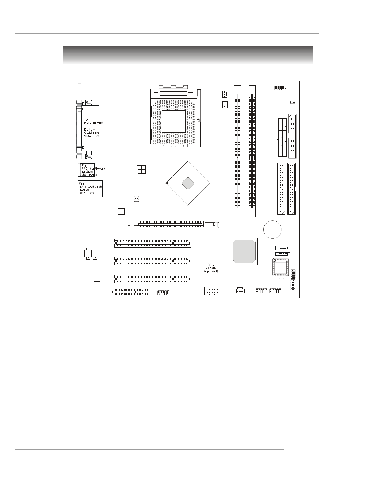
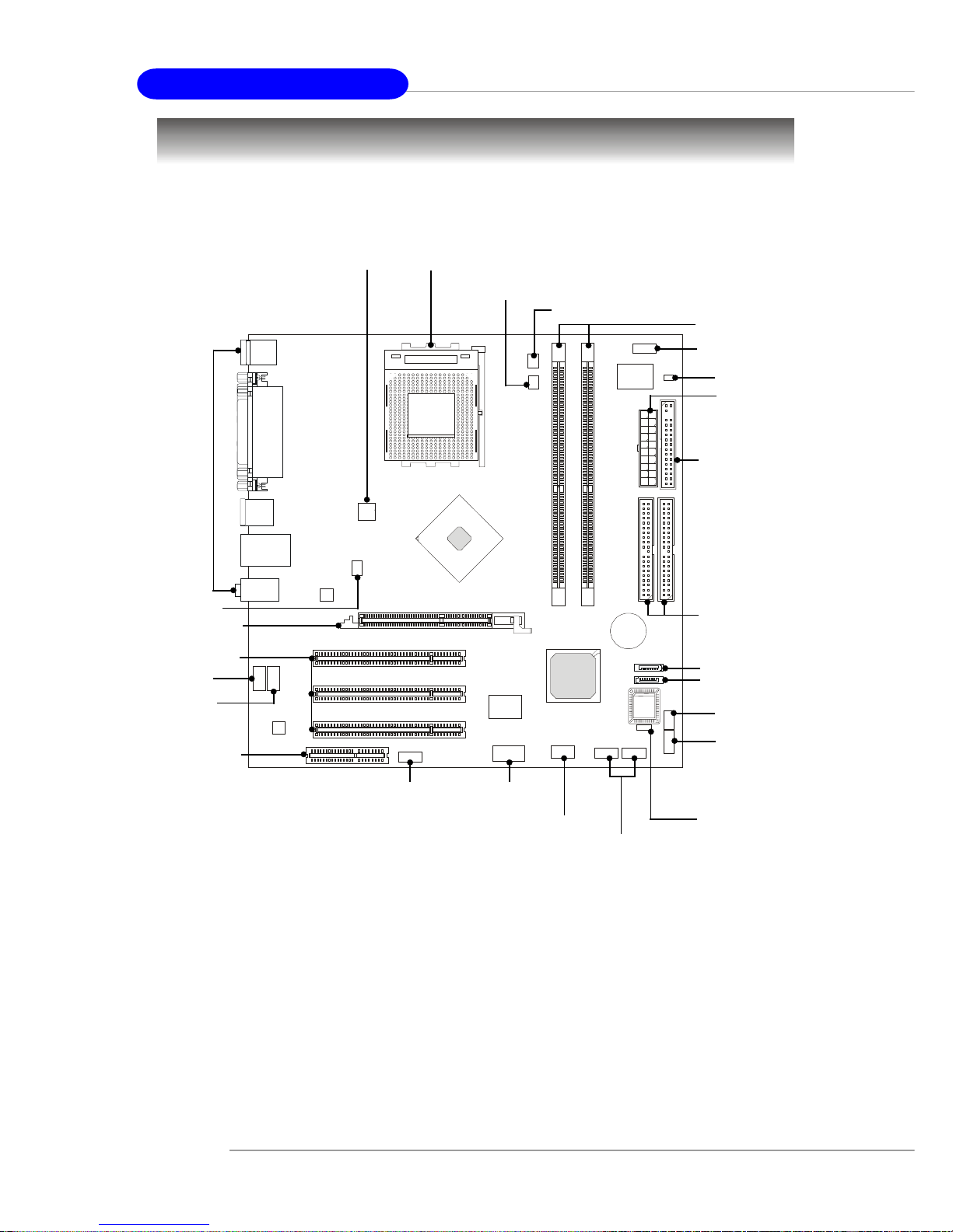
Mainboard Layout
K7N2GM2/K7N2M2 Series (MS-7051G v1.X)
Micro-ATX Mainboard
D
I
M
M
2
D
I
M
M
1
AGP Slot
Top: mouse
Bottom: keyboard
Top:
Line-Out
Bottom:Mic
Line-In
Middle:
JAUD1
AUX_IN1
JCD1
JSP1
Codec
REALTEK
RTL8201CL
B
A
T
T
+
BIOS
Winbond
W83627THF
NVIDIA
nFORCE 2
MCP
RAID
I
D
E
1
I
D
E
2
FDD1
JCOM2
PCI Slot 1
PCI Slot 2
PCI Slot 3
CPU_FAN1
SYS_FAN1
JFP1
JFP2
JPW1
A
T
X
P
o
w
e
r
S
u
p
p
l
y
JBAT1
JCI1
JTV1
JUSB1
SATA2
SATA1
JUSB2
CNR1
J1394_1 (optional)
SOCKET 462
1-6
MS-7051G M-ATX Mainboard
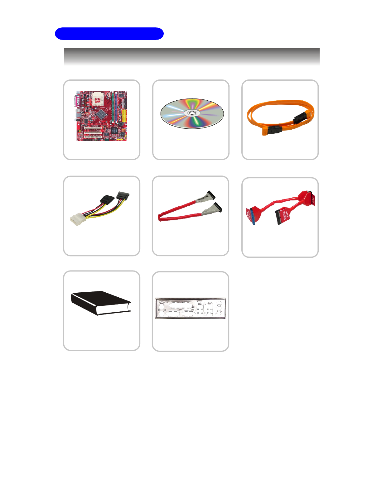
Packing Contents
Power Cable
SATA Cable (Optional)
User’s Guide
MSI motherboard
MSI Driver/Utility CD
Round Cable of
IDE Devices
Round Cable of
Floppy Disk
Back IO Shield

2-1
Hardware Setup
Chapter 2. Hardware Setup
This chapter tells you how to install the CPU, memory modules,
and expansion cards, as well as how to setup the jumpers on the
mainboard. Also, it provides the instructions on connecting the peripheral devices, such as the mouse, keyboard, etc.
While doing the installation, be careful in holding the components and follow the installation procedures.
Hardware Setup
2-2
MS-7051G M-ATX Mainboard
SOCKET 462
Quick Components Guide
JBAT1, p.2-23
DDR DIMMs, p.2-6
CPU, p.2-3
CPU_FAN1, p.2-14
FDD1, p.2-14
IDE1/2, p.2-15
JUSB1/2,
p.2-19
JAUD1,
p.2-18
JPW1, p.2-8
SYS_FAN1, p.2-14
Back Panel
I/O, p.2-9
JTV1, p.2-21
CNR slot, p.2-24
AGP slot, p.2-24
PCI slots, p.2-24
JCD1, p.2-18
AUX_IN1,
p.2-16
J1394_1,
p.2-20
(optional)
JSP1,
p.2-22
JFP1, p.2-17
SATA1, p.2-16
SATA2, p.2-16
JWR1, p.2-8
JCI1, p.2-19
JCOM2, p.2-19
JFP2, p.2-17

2-3
Hardware Setup
Central Processing Unit: CPU
MSI Reminds You...
Overheating
Overheating will seriously damage the CPU and system, always make
sure the cooling fan can work properly to protect the CPU from
overheating.
Replacing the CPU
While replacing the CPU, always turn off the ATX power supply or
unplug the power supply’s power cord from grounded outlet first to
ensure the safety of CPU.
Overclocking
This motherboard is designed to support overclocking. However,
please make sure your components are able to tolerate such abnormal setting, while doing overclocking. Any attempt to operate beyond
product specifications is not recommended. We do not guarantee
the damages or risks caused by inadequate operation or beyond product specifications.
The mainboard supports AMD® Athlon™, Athlon™ XP and Duron™ processors
in the 462 pin package. The mainboard uses a CPU socket called Socket A for easy
CPU installation. When you are installing the CPU, make sure the CPU has a heat
sink and a cooling fan attached on the top to prevent overheating. If you do
not find the heat sink and cooling fan, contact your dealer to purchase and install
them before turning on the computer.
For the latest information about CPU, please visit http://www.msi.com.tw/
program/products/mainboard/mbd/pro_mbd_cpu_support.php.
CPU Core Speed Derivation Procedure
CPU Clock multiplied by Core/Bus ratio equals the CPU core speed.
For example:
If CPU Clock = 100MHz
Core/Bus ratio = 14
then CPU core speed = Host Clock x Core/Bus ratio
= 100MHz x 14
= 1.4 GHz
2-4
MS-7051G M-ATX Mainboard
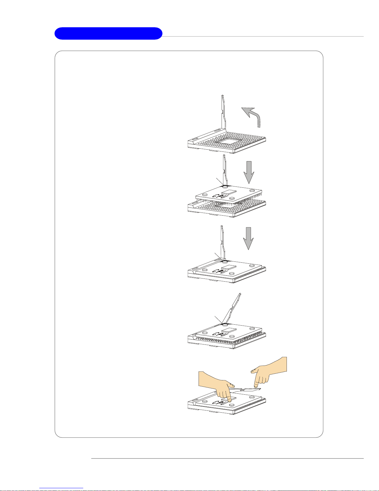
1. Please turn off the power and
unplug the power cord before
installing the CPU.
2. Pull the lever sideways away
from the socket. Make sure to
raise the lever up to a 90-degree
angle.
3. Look for the gold arrow. The gold
arrow should point towards the
lever pivot. The CPU can only fit
in the correct orientation.
4. If the CPU is correctly installed,
the pins should be completely
embedded into the socket and
can not be seen. Please note
that any violation of the correct
installation procedures may
cause permanent damages to
your mainboard.
5. Press the CPU down firmly into
the socket and close the lever.
As the CPU is likely to move while
the lever is being closed,
always close the lever with your
fingers pressing tightly on top of
the CPU to make sure the CPU is
properly and completely
embedded into the socket.
CPU Installation Procedures for Socket 462
Open Lever
Gold arrow
Gold arrow
90 degree
Correct CPU placement
Incorrect CPU placement
Gold arrow
Sliding
Plate
Close
Lever
Press down
the CPU
X
O
2-5
Hardware Setup
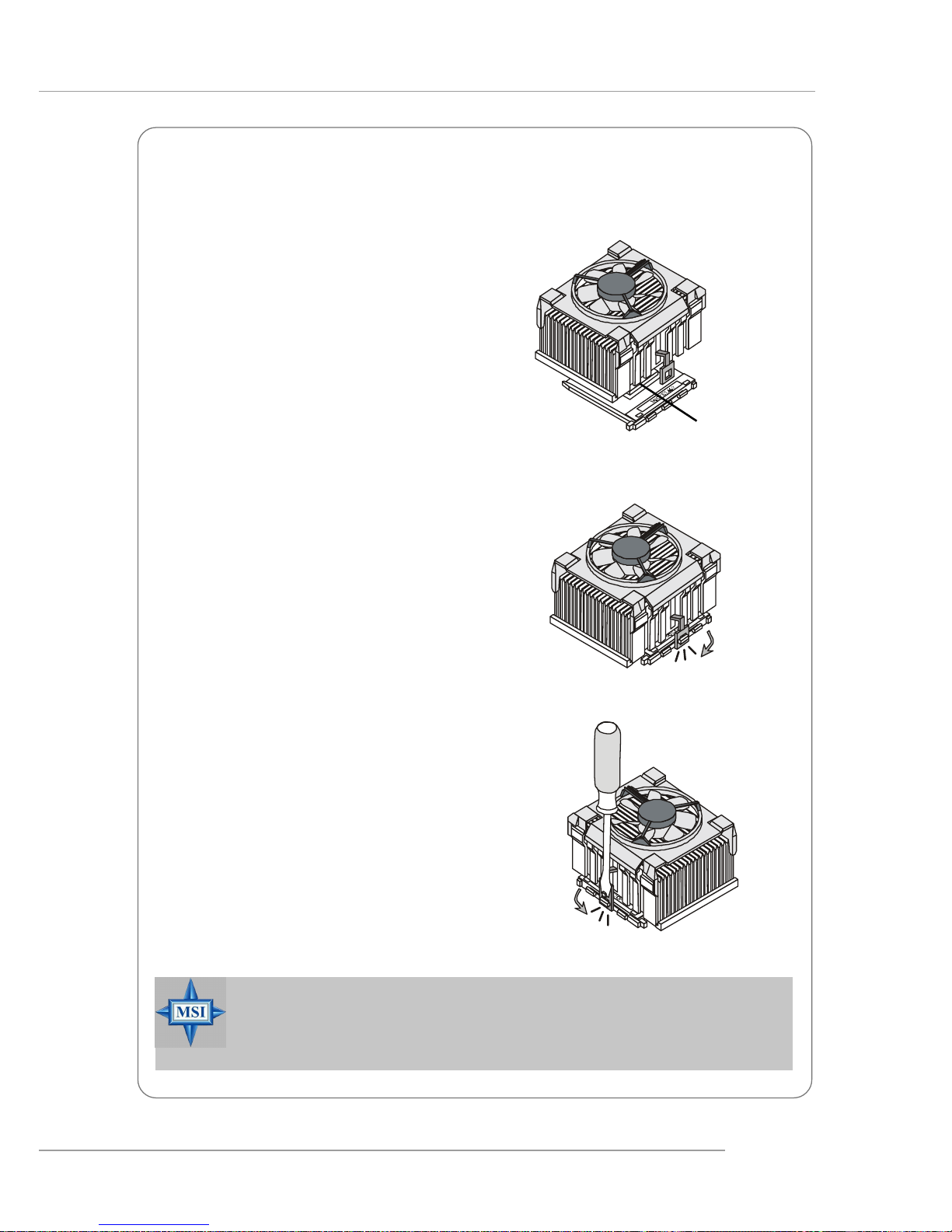
The following instructions will guide you
through the heat sink installation
procedures. Please consult your agent
for the proper CPU cooler set.
1. Position your CPU cooler set onto the
CPU.
2. Use one end of the clip to hook the
latch of the CPU sliding plate.
3. Hook the other latch to fix the cooling
fan set. You may need a screw
drive to press down the other side
of the clip.
4. Connect the fan to the power supply
connector provided on your
mainboard.
Installing AMD Athlon CPU (Socket 462) Cooler Set
Apply some heat
sink paste
MSI Reminds You...
Please apply some heat sink paste on top of CPU to dissipate the heat
more effectively.
2-6
MS-7051G M-ATX Mainboard
Memory
The mainboard provides 2 slots for 184-pin DDR SDRAM DIMM (Double In-Line Memory
Module) modules and supports the memory size up to 2GB. You can install DDR266/
333/400 modules on the DDR DIMM slots (DDR 1~2).
For the updated supporting memory modules, please visit http://www.msi.com.tw/
program/products/mainboard/mbd/pro_mbd_trp_list.php.
DDR DIMM Slots
(DDR 1~2)
Introduction to DDR SDRAM
DDR (Double Data Rate) SDRAM is similar to conventional SDRAM, but doubles the
rate by transferring data twice per cycle. It uses 2.5 volts as opposed to 3.3 volts
used in SDR SDRAM, and requires 184-pin DIMM modules rather than 168-pin DIMM
modules used by SDR SDRAM.
2-7
Hardware Setup
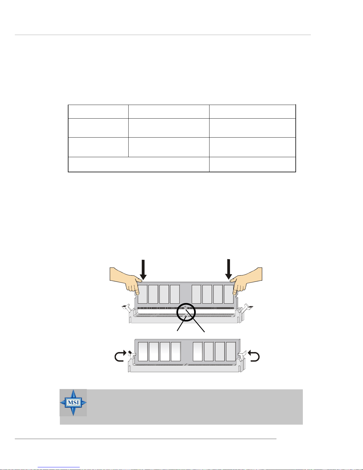
Installing DDR Modules
1. The DDR DIMM has only one notch on the center of module. The module will
only fit in the right orientation.
2. Insert the DIMM memory module vertically into the DIMM slot. Then push it in
until the golden finger on the memory module is deeply inserted in the socket.
3. The plastic clip at each side of the DIMM slot will automatically close.
MSI Reminds You...
You can barely see the golden finger if the module is properly inserted in the socket.
DIMM Module Combination
Install at least one DIMM module on the slots. You can install either single- or doublesided modules in any order to meet your own needs.
Memory modules can be installed in any combination as follows:
S: Single Side D: Double Side
Slot Memory Module T otal Memory
DDR 2
(Bank 2 & 3) S/D 64MB~1GB
Maximum System Memory Supported 64MB~2GB
DDR 1
(Bank 0 & 1) S/D 64MB~1GB
Volt
Notch

2-8
MS-7051G M-ATX Mainboard
Power Supply
The mainboard supports ATX power supply for the power system. Before inserting
the power supply connector, always make sure that all components are installed
properly to ensure that no damage will be caused.
ATX 20-Pin Power Connector: JWR1
This connector allows you to connect to an ATX power supply. To connect to the ATX
power supply, make sure the plug of the power supply is inserted in the proper
orientation and the pins are aligned. Then push down the power supply firmly into the
connector.
MSI Reminds You...
1. These two connectors connect to the ATX power supply and have to
work together to ensure stable operation of the mainboard.
2. Power supply of 300 (and up) watt is highly recommended for system
stability.
PIN SIGNAL
11 3.3V
12 -12V
13 GND
14 PS_ON
15 GND
16 GND
17 GND
1 8 -5V
19 5V
20 5V
PIN SIGNAL
1 3.3V
2 3.3V
3 GND
45V
5 GND
65V
7 GND
8 PW_OK
9 5V_SB
10 12V
JWR1 Pin Definition
JWR1
10
1
20
11
PIN SIGNAL
1 GND
2 GND
312V
412V
JPW1 Pin Definition
JPW1
1
3
2
4
ATX 12V Power Connector: JPW1
This 12V power connector is used to provide power to the CPU.
2-9
Hardware Setup
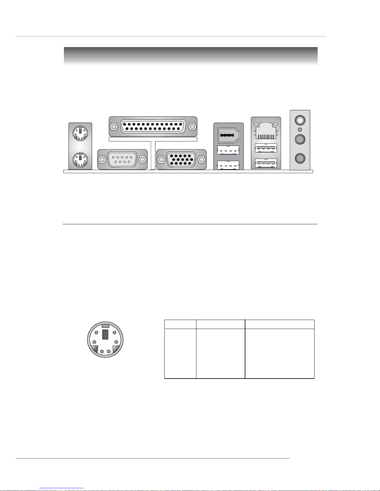
The back panel provides the following connectors:
Back Panel
Mouse
Printer Port
USB Ports
Keyboard
MIC
LAN
VGA Port
USB Ports
1394
(optional)
COM Port
L-in
L-out
Mouse Connector
The mainboard provides a standard PS/2® mouse mini DIN connector for attaching a
PS/2® mouse. You can plug a PS/2® mouse directly into this connector. The connector location and pin assignments are as follows:
PIN SIGNAL DESCRIPTION
1 Mouse DA T A Mouse DAT A
2 NC No connection
3 GND Ground
4 VCC +5V
5 Mouse Clock Mouse clock
6 NC No connection
Pin Definition
PS/2 Mouse (6-pin Female)
2
1
3
4
5
6
2-10
MS-7051G M-ATX Mainboard
PS/2 Keyboard
(6-pin Female)
2
1
3
4
5
6
PIN SIGNAL DESCRIPTION
1 Mouse/Keyboard Data Mouse/Keyboard data
2 NC No connection
3 GND Ground
4 VCC +5V
5 Mouse/Keyboard Clock Mouse/Keyboard clock
6 NC No connection
Pin Definition
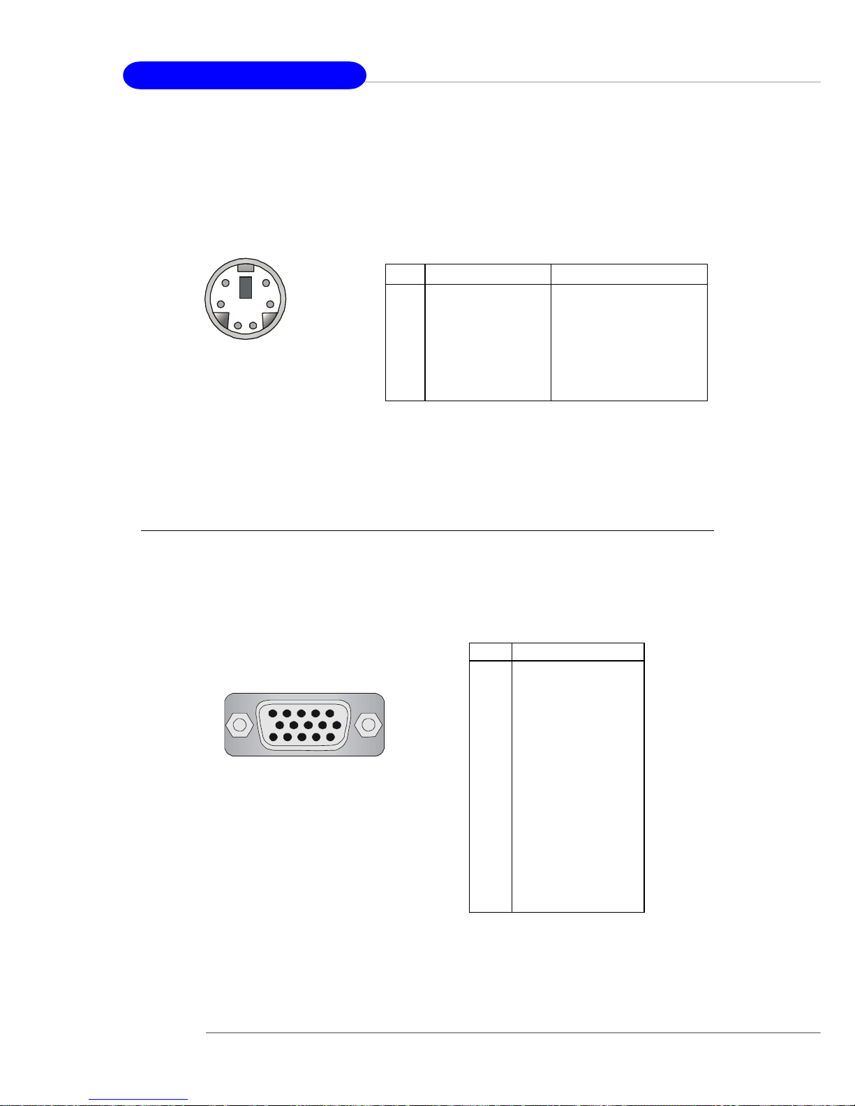
VGA Connector:
The mainboard provides a DB 15-pin female connector to connect a VGA monitor.
Keyboard Connector
The mainboard provides a standard PS/2® keyboard mini DIN connector for attaching
a PS/2® keyboard. You can plug a PS/2® keyboard directly into this connector.
VGA Connector, DB 15-pin
1
5
11
15
Pin Signal Description
1 RED
2 GREEN
3 BLUE
4 N/C
5 GND
6 GND
7 GND
8 GND
9 +5V
10 GND
1 1 N/C
12 SDA
13 Horizontal Sync
14 Vertical Sync
15 SCL
2-11
Hardware Setup
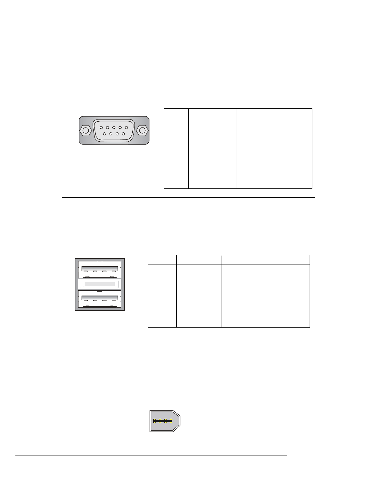
Serial Port Connector:
The mainboard offers one 9-pin male DIN connector as the serial port. The port is a
16550A high speed communication port that sends/receives 16 bytes FIFOs. Yo u
can attach a serial mouse or other serial devices directly to the connector.
USB Connectors
The mainboard provides an OHCI (Open Host Controller Interface) Universal Serial
Bus root for attaching USB devices such as keyboard, mouse or other USB-compatible devices. You can plug the USB device directly into the connector.
USB Ports
1 2 3 4
5 6 7 8
PIN SIGNAL DESCRIPTION
1 VCC +5V
2 -Data 0 Negative Data Channel 0
3 +Data0 Positive Data Channel 0
4 GND Ground
5 VCC +5V
6 -Data 1 Negative Data Channel 1
7 +Data 1 Positive Data Channel 1
8 GND Ground
USB Port Description
PIN SIGNAL DESCRIPTION
1 DCD Data Carry Detect
2 SIN Serial In or Receive Data
3 SOUT Serial Out or Transmit Data
4 DTR Data T erminal Ready)
5 GND Ground
6 DSR Data Set Ready
7 RTS Request To Send
8 CTS Clear To Send
9 RI Ring Indicate
Pin Definition
(9-Pin Male DIN Connector)
1 2 3 4 5
6 7 8 9
COM port
IEEE 1394 Port (optional)
The back panel provides one standard IEEE 1394 port. The standard IEEE 1394 port
connects to IEEE 1394 devices without external power. The IEEE 1394 high-speed
serial bus complements USB by providing enhanced PC connectivity for a wide range
of devices, including consumer electronics audio/video (A/V) appliances, storage
peripherals, other PCs, and portable devices.
1394 Port

2-12
MS-7051G M-ATX Mainboard
LAN (RJ-45) Jack
The mainboard provides one standard RJ-45 jack for connection to Local Area Network (LAN). You can connect a network cable to the LAN jack.
Giga-bit LAN Pin Definition
PIN SIGNAL DESCRIPTION
1 D0 P Differential Pair 0+
2 D0N Differential Pair 03 D1 P Differential Pair 1+
4 D2 P Differential Pair 2+
5 D2N Differential Pair 26 D1N Differential Pair 17 D3 P Differential Pair 3+
8 D3N Differential Pair 3-
RJ-45 LAN Jack
MSI Reminds You...
For advanced audio application, Realtek ALC 655 is provided to
offer support for 6-channel audio operation and can turn rear
audio connectors from 2-channel to 4-/6-channel audio. For more
information on 6-channel audio operation , please refer to
Appendix. Using 4- or 6-Channel Audio Function.
Audio Port Connectors
Line Out is a connector for Speakers or Headphones. Line In is used for external
CD player, Tape player, or other audio devices. Mic is a connector for microphones.
1/8” Stereo Audio Connectors
Line Out
Line In
MIC
2-13
Hardware Setup
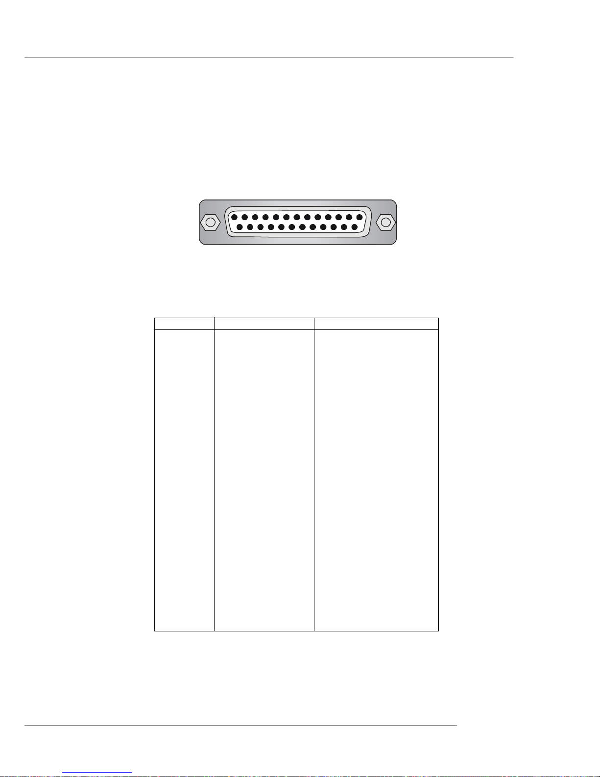
Parallel Port Connector: LPT1
The mainboard provides a 25-pin female centronic connector as LPT. A parallel port
is a standard printer port that supports Enhanced Parallel Port (EPP) and Extended
Capabilities Parallel Port (ECP) mode.
13 1
14
25
PIN SIGNAL DESCRIPTION
1 STROBE Strobe
2 DA T A0 Data0
3 DA T A1 Data1
4 DA T A2 Data2
5 DA T A3 Data3
6 DA T A4 Data4
7 DA T A5 Data5
8 DA T A6 Data6
9 DA T A7 Data7
10 ACK# Acknowledge
11 BUSY Busy
12 PE Paper End
1 3 SELECT Select
1 4 AUTO FEED# Automatic Feed
15 ERR# Error
1 6 INIT# Initialize Printer
17 SLIN# Select In
18 GND Ground
19 GND Ground
20 GND Ground
21 GND Ground
22 GND Ground
23 GND Ground
24 GND Ground
25 GND Ground
Pin Definition
2-14
MS-7051G M-ATX Mainboard
The mainboard provides connectors to connect to FDD, IDE HDD, case, LAN, USB
Ports and CPU/System FAN.
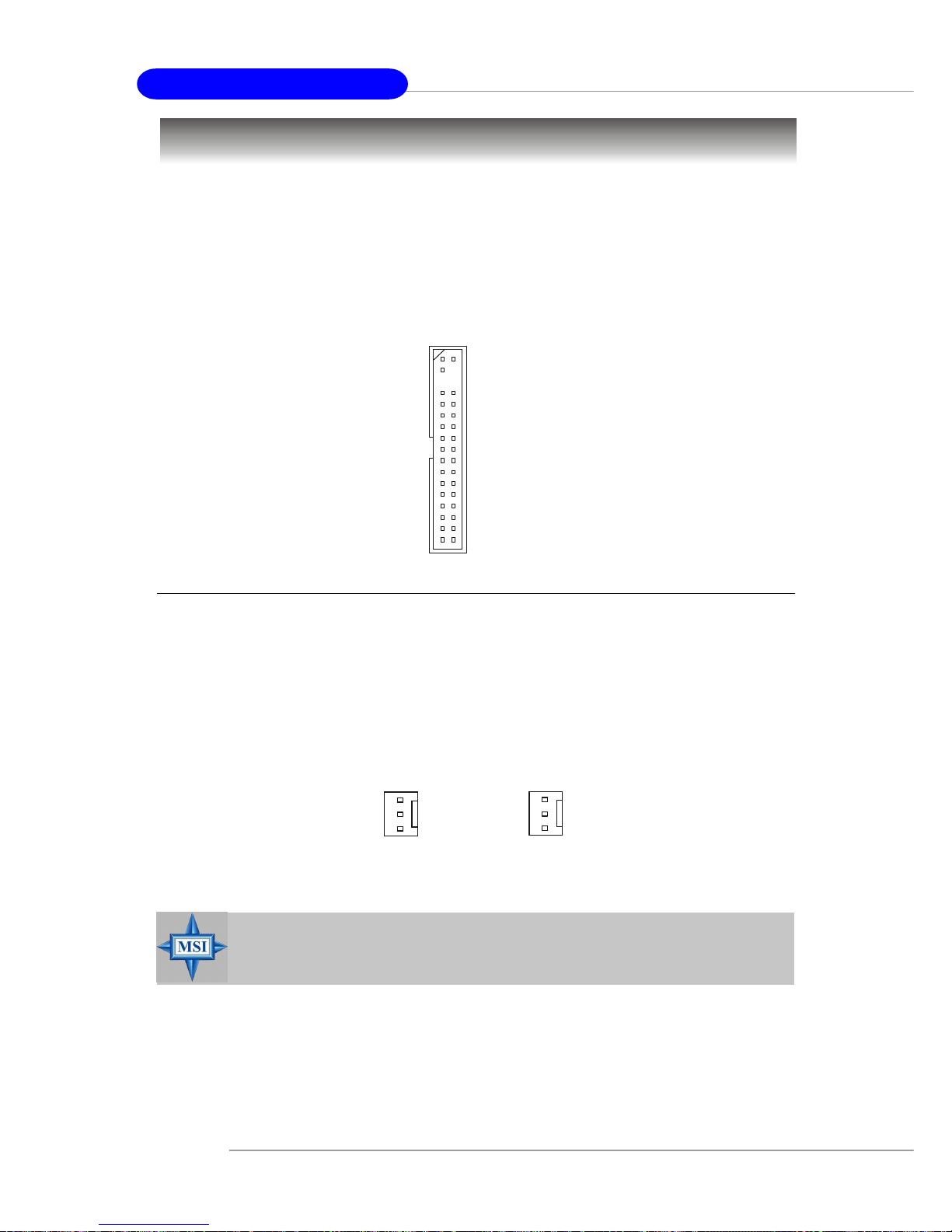
Floppy Disk Drive Connector: FDD1
The mainboard provides a standard floppy disk drive connector that supports 360K,
720K, 1.2M, 1.44M and 2.88M floppy disk types.
Connectors
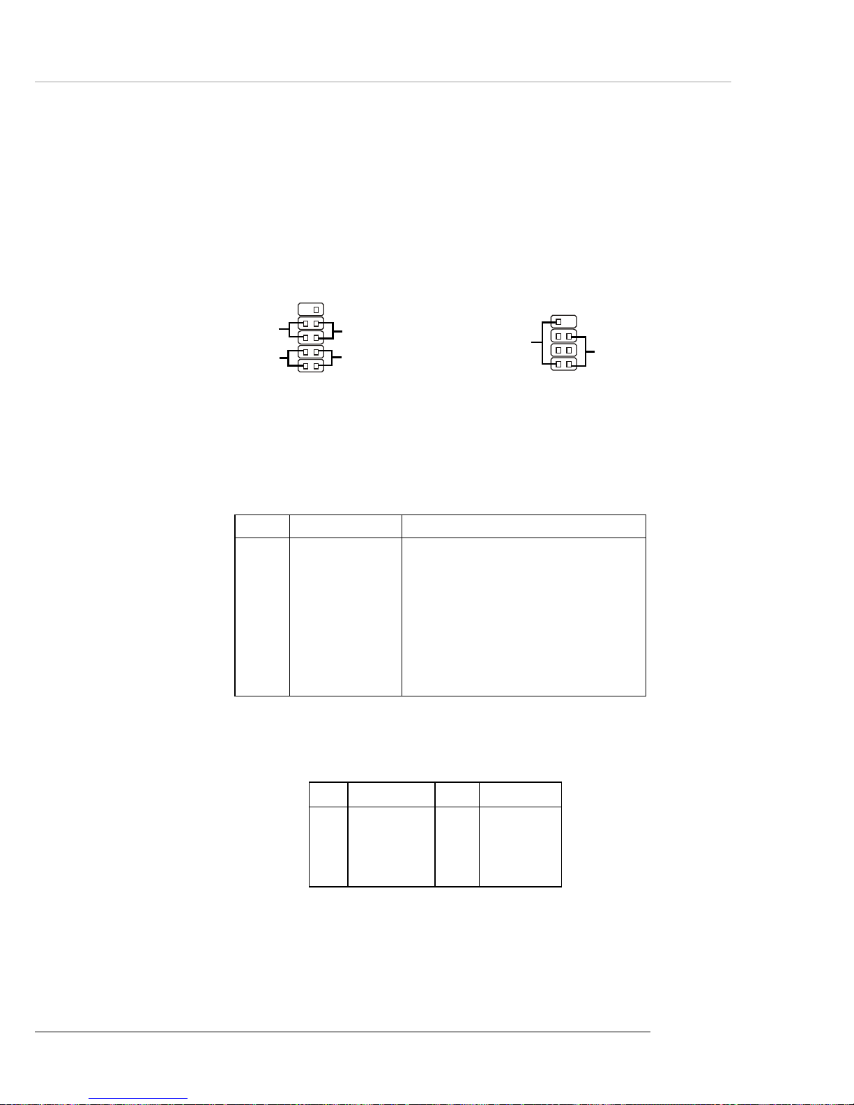
Fan Power Connectors: CPU_F AN1 & SYS_F AN1
The CPU_FAN1 (processor fan) and SYS_FAN1 (system fan 1) support system
cooling fan with +12V. It supports three-pin head connector. When connecting the
wire to the connectors, always take note that the red wire is the positive and should
be connected to the +12V, the black wire is Ground and should be connected to GND.
If the mainboard has a System Hardware Monitor chipset on-board, you must use a
specially designed fan with speed sensor to take advantage of the CPU fan control.
MSI Reminds You...
1. Always consult the vendors for proper CPU cooling fan.
2. Please refer to the recommend CPU fans at AMD® official website.
CPU_F AN1
Sensor
+12V
GND
SYS_FAN1
Sensor
+12V
GND
FDD1
2-15
Hardware Setup
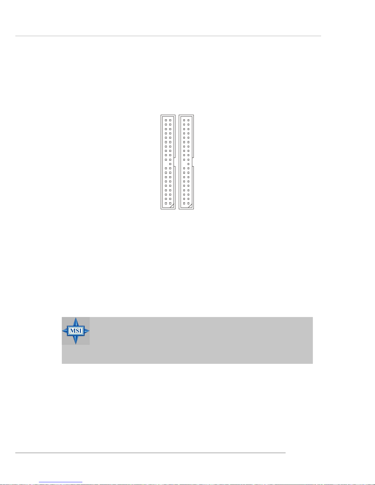
Hard Disk Connectors: IDE1 & IDE2
The mainboard has a 32-bit Enhanced PCI IDE and Ultra DMA 33/66/100/133 controller
that provides PIO mode 0~4, Bus Master, and Ultra DMA 33/66/100/133 function. You
can connect up to four hard disk drives, CD-ROM, 120MB Floppy (reserved for future
BIOS) and other devices.
IDE1 (Primary IDE Connector)
The first hard drive should always be connected to IDE1. IDE1 can connect a Master
and a Slave drive. You must configure second hard drive to Slave mode by setting the
jumper accordingly.
IDE2 (Secondary IDE Connector)
IDE2 can also connect a Master and a Slave drive.
IDE1IDE2
MSI Reminds You...
If you install two hard disks on cable, you must configure the second
drive to Slave mode by setting its jumper. Refer to the hard disk
documentation supplied by hard disk vendors for jumper setting
instructions.
2-16
MS-7051G M-ATX Mainboard
Aux Line-In Connector: AUX_IN1
The connector is for DVD add-on card with Line-in connector.
GND
R
L
AUX_IN1
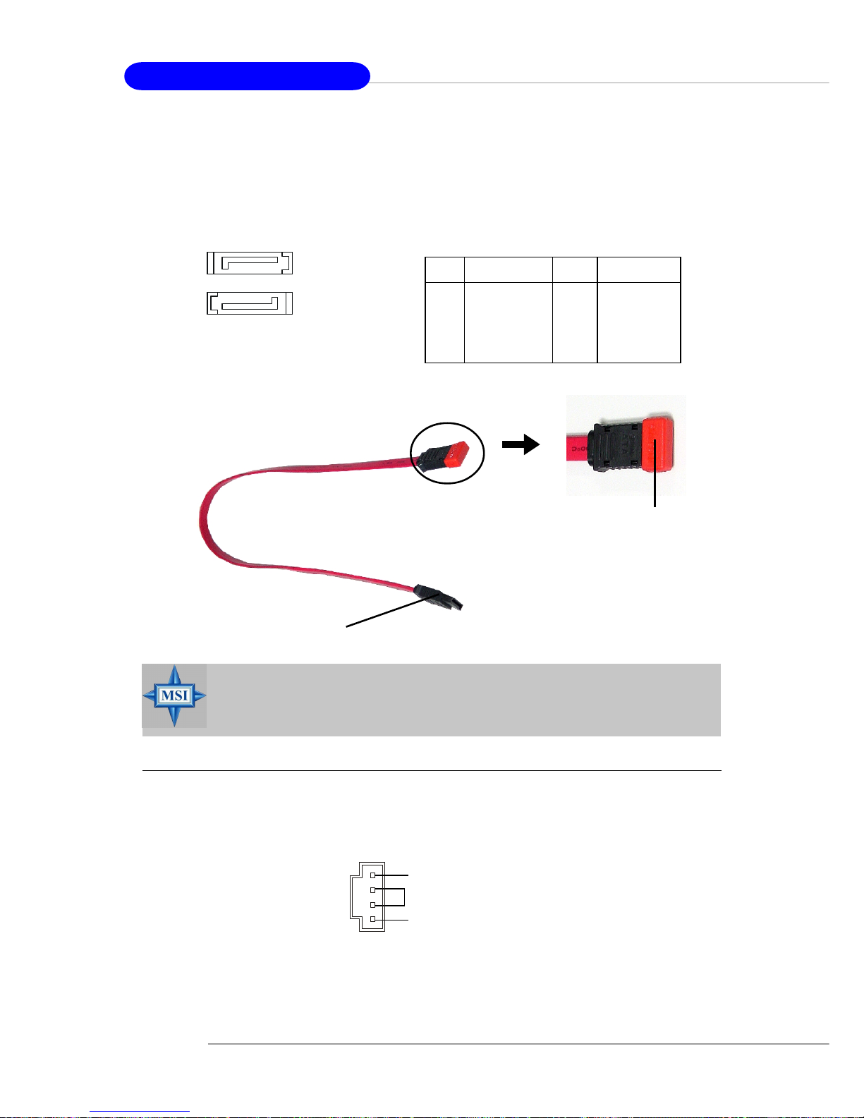
MSI Reminds You...
Please do not fold the serial ATA cable in a 90-degree angle, which will
cause the loss of data during the transmission.
Connect to serial ATA ports
Take out the dust cover and
connect to the hard disk
devices
Serial A TA cable
PIN SIGNAL PIN SIGNAL
1 GND 2 TXP
3 TXN 4 GND
5 RXN 6 RXP
7 GND
SA TA1/SA T A2 Pin Definition
7
1
SATA2
SATA1
1
7
Serial A TA HDD Connectors: SA TA1 & SA TA2
The mainboard provides dual high-speed Serial ATA interface ports. The ports support 1st generation Serial ATA data rates of 150MB/s and are fully compliant with
Serial ATA 1.0 specifications. Each Serial ATA connector can connect to 1 hard disk
drive.
2-17
Hardware Setup
Front Panel Connectors: JFP1 & JFP2
The mainboard provides two front panel connectors for electrical connection to the
front panel switches and LEDs. JFP1 is compliant with Intel® Front Panel I/O Connectivity Design Guide.
PIN SIGNAL DESCRIPTION
1 HD_LED_P Hard disk LED pull-up
2 FP PWR/SLP MSG LED pull-up
3 HD_LED_N Hard disk active LED
4 FP PWR/SLP MSG LED pull-up
5 RST_SW_N Reset Switch low reference pull-down to GND
6 PWR_SW_P Power Switch high reference pull-up
7 RST_SW_P Reset Switch high reference pull-up
8 PWR_SW_N Power Switch low reference pull-down to GND
9 RSVD_DNU Reserved. Do not use.
JFP1 Pin Definition
PIN SIGNAL PIN SIGNAL
1 GND 2 SPK3 SLED 4 BUZ+
5 PLED 6 BUZ7 NC 8 SPK+
JFP2 Pin Definition
JFP2
7
8
Power
LED
Speaker
12
JFP1
1
2
910
HDD
LED
Reset
Switch
Power
LED
Power
Switch
 Loading...