

MSI K8M Neo-V, MS-7032, K8T Neo-V Instruction Manual
i
FCC-B Radio Frequency Interference Statement
This equipment has been tested and found to comply with the limits for a class B digital device, pursuant to part 15 of
the FCC rules. These limits are designed to provide reasonable protection against harmful interference when the
equipment is operated in a commercial environment. This equipment generates, uses and can radiate radio frequency
energy and, if not installed and used in accordance with the instruction manual, may cause harmful interference to
radio communications. Operation of this equipment in a residential area is likely to cause harmful interference, in
which case the user will be required to correct the interference at his own expense.
Notice 1
The changes or modifications not expressly approved by the party responsible for compliance could void the user’s
authority to operate the equipment.
Notice 2
Shielded interface cables and A.C. power cord, if any, must be used in order to comply with the emission limits.
VOIR LA NOTICE D’NSTALLATION AVANT DE RACCORDER AU RESEAU.
Micro-Star International
MS-7032
This device complies with Part 15 of the FCC Rules. Operation is subject to the following two conditions:
(1) this device may not cause harmful interference, and
(2) this device must accept any interference received, including interference that may cause undesired operation
G52-M7032X2

ii
Copyright Notice
The material in this document is the intellectual property of MICRO-STAR INTERNATIONAL. We take every care in
the preparation of this document, but no guarantee is given as to the correctness of its contents. Our products are
under continual improvement and we reserve the right to make changes without notice.
Trademarks
All trademarks are the properties of their respective owners.
AMD, Athlon™ Athlon™XP, Thoroughbred™ and Duron™ are registered trademarks of AMD Corporation.
Intel® and Pentium® are registered trademarks of Intel Corporation.
PS/2 and OS® 2 are registered trademarks of International Business Machines Corporation.
Microsoft® is a registered trademark of Microsoft Corporation. Windows® 98/2000/NT/XP are registered trademarks
of Microsoft Corporation.
NVIDIA, the NVIDIA logo, DualNet, and nForce are registered trademarks or trademarks of NVIDIA Corporation in the
United States and/or other countries.
Netware® is a registered trademark of Novell, Inc.
Award® is a registered trademark of Phoenix Technologies Ltd.
AMI® is a registered trademark of American Megatrends Inc.
Kensington and MicroSaver are registered trademarks of the Kensington Technology Group.
PCMCIA and CardBus are registered trademarks of the Personal Computer Memory Card International Association.
Revision History
Revision Revision History Date
V1.0 Multi-lingual version for PCB 1.x August 2004
V1.1 Update North Bridge to T800/K8M800 and South Bridge to VT8237/8237R December 2004

iii
Safety Instructions
1. Always read the safety instructions carefully.
2. Keep this User Manual for future reference.
3. Keep this equipment away from humidity.
4. Lay this equipment on a reliable flat surface before setting it up.
5. The openings on the enclosure are for air convection hence protects the equipment from overheating. Do not
cover the openings.
6. Make sure the voltage of the power source and adjust properly 110/220V before connecting the equipment to the
power inlet.
7. Place the power cord such a way that people can not step on it. Do not place anything over the power cord.
8. Always Unplug the Power Cord before inserting any add-on card or module.
9. All cautions and warnings on the equipment should be noted.
10. Never pour any liquid into the opening that could damage or cause electrical shock.
11. If any of the following situations arises, get the equipment checked by a service personnel:
- The power cord or plug is damaged.
- Liquid has penetrated into the equipment.
- The equipment has been exposed to moisture.
- The equipment does not work well or you can not get it work according to User Manual.
- The equipment has dropped and damaged.
- The equipment has obvious sign of breakage.
12. Do not leave this equipment in an environment unconditioned, storage temperature above 600 C (1400F), it may
damage the equipment.
CAUTION: Danger of explosion if battery is incorrectly replaced. Replace only with
the same or equivalent type recommended by the manufacturer.

iv
Table of Content
English....................................................................1
Deutsch...................................................................15
Français..................................................................31
日 本 語...................................................................45
简体中文...................................................................61
繁體中文...................................................................75
1
Introduction
Thank you for choosing the MS-7032 (K8T Neo-V/K8M Neo-V) v1.X ATX mainboards. This K8T
Neo-V/K8M Neo-V is based on VIA® K8T800/K8M800 North Bridge & VT8237/8237R South Bridge
chipsets and provides eight USB 2.0 ports for high-speed data transmission, and RealTek ALC655 chip
for 6-channel audio output. Designed to fit the advanced AMD® K8 Athlon64 processors, the K8T
Neo-V/K8M Neo-V mainboard delivers a high performance and professional desktop platform solution.
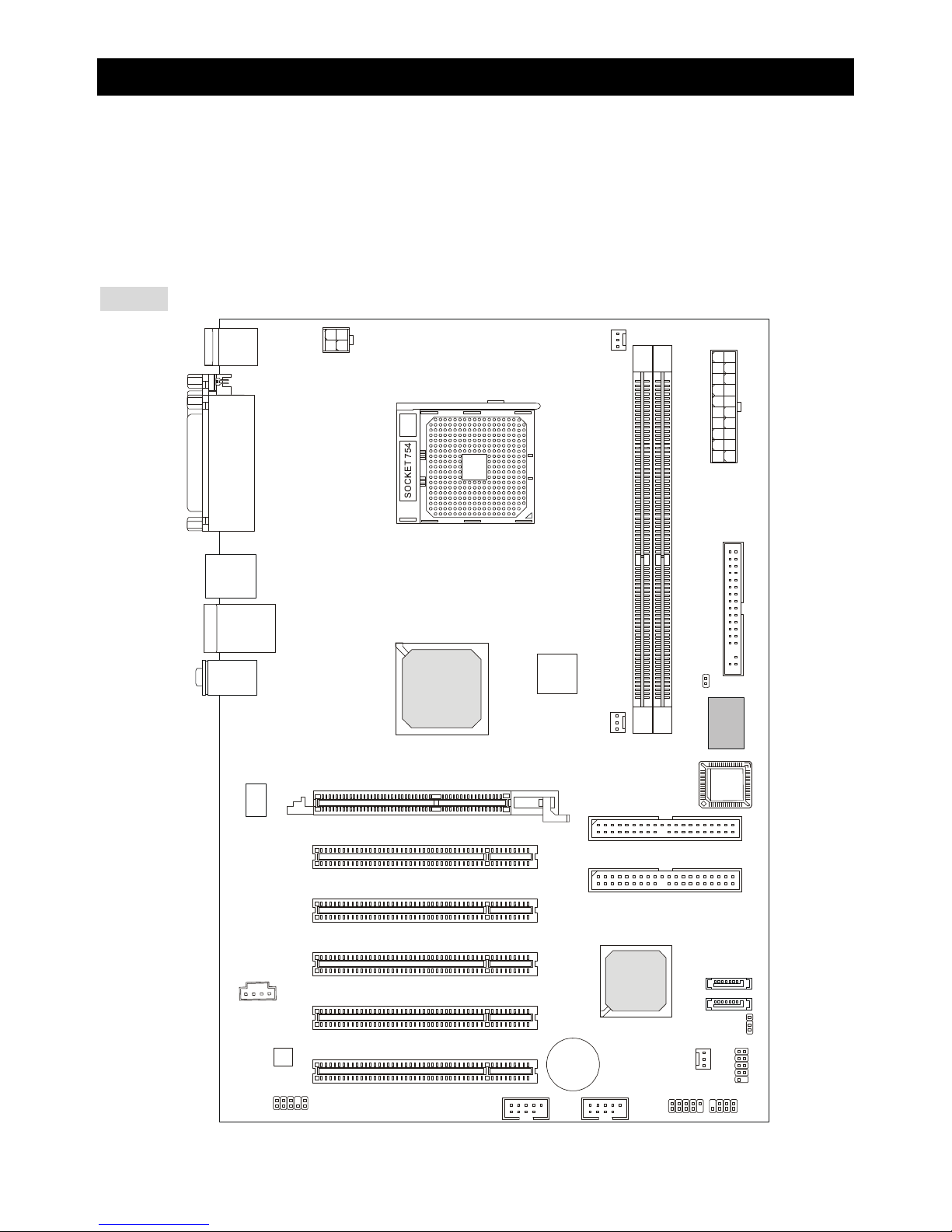
Layout
SFAN1CFAN1JPW
1
PWFAN1
FD D1
SATA2
SATA1
J
4
T:
M:
B:
Line-In
Line-Out
Mic
T: LAN jack
B: USB ports
WinbondW83627TH
F
VIA
K8T800
or
K8M800
AGP Slot
BATT
+
VT8237
DDR 1DDR
2
ATXPower Supply
PCI Slot 5
PCI Slot 4
PCI Slot 3
PCI Slot 2
PCI Slot 1
IDE 2
IDE 1
JFP1
JBAT1
JCASE1
JFP2
JLED
JAUD1
JUSB2JUSB1
Top : Parallel Port
Bottom:
COM A
VGA Port (For K8M Neo-V only)
Top : mouse
Bottom: keyboard
USB port
Cor e C
ell
BIO
S
Codec
RTL8201CL

2
Specifications
CPU
l Supports 64-bit AMD® K8 Athlon64 processor (Socket 754)
l Supports up to 2800+, 3000+, 3100+, 3200+, 3400+, 3700+, or higher CPU
(Please refer to the latest online news at http://www.msi.com.tw/program/products/mainboard/
mbd/pro_mbd_cpu_support.php)
Chipset
l VIA® K8T800 / K8M800 chipset
- HyperTransportTM connection to AMD Athlon64 processor
- 8 or 16 bit control/address/data transfer both directions
- 800/600/400/200 MHz “Double Data Rate” operation both direction
- AGP v3.0 compliant with 8x transfer mode
l VIA® VT8237/8237R chipset (487 BGA)
- Integrated Faster Ethernet LPC
- Integrated Hardware Sound Blaster/Direct Sound AC97 audio
- Ultra DMA 33/66/100/133 master mode PCI EIDE controller
- Supports 2 Serial ATA RAID0/1
- Supports 8 USB2.0 ports
Main Memory
l Supports DDR266/333/400 DDR SDRAM for two 184-pin DDR DIMMs
l Supports a maximum memory size of 2GB
(For the updated supporting memory modules, please visit http://www.msi.com.tw/program/products/
mainboard/mbd/pro_mbd_trp_list.php to refer the memory module part in the test report.)
Slots
l One (Accelerated Graphics Port) AGP slot (AGP 3.0 specification compliant)
l Five 32-bit Master 3.3v / 5v PCI Bus slots
On-Board IDE
l An IDE controller on the VIA® VT8237/8237R chipset provides IDE HDD/CD-ROM with PIO, Bus
Master and Ultra DMA 33/66/100/133 operation modes
l Can connect up to 4 IDE devices
l Serial ATA/150 controller integrated by VT8237/8237R
- Up to 150MB/s transfer rate
- Can connect up to two Serial ATA drives with RAID0 & RAID1.

3
On-Board Peripherals
l On-Board Peripherals include:
- 1 floppy port supports 1 FDD with 360K, 720K, 1.2M, 1.44M and 2.88Mbytes
- 1 serial port (COMA)
- 1 parallel port supports SPP/EPP/ECP mode
- 1 Audio port
- 1 D-Bracket2 pinheader
- 1 RJ-45 LAN Jack
- 8 USB Ports (Front x 4 / Rear x 4)
- 1 VGA Port (For K8M Neo-V only)
Audio
l 6 channels software audio codec RealTek ALC655.
- Compliance with AC97 v2.3 Spec.
- Meet PC2001 audio performance requirement.
LAN
l 10/100Mbps Realtek® 8201CL
l Gigabit Ethernet LAN Realtek® 8110SB (optional)
- Both integrated Fast Ethernet MAC and PHY in one chip.
- Both compliant with PCI V2.2.
- Both Support ACPI Power Management.
BIOS
l The mainboard BIOS provides “Plug & Play” BIOS which detects the peripheral devices and
expansion cards of the board automatically.
l The mainboard provides a Desktop Management Interface (DMI) function which records your
mainboard specifications.
Dimension
l ATX Form Factor: 305 mm (L) x 210 mm (W).
Mounting
l 6 mounting holes.
4
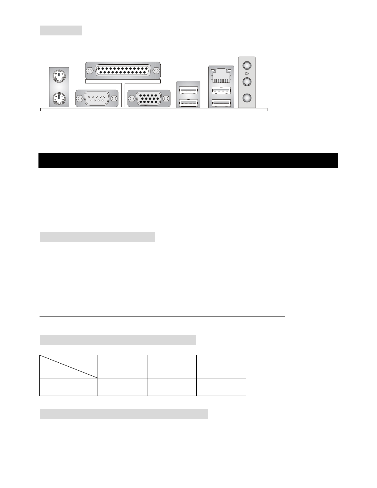
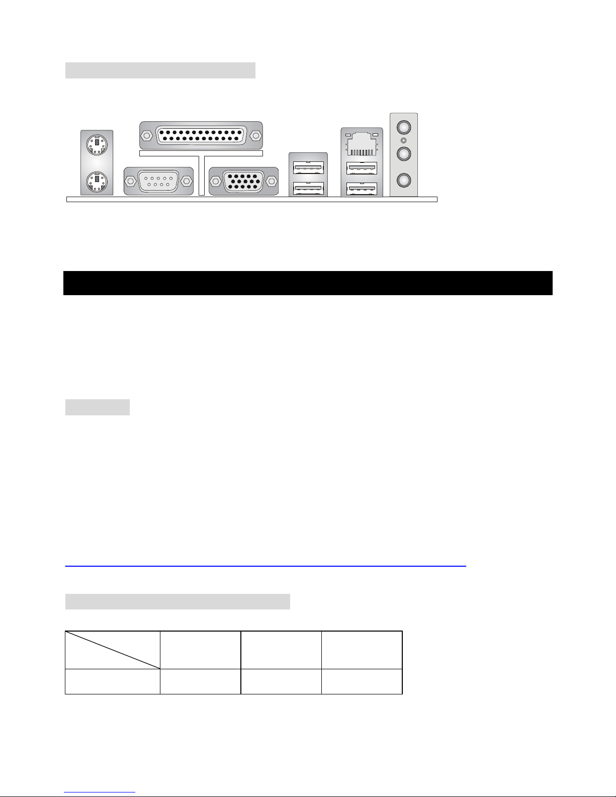
Rear Panel
The back panel provides the following connectors:
Mouse
Keyboard
Parallel
COM A VGA Port
(For K8M Neo-V only)
USB Ports
LAN
L-in
L-out
MIC
Hardware Setup
This chapter tells you how to install the CPU, memory modules, and expansion cards, as well as how to
setup the jumpers on the mainboard. It also provides the instructions on connecting the peripheral
devices, such as the mouse, keyboard, etc. While doing the installation, be careful in holding the
components and follow the installation procedures.
Central Processing Unit: CPU
The mainboard supports AMD® Athlon64 processor. The mainboard uses a CPU socket called
Socket-754 for easy CPU installation. When you are installing the CPU, make sure the CPU has a heat
sink and a cooling fan attached on the top to prevent overheating. If you do not have the heat sink and
cooling fan, contact your dealer to purchase and install them before turning on the computer.
For the latest information about CPU, please visit
http://www.msi.com.tw/program/products/mainboard/mbd/pro_mbd_cpu_support.php
Memory Speed/CPU FSB Support Matrix
Memory
DDR 266 DDR333 DDR400
FSB200 OK OK OK
CPU Installation Procedures for Socket 754
1. Please turn off the power and unplug the power cord before installing the CPU.
2. Pull the lever sideways away from the socket. Make sure to raise the lever up to a 90-degree angle.
FSB

5
3. Look for the gold arrow. The gold arrow should point towards the lever pivot. The CPU can only fit in
the correct orientation.
4. If the CPU is correctly installed, the pins should be completely embedded into the socket and can
not be seen. Please note that any violation of the correct installation procedures may cause
permanent damages to your mainboard.
5. Press the CPU down firmly into the socket and close the lever. As the CPU is likely to move while
the lever is being closed, always close the lever with your fingers pressing tightly on top of the CPU
to make sure the CPU is properly and completely embedded into the socket.
Installing AMD Athlon64 CPU Cooler Set
As processor technology pushes to faster speeds and higher performance, thermal management
becomes increasingly important. To dissipate heat, you need to attach the CPU cooling fan and heat
sink on top of the CPU. Follow the instructions below to install the Heat sink and Fan:
1. Detach the shield of the back plate’s paster.
2. Turn over the mainboard, and install the back plate to the proper position.
3. Turn over the mainboard again, and place the mainboard on the flat surface. Locate the two
screw holes of the mainboard.
4. Align the retention mechanism and the back plate. Fix the retention mechanism and the back
plate with two screws.
5. Position the cooling set onto the retention mechanism. Hook one end of the clip to hook first, and
then press down the other end of the clip to fasten the cooling set on the top of the retention
mechanism.
6. Locate the Fix Lever, Safety Hook and the Fixed Bolt. Lift up the intensive fixed lever.
7. Fasten down the lever and then make sure the safety hook completely clasps the fixed bolt of the
retention mechanism.
8. Attach the CPU Fan cable to the CPU fan connector on the mainboard.
MSI Reminds You...
Overheating
Overheating will seriously damage the CPU and system, always make sure the cooling fan can work
properly to protect the CPU from overheating.
6
Replacing the CPU
While replacing the CPU, always turn off the ATX power supply or unplug the power supply’s power
cord from grounded outlet first to ensure the safety of CPU.
Memory
The mainboard provides 2 slots for 184-pin DDR SDRAM DIMM (Double In-Line Memory Module)
modules and supports the memory size up to 2GB. You can install PC3200/DDR400, PC2700/DDR333,
or PC2100/DDR266 unbuffered DIMM modules on the DDR DIMM slots (DDR 1~2). Plugging
memories in DIMM1 and DIMM2 makes the system reach the optimum system performance.
For the updated supporting memory modules, please visit
http://www.msi.com.tw/program/products/mainboard/mbd/pro_mbd_trp_list.php.
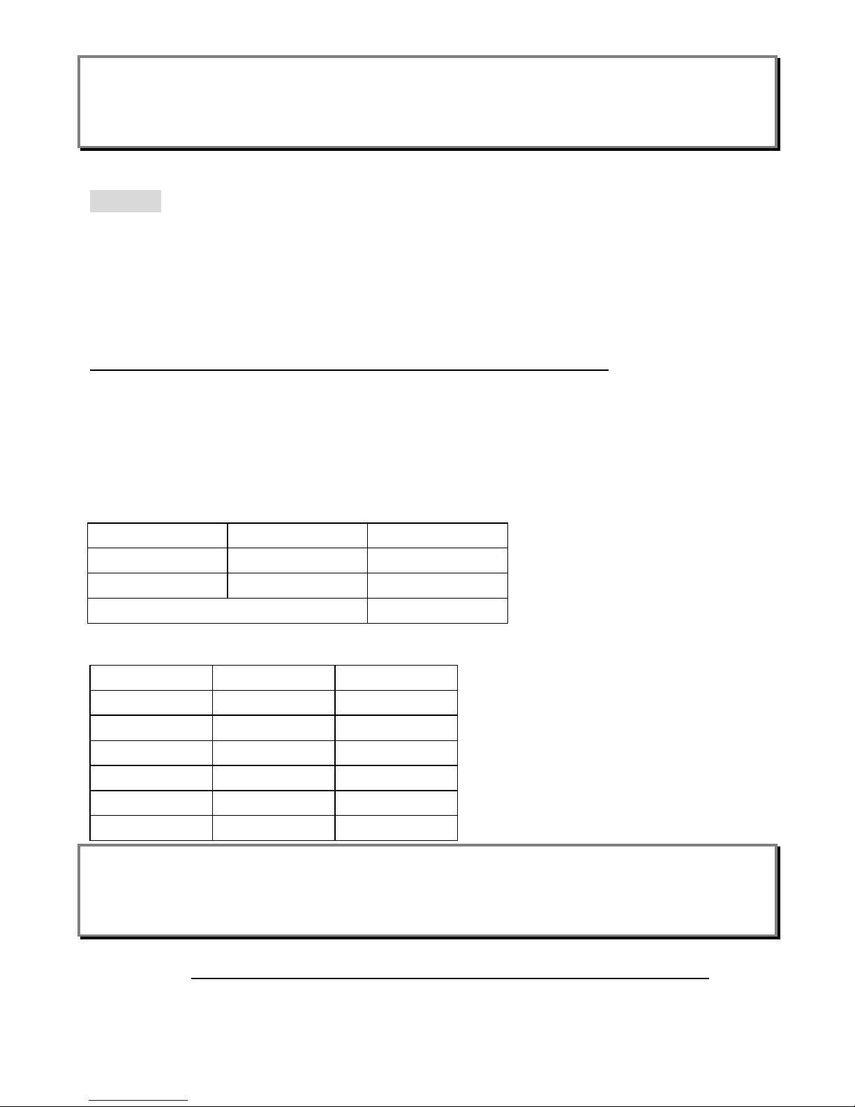
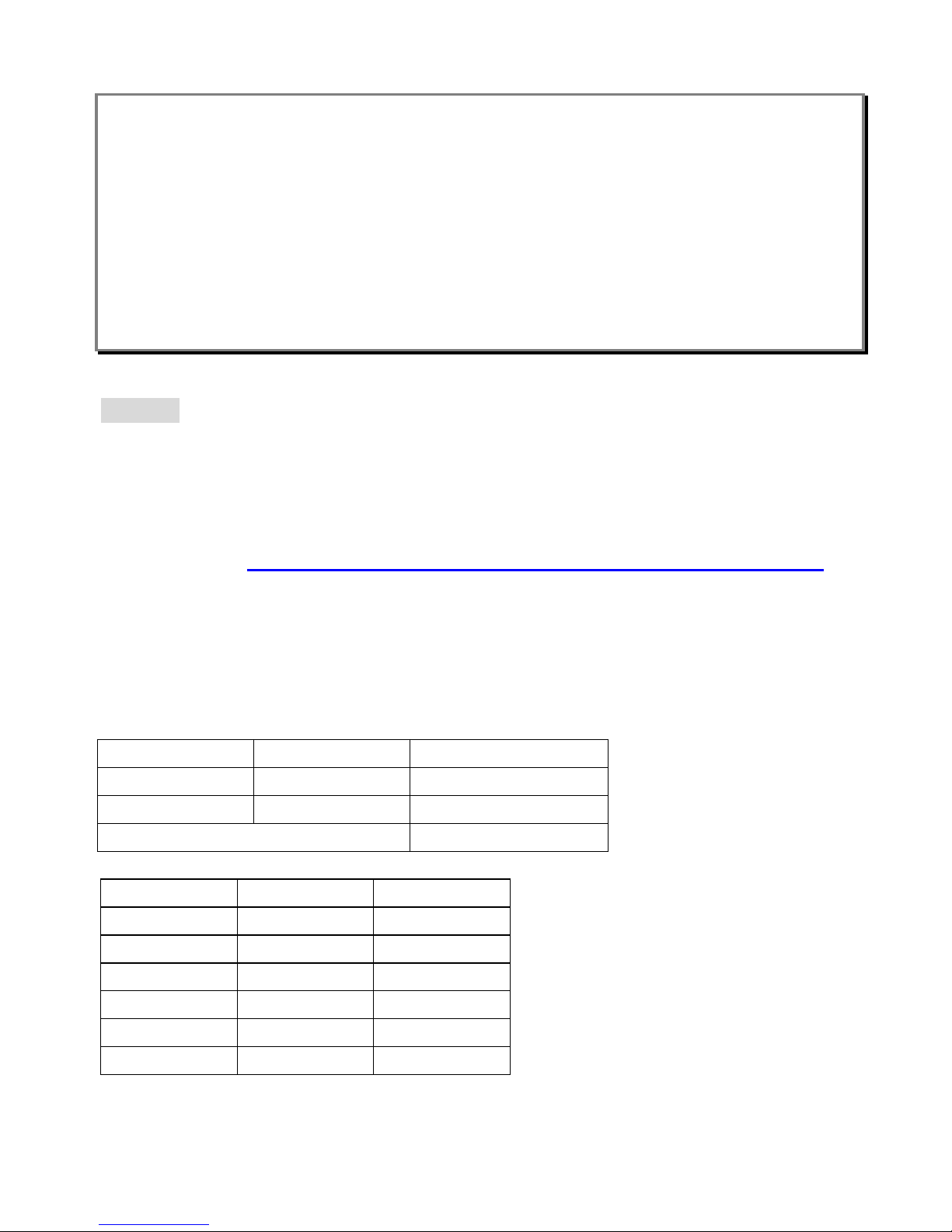
Memory Population Rules
Install at least one DIMM module on the slots. Each DIMM slot supports up to a maximum size of 1GB.
Users can install either single- or double-sided modules to meet their own needs. Please note that each
DIMM can work respectively for single-channel DDR, but there are some rules while using DDR.
Memory modules can be installed in any combination as follows:
Slot Memory Module
Total Memory
DIMM 1 Single/Double side
64MB~1GB
DIMM 2 Single/Double side
64MB~1GB
Maximum System Memory Supported
64MB~2GB
DIMM1 DIMM2 Max Speed
Single x DDR 400
x Single DDR 400
Single Single DDR 400
Single Double DDR 400
Double Single DDR 400
Double Double DDR 333
MSI Reminds You...
The maximum memory speed decreases when both DIMM1 and DIMM2 slots are installed with
double-sided memory module.
Please refer to http://www.msi.com.tw/program/products/mainboard/mbd/pro_mbd_trp_list.php for
compatible DDR modules.
7
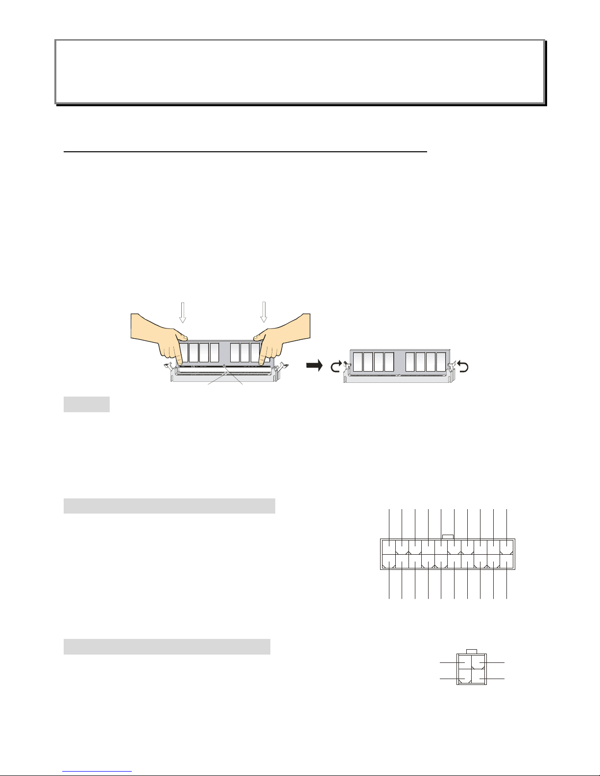
Installing DDR Modules
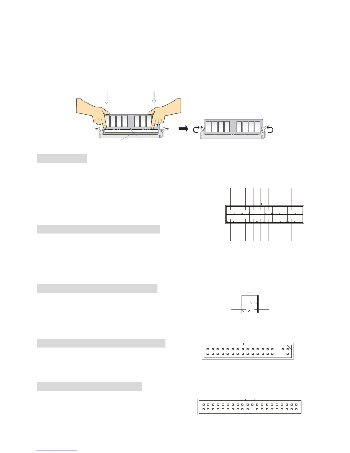
1. The DDR DIMM has only one notch on the center of module. The module will only fit in the right
orientation.
2. Insert the DIMM memory module vertically into the DIMM slot. Then push it in until the golden finger
on the memory module is deeply inserted in the socket.
3. The plastic clip at each side of the DIMM slot will automatically close.
Notch
Volt
Power Supply
The mainboard supports ATX power supply for the power system. Before inserting the power supply
connector, always make sure that all components are installed
properly to ensure that no damage will be caused. Power supplies of
300watt (and up) are highly recommended for system stability.
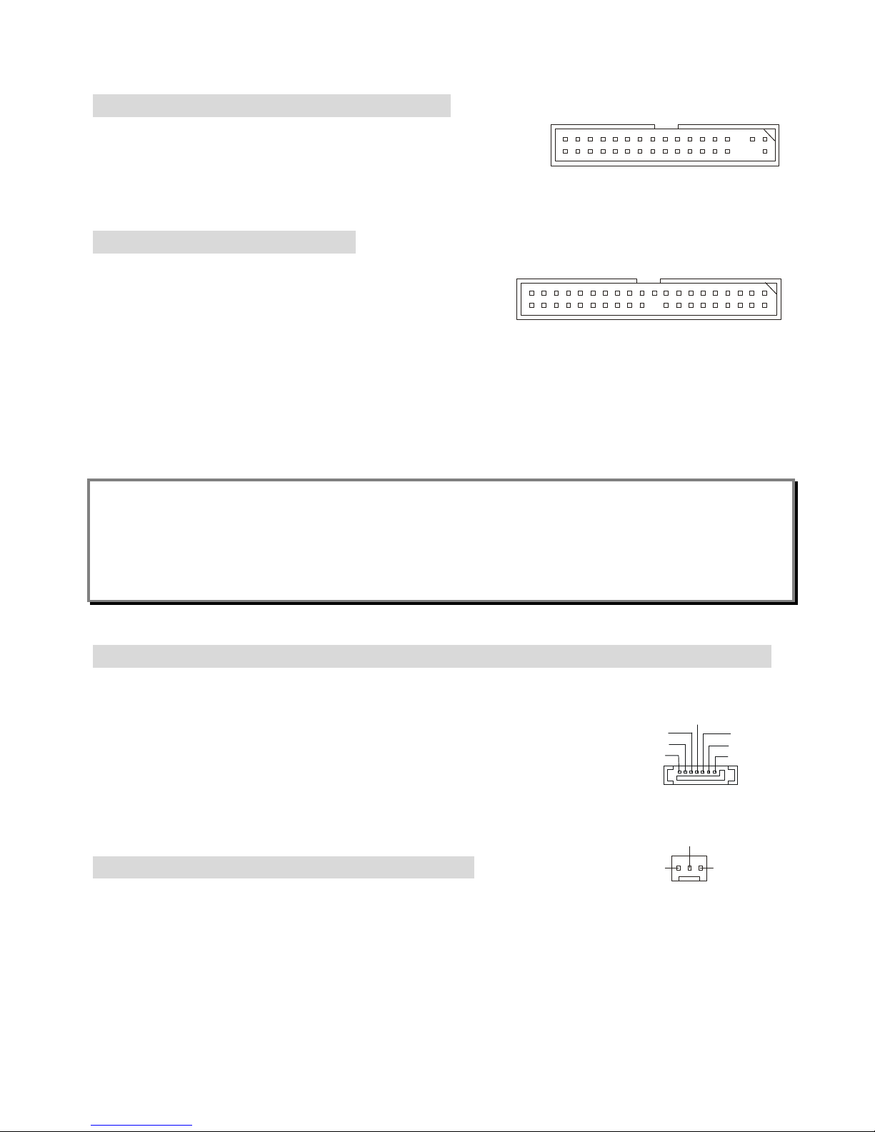
ATX 20-Pin Power Connector: ATX
This connector allows you to connect to an ATX power supply.
To connect to the ATX power supply, make sure the plug of the power supply is inserted in the proper
orientation and the pins are aligned. Then push down the power supply firmly into the connector.
ATX 12V Power Connector: JPW1
This 12V power connector is used to provide power to the CPU.
Floppy Disk Drive Connector: FDD1
The mainboard provides a standard floppy disk drive
connector that supports 360K, 720K, 1.2M, 1.44M and 2.88M floppy disk types.
IDE Connectors: IDE1 & IDE2
The mainboard has a 32-bit Enhanced PCI IDE and Ultra
DMA 33/66/100/133 controller that provides PIO mode
1
11
3.3V
3.3V
3.3V
-12V
GND
GND
GND
GND
GND
GND
GND
PW_OK
-5V
5V_SB
5V
5V
12V
5V
PS_ON
5V
10
20
132
4
GND
GND
12V
12V
8
0~4, Bus Master, and Ultra DMA 33/66/100/133 function. You can connect up to four hard disk drives,
CD-ROM, 120MB Floppy and other devices.
The first hard drive should always be connected to IDE1. IDE1 can connect a Master and a Slave drive.
You must configure second hard drive to Slave mode by setting the jumper accordingly. IDE2 can also
connect a Master and a Slave drive.
MSI Reminds You...
If you install two hard disks on cable, you must configure the second drive to Slave mode by setting its
jumper. Refer to the hard disk documentation supplied by hard disk vendors for jumper setting
instructions.
Serial ATA/Serial ATA RAID Connectors controlled by VT8237/8237R:
SATA1, SATA2
The southbridge VIA VT8237/8237R provides a hybrid solution that combines two independent SATA
ports for support of up to two Serial ATA (Serial ATA RAID) drives and supports
RAID levels 0 or 1 for easy management of the storage subsystems. Both
connectors support 1st generation serial ATA data rate of 150 MB/s and are
fully compliant with Serial ATA 1.0 specifications.
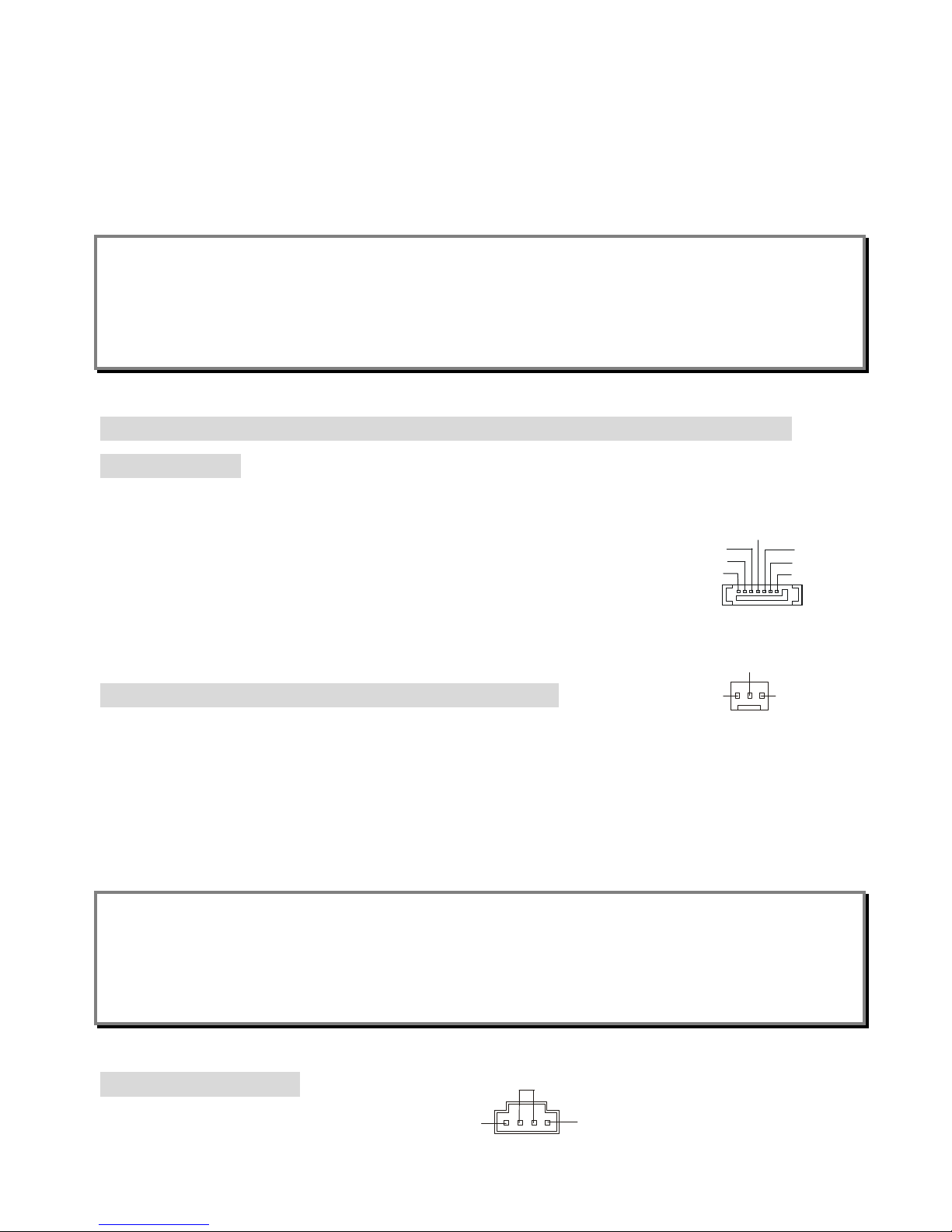
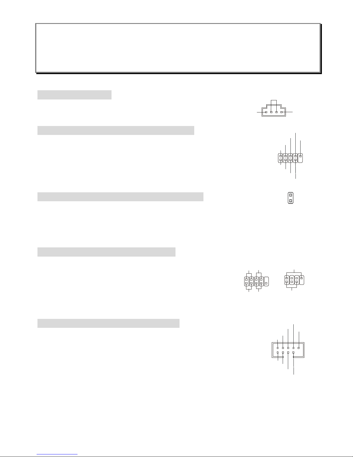
Fan Power Connector: CFAN1/SFAN1/PWFAN1
The CPUFA1 (processor fan) supports system cooling fan with +12V. It supports three-pin head
connector. When connecting the wire to the connectors, always note that the red wire is the positive
and should be connected to the +12V, the black wire is Ground and should be connected to GND. If the
mainboard has a System Hardware Monitor chipset on-board, you must use a specially designed fan
with speed sensor to take advantage of the CPU fan control.
MSI Reminds You...
§ Always consult the vendors for proper CPU cooling fan.
§ CFAN1 supports the fan control. You can install Core Center utility that will automatically control the
CPU fan speed according to the actual CPU temperature.
CD-In Connector: J4
The connector is for CD-ROM audio connector.
+12V
GND
SENSOR
GND
L
R
GND
RXP
RXN
GND
GND
TXP
TXN
17
9
D-Bracket® 2 Connector: JLED1 (Optional)
The mainboard comes with a JLED1 connector for you to connect to D-Bracket® 2.
D-Bracket® 2 is a USB Bracket that supports both USB1.1 & 2.0 spec. It integrates
four LEDs and allows users to identify system problems through 16 various
combinations of LED signals.
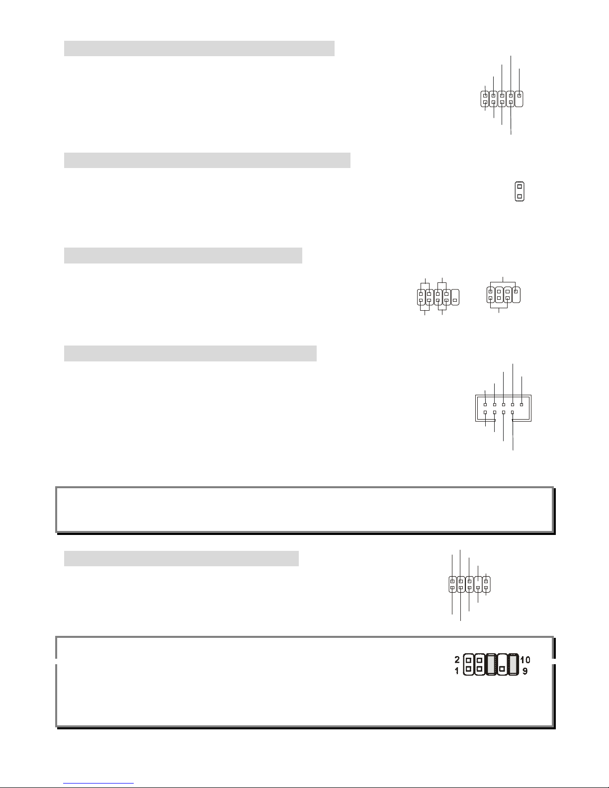
Chassis Intrusion Switch Connector: JCASE1
This connector is connected to a 2-pin chassis switch. If the chassis is opened, the
switch will be short. The system will record this status and show a warning message on
the screen. To clear the warning, you must enter the BIOS utility and clear the record.
Front Panel Connectors: JFP1 & JFP2
The mainboard provides two front panel connectors for electrical
connection to the front panel switches and LEDs. The JFP1 is
compliant with Intel Front Panel I/O Connectivity Design Guide.
Front USB Connectors: JUSB1 & JUSB2
The mainboard provides two USB 2.0 pin headers JUSB1 & JUSB2 that are
compliant with Intel® I/O Connectivity Design Guide. USB 2.0 technology increases
data transfer rate up to a maximum throughput of 480Mbps, which is 40 times faster
than USB 1.1, and is ideal for connecting high-speed USB interface peripherals such
as USB HDD, digital cameras, MP3 players, printers, modems and the like.
MSI Reminds You...
Note that the pins of VCC and GND must be connected correctly, or it may cause some damage.
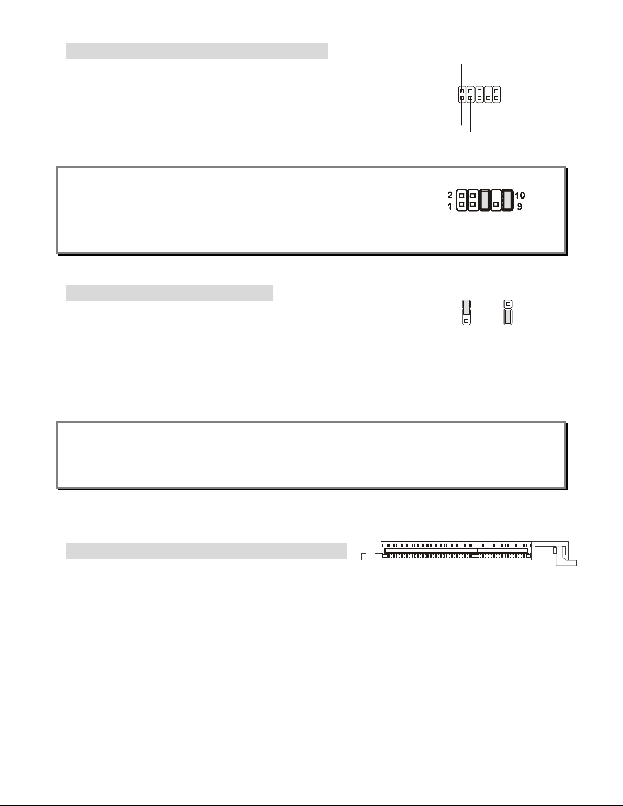
Front Panel Audio Connector: JAUD1
The front panel audio connector allows you to connect to the front panel audio
and is compliant with Intel
®
Front Panel I/O Connectivity Design Guide.
MSI Reminds You...
If you do not want to connect to the front audio header, pins 5 & 6, 9 & 10 have to
be jumpered in order to have signal output directed to the rear audio ports. Otherwise, the Line-Out
connector on the back panel will not function.
Power
LED
Speaker
1
7
2
8
HDD
LED
Power
LED
Reset
Switch
Power
Switch
1
9
2 10
JFP1
JFP2
9
1
2
10
DBR1
DBR2
DBR3
DBR4NCDBG1
DBG2
DBG3
DBG4
1
2
9
10
VCC
USB1-
USB1+
GND
USBOC
VCC
USB0-
USB0+
GND
AUD_FPOUT_L
1
2
9
10
AUD_MIC
AUD_MIC_BIAS
AUD_GND
AUD_VCC
AUD_FPOUT_R
AUD_RET_L
AUD_RET_R
HP_ON
KEY
2
CINTRU
GND
1
10
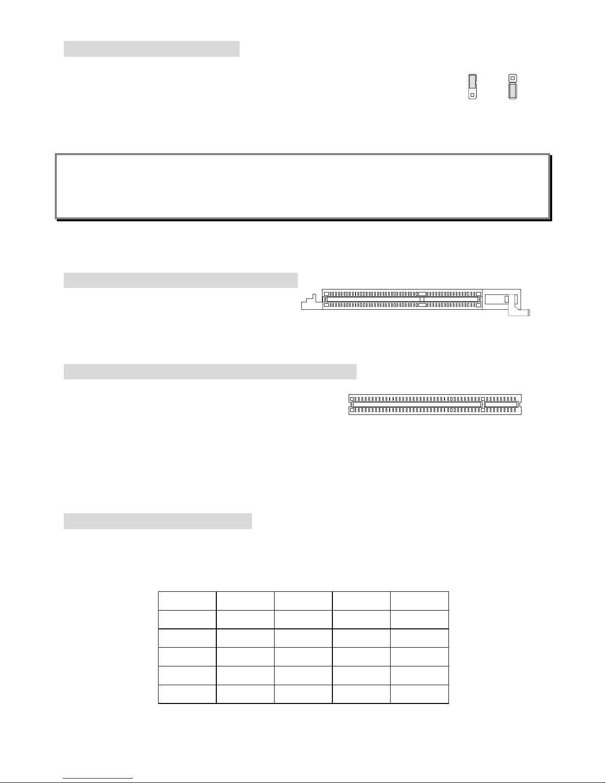
Clear CMOS Jumper: JBAT1
There is a CMOS RAM on board that has a power supply from external battery to
keep the data of system configuration. With the CMOS RAM, the system can
automatically boot OS every time it is turned on. If you want to clear the system
configuration, use the JBAT1 (Clear CMOS Jumper) to clear data.
MSI Reminds You...
You can clear CMOS by shorting 2-3 pin while the system is off. Then return to 1-2 pin position. Avoid
clearing the CMOS while the system is on; it will damage the mainboard.
The mainboard provides one AGP slot and five 32-bit PCI bus slots.
AGP (Accelerated Graphics Port) Slot
The AGP slot allows you to insert the AGP
graphics card. AGP is an interface specification
designed for the throughput demands of 3D graphics. It introduces a 66MHz, 32-bit channel for the
graphics controller to directly access main memory. The slot supports 8x/4x AGP card.
PCI (Peripheral Component Interconnect) Slots
The PCI slots allow you to insert the expansion cards to
meet your needs. When adding or removing expansion
cards, make sure that you unplug the power supply first. Meanwhile, read the documentation for the
expansion card to make any necessary hardware or software settings for the expansion card, such as
jumpers, switches or BIOS configuration.
The orange PCI slot (PCI5) also works as a communication slot, which allows you to insert the
communication card, such as the wireless LAN PCI cards of MSI.
PCI Interrupt Request Routing
The IRQ, acronym of interrupt request line and pronounced I-R-Q, are hardware lines over which
devices can send interrupt signals to the microprocessor. The PCI IRQ pins are typically connected to
the PCI bus INT A# ~ INT D# pins as follows:
Order 1 Order 2 Order 3 Order 4
PCI Slot 1
INT A# INT B# INT C# INT D#
PCI Slot 2
INT B# INT C# INT D# INT A#
PCI Slot 3
INT C# INT D# INT A# INT B#
PCI Slot 4
INT D# INT A# INT B# INT C#
PCI Slot 5
INT B# INT C# INT D# INT A#
1
3
Keep Data
Clear Data
1
3
11
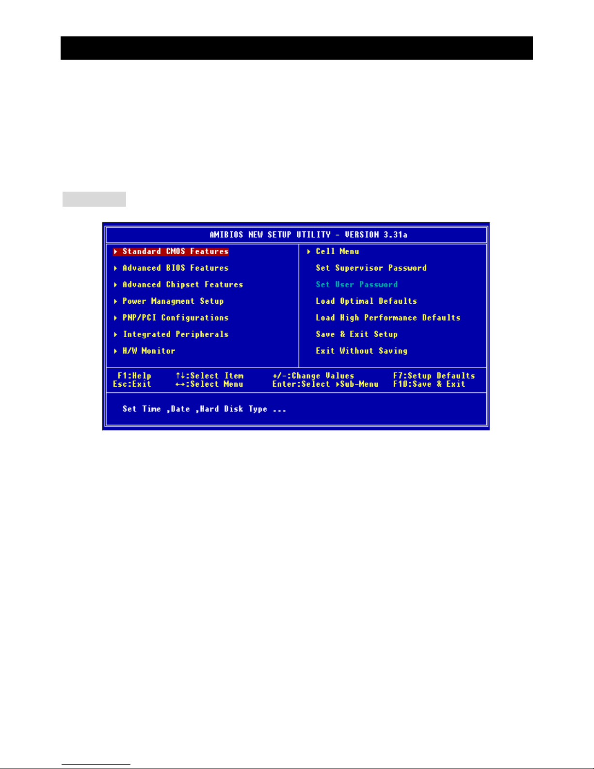
BIOS Setup
Power on the computer and the system will start POST (Power On Self Test) process. When the
message below appears on the screen, press <DEL> key to enter Setup.
DEL: Setup F11: Boot Menu F12: Network boot TAB: Logo
If the message disappears before you respond and you still wish to enter Setup, restart the system by
turning it OFF and On or pressing the RESET button. You may also restart the system by
simultaneously pressing <Ctrl>, <Alt>, and <Delete> keys.
Main Page
Standard CMOS Features
Use this menu for basic system configurations, such as time, date etc.
Advanced BIOS Features
Use this menu to setup the items of AMI special enhanced features.
Advanced Chipset Features
Use this menu to change the values in the chipset registers and optimize your system performance.
Power Management Features
Use this menu to specify your settings for power management.
PNP/PCI Configurations
This entry appears if your system supports PnP/PCI.
Integrated Peripherals
Use this menu to specify your settings for integrated peripherals.
H/W Monitor
Use this menu to specify your settings for hardware.
Cell Menu
Use this menu to specify your settings for CPU/AGP frequency/voltage control and overclocking.
Load Optimal Defaults

12
Use this menu to load the factory default settings for optimal & stable system performance.
Load High Performance Defaults
Use this menu to load the BIOS values for the best system performance, but the system stability may
be affected.
Cell Menu
Cool’n’Quiet Support
This item enables or disables the Cool’n’Quiet Function. Cool’n’Quiet is a special feature designed
only for AMD Athlon64 processor, and with Cool’n’Quiet, the system will be capable of detecting the
system working status. When the system is idle for a certain time, the CPU clock will decrease
automatically, and once the system is waken up, the CPU clock will return to its previous status.
Setting options: [Enabled], [Disabled]. Note that for the purpose of ensuring the stability of
Cool’n’Quiet function, it is always recommended to have the memories plugged in DIMM1.
Spread Spectrum
When the motherboard clock generator pulses, the extreme values (spikes) of the pulses creates EMI
(Electromagnetic Interference). The Spread Spectrum function reduces the EMI generated by
modulating the pulses so that the spikes of the pulses are reduced to flatter curves. If you do not have
any EMI problem, leave the setting at [Disabled] for optimal system stability and performance. But if you
are plagued by EMI, set to [Enabled] for EMI reduction. Remember to disable Spread Spectrum if you
are overclocking because even a slight jitter can introduce a temporary boost in clock speed which may
just cause your overclocked processor to lock up.
Stop Unused PCI Slot Clock
This item enables or disables the PCI slot clock. Setting options: Disabled, Enabled.

13
CPU Ratio
This item lets you to adjust the CPU ratio. Setting options are: [Startup], [4x]~[11x].
Dynamic Overclocking
Dynamic Overclocking Technology is the automatic overclocking function, included in the MSITM newly
developed CoreCellTM Technology. It is designed to detect the load balance of CPU while running
programs, and to adjust the best CPU frequency automatically. When the motherboard detects that the
CPU is running programs, it will speed up CPU automatically to make the program run smoothly and
faster. When the CPU is temporarily suspending or staying in the low load balance, it will restore the
default settings instead. Usually the Dynamic Overclocking Technology will be powered only when
users' PC need to run huge amount of data like 3D games or the video process, and the CPU frequency
needs to be boosted up to enhance the overall performance.
Setting options:
[Disabled] Disable Dynamic Overclocking.
[Private] 1st level of overclocking.
[Sergeant] 2nd level of overclocking.
[Captain] 3rd level of overclocking, also the default value of "Load High Performance
Defaults".
[Colonel] 4th level of overclocking.
[General] 5th level of overclocking.
[Commander] 6th level of overclocking.
MSI Reminds You...
1. Even though the Dynamic Overclocking Technology is more stable than manual overclocking,
basically, it is still risky. We suggest that users make sure that the CPU can afford to overclocking
regularly first. If you find the PC appears to be unstable or reboot incidentally, it's better to disable the
Dynamic Overclocking or to lower the level of overclocking options. By the way, if you need to
conduct overclocking manually, you also need to disable the Dynamic OverClocking first.
2. Meanwhile, there are two functions to protect user's system from crashing.
- There is a safe key "Ins" in BIOS. In case the overclocking fails, you can press "Ins" key while
system rebooting to restore to the BIOS defaults.
- If the system incidentally reboot for four times, the BIOS will also be restored to the defaults.
CPU FSB Clock
This setting shows the current CPU Front Side Bus clock frequency.
DRAM Clock Mode
This item enables or disables the function of configuring the clock frequency of the installed DRAM.
Settings: [Enabled], [Disabled].

14
DRAM Clock
If DRAM Clock Mode is set to [Enabled], use this field to configure the clock frequency of the installed
DRAM. Settings: DDR 200, DDR 266, DDR 300, DDR 333, DDR 400.
AGP Voltage (V)
AGP voltage is adjustable in the field, allowing you to increase the performance of your AGP display
card when overclocking, but the stability may be affected.
DRAM Voltage (V)
This setting is used to adjust the DRAM core voltage (Vcore), making overclocking possible.
MSI Reminds You...
The settings shown in different color in AGP Voltage, and DRAM Voltage help to verify if your setting is
proper for your system.
White: Safe setting.
Yellow: High performance setting.
Red: Not recommended setting and the system may be unstable.
Changing CPU/DDR/AGP/North Bridge/South Bridge Voltage may result in system instability; therefore,
it is NOT recommended to change the default settings for long-term usage.
For complete BIOS setup information, please visit MSI website at http://www.msi.com.tw

15
Einleitung
Vielen Dank für die Wahl des MS-7032 (K8T Neo-V/K8M Neo-V) v1.X ATX Mainboards. Das K8T
Neo-V/K8M Neo-V basiert auf dem VIA® K8T800/K8M800 North Bridge & VT8237/8237R South Bridge
Chipsatz und ist mit USB 2.0 Anschlüssen Anschlüsse für schnellen Datentransfer ausgestattet und hat
einen RealTek ALC655 Audio-Chip mit 6-Kanal-Ausgang. Entwickelt für AMD® K8 Athlon64
Prozessoren, bietet das K8T Neo-V/K8M Neo-V Mainboard hohe Performance und eine professionelle
Desktop Platform Lösung.
Layout
SFAN1CFAN1JPW
1
PW FAN1
FDD1
SATA2
SATA1
J
4
T:
M:
B:
Line-In
Line-Out
Mic
T: LAN jack
B: USB ports
WinbondW83627TH
F
VIA
K8T800
or
K8M800
AGP Slot
BATT
+
VT8237
DDR 1DDR
2
ATXPower Supply
PCI Slot 5
PCI Slot 4
PCI Slot 3
PCI Slot 2
PCI Slot 1
IDE 2
IDE 1
JFP1
JBAT1
JCASE1
JFP2
JLED
JAUD1
JUSB2JUSB1
Top : Parallel Port
Bottom:
COM A
VGA Port (For K8M Neo-V only)
Top : mouse
Bottom: keyboard
USB port
Core C
ell
BIO
S
Codec
RTL8201CL

16
Spezifikationen
CPU
l Unterstützt 64-bit AMD® K8 Athlon64 Prozessor (Socket 754)
l Unterstützt bis zu 2800+, 3000+, 3100+, 3200+, 3400+, 3700+, oder schnellere CPU
(Für die neuesten CPU-Kompatiblitäts-Informationen besuchen Sie bitte die folgende Webseite:
http://www.msi.com.tw/program/products/Mainboard/mbd/pro_mbd_cpu_support.php )
Chipsatz
l VIA® K8T800 / K8M800 Chipsatz
- HyperTransportTM verbindung zu AMD Athlon64 Prozessor
- 8 oder 16 bit Control/Address/Data Transfer in beiden Richtungen
- 800/600/400/200 MHz “Double Data Rate” Operation in beide Richtungen
- AGP v3.0 kompatibel mit 8x Transfer Modus
l VIA® VT8237/8237R Chipsatz (487 BGA)
- Integrierter Faster Ethernet LPC
- Integrierter Hardware Sound Blaster/Direct Sound AC97 Audio
- Ultra DMA 33/66/100/133 Master Modus PCI EIDE Kontroller
- Unterstützt 2 Serial ATA RAID0/1
- Unterstützt 8 USB2.0 Anschlüsse
Hauptspeicher
l Unterstützt DDR266/333/400 DDR SDRAM für zwei 184-Pin DDR DIMMs
l Unterstützt eine maximale Speichergröße von 2GB
(Für die neuesten Speicher-Kompatiblitäts-Informationen besuchen Sie bitte die folgende Webseite:
http://www.msi.com.tw/program/products/Mainboard/mbd/pro_mbd_trp_list.php )
Steckplätze
l Ein (Accelerated Graphics Port) AGP Steckplatz (Entspricht der AGP 3.0 Spezifikation)
l Fünf 32-Bit Master 3.3v / 5v PCI Bus Steckplätze
On-Board IDE
l Ein IDE Kontroller im VIA® VT8237/8237R Chipsatz unterstützt IDE HDD/CD-ROM mit PIO, Bus
Master und Ultra DMA 33/66/100/133 Betriebsmodus
l Es können bis zu 4 IDE Laufwerke angeschlossen werden
l Serial ATA/150 Kontroller integriert in VT8237/8237R
- Bis zu 150MB/s Transferrate

17
- Es können bis zu zwei Serial ATA Laufwerke mit RAID0 & RAID1 angeschlossen werden.
On-Board Peripherie
l On-Board Peripherie beinhaltet:
- 1 Floppyanschluss für bis zu 1 FDD mit 360K, 720K, 1.2M, 1.44M und 2.88Mbytes
- 1 serieller Anschluss (COMA)
- 1 paralleler Anschluss, unterstützt SPP/EPP/ECP Modus
- 1 Audio Anschluss
- 1 D-Bracket2 Anschluss
- 1 RJ-45 LAN Anschluss
- 8 USB Anschlüsse (Vorne x 4 / Rückseite x 4)
- 1 VGA Anschluss (Nur bei K8M Neo-V)
Audio
l 6 Kanal Software Audio Codec RealTek ALC655.
- Entspricht der AC97 v2.3 Spezifikation
- Entspricht den PC2001 Audio Performance Anforderungen
LAN
l 10/100Mbps Realtek® 8201CL
l Gigabit Ethernet LAN Realtek® 8110SB (optional)
- Fast Ethernet MAC und PHY in einem Chip.
- Beide entsprechen den PCI V2.2 Spezifikationen.
- Beide unterstützn ACPI Power Management.
BIOS
l Das Mainboard BIOS stellt “Plug & Play” BIOS-Funktionen zur Verfügung, welche Periphie-Geräte
und Erweiterungskarten beim Systemstart automatisch erkennen.
l Das Mainboard hat eine Desktop Management Interface (DMI) Funktion, welche die Konfiguration
des PCs speichert.
Größe
l ATX Form Faktor: 305 mm (L) x 210 mm (B).
Befestigung
l 6 Befestigungslöcher.
18
Anschlüsse auf der Rückseite
Folgende Anschlüsse stehen auf der Rückseite zur Verfügung:
Mouse
Keyboard
Parallel
COM A VGA Port
(For K8M Neo-V only)
USB Ports
LAN
L-in
L-out
MIC
Hardware Einrichtung
Dieses Kapitel beschreibt Ihnen, wie CPU, Speichermodule und Erweiterungskarten eingesetzt werden,
und wie Jumper auf dem Mainboard eingestellt werden. Es beinhaltet auch die Anleitung, wie Sie
Peripheriegeräte wie Maus, Tastatur, usw. anschließen. Während der Installation behandeln Sie bitte
die Komponenten vorsichtig und folgen Sie genau der Anleitung.
Prozessor
Das Mainboard unterstützt AMD® Athlon64 Prozessoren. Dafür hat es einen CPU Sockel 754 für eine
einfache CPU Installation. Um den Prozessor vor Überhitzung zu schützen, stellen Sie sicher, dass Sie
einen geeigneten CPU-Kühler mit Lüfter auf dem Prozessor installieren.. Wenn Sie keinen geeigneten
Kühler für Ihren Prozessor haben sollten, kontaktieren Sie Ihren Händler, um ein passendes Modell
erwerben. Bitte schalten Sie den PC nicht ein, wenn Sie keinen geeigneten Kühler installiert haben.
(Für die neuesten CPU-Kompatiblitäts- Informationen besuchen Sie bitte die folgende Webseite:
http://www.msi.com.tw/program/products/Mainboard/mbd/pro_mbd_cpu_support.php )
Speichertakt / ext. CPU Takt Tabelle
Speicher
DDR 266 DDR333 DDR400
FSB200 OK OK OK
FSB

19
Installation der CPU im Sockel 754
1. Bitte schalten Sie den Computer aus und trennen ihn von der Netzspannung, bevor Sie die CPU
einsetzen.
2. Klappen Sie den seitlichen Hebel im 90° Winkel nach Oben.
3. Die dreieckige Markierung auf dem Prozessor muss so ausgerichtet werden, dass sie wie ein
Pfeil auf das Lager des Verriegelungshebel zeigt. Nur in dieser Richtung passt der Prozessor in
den Sockel.
4. Wenn die CPU richtig eingesetzt wurde, sind die Anschlüsse der CPU komplett in den Sockel
versunken und könnne nicht mehr gesehen werden, Bitte beachten Sie, dass beim falschen
Eisetzen der CPU in den Sockel das Mainboard und die CPU zerstört werden können!
5. Drücken Sie nochmal auf die CPU und klappen dabei den Hebel wieder herunter, bis er einrastet.
Dabei bewegt sich die CPU noch etwas in ihre endgültige Position.
Installing AMD Athlon64 CPU Cooler Set
Da die Prozessor Technologie rasante Fortschritte zu höherern Taktraten und mehr Performacne macht,
wird die Kühlung des Prozessors immer wichtiger. Um den Prozessor ausrechend zu kühlen, müssen
Sie einen geeigneten CPU Kühler auf die CPU aufsetzen. Bitte folgen Sie der nachfolgenden Anleitung,
um den Kühler korrekt zu installieren:
1. Nehmen Sie die Schutzfolie von der Metallplatte ab.
2. Drehen Sie das Mainboard so, dass die Rückseite nach oben zeigt und bringen Sie die
Metallplatte in die richtige Position und drücken Sie sie an. Die beiden Gewindebolzen der Platte
müssen durch die Löcher um den Prozessorsockel gesteckt werden.
3. Drehen Sie das Mainboard wieder so, dass die Komponentenseite oben ist. Sie sollten nun vor
und hinter dem Sockel die Gewindebolzen der Metallplatte sehen.
4. Legen Sie den Retension-Mechanismus deckungsgleich mit der Metallplatte auf das Mainboard
und verschrauben beide Teile miteinander.
5. Setzen Sie den Kühler auf den Retension-Mechanismus auf und haken den Kühler erst auf der
einen, und dann auf der anderen Seite am Retension-Modul ein.
6. Der Kühler hat einen Befestigungshebel, einen Bolzen und einen Befestigungshaken. Klappen
Sie den Hebel hoch.
7. Klappen Sie den Hebel wieder herunter, und achten darauf, dass der Befestigungshaken in den
Bolzen des Retension-Moduls eingreift.
8. Schliessen Sie das Kabel des CPULüfter an dem CPU-Lüfteranschluss des Mainboards an.
20
MSI erinnert Sie...
Überhitzung…
Überhitzung beschädigt Ihre CPU und ds gesamte System ernsthaft, stellen Sie daher sicher, dass die
Lüfter immer funktionieren, um die CPU und das System vor Schäden zu bewahren.
Die CPU tauschen…
Wenn Sie die CPU tauschen, schalten Sie das System ab und ziehen den Netzstecker. Bevor Sie das
Mainboard oder die CPU anfassen, erden Sie sich, in dem Sie kurz geerdeten Gegenstand (z.B.
Heizung) berühren. Dadurch vermeiden Sie Defekte an der Hardware durch statische Aufladung.
Memory
Das Mainboard hat 2 Steckplätze für 184-Pin DDR SDRAM DIMM (Double In-Line Memory Modul)
Module und unterstützt eine Spüeichergöße bis zu 2GB. Sie können PC3200/DDR400,
PC2700/DDR333, oder PC2100/DDR266 unbuffered DIMM Module in den DDR DIMM Steckplätzen
(DDR 1~2) installieren. (Für die neuesten Speicher-Kompatiblitäts-Informationen besuchen Sie bitte die
folgende Webseite: http://www.msi.com.tw/program/products/mainboard/mbd/pro_mbd_trp_list.php )
Speicherbestückung
Installieren Sie mindestens ein DIMM Module auf den Steckplätzen. Jeder DIMM Steckplatz unterstützt
bis zu einer Maximalen Größe von 1GB. Sie können sowohl einseitige als auch doppelseitige Module
nach Ihren Anforderungen einsetzen. Einkanal-Betrieb funktioniert.
Steckplatz Speichermodul Gesamt-Speichergröße
DIMM 1 Ein/Doppelseitig
64MB~1GB
DIMM 2 Ein/Doppelseitig
64MB~1GB
Gesamtspeicher des Systems 64MB~2GB
DIMM1 DIMM2 Max Speed
Single x DDR 400
x Single DDR 400
Single Single DDR 400
Single Double DDR 400
Double Single DDR 400
Double Double DDR 333
21
MSI Reminds You...
Die maximale Speicherzugriffsgeschwindigkeit sinkt, wenn auf DIMM1 und DIMM2 jeweils
doppelseitige Speichermodule installiert werden.
Um den letzten Stand bezű lich der unterstű zten Speichermodule zu erhalten, besuchen Sie bitte
http://www.msi.com.tw/program/products/mainboard/mbd/pro_mbd_trp_list.php
DDR Modules einsetzen
1. Das DDR DIMM Modul hat in der Mitte eine Nase, die verhindern soll, dass Sie das Modul in der
falschen Richtung einsetzen.
2. Setzen Sie das Modul senkrecht in den Sockel ein, bis die goldenen Kontakte komplett im Sockel
versinken.
3. Die weißen Verriegelungshebel an der Seite schließen sich automatisch und rasten ein.
Notch
Volt
Netzteil
Das Mainboard unterstützt ATX Netzteile für die Stromversorgung. Befor Sie das System einschalten,
vergewissern Sie sich, dass alle Komponenten richtig eingesetzt wurden, damit das System nicht
beschädigt werden kann.. Ein Netzteil mit 300W oder mehr wird empfohlen.
ATX 20-Pin Power Connector: ATX
This connector allows you to connect to an ATX power supply. To
connect to the ATX power supply, make sure the plug of the
power supply is inserted in the proper orientation und the pins
are aligned. Then push down the power supply firmly into the
connector.
ATX 12V Power Anschluss: JPW1
Dieser 12V Stromanschluss versorgt die CPU mit Strom. Auch dieser
Stecker lässt sich nur in eine Richtung einsetzen..
132
4
GND
GND
12V
12V
1
11
3.3V
3.3V
3.3V
-12V
GND
GND
GND
GND
GND
GND
GND
PW_OK
-5V
5V_SB
5V
5V
12V
5V
PS_ON
5V
10
20
22
Floppy Disk Laufwerk Anschluss: FDD1
Das Mainboard stellt einen Floppyanschluss zur Verfügung, an
dem bis zu zwei Lauf werke mit 360K, 720K, 1.2M, 1.44M und
2.88M Kapazität angeschlossen werden können.
IDE Anschlüsse: IDE1 & IDE2
Das Mainboard hat einen 32-Bit erweiterten PCI IDE und
Ultra DMA 33/66/100/133 Kontroller, welcher die PIO Modis
0~4, Bus Master, und Ultra DMA 33/66/100/133 unterstützen.
Sie können bis zu vier Festplatten, CD-ROM, 120MB Floppy oder andere Gerägte anaschliessen.
Das erste Laufwerk sollte immer an IDE1 angeschlossen werden. An IDE1 und IDE2 kann jeweils ein
Master und ein Slave Laufwerk angeschlossen werden. Die Einstellung für Master und Slave muss an
dem Laufwerk mit einem Jumper festgelegt werden.
MSI erinnert Sie...
Wenn Sie zwei IDE-Laufwerke an einem IDE-Kabel anschließen, so müssen Sie das erste Laufwerk
als Master und das zweite Laufwerk als Slave konfigurieren. Sie erfahren aus der Dokumentation der
Laufwerke, wie diese Einstellung gemacht wird.
Serial ATA/Serial ATA RAID Anschlüsse des VT8237/8237R: SATA1, SATA2
Die Southbridge VIA VT8237/8237R stellt zwei unabhängige SATA Anschlüsse für den Anschluss von
bis zu zwei Serial ATA (Serial ATA RAID) Laufwerke zur Verfügung und
unterstützt die RAID Levels 0 oder 1 für mehr Performance oder Sicherheit.
Beide Anschlüsse unterstützen die erste Generation von Serial ATA mit einer
Datenrate von 150 MB/s und enstprechen vollständig der Serial ATA 1.0 Spezifikation.
Lüfteranschlüsse: CFAN1/SFAN1/PWFAN1
Der CPUFA1 (Prozessorlüfter) unterstützt Lüfter mit einer Betriebsspannung von +12V mit einem
dreipoligen Anschluss der auch die Lüfterüberwachung zulässt. Bitte beachten Sie, dass der Lüfter
nicht verpolt wird, das rote Kabel des Lüftersteckers muss an 12V, das schwazer an GND (Masse)
angeschlossen werden. Der dritte Pol des Steckers übermittelt das Tachosignal an den System
Hardware Monitor Chipsatz auf dem Mainboard.
+12V
GND
SENSOR
GND
RXP
RXN
GND
GND
TXP
TXN
17
23
MSI Reminds You...
§ Bitte die Herstellerhinweise des Prozessorherstellers bezüglich passendem Kühler beachten.
§ CFAN1 unterstützt eine Drehzahlregelung des Lüfters. Mit dem Programm Core Center auf der
beiliegenden CD wird die Lüfterdrehzahl anhand der CPU-Temperatur geregelt.
CD-In Anschluss: J4
Hier können Sie das Audiokabel Ihres CD-Laufwerks anschließen.
D-Bracket® 2 Anschluss: JLED1 (Optional)
Das Mainboard hat den Anschluss JLED1 für die Verwendung des D-Bracket® 2.
Das D-Bracket® 2 ist ein USB Bracket welches die USB1.1 und 2.0 Spezifikation
unterstützt. Außerdem sind darin vier LEDs integriert, die die Systemdiagnose beim
Start des PCs mit 16 verschiedenen Farbkombinationen der LED anzeigen.
Chassis Intrusion Switch Connector: JCASE1
This connector is connected to a 2-pin chassis switch. If the chassis is opened, the
switch will be short. The System will record this status und show a warning message on the screen. To
clear the warning, you must enter the BIOS utility und clear the record.
Front Panel Anschlusss: JFP1 & JFP2
Das Mainboard hat Anschlüsse für Bedienelemente und Statusanzeigen
an der Vorderseite des gehäuses. Hierzu gehören Anzeige LEDs und
Taster. JFP1 entspricht dem “Intel Front Panel I/O Connectivity Design
Guide“.
Front USB Anschlüsse: JUSB1&JUSB2
Das Mainboard stellt einen UHCI (Universal Host Controller Interface) Universal
Serial Bus Kontroller für den Anschluß von USB Geräten wie Tastatur, Maus und
andere USB kompatible Geräte zur Verfügung Stecken Sie an diese
Anschlüsse den Adapter mit den üblichen USB-Steckern an.
Power
LED
Speaker
1
7
2
8
HDD
LED
Power
LED
Reset
Switch
Power
Switch
1
9
2 10
JFP1
JFP2
1
2
9
10
VCC
USB1-
USB1+
GND
USBOC
VCC
USB0-
USB0+
GND
2
CINTRU
GND
1
GND
L
R
9
1
2
10
DBR1
DBR2
DBR3
DBR4NCDBG1
DBG2
DBG3
DBG4
24
Gehäusefront Audio-Anschluss: JAUD1
Der JAUD1 Gehäusefront-Anschluss erlaubt es Ihnen, Audio-Anschlüsse
an der Vorderseite Ihres Gehäuses mit dem Mainboard zu verbinden. Der
Anschluss entspricht dem “Intel ® Front Panel I/O Connectivity Design
Guide”
MSI erinnert Sie...
Wenn Sie diesen Audioanschluss nicht verwenden möchten, so müssen die
Kontakte 5 & 6, 9 & 10 jeweils mit einem Jumper geschlossen sein, damit der hintere Audio-Ausgang
des Mainboards funktioniert..
CMOS Rücksetz-Jumper: JBAT1
Im Mainboard ist ein CMOS Speicher integriert, welches von einer Batterie
versorgt wird, um die Systemkonfiguration zu speichern. Das CMOS RAM
ermöglicht es, das System automatisch zu starten, ohne dass die Konfiguration neu eingestellt werden
muss. Wenn Sie die CMOS-Konfiguration löschen wollen, setzen Sie im ausgeschalteten Zustand den
Jumper JBAT1 von Position 1-2 auf 2-3 um.
MSI erinnert Sie...
Schalten Sie den PC vor dem Umsetzen des Jumpers aus. Setzen Sie den Jumper nach ein paar
Sekunden wieder in 1-2 zurück und schalten erst dann den PC wieder ein.
The Mainboard provides one AGP slot und five 32-bit PCI bus Steckplätze.
AGP (Accelerated Graphics Port) Steckplatz
In den AGP Steckplatz können Sie eine AGP-Grafikkarte einsetzen. AGP ist eine Schnittstelle, deren
Spezifikation für den Datendurchsatz von schnellen 3D-Grafuikkarten entwickelt wurde. AGP
ermöglicht 66MHz, 64-Bit Datenübertragung für den Grafik-Kontroller direkt zum Hauptspeicher. Das
Mainboard unterstützt AGP-Grafikkarten mit 4x/8x Übertragung.
AUD_FPOUT_L
1
2
9
10
AUD_MIC
AUD_MIC_BIAS
AUD_GND
AUD_VCC
AUD_FPOUT_R
AUD_RET_L
AUD_RET_R
HP_ON
KEY
1
3
Keep Data
Clear Data
1
3
 Loading...