

MSI K8NNeo2-FX, MS-7025 User Manual
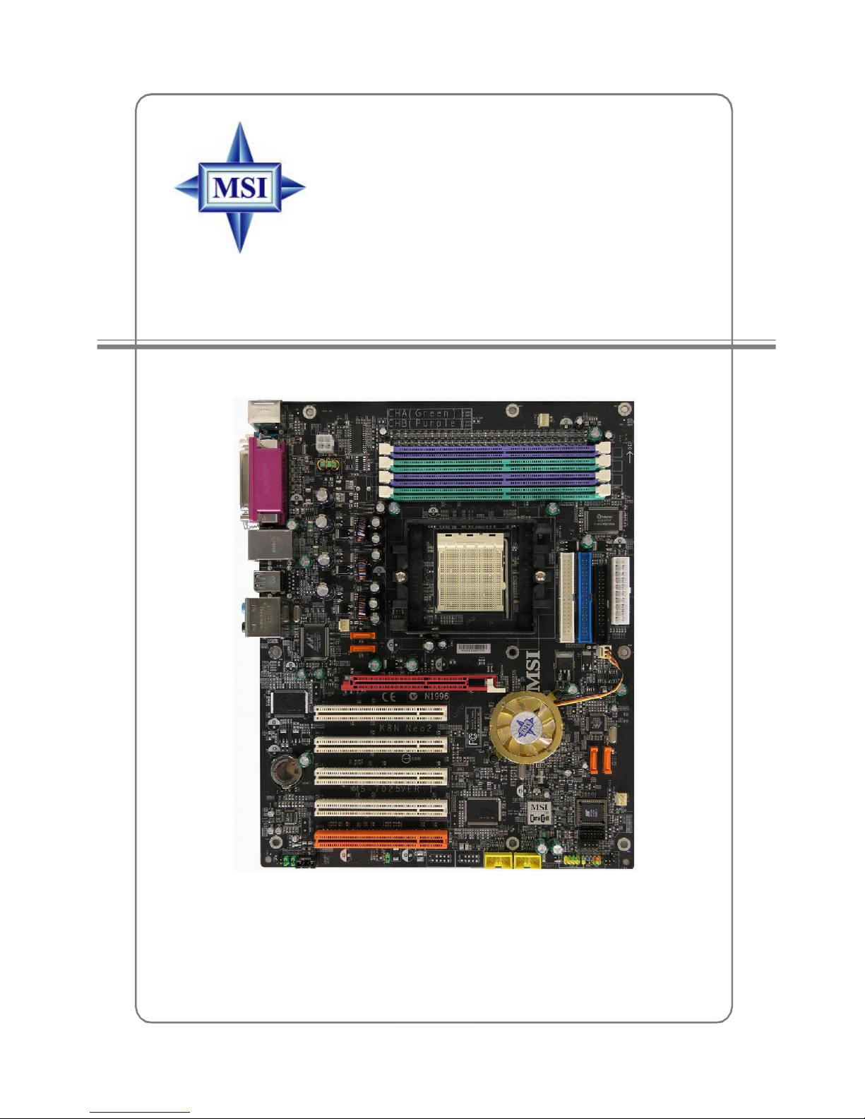
K8N Neo2-FX Series
MS-7025 (v1.X) ATX Mainboard
English / French / German
Version
G52-M7025XC
i
Manual Rev: 1.4
Release Date: Mar, 2005
FCC-B Radio Frequency Interference Statement
This equipment has been tested and found to comply with the limits for a class B
digital device, pursuant to part 15 of the FCC rules. These limits are designed to
provide reasonable protection against harmful interference when the equipment is
operated in a commercial environment. This equipment generates, uses and can
radiate radio frequency energy and, if not installed and used in accordance with the
instruction manual, may cause harmful interference to radio communications. Operation
of this equipment in a residential area is likely to cause harmful interference, in which
case the user will be required to correct the interference at his own expense.
Notice 1
The changes or modifications not expressly approved by the party responsible for
compliance could void the user’s authority to operate the equipment.
Notice 2
Shielded interface cables and A.C. power cord, if any, must be used in order to
comply with the emission limits.
VOIR LA NOTICE D’INSTALLATION AVANT DE RACCORDER AU RESEAU.
Micro-Star International
MS-7025
This device complies with Part 15 of the FCC Rules. Operation is subject to the
following two conditions:
(1) this device may not cause harmful interference, and
(2) this device must accept any interference received, including interference that
may cause undesired operation
ii

Copyright Notice
The material in this document is the intellectual property of MICRO-STAR
INTERNATIONAL. We take every care in the preparation of this document, but no
guarantee is given as to the correctness of its contents. Our products are under
continual improvement and we reserve the right to make changes without notice.
Trademarks
All trademarks are the properties of their respective owners.
AMD, Athlon™, Athlon™ XP, Thoroughbred™, and Duron™ are registered
trademarks of AMD Corporation.
Intel® and Pentium® are registered trademarks of Intel Corporation.
PS/2 and OS®/2 are registered trademarks of International Business Machines
Corporation.
Microsoft is a registered trademark of Microsoft Corporation. Windows® 98/2000/NT/
XP are registered trademarks of Microsoft Corporation.
NVIDIA, the NVIDIA logo, DualNet, and nForce are registered trademarks or trademarks of NVIDIA Corporation in the United States and/or other countries.
Netware® is a registered trademark of Novell, Inc.
Award® is a registered trademark of Phoenix Technologies Ltd.
AMI® is a registered trademark of American Megatrends Inc.
Kensington and MicroSaver are registered trademarks of the Kensington Technology
Group.
PCMCIA and CardBus are registered trademarks of the Personal Computer Memory
Card International Association.
Revision History
Revision Revision History Date
V1.0 First release for PCB 1.X July 2004
with nVidia nForce3 Ultra(Platinum)
V1.1 First release for PCB 1.X July 2004
with nVidia nForce3 Ultra(Platinum)
For European manuals
V1.2 First release for PCB 1.X Dec. 2004
with nVidia nForce3 Ultra (Standard)
V1.3 First release for PCB 1.X Mar. 2005
with nVidia nForce3-250Gb
V1.4 First release for PCI 1.X Mar. 2005
with nVidia nForce3-250Gb
For European manuals
iii
Technical Support
If a problem arises with your system and no solution can be obtained from the user’s
manual, please contact your place of purchase or local distributor. Alternatively,
please try the following help resources for further guidance.
† Visit the MSI homepage & FAQ site for technical guide, BIOS updates, driver
updates, and other information: http://www.msi.com.tw & http://www.msi.
com.tw/program/service/faq/faq/esc_faq_list.php
† Contact our technical staff at: support@msi.com.tw
Safety Instructions
1. Always read the safety instructions carefully.
2. Keep this User’s Manual for future reference.
3. Keep this equipment away from humidity.
4. Lay this equipment on a reliable flat surface before setting it up.
5. The openings on the enclosure are for air convection hence protects the equipment from overheating. Do not cover the openings.
6. Make sure the voltage of the power source and adjust properly 110/220V before connecting the equipment to the power inlet.
7. Place the power cord such a way that people can not step on it. Do not place
anything over the power cord.
8. Always Unplug the Power Cord before inserting any add-on card or module.
9. All cautions and warnings on the equipment should be noted.
10. Never pour any liquid into the opening that could damage or cause electrical
shock.
11. If any of the following situations arises, get the equipment checked by a service
personnel:
† The power cord or plug is damaged.
† Liquid has penetrated into the equipment.
† The equipment has been exposed to moisture.
† The equipment has not work well or you can not get it work according to
User’s Manual.
† The equipment has dropped and damaged.
† The equipment has obvious sign of breakage.
12. Do not leave this equipment in an environment unconditioned, storage
temperature above 600 C (1400F), it may damage the equipment.
CAUTION: Danger of explosion if battery is incorrectly replaced.
Replace only with the same or equivalent type recommended by the
manufacturer.
iv

CONTENTS
FCC-B Radio Frequency Interference Statement......................................................ii
Copyright Notice.......................................................................................................iii
Revision History.......................................................................................................iii
Technical Support....................................................................................................iv
Safety Instructions..................................................................................................iv
English..............................................................................................................E-1-1
1. Getting Started.........................................................................................E-1-3
2. Hardware Setup.......................................................................................E-2-1
3. BIOS Setup...............................................................................................E-3-1
Français...............................................................................................................F-1
Manuel d’utilisation..........................................................................................F-3
Deutsch...............................................................................................................G-1
Benutzerhandbuch.........................................................................................G-3
v

Getting Started
K8N Neo 2-FX
(MS-7025 v1.X)
ATX mainboard
English
E-1-1
E-1-1

MS-7025 ATX Mainboard
E-1-2

Getting Started
Chapter 1. Getting
Started
Getting Started
Thank you for choosing the K8N Neo2-FX (MS-7025) v1.X
ATX mainboard. The K8N Neo2-FX mainboard is based on nVIDIA
nForce™3 250Gb chipset for optimal system efficiency. Designed
to fit the advanced AMD® K8 Athlon 64 FX / Athlon 64 processor,
the K8N Neo2-FX mainboard delivers a high performance and professional desktop platform solution.
®
E-1-3

MS-7025 ATX Mainboard
Mainboard Specifications
CPU
† Supports Socket-939 for AMD K8 Athlon 64 FX / Athlon 64 (Socket939) processor
† Supports up to 3500+, 3800+ Athlon64FX 53, or higher CPU
(For the latest information about CPU, please visit http://www.msi.com.tw/program/
products/mainboard/mbd/pro_mbd_cpu_support.php)
Chipset
† nVIDIA nForce3 250Gb
- HyperTransport link to the AMD Athlon 64/Athlon 64 FX CPU
- HyperTransport supporting speed up to 800MHz (1600MT/s)
- AGP3.0 8X interface at 533 MT/s (million transfers per second)
- Two independent SATA controllers, for four drives
- IEEE 802.3 nVIDIA MAC for 1000BASE-T
- Dual Fast ATA-133 IDE controllers
Main Memory
† Supports dual channel, eight memory banks DDR 266/333/400, using four 184-
pin DDR DIMMs
† Supports a maximum memory size up to 4GB
† Supports 2.5v DDR SDRAM DIMM
(For the updated supporting memory modules, please visit http://www.msi.com.tw/
program/products/mainboard/mbd/pro_mbd_trp_list.php.)
Slots
† One AGP (Accelerated Graphics Port) slot
- AGP specification compliant
- Supports AGP 3.0 8x
† Five 32-bit Master PCI Bus slots, includes one orange slot which is reserved as
a communication slot.
† Support 3.3V/5V PCI bus Interface
On-Board IDE
† An IDE controller on the nVIDIA® nForce3 - 250Gb chipset provides IDE HDD/CD-
ROM with PIO, Bus Master and Ultra DMA 66/100/133 operation modes
† Can connect up to 4 IDE devices
On-Board SATA
† Supports 4 SATA ports. Transfer rate is up to 150MB/s.
USB Interface
† 8 USB ports
- Controlled by nForce3-250Gb chipset
- 4 ports in the rear I/O, 4 ports via the external bracket
E-1-4

Getting Started
NV RAID (Software)
† Supports up to 4 SATA and 4 ATA133 Hard drives
-RAID 0 or 1, 0+1, JBOD is supported
-RAID function available for ATA133+SATA H/D drives
LAN
† Supports LAN jack
-1st LAN supports 10/100/1000 Fast Ethernet by Marvell 88E1111
Audio
† Chip integrated by Realtek ALC850 (7.1 ch S/W audio)
-Direct Sound AC97 audio
-7.1 Channel output
-1 CD-In
On-Board Peripherals
† On-Board Peripherals include:
-1 floppy port supports 1 FDD with 360K, 720K, 1.2M, 1.44M and 2.88Mbytes
-1 serial port (COM1 )
-1 parallel port supporting SPP/EPP/ECP mode
-1 Audio jack(5-in-1), coaxial/fiber SPDIF out
-1 IrDA pinheader
-1 D-Bracket2 pinheader
-3 IEEE1394s (Rear * 1 / Front * 2)
-8 USB1.1/2.0 ports (Rear * 4 / Front * 4)
BIOS
† The mainboard BIOS provides “Plug & Play” BIOS which detects the peripheral
devices and expansion cards of the board automatically.
† The mainboard provides a Desktop Management Interface (DMI) function which
records your mainboard specifications.
† Supports boot from LAN, USB Device 1.1 & 2.0, and SATA HDD.
E-1-5
MS-7025 ATX Mainboard
Dimension
† ATX Form Factor (30.4 cm X 24.4 cm)
Mounting
† 9 mounting holes
MSI Reminds You...
1.Please note that users cannot install OS, either WinME or Win98, in
their SATA hard drive. Under these two OSs, SATA can only be used
as a normal storage device.
2.To create a bootable RAID volume for a Windows 2000 environment,
Microsoft’s Windows 2000 Service Pack 4 (SP4) is required. As the
end user cannot boot without SP4, a combination installation CD
must be created before attempting to install the operating system
onto the bootable RAID volume.
To create the combination installation CD, please refer to the following website:
http://www.microsoft.com/windows2000/downloads/
servicepacks/sp4/HFdeploy.htm
E-1-6
I
D
E
1ID
E
2AT
X1SATA2
SATA4
SATA3
PCI Slot 1
PCI Slot 4
PCI Slot 5
JUSB1
JUSB2
CPU
FAN1NBFAN
1
JFP1
JDB1
JIR1
JFP2
BATT
F
DD
1
JBAT1
AGP1
Winbond
W83627HF
Top : mouse
S
F
AN2
NVIDIA
nForce 3
Bottom: keyboard
Top : Parallel Port
Bottom:
COM 1
SPDIF-out
(Coaxial)
T: LAN jack
B: USB ports
USB ports
T:
Line-In
M:
Line-Out
B:
Mic
T:RS-Out
M:CS-Out
B:SPDIFOut
Getting Started
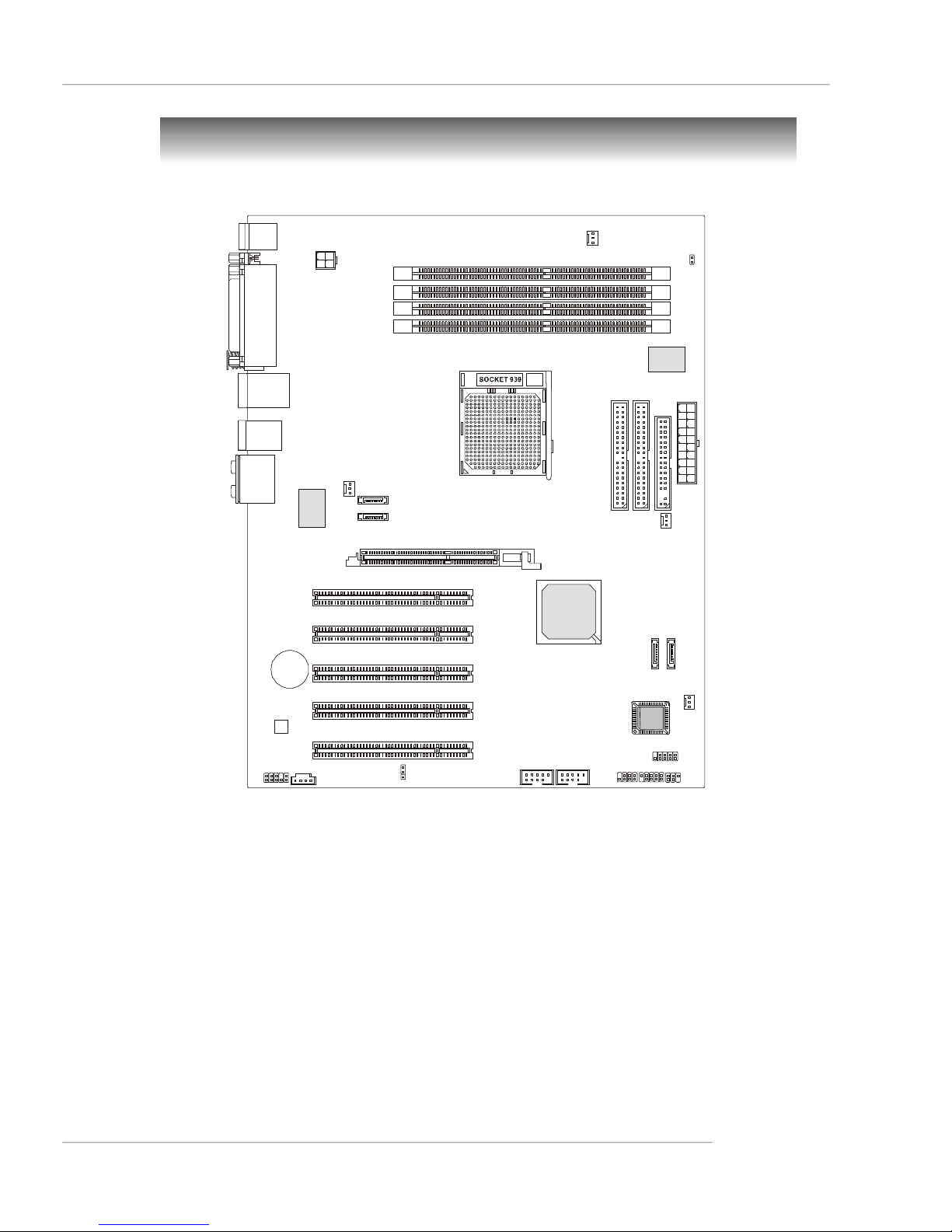
Mainboard Layout
1
W
P
J
DIMM4
DIMM3
DIMM2
DIMM1
J
C
R
1
1
1
1
E
8
8
1
I
C
J
PCI Slot2
PCI Slot3
- 250 Gb
1
A
T
A
S
+
1
N
A
F
S
S
O
I
B
1
D
U
A
J
Codec
1
D
C
J
K8N Neo2-FX Series (MS-7025 v1.X) ATX Mainboard
E-1-7

Hardware Setup
Chapter 2. Hardware Setup
Hardware Setup
This chapter tells you how to install the CPU, memory modules,
and expansion cards, as well as how to setup the jumpers on the
mainboard. Also, it provides the instructions on connecting the peripheral devices, such as the mouse, keyboard, etc.
While doing the installation, be careful in holding the components and follow the installation procedures.
E-2-1
MS-7025 ATX Mainboard
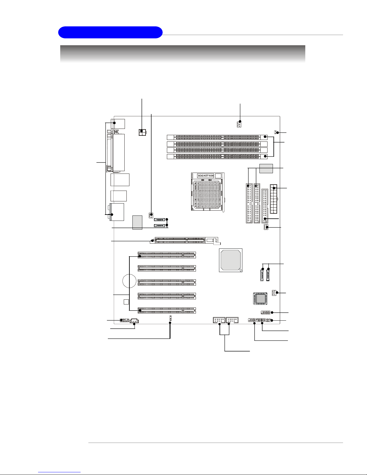
Quick Components Guide
Back Panel
I/O, p.2-12
SATA3, SATA4,
p.2-18
AGP Slot, p.2-25
JPW1, p.2-10
SFAN2, p.2-16
CPUFAN1, p.2-16
JCI1, p.2-17
DDR DIMMs,
p.2-7
IDE1/2, p.2-17
ATX1, p.2-10
FDD1, p.2-16
NB_FAN1,
p.2-16
SATA2, SATA1,
p.2-18
PCI Slots 1~5,
JAUD1, p.2-20
JCD1, p.2-18
JBAT1, p.2-24
E-2-2
p.2-25
S
O
I
B
JUSB1, JUSB2, p.2-19
SFAN1, p.2-16
JDB1, p.2-21
JIR1, p.2-20
JFP1, p.2-19
JFP2, p.2-19

Hardware Setup
Central Processing Unit: CPU
The mainboard supports AMD® Athlon64 processor. The mainboard uses a CPU socket
called Socket-939 for easy CPU installation. When you are installing the CPU, make
sure the CPU has a heat sink and a cooling fan attached on the top to
prevent overheating. If you do not have the heat sink and cooling fan, contact your
dealer to purchase and install them before turning on the computer.
For the latest information about CPU, please visit http://www.msi.com.tw/program/
products/mainboard/mbd/pro_mbd_cpu_support.php.
MSI Reminds You...
Overheating
Overheating will seriously damage the CPU and system, always make
sure the cooling fan can work properly to protect the CPU from
overheating.
Replacing the CPU
While replacing the CPU, always turn off the ATX power supply or
unplug the power supply’s power cord from grounded outlet first to
ensure the safety of CPU.
Overclocking
This motherboard is designed to support overclocking. However, please
make sure your components are able to tolerate such abnormal setting,
while doing overclocking. Any attempt to operate beyond product specifications is not recommended. We do not guarantee the damages
or risks caused by inadequate operation or beyond product
specifications.
E-2-3
MS-7025 ATX Mainboard
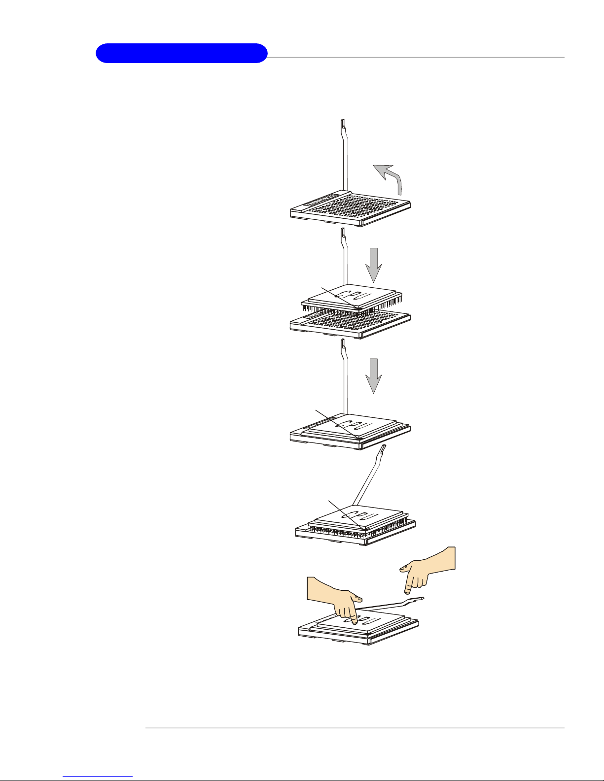
Gold arrow
Gold arrow
Gold arrow
Correct CPU placement
Incorrect CPU placement
Close
Press down
CPU Installation Procedures for Socket 939
1. Please turn off the power and
unplug the power cord before
installing the CPU.
2. Pull the lever sideways away
from the socket. Make sure to
raise the lever up to a 90-degree angle.
3.Look for the gold arrow. The gold
arrow should point as shown in
the picture. The CPU can only fit
in the correct orientation.
4.If the CPU is correctly installed,
the pins should be completely
embedded into the socket and
can not be seen. Please note
that any violation of the correct
installation procedures may
cause permanent damages to
your mainboard.
Sliding
Plate
Gold arrow
Open Lever
90 degree
O
X
5. Press the CPU down firmly into
the socket and close the lever.
As the CPU is likely to move while
the lever is being closed, always close the lever with your
fingers pressing tightly on top of
the CPU to make sure the CPU is
properly and completely embedded into the socket.
E-2-4
the CPU
Lever
Hardware Setup
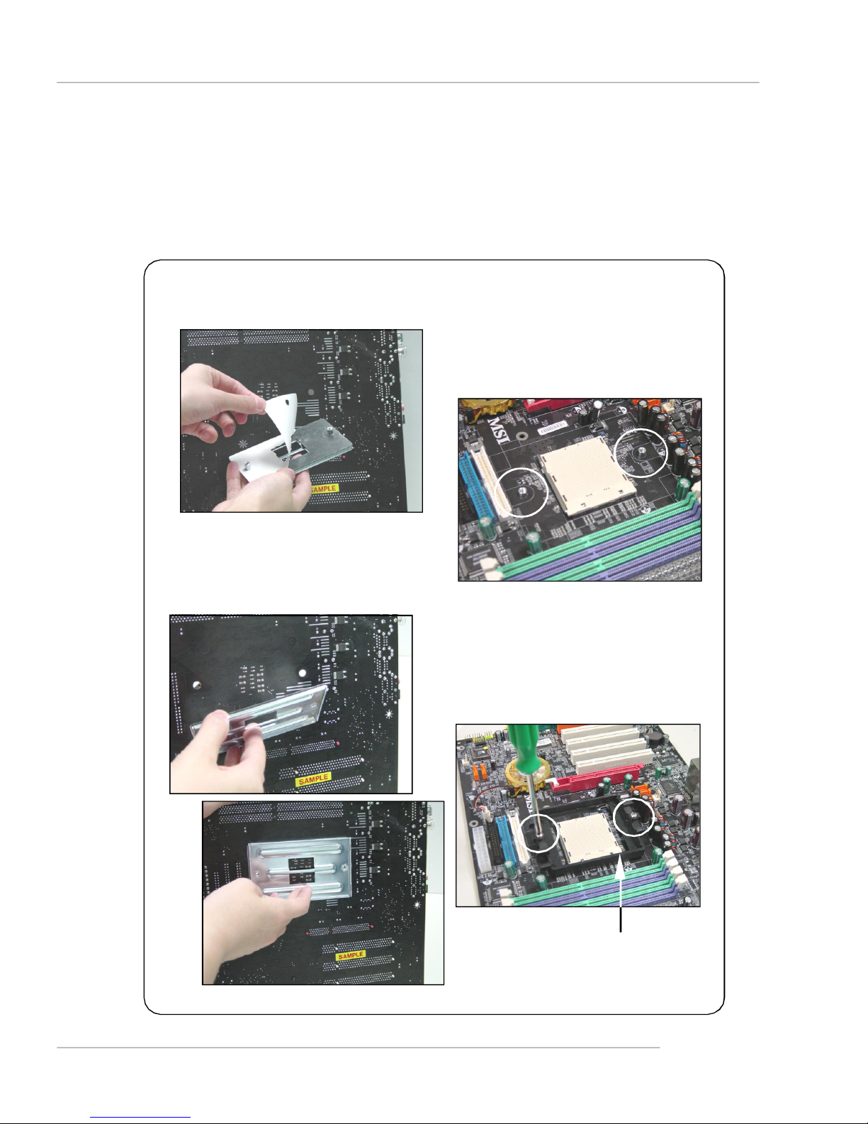
Installing AMD Athlon64 CPU Cooler Set
When you are installing the CPU, make sure the CPU has a heat sink and a
cooling fan attached on the top to prevent overheating. If you do not have the
heat sink and cooling fan, contact your dealer to purchase and install them before
turning on the computer.
1.Detach the shield of the backplate’s
paster.
2.Turn over the mainboard, and install
the backplate to the proper position.
3.Turn over the mainboard again, and
place the mainboard on the flat
surface.
Locate the two screw holes of the
mainboard.
4.Align the retention mechanism and
the backplate.
Fix the retention mechanism and the
backplate with two screws.
retention mechanism
E-2-5
MS-7025 ATX Mainboard
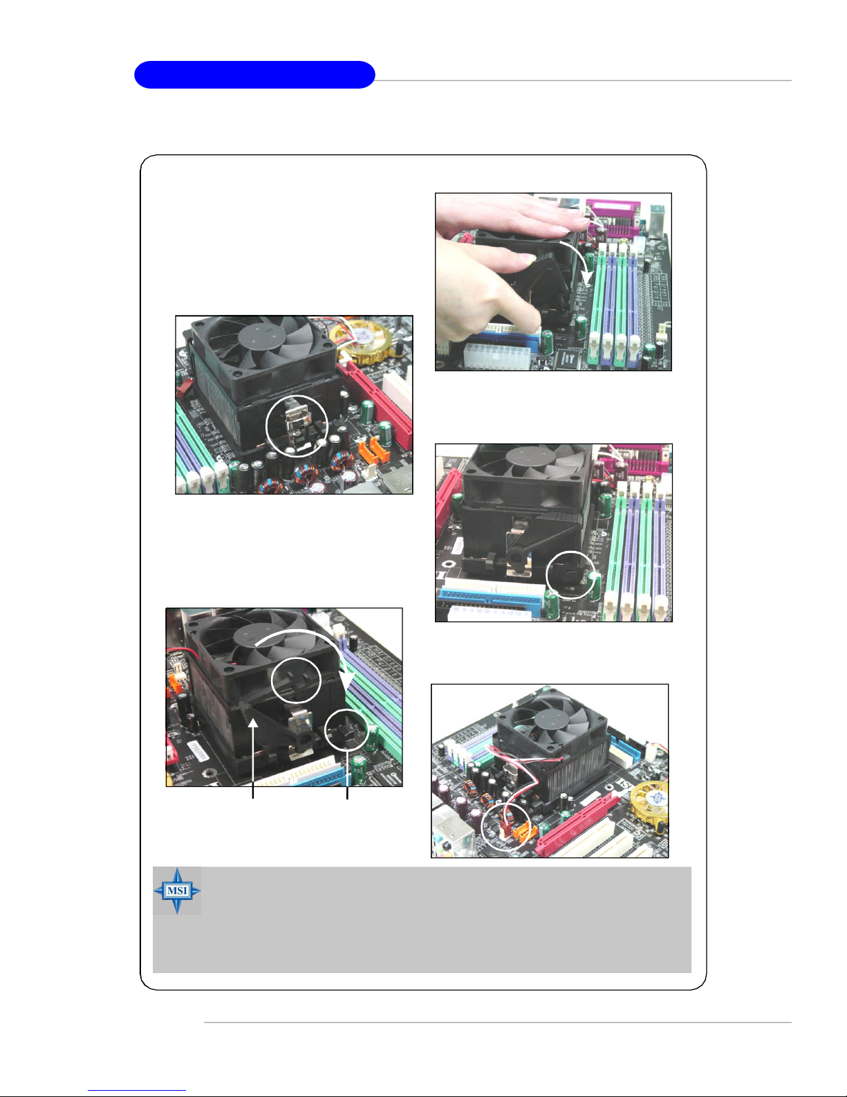
5.Position the cooling set onto the retention mechanism.
Hook one end of the clip to hook first,
and then press down the other end
of the clip to fasten the cooling set on
the top of the retention mechanism.
6.Locate the Fix Lever, Saftey Hook
and the Fixed Bolt.
7.Fastened down the lever.
8.Make sure the safety hook completely
clasps the fixed bolt of the retention
mechanism.
Lift up the intensive fixed lever.
9.Attach the CPU Fan cable to the CPU
fan connector on the mainboard.
Safety Hook
Fixed Lever
Fixed Bolt
MSI Reminds You...
While disconnecting the Safety Hook from the fixed bolt, it is necessary to keep an eye on your fingers, because once the Safety Hook is
disconnected from the fixed bolt, the fixed lever will spring back instantly.
E-2-6
Hardware Setup
Memory
The mainboard provides 4 slots for 184-pin DDR SDRAM DIMM (Double In-Line Memory
Module) modules and supports the memory size up to 4GB. You can install DDR266/
333/400/433/466/500/533 modules on the DDR DIMM slots (DDR 1~4).
For the updated supporting memory modules, please visit http://www.msi.com.tw/
program/products/mainboard/mbd/pro_mbd_trp_list.php.
DIMM1~4
(from bottom to top)
Introduction to DDR SDRAM
DDR (Double Data Rate) SDRAM is similar to conventional SDRAM, but doubles the
rate by transferring data twice per cycle. It uses 2.5 volts as opposed to 3.3 volts
used in SDR SDRAM, and requires 184-pin DIMM modules rather than 168-pin DIMM
modules used by SDR SDRAM. High memory bandwidth makes DDR an ideal solution
for high performance PC, workstations and servers.
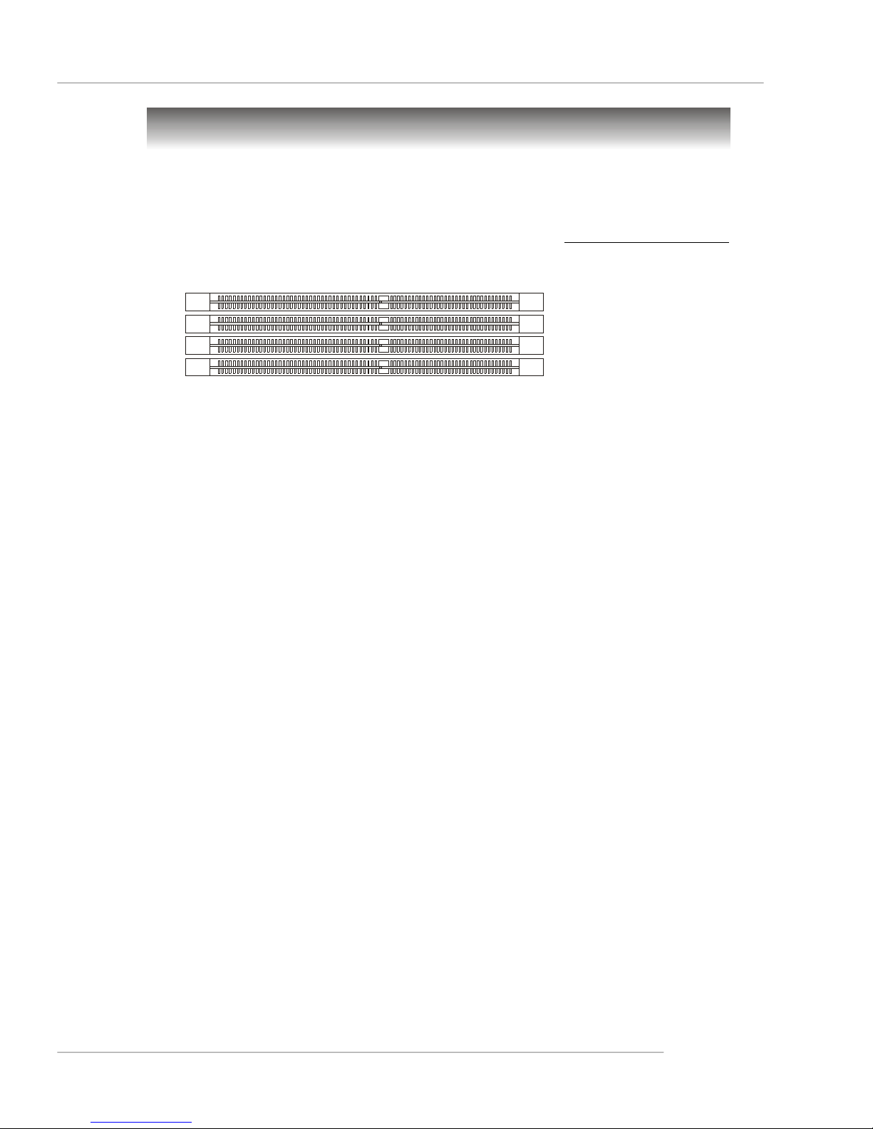
DIMM Module Combination
Install at least one DIMM module on the slots. Each DIMM slot supports up to a maximum
size of 1GB. Users can install either single- or double-sided modules to meet their
own needs. Please note that each DIMM can work respectively for single-
channel DDR, but there are some rules while using dual-channel DDR (Please
refer to the suggested DDR population table below). Users may install memory modules
of different type and density on different-channel DDR DIMMs. However, the same
type and density memory modules are necessary while using dual-channel DDR,
or instability may happen. Please refer to the following table for detailed dual-channel
DDR. Other combination not listed below will function as single-channel DDR.
E-2-7
MS-7025 ATX Mainboard
GREEN
DIMM1 (Ch A) DIMM2 (Ch B) DIMM3 (Ch A) DIMM4 (Ch B) System Density
128MB~1GB 128MB~1GB 256MB~2GB
128MB~1GB 128MB~1GB 128MB~1GB 128MB~1GB 512MB~4GB
MSI Reminds You...
-Dual-channel DDR works ONLY in the 3 combinations listed in
the table shown in the previous page.
-Please select the identical memory modules to install on the dual
channel, and DO NOT install three memory modules on three
DIMMs, or it may cause some unkonwn failure.
-Always insert the memory modules into the GREEN slots first, and
it is strongly recommended not to insert the memory modules into
the PURPLE slots while the GREEN slots are left empty.
-This mainboard DO NOT support the memory module installed
with more than 18 pieces of IC (integrated circuit).
PURPLE
GREEN
128MB~1GB 128MB~1GB 256MB~2GB
PURPLE
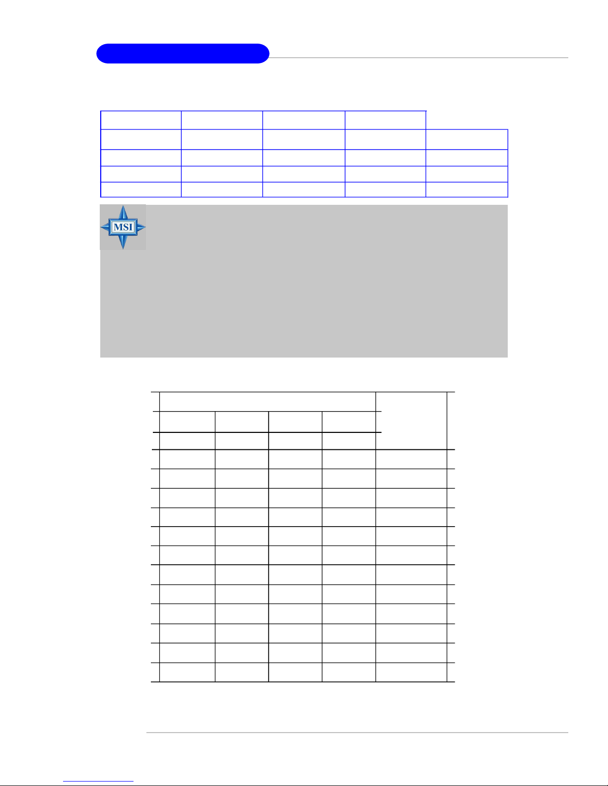
Recommended Memory Combination List
DIMM Slots
Green
DIMM1
S
D
S -
D -
S
Purple
DIMM2 DIMM3DIMM4
- -
-
-
-
S
Green
S
-
D-
S -
D -
-
- - S S
D D
- S
D
S: Single Side D: Double Side
S
D
- D D
S
D
Purple
-
-
-
-
-
S
D
Max Speed
DDR 400
DDR 400
DDR 400
DDR 400
DDR 400
DDR 333
DDR 400
DDR 400
DDR 400
DDR 400
DDR 400
DDR 333
E-2-8
Hardware Setup
MSI Reminds You...
1. The maximum memory speed decreases when the following two
Memory Combination is selected (you can also refer to the Recommended Memory Combination list shown in the previous page:
-Each channel is installed with two double-sided memory mod-
ules
-Both DIMM1 and DIMM3 slots are installed with double-sided
memory module.
2. Due to the South Bridge resource deployment, the system density will only be detected up to 3+GB (not full 4GB) when each
DIMM is installed with an 1GB memory module.
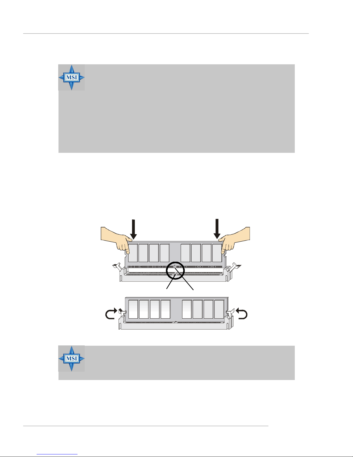
Installing DDR Modules
1. The DDR DIMM has only one notch on the center of module. The module will only
fit in the right orientation.
2. Insert the DIMM memory module vertically into the DIMM slot. Then push it in until
the golden finger on the memory module is deeply inserted in the socket.
3. The plastic clip at each side of the DIMM slot will automatically close.
MSI Reminds You...
You can barely see the golden finger if the module is properly inserted in the socket.
Volt
Notch
E-2-9
MS-7025 ATX Mainboard
Power Supply
The mainboard supports ATX power supply for the power system. Before inserting
the power supply connector, always make sure that all components are installed
properly to ensure that no damage will be caused.
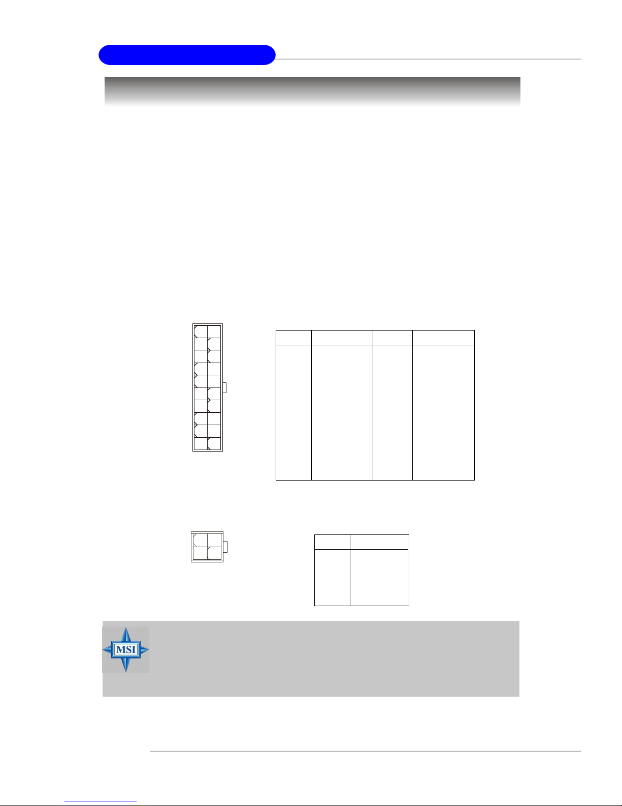
ATX 20-Pin Power Connector: ATX1
This connector allows you to connect to an ATX power supply. To connect to the ATX
power supply, make sure the plug of the power supply is inserted in the proper
orientation and the pins are aligned. Then push down the power supply firmly into the
connector.
ATX 12V Power Connector: JPW1
This 12V power connector is used to provide power to the CPU.
ATX1 Pin Definition
10
1
ATX1
20
11
PIN SIGNAL
1 3.3V
2 3.3V
3 GND
4 5V
5 GND
6 5V
7 GND
8 PW_OK
9 5V_SB
10 12V
PIN SIGNAL
11 3.3V
12 -12V
13 GND
14 PS_ON
15 GND
16 GND
17 GND
18 -5V
19 5V
20 5V
1 3
JPW1
MSI Reminds You...
1. These two connectors connect to the ATX power supply and have to
work together to ensure stable operation of the mainboard.
2. Power supply of 300 (and up) watt is highly recommended for system
stability.
E-2-10
JPW1 Pin Definition
PIN SIGNAL
42
1 GND
2 GND
3 12V
4 12V
Hardware Setup
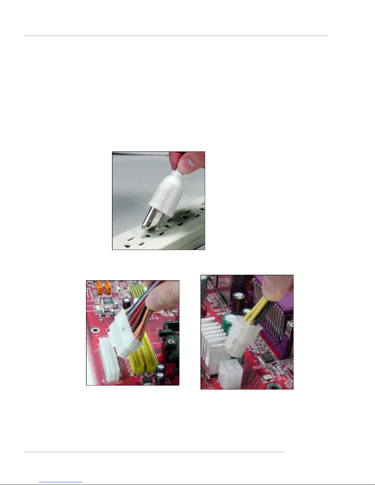
Important Notification about Power Issue
NForce chipset is very sensitive to ESD (Electrostatic Discharge), therefore this
issue mostly happens while the users intensively swap memory modules under S5
(power-off) states, and the power code is plugged while installing modules. Due to
several pins are very sensitive to ESD, so this kind of memory-replacement actions
might cause chipset system unable to boot. Please follow the following solution to
avoid this situation.
Unplug the AC power cable (shown in figure 1) or unplug the ATX1 & JPW1 power
connectors (shown in figure 2 & figure 3) before the 1st installation or during system upgrade procedure.
Figure 1:
Unplug the AC power cable
Figure 2:
Unplug the ATX1 power connector
Figure 3:
Unplug the JPW1 power connector
E-2-11
MS-7025 ATX Mainboard
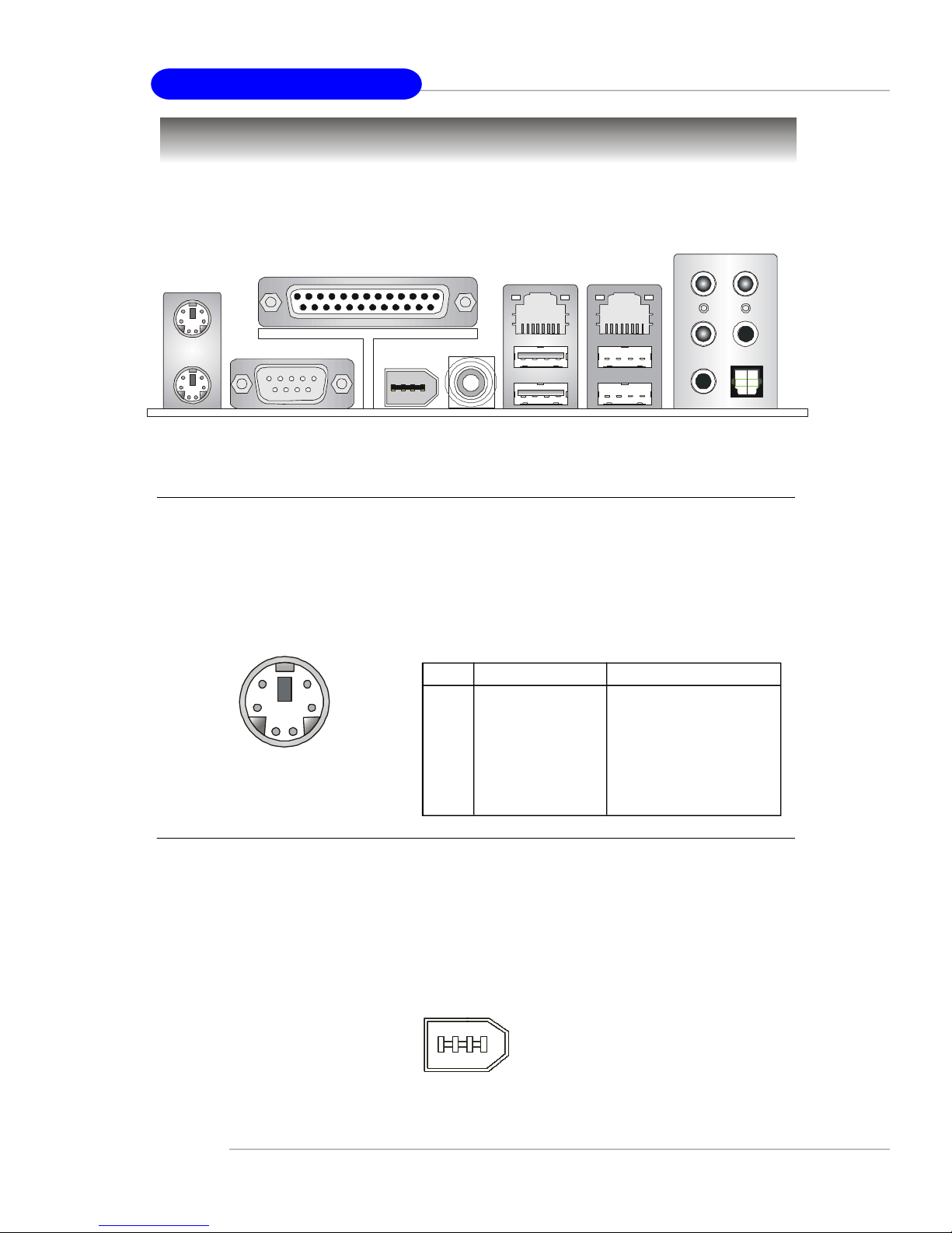
Back Panel
The back panel provides the following connectors:
L-In
RS-Out
Parallel
Mouse
Keyboard
COM 1
1394 Port
(Optional)
SPDIF
Out
(Coaxial)
LAN
USB Ports
LAN
L-Out
Mic
CS-Out
SPDIF Out
(Optical)
Mouse Connector (Green) / Keyboard Connector (Purple)
The mainboard provides a standard PS/2® mouse/keyboard mini DIN connector for
attaching a PS/2® mouse/keyboard. You can plug a PS/2® mouse/keyboard directly
into this connector. The connector location and pin assignments are as follows:
Pin Definition
6
4
2
PS/2 Mouse / Keyboard
(6-pin Female)
5
3
1
PIN SIGNAL DESCRIPTION
1 Mouse/Keyboard Data Mouse/Keyboard data
2 NC No connection
3 GND Ground
4 VCC +5V
5 Mouse/Keyboard Clock Mouse/Keyboard clock
6 NC No connection
IEEE1394 Port (Optional)
The back panel provides one standard IEEE 1394 port. The standard IEEE1394 port
connects to IEEE1394 devices without external power. The IEEE1394 high-speed
serial bus complements USB by providing enhanced PC connectivity for a wide range
of devices, including consumer electronics audio/video (A/V) appliances, storage
peripherals, other PCs, and portable devices.
E-2-12
IEEE1394 Port
Hardware Setup
Serial Port Connector
The mainboard offers one 9-pin male DIN connector as the serial port. The port is a
16550A high speed communication port that sends/receives 16 bytes FIFOs. You
can attach a serial mouse or other serial devices directly to the connector.
Pin Definition
1 2 3 4 5
6 7 8 9
9-Pin Male DIN Connector
PIN SIGNAL DESCRIPTION
1 DCD Data Carry Detect
2 SIN Serial In or Receive Data
3 SOUT Serial Out or Transmit Data
4 DTR Data Terminal Ready)
5 GND Ground
6 DSR Data Set Ready
7 RTS Request To Send
8 CTS Clear To Send
9 RI Ring Indicate
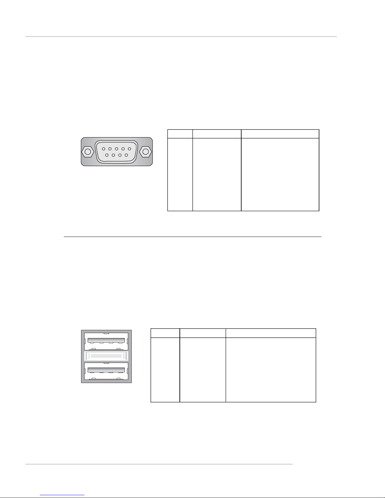
USB Connectors
The mainboard provides two OHCI (Open Host Controller Interface) Universal Serial
Bus roots for attaching USB devices such as keyboard, mouse or other USB-compatible devices. You can plug the USB device directly into the connector.
USB Port Description
PIN SIGNAL DESCRIPTION
1 VCC +5V
1 2 3 4
5 6 7 8
USB Ports
2 -Data 0 Negative Data Channel 0
3 +Data0 Positive Data Channel 0
4 GND Ground
5 VCC +5V
6 -Data 1 Negative Data Channel 1
7 +Data 1 Positive Data Channel 1
8 GND Ground
E-2-13
MS-7025 ATX Mainboard
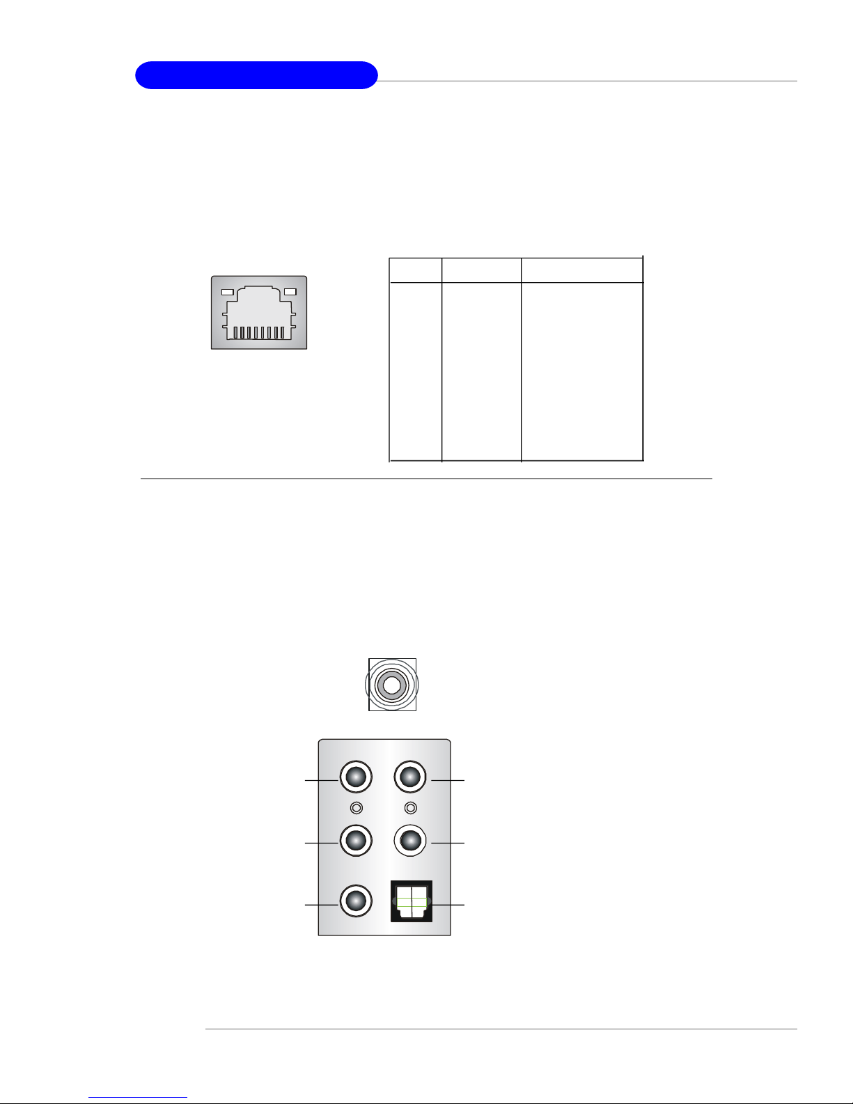
LAN (RJ-45) Jack
The mainboard provides 2 standard RJ-45 jacks for connection to single Local Area
Network (LAN). This Giga-bit LAN enables data to be transferred at 1000, 100 or
10Mbps. You can connect a network cable to either LAN jack.
Giga-bit LAN Pin Definition
PIN SIGNAL DESCRIPTION
1 D0P Differential Pair 0+
2 D0N Differential Pair 03 D1P Differential Pair 1+
RJ-45 LAN Jack
4 D2P Differential Pair 2+
5 D2N Differential Pair 26 D1N Differential Pair 17 D3P Differential Pair 3+
8 D3N Differential Pair 3-
Audio Port Connectors
The left 3 audio jacks are for 2-channel mode for stereo speaker output: Line Out is
a connector for Speakers or Headphones. Line In is used for external CD player,
Tape player, or other audio devices. Mic is a connector for microphones.
However, there is an advanced audio application provided by Realtek ALC850 to
offer support for 7.1-channel audio operation and can turn rear audio connectors
from 2-channel to 4-/5.1-/7.1 channel audio.
S/PDIF Out-Coaxial
Line In or
Side Speaker Out
(in 7.1CH)
Line Out
MIC
Rear Speaker Out
(in 7.1CH / 6CH/ 4CH)
Center/Subwoofer
Speaker Out
( in 7.1CH / 6CH)
S/PDIF Out-Optical
(in 7.1CH / 6CH)
E-2-14
Hardware Setup
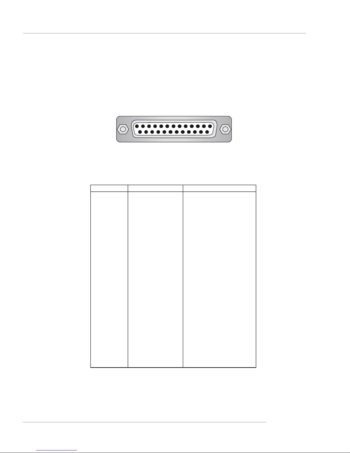
Parallel Port Connector: LPT1
The mainboard provides a 25-pin female centronic connector as LPT. A parallel port
is a standard printer port that supports Enhanced Parallel Port (EPP) and Extended
Capabilities Parallel Port (ECP) mode.
13 1
25
14
Pin Definition
PIN SIGNAL DESCRIPTION
1 STROBE Strobe
2 DATA0 Data0
3 DATA1 Data1
4 DATA2 Data2
5 DATA3 Data3
6 DATA4 Data4
7 DATA5 Data5
8 DATA6 Data6
9 DATA7 Data7
10 ACK# Acknowledge
11 BUSY Busy
12 PE Paper End
13 SELECT Select
14 AUTO FEED# Automatic Feed
15 ERR# Error
16 INIT# Initialize Printer
17 SLIN# Select In
18 GND Ground
19 GND Ground
20 GND Ground
21 GND Ground
22 GND Ground
23 GND Ground
24 GND Ground
25 GND Ground
E-2-15
MS-7025 ATX Mainboard
Connectors
The mainboard provides connectors to connect to FDD, IDE HDD, case, LAN, USB
Ports, IR module and CPU/System FAN.
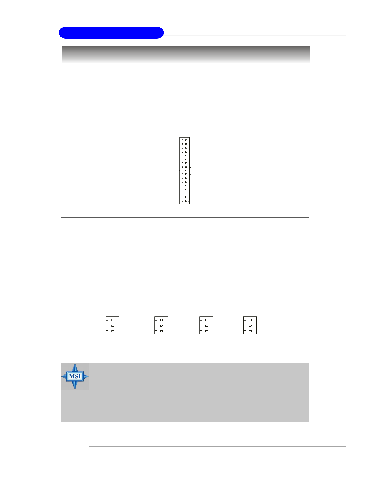
Floppy Disk Drive Connector: FDD1
The mainboard provides a standard floppy disk drive connector that supports 360K,
720K, 1.2M, 1.44M and 2.88M floppy disk types.
FDD1
Fan Power Connectors: CPUFAN1 / SFAN1 / SFAN2 / NBFAN1
The CPUFAN1 (processor fan), SFAN1 (system fan 1), SFAN2 (system fan 2) and
NBFAN1 (NorthBridge Chipset fan) support system cooling fan with +12V. It supports
three-pin head connector. When connecting the wire to the connectors, always take
note that the red wire is the positive and should be connected to the +12V, the black
wire is Ground and should be connected to GND. If the mainboard has a System
Hardware Monitor chipset on-board, you must use a specially designed fan with
speed sensor to take advantage of the CPU fan control.
GND
+12V
SENSOR
CPUFAN1
MSI Reminds You...
1.Always consult the vendors for proper CPU cooling fan.
2.CPUFAN1 supports fan control. You can install Core Center utility that will automatically control the CPU fan speed according to
the actual CPU temperature.
3. Please refer to the recommended CPU fans at AMD® official
website.
SFAN1
GND
+12V
NC
GND
+12V
NC
SFAN2
GND
+12V
Sensor
NBFAN1
E-2-16
 Loading...