

MSI 651M-V, MS-7005 Instruction Manual

i
FCC-B Radio Frequency Interference Statement
This equipment has been tested and found to comply with the lim its for a class B digital devic e, pur su ant to part 15 of
the FCC rules. These limits are designed to provide reasonable protection against harmful interference when the
equipment is operated in a commercial environment. This equipment generates, uses and can radiate radio frequency
energy and, if not installed and used in accordance with the instruction manual, may cause harmful interference to
radio communications. Operation of this equipment in a residential area is likely to cause harmful interference, in
which case the user will be required to correct the interference at his own expense.
Notice 1
The changes or modifications not expressly approved by the party responsible for compliance could void the user’s
authority to operate the equipment.
Notice 2
Shielded interface cables and A.C. power cord, if any, must be used in order to comply with the emission limits.
VOIR LA NOTICE D’NSTALLATION AVANT DE RACCORDER AU RESEAU.
Micro-Star International
MS-7005
This device complies with Part 15 of the FCC Rules. Operation is subject to the following two conditions:
(1) this device may not cause harmful interference, and
(2) this device must accept any interference received, including interference that may cause undesired operation
G52-M7005XD

ii
Copyright Notice
The material in this document is the intellectual property of MICRO-STAR INTERNATIONAL. We take every care in
the preparation of this document, but no guarantee is given as to the correctness of its contents. Our products are
under continual improvement and we reserve the right to make changes without notice.
Trademarks
All trademarks are the properties of their respective owners.
AMD, Athlon™ Athlon™XP, Thoroughbred™ and Duron™ are registered trademarks of AMD Corporation.
Intel® and Pentium® ar e registered trademarks of Intel Cor po ration.
PS/2 and OS® 2 are registered trademarks of International Business Machines Corporation.
Microsoft® is a registered trademark of Microsoft Corporation. Windows® 98/2000/NT/XP are registered trademarks
of Microsoft Corporatio n.
NVIDIA, the NVIDIA logo, DualNet, and nForce are registered trademarks or trademarks of NVIDIA Corporation in the
United States and/or other countries.
Netware® is a registered trademark of Novell, Inc.
Award® is a registered trademark of Phoenix Technologies Ltd.
AMI® is a registered trademark of American Megatrends Inc.
Kensington and MicroSaver are registered trademarks of the Kensington Technology Group.
PCMCIA and CardBus are registered trademarks of the Personal Computer Memory Card International Association.
Revision History
Revision Revision History Date
V2.0 First release of for PCB 2.x with chipsets SiS651 & SiS962L April 2004
V2.1 First release of Multi-language version for PCB 2.x April 2004
V2.2 USB connector pin definition updated October 2004

iii
Safety Instructions
1. Always read the safety instructions carefully.
2. Keep this Use r Man ual for future reference.
3. Keep this eq uipm e nt a way fr om humidity.
4. Lay this equipment on a reliable flat surface before setting it up.
5. The openings on the enclosure are for air convection hence protects the equipment from overheating. Do not
cover the openings.
6. Make sure the voltage of the power source and adjust properly 110/220V before connecting the equipment to the
power inlet.
7. Place the power cord such a way that people can not step on it. Do not place anything over the power cord.
8. Always Unplug the Power Cord before inserting any add-on card or module.
9. All cautions and warnings on the equipment should be noted.
10. Never pour any liquid into the opening that could damage or cause electrical shock.
11. If any of the following situations arises, get the equipment checked by a service personnel:
- The power cord or plug is damaged .
- Liquid has penetrated into the equipment.
- The equipment has been expose d to m oistur e.
- The equipment does not work well or you can not get it work according to User Manual.
- The equipment has dropped and damaged.
- The equipment has obvious sign of breakage.
12. Do not leave this equipment in an environment unconditioned, storage temperature above 600 C (1400F), it may
damage the equipment.
CAUTION: Danger of explosion if battery is incorrectly replaced. Replace only with
the same or equivalent type recommended by the manufacturer.

iv
Table of Content
English.....................................................................1
Deutsch.................................................................... 15
Français...................................................................25
简体中文...................................................................37
繁體中文...................................................................49
Nederlands..............................................................60
日本語.......................................................................73
1
Introduction
Thank you for choosing the 651M-V Series (MS-7005 v2.X) micro ATX mainboard. The 651M-V Series
is based on SiS ® 651 & 962L chipsets for optimal system efficiency. Designed to fit the advanced Intel
® Pentium ® 4 processors in 478 pin package, the 651M-V Series delivers a high performance and
professional desktop platform solution.
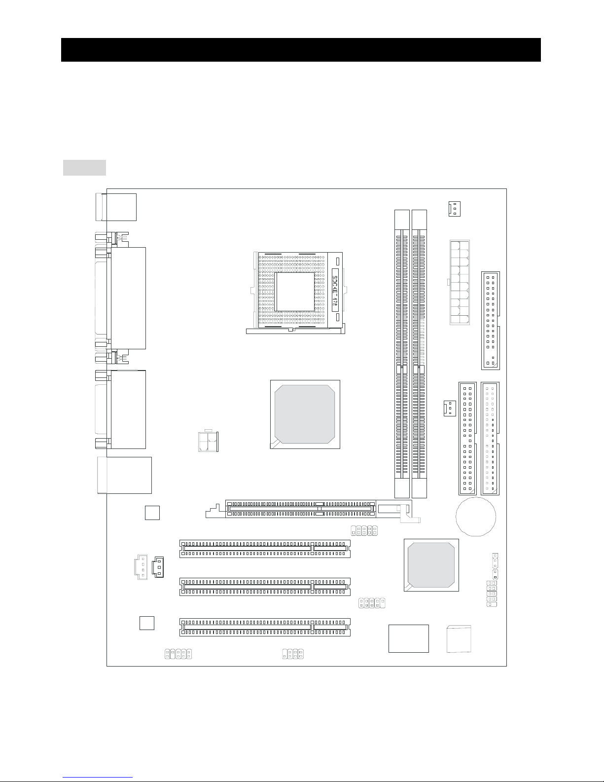
Layout
BATT
+
Si S
962L
SiS 651
D
D
R
1
D
D
R
2
JA UD1
A
T
X
P
o
w
e
r
S
u
p
p
l
y
S
Y
S
F
A
N
1
CP UF AN1
JFP 1
JFP2
Codec
Real tek
8201B L
Winbond
W83697HF
BIOS
PCI Slot 3
PCI Slot 2
PCI Slot 1
I
D
E
2
F
D
D
1
I
D
E
1
ATX 12V
Top : m ouse
Bottom: keyboard
T: LAN jack
B: USB ports
JCD1
AGP Slot
JC I1
JUSB1
JUSB2
JB AT1
JSP1
Top : Parallel Port
Bottom:
COM A
VGA Port
Top :
Game port
Bottom:
Mic
Line-Out
Line-In

2
Specifications
CPU
z Socket 478 for P4 processors (Northwood/Pres cott) at 400 MHz/533 MHz
z Supports up to 3.06GHz and higher speed CPU
z Hyper-Threading CPU
(For the latest information about CPU, please visit
http://www.msi.com.tw/program/products/mainboard/mbd/pro_mbd_cpu_support.php)
Chipset
z SiS 651 (702 pin BGA)
- High performance host interface 400 MHz/533 MHz
- Supports 64 Bit high performance DDR200/266/333 memory controller
- Supports AGP 4X/2X interface with fast write transaction
- High throughput SiS MuTIOL connect to SiS962L MuTIOL Media I/O
- High performance 2D/3D and Video Accelerator
z SiS 962L MuTIOL Media I/O (371BGA)
- High performance MuTIOL connect to SiS series NB
- Integrated multi-threaded I/O link ensures c oncurrency of up/down stream data transfer with
1.2GB/s bandwidth
- Integrated USB 2.0/1.1 host controller and Fast Ethernet MAC controller
- Integrated audio controller with AC97 interface
- Advanced power management and PC2001 compliance
- Integrated RTC, DMA, interrupt, and keyboard controllers
- Integrated PCI to LPCC bridge
Main Memo ry
z Supports two memory banks using two 184-pin unbuffered DDR 200/266/333 DIMMs
z Supports up to 2GB memory size without ECC
(For the updated supporting memory modules, please visit
http://www.msi.com.tw/program/products/mainboard/mbd/pro_mbd_trp_list.php)
Slots
z One AGP (Accelerated Graphics Port) slot that supports AGP 2.0 4X/2X
z Three PCI 2.2 32-bit Master PCI Bus slots (support 3.3V/5V PCI bus interface)

3
On-Board IDE
z Dual IDE controllers integrated in SiS 962L
z Support Bus Master, Ultra DMA 33/66/100/133 operation modes
z Can connect up to four IDE devices
On-Board Peripherals
z On-Board Peripherals includes:
- 1 floppy port supports 2 FDDs with 360K, 720K, 1.2M, 1.44M and 2.88Mbytes
- 1 serial port (COMA) and 1 VGA port
- 1 parallel port supports SPP/EPP/ECP mode
- 6 USB 2.0/1.1 ports (Rear * 2 / Front * 4)
- 1 Line-In/Line-Out/Mic-In port
- 1 game port
- 1 RJ-45 LAN connector
Audio
z AC97 link controller integrated in SiS 962L SB
z 6 channels S/W audio codec Realtek ALC655 codec
- Compliance with AC97 2.2 Spec
- Meets PC2001 audi o performance requi rement
LAN
z SiS 962L integrated MAC + Realtek 8201BL PHY
- Support 10Mb/s and 100Mb/s auto-negotiation operation
- Compliance with PCI 2.2 and PC99 standard
z Supports Wake-On-LAN and remote Wake-up
z Supports ACPI power management
BIOS
z 4MB Award BIOS with PNP BIOS, A CP I, SMBI OS 2.3, Green and Boot Block
z Provides DMI 2.0, WFM 2.0, WOL, WOR, chassis intrusi o n, and SMBus fo r syst em management
Dimension
z Micro-ATX Form Factor: 24.5 cm (L) x 20.0 cm (W)
Mounting
z 6 mounting holes
Others
z Live BIOS/Live Driver Update
z PC2001 Compliant
z Suspends to RAM/Disk
4
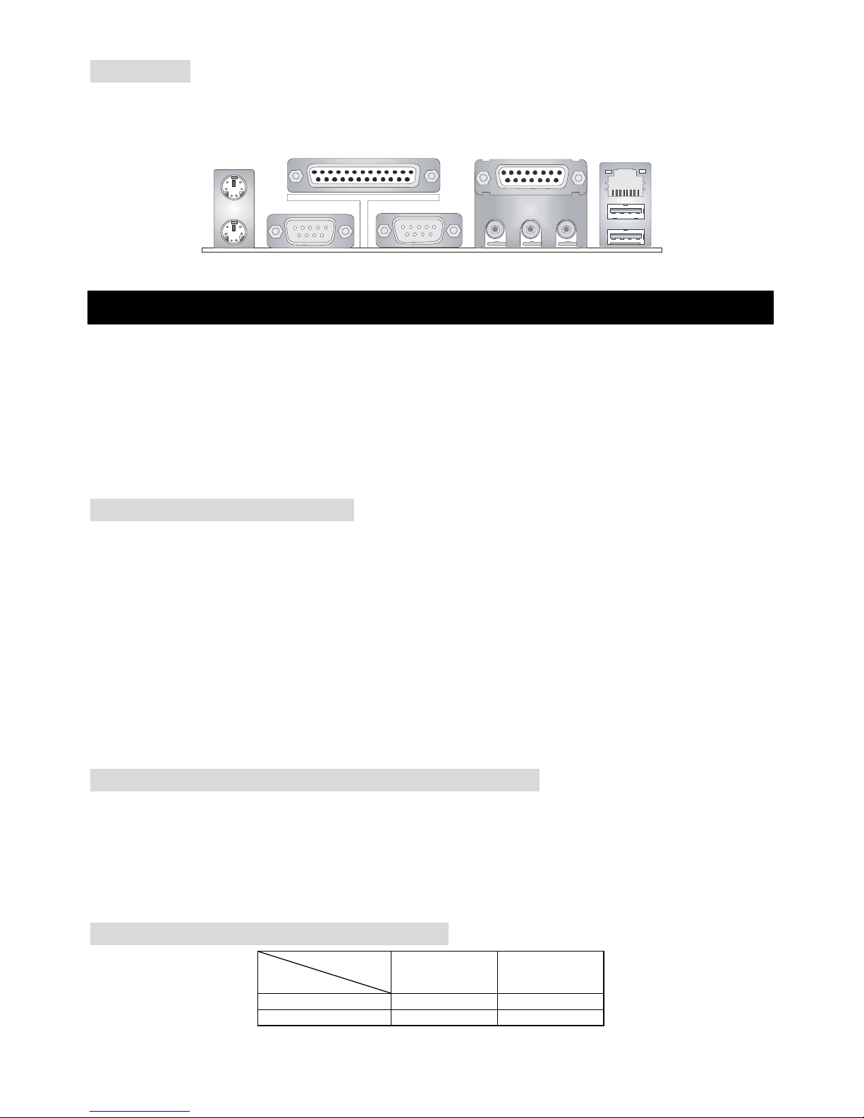
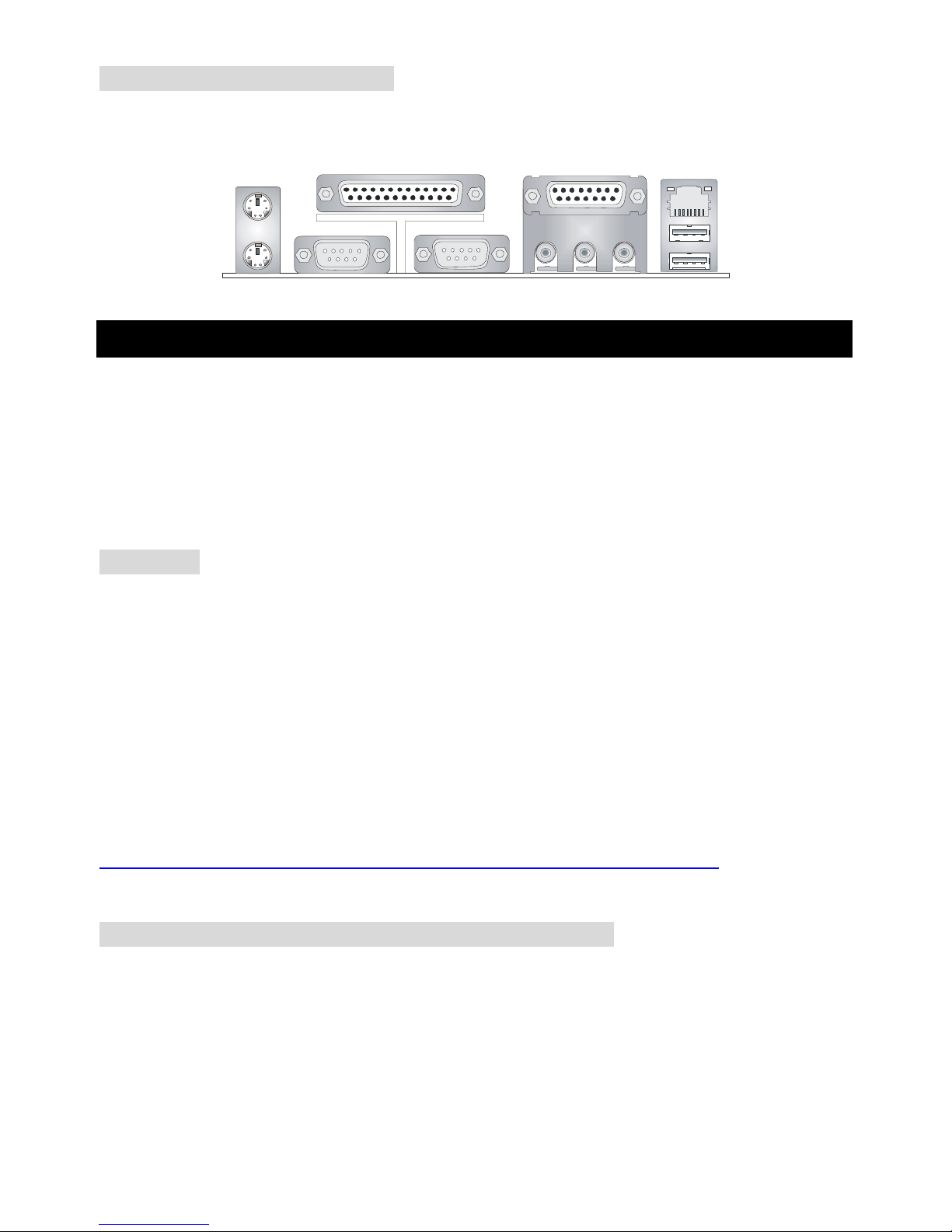
Back Panel
The back panel provides the following connectors:
Mou se
Keyboa rd
Para llelPara llel
COMA
VGA Port
L-out L-in MI C
Midi/Joystick
LANLAN
USB Ports
Hardware Setup
This chapter tells you how to install the CPU, memory modules, and exp ansion cards, as well as how to
setup the jumpers on the mainboard. It also provides the instructions on connecting the peripheral
devices, such as the mouse, keyboard, etc.
While doing the installation, be careful in holding the components and follow the installation
procedures.
Central Processing Unit: CPU
The mainboard supports Intel®Pentium®4 Willamette, Celeron, Northwood and Prescott processor in
the 478 pin package. The mainboard uses a CPU socket called PGA478 for easy CPU installation.
When you are installing the CPU, make sure the CPU has a heat sink and a cooling fan attached
on the top to prevent overheating. If you do not find the heat sink and cooling fan, contact your
dealer to purchase and install them before turning on the computer.
For the latest information about CPU, please visit
http://www.msi.com.tw/program/products/mainboard/mbd/pro_mbd_cpu_support.php
Example of CPU Core Speed Derivation Procedure
If CPU Clock = 133MHz
Core/Bus ratio = 23
then CPU core s
p
eed = Host Clock x Core/Bus ratio
= 133MHz x 23
= 3.06 GHz
Memory Speed/CPU FSB Support Matrix
Memory
FSB
DDR 266 DDR 333
400MHz OK OK
533MHz OK OK

5
CPU Installation Procedures for Socket 478
1. Please turn off the power and unplug the power cord before installing the CPU.
2. Pull the lever sideways away from the socket. Make sure to raise the lever up to a 90-degree
angle.
3. Look for the gold arrow. The gold arrow should point towards the lever pivot. The CPU can only
fit in the correct orientation.
4. If the CPU is correctly installed, the pins should be completely embedded into the socket and
can not be seen. P lease note that any violation of the correct installation procedures may
cause permanent damages to your mainboard.
5. Press the CPU down firmly into the socket and close the lever. As the CPU is lik ely t o move
while the lever is being closed, always close the lever with your fi ngers pressing tightly on top of
the CPU to make sure the CPU is properly and completely embedded into the socket.
Installing the CPU Fan
As processor technology pushes to faster speeds and higher perf orm ance, t herm al managem ent
becomes increasingly important. To dissipate heat, you need to attach the CPU cooling fan and
heatsink on top of the CPU. Follow the instructions below to install the Heatsink/Fan:
1. Locate the CPU and its retention mechanism on the motherboard.
2. Position the heatsink onto the retention mechanism.
3. Mount the fan on top of the heatsink. Press down the fan until its four clips get wedged in the
holes of the retention mechanism.
4. Press the two levers down to fasten the fan. Each lever can be pressed down in only ONE
direction.
5. Connect the fan power cable from the mounted fan to the 3-pin fan power connector on the
board.
Memory
The mainboard provides two 184-pin unbuffered DDR200/DDR266/DDR333 DDR SDRAM, and
supports the memory size up to 2GB. To operate properly, at least one DIMM module must be installed.
For the updated supporting memory modules, please visit
http://www.msi.com.tw/program/products/mainboard/mbd/pro_mbd_trp_list.php
6
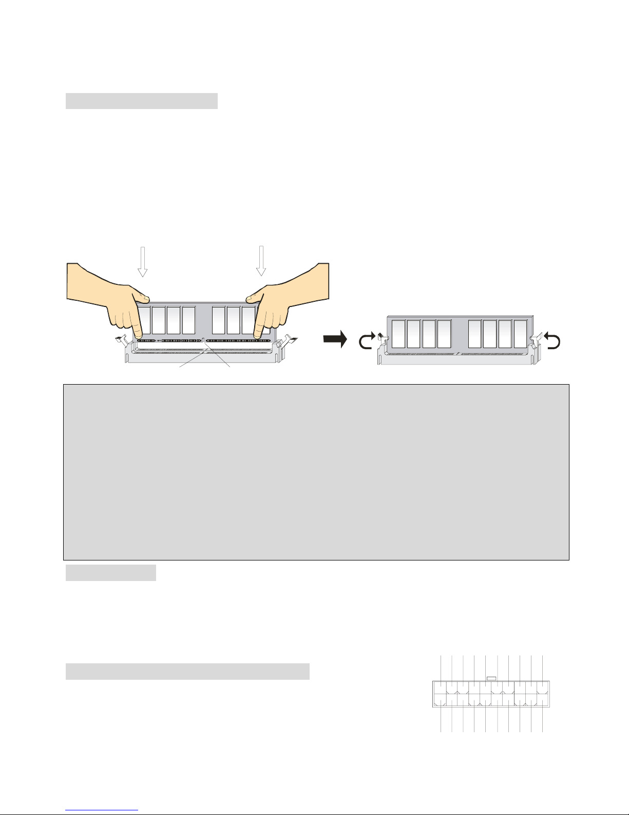
Install at least one DIMM module on the slots. Memory modules can be installed on the slots in any
order. You can install either single- or double-sided modules to meet your own needs.
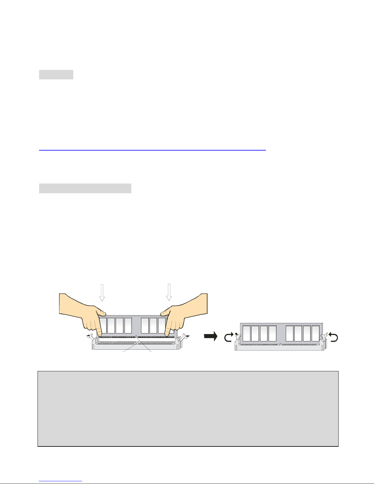
Installing DDR Modules
1. The DDR DIMM has only one notch on the center of module. The module will only fit in the right
orientation.
2. Insert the DIMM memory module vertically into the DIMM slot. Then push it in until the golden
finger on the memory module is deeply inserted in the socket.
3. The plastic clip at ea ch sid e o f the D IMM slot will automat ically close.
NotchVolt
MSI Reminds You. ..
Overheating…
Overheating will seriously damage the CPU and system, always make sure the cooling fan can work
properly to protect the CPU from overheating.
Replacing the CPU…
While replacing the CPU, always turn off the ATX pow er supply or unplug the power supply’s power
cord from grounded outlet first to ensure the safety of CPU.
Power Supply
The mainboard supports ATX power supply for the power system. Before ins erting the power supply
connector, always make sure that all components are installed properly to ensure that no damage will
be caused.
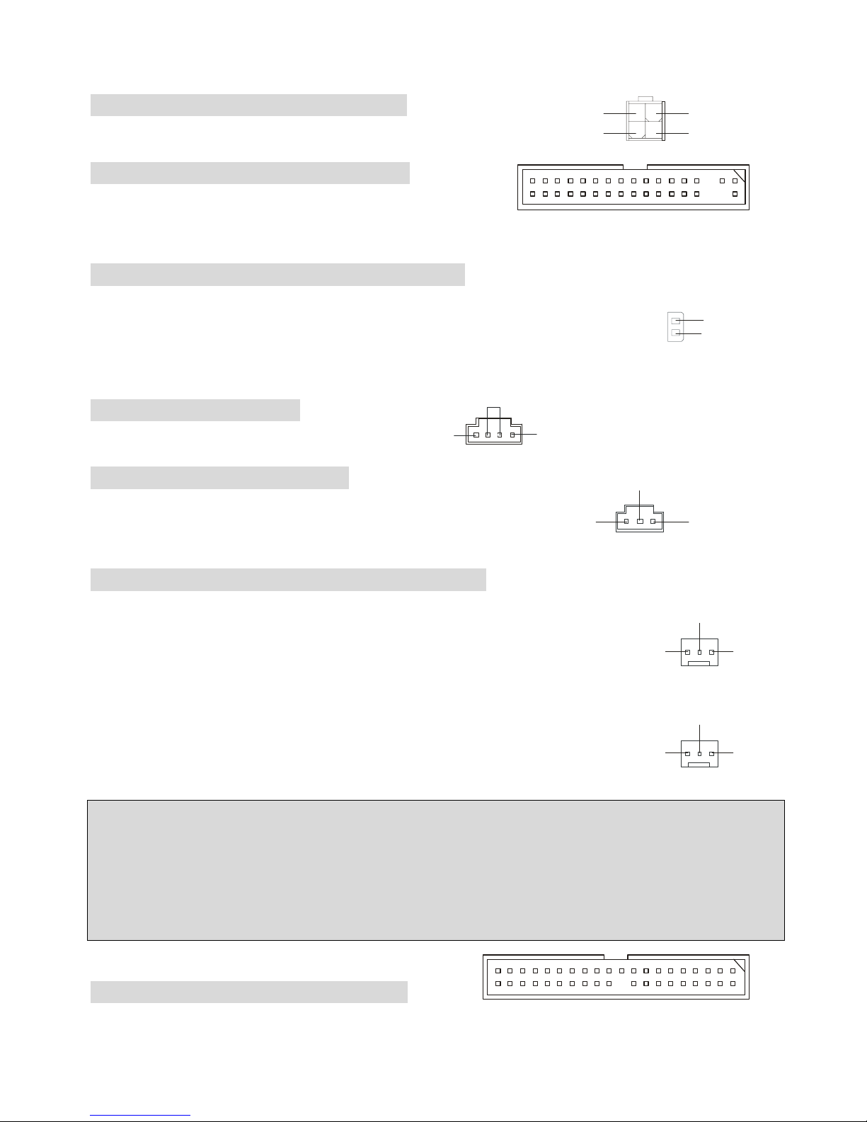
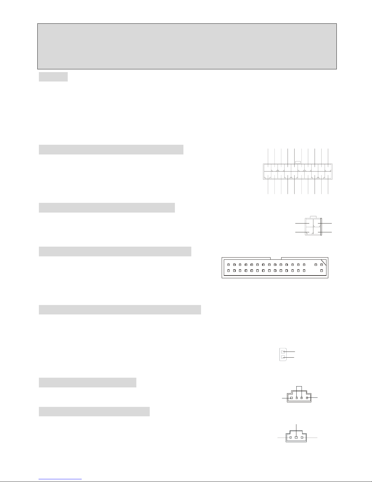
ATX 20-Pin Power Connector: CONN1
This connector allows you to connect to an ATX power supply. To
connect to the ATX power supply, make sure the plug of the power supply
is inserted in the proper orientation and the pins are aligned. Then push
1
11
3.3V
3.3V
3.3V
-12V
GND
GND
GND
GND
GND
GND
GND
PW_OK
-5V
5V_SB
5V
5V
12 V
5V
PS_O N
5V
10
20
7
down the power supply firmly into the connector.
ATX 12V Power Connector: ATX12V
This 12V power connector is used to provide power to the CPU.
Floppy Disk Drive Connector: FDD1
The mainboard provides a standard floppy disk drive
connector that supports 360K, 720K, 1.2M, 1.44M and 2.88M floppy disk types.
Chassis Intrusion Switch Connector: JCI1
This connector is connected to 2-pin connector chassis switch. If the Chassis is
open, the switch will be short. The system will record this status. To clear the
warning, you must enter the BIOS setting and clear the status.
CD-In Connector: JCD1
The connector is for CD-ROM audio connector.
SPDIF-OUT Connector: JSP1
The connector is used to connect SPDIF (Sony & Philips Digital
Interconnect Format) interface for digital audio transmission.
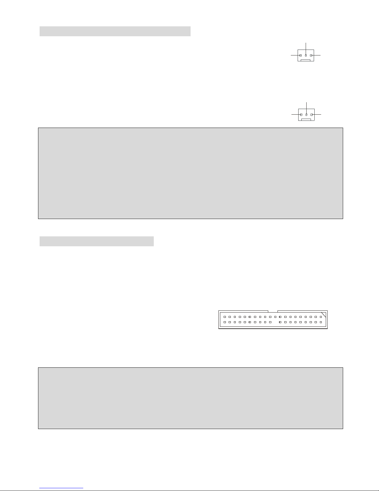
Fan Power Connectors: CPUFAN1/SYSFAN1
The CPUFAN1 (processor fan) and SYSFAN1 (system fan) support system cooling fan
with +12V . They support three-pin head connector. When connecting the wire to
the connectors, always take note that the red wire is the positive and should be
connected to the +12V, the black wire is Ground and should be connected to GND. If
the mainboard has a System Hardware Monitor chipset on-board, you must use
a specially designed fan with speed sensor to take advantage of the CPU fan control.
MSI Reminds You. ..
1. Always consult the vendors for proper CPU cooling fan.
2. CPUFAN1 supports the fan control. You can install the PC Alert utility that will automatically control
the CPU fan speed according to the actual CPU temperature.
Hard Disk Connectors: IDE1 & IDE2
The mainboard has a 32-bit Enhanced PCI IDE and Ultra DMA 33/66/100/133 controller that provides
GND
L
R
JCD1
3
2
1
VC CS
SPDIF 0
GND
GND
SEN SOR
+12
V
CPUFAN
1
GND SENSOR
+12
V
SYSFAN1
132
4
GND
GND
12V 12V
2
1
GND
CINTRO
8
PIO mode 0~4, Bus Master, and Ultra DMA 33/66/100/133 function. You can connect up to four hard
disk drives, CD-ROM, 120MB Floppy and other devices.
The first hard drive should always be connected to IDE1. IDE1 can connect a Master and a Slave drive.
You must configure second hard drive to Slave mode by setting the jumper accordingly. IDE2 can also
connect a Master and a Slave drive.
MSI Reminds You. ..
If you install two hard disks on cable, you must configure the second drive to Slave mode by setting its
jumper. Refer to the hard disk documentation supplied by hard disk vendors for jumper setting
instructions.
Front Panel Connectors: JFP1 & JFP2
The mainboard provides two front panel connectors for electrical connection to the front panel switches
and LEDs. JFP1 is compliant with Intel Front Panel I/O Connectivity Design Guide.
HDD
LED
Power
LED
Power
LED
Sp eaker
Reset
Switch
Power
Swi tch
1
1
7
9
2
2
8
10
JFP1
JFP2
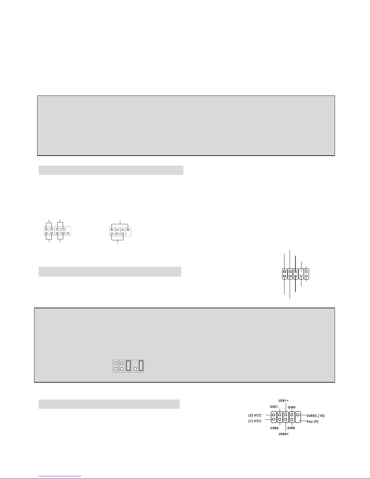
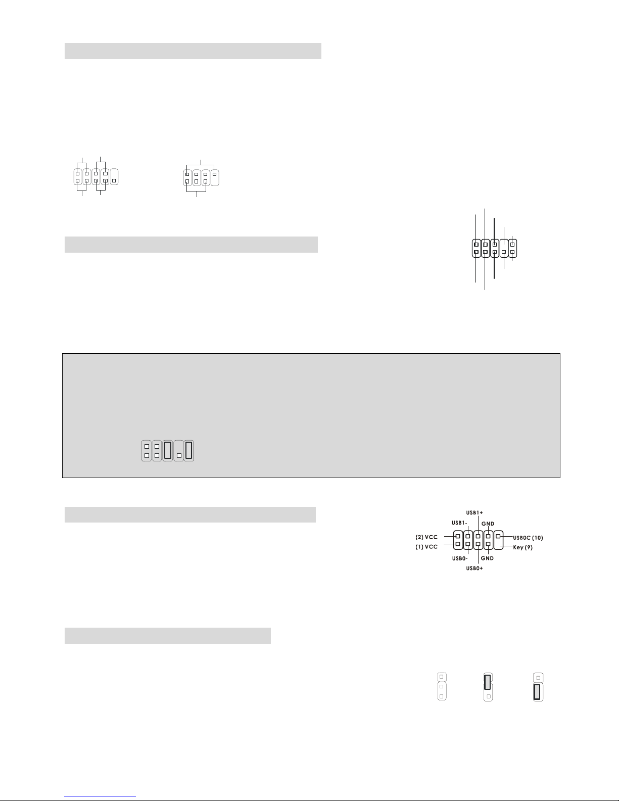
Front Panel Audio Connector: JAUD1
The JAUD1 front panel audio connector allows you to connect to the front panel
audio and is compliant with Intel ® Front Panel I/O Connectivity Design Guide.
MSI Reminds You. ..
If you do not want to connect to the front audio header, pins 5 & 6, 9 & 10 have to be jumpered in order
to have signal output directed to the rear audio ports. Otherwise, the Line-Out connector on the back
panel will not function.
1
2
9
10
Front USB Connector: JUSB1/JUSB2
The mainboard provides two USB 2.0 pin headers JUSB1 & JUSB2 that
are compliant with Intel I/O Connectivity Design Guide. USB 2.0
technology increases data transfer rate up to a maximum throughput of 480Mbps, which is 40 times
1
2
9
10
AUD_MIC
AUD_MIC_BIAS
AUD_GND
AUD_VCC
AUD_FPOUT_R
AUD_RET_L
AUD_FPOUT_L
AUD_RET_R
HP_ON
KEY

9
faster than USB 1.1, and is ideal for connecting high-speed USB interface peripherals such as USB
HDD, digital cameras, MP3 players, printers, modems and the lik e.
Clear CMOS Jumper: JBAT1
There is a CMOS RAM on board that has a power supply from external battery
to keep the data of system configuration. With the CMOS RAM, the system can
automatically boot OS every time it is turned on. If you want to clear the system confi guration, use the
JBAT1 (Clear CMOS Jumper ) to clear data. Follow the instructions to clear the data:
MSI Reminds You. ..
You can clear CMOS by shorting 2-3 pin while the system is off. Then return to 1-2 pin position. Avoid
clearing the CMOS while the system is on; it will damage the mainboard.
AGP (Accelerated Graphics Port) Slot
The AGP slot allows you to insert the AGP graphics card. AGP is an interface specification designed for
the throughput demands of 3D graphics. It introduces a 66MHz, 32-bit channel for t he graphics
controller to directly access main memory. The slot supports 8x/4x AGP card.
PCI (Peripheral Component Interconnect) Slots
The PCI slots allow you to insert the expansion cards to meet your needs. When adding or removing
expansion cards, make sure that you unplug the power supply first. Meanwhile, read the documentation
for the expansion card to make any necessary hardware or software settings for the expansion card,
such as jumpers, switches or BIOS configuration.
PCI Interrupt Request Routing
The IRQ, abbreviation of interrupt request line and pronounced I-R-Q, are hardware lines over which
devices can send interrupt signals to the microprocessor. The PCI IRQ pins are typically connected to
the PCI bus INT A# ~ INT D# pins as follows:
Order1 Order2 Order3 Order4
PCI Slot 1 INT B# INT C# INT D# INT A#
PCI Slot 2 INT C# INT D# INT A# INT B#
PCI Slot 3 INT D# INT A# INT B# INT C#
1
1
3
Keep Data
Cle ar D ata
1
3
10
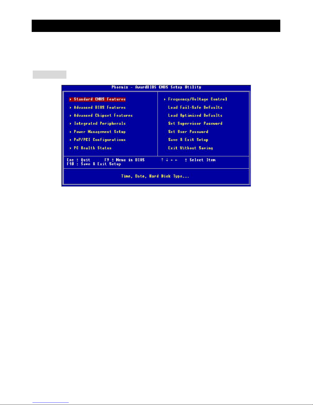
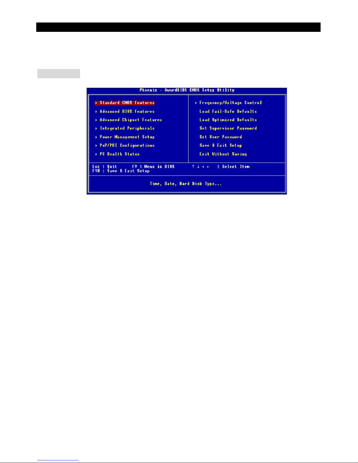
BIOS Setup
Once you enter Award®BIOS CMOS Setup Utility, the Main Menu (figure below) will appear on the
screen. The Main Menu allows you to select from twelve setup functions and two exit choices. Use
arrow keys to select among the items and press <Enter> to accept or enter t he sub-m enu.
Main Page
Standard CMOS Features
Use this menu for basic system configurations, such as time, date etc.
Advanced BIOS Features
Use this menu to setup the items of Award®special enhanced features.
Advanced Chipset Features
Use this menu to change the values in the chipset registers and optimize your system performance.
Integrated Peripherals
Use this menu to specify your settings for integrated peripherals.
Power Management Setup
Use this menu to specify your settings for power management.
PNP/PCI Configurations
This entry appears if your system supports PnP/PCI.
PC Health Status
This entry shows your PC health status.
11
Frequency/Voltage Control
Use this menu to specify your settings for frequency/voltage control.
Load Fail-Safe Defaults
Use this menu to load the BIOS values for the best system performance, but the system stability may
be affected.
Load Optimized Defaults
Use this menu to load factory default settings int o the BIOS for stable system perform ance operations.
Set Supervisor Password
Use this menu to set Supervisor Password.
Set User Password
Use this menu to set User Password.
Save & Exit Setup
Save changes to CMOS and exit setup.
Exit Without Saving
Abandon all changes and exit setup.
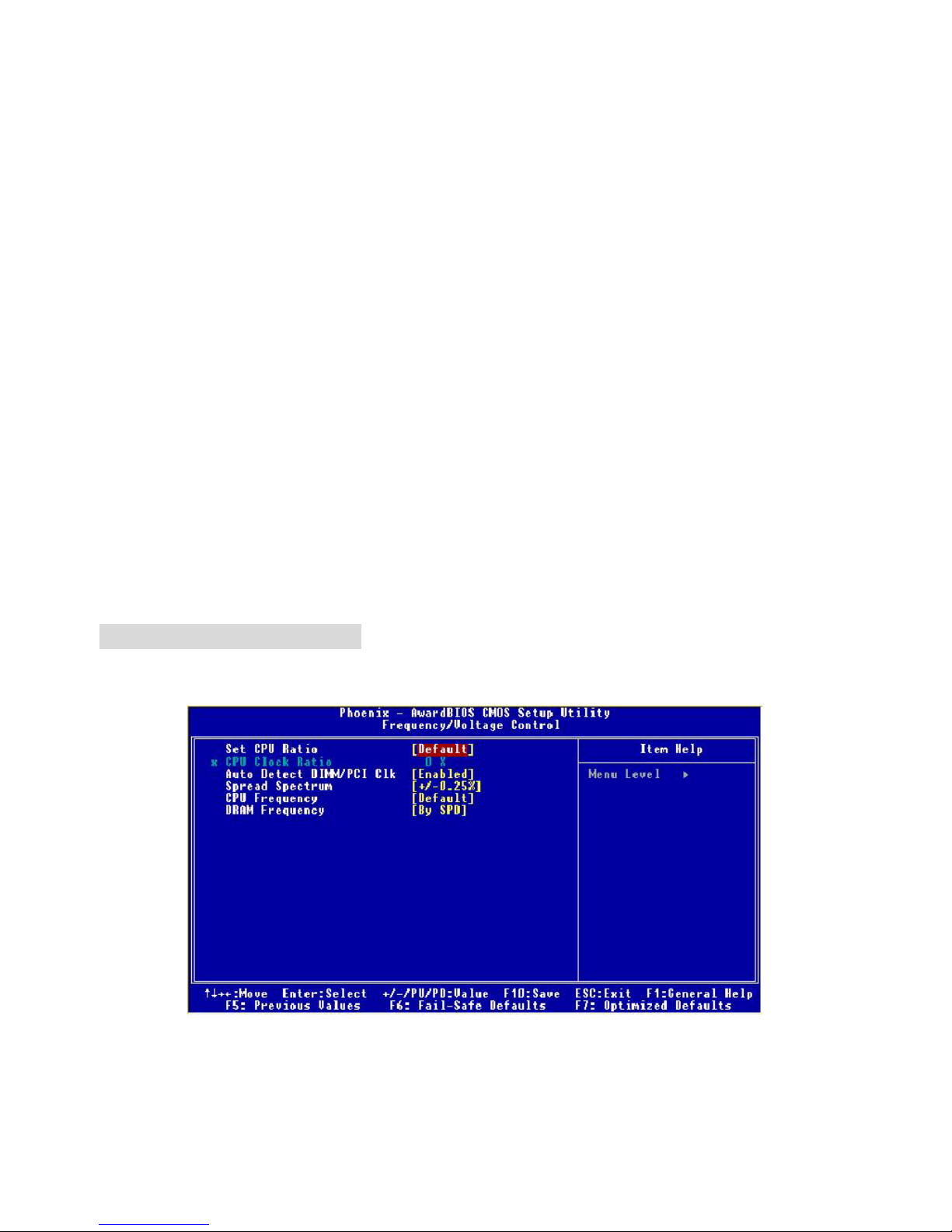
Frequency/Voltage Control
Use this menu to specify your settings for frequency/voltage control.
Set CPU Ratio
User may select to set the CPU ratio manually or use the default value of the motherboard
manufacturer. Settings: [Manual], [Default]

12
CPU Clock Ratio
End users can overclock the processor (only if the processor supports so) by specifying the CP U ratio
(clock multiplier) in this field. It is available only when Set CP U Ratio is set to [Manual].
Auto Detect DIMM/PCI Clk
This item is used to auto detect the PCI slots. When set to [Enabled], the system will remove (turn off)
clocks from empty PCI slots to minimize t he electromagnetic interference (EMI). Settings: [Enabl ed],
[Disabled].
Spread Spectrum
When the motherboard clock generator pulses, the extreme values (spikes) of the pulses creates
EMI (Electromagnetic Interference). The Spread Spectru m function reduces the EMI generated by
modulating the pulses so that the spikes of the pulses are reduced to flatter curves. If you do not have
any EMI problem, leave the setting at [Disabled] for optimal system stability and performance. But if you
are plagued by EMI, set to [Enabled] for EMI reduction. Remember to disable Spread Spectrum if you
are overclocking because even a slight jitter can introduce a temporary boost in clock speed which may
just cause your overclocked process or to lock up.
CPU Frequency
Use this item to select the appropriate clock frequency of the CPU host bus. Options are: [100MHz],
[133MHz], [Default].
DRAM Frequency
Use this item to select the appropriate frequency for your DDR SDRAM modul es. Options are:
[200MHz], [266MHz], [333MHz] and [B y SPD].

13
Einleitung
Vielen Dank für die Wahl des 651M-V Serie (MS-7005 v2.X) Micro ATX Mainboards. Die 651M-V Serie
basiert auf dem SiS ® 651 & 962L Chipsatz für optimale Systemeffizienz. Es wurde für den
fortgeschrittenen Intel ® Pentium ® 4 Prozessor im 478 Pin Sockel entwickel t und st el lt ei ne schnel l e
und proffessionelle Desktop Platform dar.
Layout
BATT
+
Si S
962L
SiS 651
D
D
R
1
D
D
R
2
JA UD1
A
T
X
P
o
w
e
r
S
u
p
p
l
y
S
Y
S
F
A
N
1
CP UF AN1
JFP 1
JFP2
Codec
Real tek
8201B L
Winbond
W83697HF
BIOS
PCI Slot 3
PCI Slot 2
PCI Slot 1
I
D
E
2
F
D
D
1
I
D
E
1
ATX 12V
Top : m ouse
Bottom: keyboard
T: LAN jack
B: USB ports
JCD1
AGP Slot
JC I1
JUSB1
JUSB2
JB AT1
JSP1
Top : Parallel Port
Bottom:
COM A
VGA Port
Top :
Game port
Bottom:
Mic
Line-Out
Line-In

14
Spezifikationen
CPU
z Sockel 478 für P4 Prozessoren (Northwood/Prescott ) mit 400 MHz/533 MHz FSB.
z Unterstützt bis zu 3.06GHz und schnellere CPUs.
z Unterstützt Hyper-Threading CPUs.
(Für die neuesten CPU-Kompatiblitäts-Informationen besuchen Sie bitte die folgende Webseite:
http://www.msi.com.tw/program/products/mainboard/mbd/pro_mbd_cpu_support.php
)
Chipsatz
z SiS 651 (702 pin BGA)
- Hochgeschwindigkeits-CPU-Schnittstell e mit 400 MHz/533 MHz
- 64 Bit Hochgeschwindigkeits-Speicherkontroller für DDR200/266/333 Speicher integriert
- Unterstützt AGP 4X/2X Schnittstelle mit beschlrunigten Schreibzugriffen
- Hoher Durchsatz mit SiS MuTIOL Verbindung zum SiS962L MuTIOL Media I/O Chip
- hochgeschwindigkeits 2D/3D- und Video-Beschleuniger
z SiS 962L MuTIOL Media I/O (371BGA)
- Hochgeschwindigkits-MuTIOLzur SiS Northbridge
- Integrierte Multi-Threaded I/O Verbindung um gleichzeitige up/down Stream-Daten Transfers mit
1.2GB/s Nabdbreite sicherzustellen.
- Intergrierter USB 2.0/1.1 Host Kontroller und Fast Ethernet MAC Kontroller
- Intergrierter Audio Kontroller mit AC97 Interface
- Erweitertes Power Management und PC2001 Entsprechung
- Intergrierter RTC, DMA, Interrupt, und keyboard Kontroller
- Intergrierte PCI nach LPCC Brücke
Hauptspeicher
z Unterstützt zwei Speicherbänke für zwei 184-Pin ungepufferte DDR 200/266/333 DIMMs
z Unterstützt bis zu 2GB Speichergröße ohne ECC
(Für die neuesten CPU-Kompatiblitäts-Informationen besuchen Sie bitte die folgende Webseite:
http://www.msi.com.tw/program/products/mainboard/mbd/pro_mbd_cpu_support.php
)
Erweiterungssteckplätze
z Ein AGP (Accelerated Graphics Port) Steckplatz mit AGP 2.0 4X/2X Unterstützung
z Drei PCI 2.2 32-Bit Master PCI Bus Steckplätze (unterstützt 3.3V/5V PCI Schnittstelle)

15
On-Board IDE
z Dual IDE Kontroller intergriertert in SiS 962L
z Unterstützt Bus Master, Ultra DMA 33/66/100/133 Operatio nsm o dus
z Es können bis zu vier IDE Laufwerk e ange schlossen werden
On-Board Peripherie
z On-Board Peripherie beinhaltet:
- 1 Floppy Anschluss, unterstützt 2 Floppy mit 360K, 720K, 1.2M, 1.44M und 2.88Mbytes.
- 1 Serieller Anschluß (COMA) und 1 VGA Anschluss
- 1 Paralleler Anschluß, unterstützt SPP/EPP/ECP Modus
- 6 USB 2.0 Anschlüsse (Rückseite * 2/ Front * 4)
- 1 Audio-Ein/Ausgang und Mikrofon-Anschluss
- 1 Joystick-Anschluss
- 1 RJ45 Netzwerkanschluss
Audio
z AC97 Audio-Kontroller intergriert in SiS 962L SB
z 6 Kanal Software Audio Codec Realtek ALC655
- Entspricht den AC97 v2.2 Spezifikationen und den PC2001 Audio Anforderungen.
Netzwerk
z SiS 962L intergrierter MAC + Realtek 8201BL PHY
- Unterstützt 10Mb/s und 100Mb/s mit automtischer Erkennung.
- Entspricht dem PCI 2.2 und PC99 Standard
z Unterstützt Wake-On-LAN und Remote Wake-up
z Unterstützt ACPI Power Management
BIOS
z 4MB Award BIOS mit PNP BIOS, ACPI, SMBIOS 2.3, Green und Boot Block
z Stellt DMI 2.0, WFM 2.0, WOL, WOR, Chassis Intrusion und SMBus for system management zur
Verfügung
Dimension
z Micro-ATX Form Factor: 24.5 cm (B) x 20.0 cm (T)
Befestigung
z 6 Befestigungslöcher
Andere
z Live BIOS/Live Driver Update
z Entspricht den PC2001 Empfehlungen
z Suspend to RAM / Disk
16
Anschlüsse auf der Rückseite
Folgende Anschlüsse stehen auf der Rückseite zur Verfügung:
Mou se
Keyboa rd
Para llelPara llel
COMA
VGA Port
L-out L-in MI C
Midi/Joystick
LANLAN
USB Ports
Hardware Einrichtung
Dieses Kapitel beschreibt Ihnen, wie CPU, Spei chermodule und Erweiterungskarten eingesetzt werden,
und wie Jumper auf dem Mainboard eingestellt werden. Es beinhaltet auch die Anleitung, wie Sie
Peripheriegeräte wie Maus, Tastatur, usw. anschließen. Während der Installation behandeln Sie bitte
die Komponenten vorsichtig und folgen Sie genau der Anleitung.
Prozessor
Das Mainboard unterstützt Intel Pentium 4 Northwood & Prescott und Celeron Prozess oren i n der
Sockel 478 Bauform. Dazu hat es einen PGA478 Sockel für die leichte CPU Installation. Um den
Prozessor vor Überhitzung zu schützen, stellen Sie sicher, dass Sie einen geeigneten
CPU-Kühler mit Lüfter auf dem Prozessor installieren. W enn Sie keinen geeigneten Kühler für
Ihren Prozessor haben sollten, kontaktieren Sie Ihren Händler, um ein passendes Modell erwerben.
Bitte schalten Sie den PC nicht ein, wenn Sie keinen geeigneten Kühler installiert haben. (Für die
neuesten CPU-Kompatiblitäts- Informationen besuchen Sie bitte die folgende Webseite:
http://www.msi.com.tw/program/products/mainboard/mbd/pro_mbd_cpu_support.php
)
Beispiel für die Einstellung des internen CPU-Taktes
Wenn CPU Takt = 133MHz
Taktmulti
p
likator=23
dann CPU Kerntakt = Ext. Takt x Taktmulti
p
likato
r
= 133MHz x 23
= 3.06 GHz

17
Memory Speed/CPU FSB Support Matrix
Speicher
FSB
DDR 266 DDR 333
400MHz OK OK
533MHz OK OK
CPU Installationsprozedur für Sockel 478
1. Bitte schalten Sie den PC aus und ziehen das Netzkabel ab, bevor Sie die CPU einsetzen.
2. Klappen Sie den Hebel am CPU-Sockel auf. Stellen Sie sicher, dass er im 90 Grad Winkel
aufgeklappt ist.
3. Sehen Sie den goldenen Pfeil an der CPU?. Dieser Pfeil muss zum Hebelmechanismus des
Sockels zeigen. Die CPU darf nur in der richtigen Richtung einges etzt werden.
4. Sobald die CPU richtig eingesetzt ist, sind die Anschlussbeine der CPU komplett im Sockel
eingesteckt. Das Einsetzen erfolgt ohne Kraftanwendung. Bitte beachten Si e, dass eine falsc he
Installation des Prozessors Ih r Mainboard und Ihren P rozessor beschädigen können.
5. Drücken Sie noch mal auf die CPU und klappen dann den Hebel herunter. Während Sie den
Hebel herunterklappen, bewegt sich die CPU noch ein wenig nach vorne. Der Hebel ist in der
Endposition, wenn er fühlbar einrastet. Der Hebel lässt sich sehr leicht bewegen. Wenn es
klemmt, prüfen Sie nochmals den korrekten Sitz der CPU.
Installation des CPU-Kühlers
Da die Prozessortechnologie sich mit großen Schritten bei den Taktraten und der
Arbeitsgeschwindigkeit weiterentwickelt, wird die effiziente Prozessorkühluung immer wichtiger. Um die
Wärme abzuführen, müssen Sie einen CPU-Kühler mit Lüfter auf die CPU aufsetzen. Folgen Sie der
Anleitung, um den Kühler auf die CPU aufzusetzen.:
1. Lokalisieren Sie die CPU und den Befestigungsrahmen für den Kühler auf dem Mainboard.
2. Setzen Sie den Kühler in den Rahmen ein.
3. Falls erforderlich, befestigen Sie den Lüfter auf dem Kühler. Beachten Sie dabei die
Montagehinweise des Kühlerherstellers. Drücken Sie den Kühler in den Rahmen, bis er
einrastet..
4. Drücken Sie die beiden Hebel des Kühlers herungter, bis sie einrasten. Bitte beachten Sie dabei
18
die Hinweise des Kühlerherstellers.
5. Schliessen Sie das Versorgungskabel des Lüfters an dem 3-poligen Anschluss des Mainboards
an.
Speicher
Das Mainboard stellt zwei 184-Pin ungepufferte DDR200/DDR266/DDR333 DDR SDRAM Sockel zur
verfügung, und unterstützt eine maximale Speichergröße von bis zu 2GB. . Damit das System
funktioniert, muss wenigstens ein DIMM eingeset zt werden.
(Für die neuesten Speicher-Kompatiblitäts-Informationen besuchen Sie bitte die folgende Webseite:
http://www.msi.com.tw/program/products/mainboard/mbd/pro_mbd_trp_list.php
)
Speichermodule können in beliebiger Reihenfolge installiert werden. Sie können sowohl einseitige als
auch zweiseitige Module verwenden.
DDR Modules einsetzen
1. Das DDR DIMM Modul hat in der Mitte eine Nase, die verhindern soll, dass Sie das Modul in der
falschen Richtung einsetzen.
2. Setzen Sie das Modul senkrecht in den Sockel ein, bis die goldenen Kontakte komplett im
Sockel versinken.
3. Die weißen Verriegelungshebel an der Seite schließen sich automatisch und rasten
ein.
NotchVol
t
MSI erinnert Sie...
Überhitzung…
Überhitzung beschädigt Ihre CPU und ds gesamte Syst em ernsthaft, stel l en Sie daher sicher, dass die
Lüfter immer funktionieren, um die CPU und das System vor Schäden zu bewahren.
Die CPU tauschen…
19
Wenn Sie die CPU tauschen, schalten Sie das System ab und ziehen den Netzstecker. Bevor Sie das
Mainboard oder die CPU anfassen, erden Sie sich, in dem Sie kurz geerdeten Gegenstand (z.B.
Heizung) berühren. Dadurch vermeiden Sie Defekte an der Hardware durch statische Aufladung.
Netzteil
Das Mainboard unterstützt ATX Netzteile für die Stromversorgung. Befor Sie das System einschalten,
vergewissern Sie sich, dass alle Komponent en richti g eingesetzt wurden, damit das System nicht
beschädigt werden kann.
ATX 20-Pin Power Anschluss: CONN1
An diesem Anschluss schließen Sie das Netzteil an. Der Netzteilstecker
lässt sich nur in einer Richtung einstecken. Drücken Sie den Stecker in
den Anschluss, bis er einrastet.
ATX 12V Power Anschluss: ATX12V
Dieser 12V Stromanschluss versorgt die CPU mit Strom. Auch dieser Stecker lässt
sich nur in eine Richtung einsetzen..
Floppy Disk Laufwerk Anschluss: FDD1
Das Mainboard stellt einen Floppyanschluss zur Verfügung,
an dem bis zu zwei Laufwerke mit 360K, 720K, 1.2M, 1.44M
und 2.88M Kapazität angeschlossen werden können.
Chassis Intrusion Sensor Anschluss: JCI1
Diesen Anschluss kann für einen zweipoligen Chassis Intrusion Sensor verwendet werden. Wenn das
gehäuse offen ist, dann ist der Schalter geschlossen. Das Mainboard zeichnet diesen Status auf.. Um
die Warnmeldung zu löschen, müssen Sie in das BIOS und dort den Status
löschen.
CD-Audio-Eingang: JCD1
Hier können Sie das Audiokabel Ihres CD-Laufwerks anschließen.
SPDIF-OUT Connector: JSP1
Dieser Anschluss ist für einen SPDIF (Sony & Philips Digital Interconnect Format)
Adapter für digitale Audio-Übertragung vorgesehen.
GND
L
R
JCD1
3
2
1
VC CS
SPDIF 0
GND
1
11
3.3V
3.3V
3.3V
-12V
GND
GND
GND
GND
GND
GND
GND
PW_OK
-5V
5V_SB
5V
5V
12 V
5V
PS_O N
5V
10
20
132
4
GND
GND
12V 12V
2
1
GND
CINTRO
20
Lüfteranschlüsse: CPUFAN1/SYSFAN1
Der CFAN1 (CPU-Lüfter) und SFAN1 (System Lüfter) untesrtützen Lüfter mit
+12V Betriebsspannung. Diese müssen einen dreipüoligen Anschluss haben.
Beim Anschliessen beachten, dass das rote Kabel im Stecker immer mit dem 12-Anschluss des
Steckers, der schwarze mit Masse des Steckers verbunden wird. Da das Mainboard mit Hardware
monitor ausgestattet ist, müsen Sie spezielle Lüfter mit Speed-Signal verwenden,
damit die Lüftergeschwindigkeit ausgewertet und gesteuert werden kann .
MSI erinnert Sie...
1. Verwenden Sie stets einen geeigneten CPU-Lüfter und beachten Sie die Einbauhinweise in diesem
Handbuch und in der Lüfterdokumentation.
2. CPUFAN1 unterstützt die Geschwindigkeitsregelung des Prozessorlüfters. Sobald Sie von der
Treiber-CD das Windows-Programm PC-Alert installiert haben, wird diese Regelung aktiviert.
PC-Alert regelt die Lüfterdrehzahl anhand der CPU-Temperatur.
IDE Anschlüsse: IDE1 & IDE2
Das Mainboard hat einen 32-bit erweiterten PCI IDE und Ultra DMA 33/66/100/133 Controller, welcher
die PIO Modis 0~4, Bus Master, und Ultra DMA 33/66/100/133 Funktion zur Verfügung stellt. Sie
können bis zu vier IDE-Festplatten, CD-ROM, 120MB Floppys und andere Geräte anschließen.
IDE1 (Primä r e r ID E An s c h lus s ) :
Das erste Laufwerk sollte an IDE1 angeschlossen werden.
IDE1 unterstützt Master und Slave-Laufwerke.
IDE2 (Sekundärer IDE Anschluss): IDE2 unterstützt Master und Slave Laufwerke.
MSI erinnert Sie...
Wenn Sie zwei IDE-Laufwerke an einem IDE-Kabel anschließen, so müssen Sie das erste Laufwerk
als Master und das zweite Laufwerk als Slave konfigurieren. Sie erfahren aus der Dokumentation der
Laufwerke, wie diese Einstellung gemacht wird.
GND
SEN SOR
+12
V
CPUFAN
1
GND SENSOR
+12
V
SYSFAN1
21
Gehäusefront-Anschlüsse: JFP1 & JFP2
Das Mainboard hat Anschlüsse für Bedienelemente und Statusanzeigen an der Vorderseite des
gehäuses. Hierzu gehören Anzeige LEDs und Taster. JFP1 entspricht dem “Intel Front Panel I/O
Connectivity Design Guide“.
HDD
LED
Power
LED
Power
LED
Sp eaker
Reset
Switch
Power
Swi tch
1
1
7
9
2
2
8
10
JFP1
JFP2
Gehäusefront A udio-Anschluss: JAUD1
Der JAUD1 Gehäusefront-Anschluss erlaubt es Ihnen, Audio-Anschlüsse an der
Vorderseite Ihres Gehäuses mit dem Mainboard zu verbinden. Der Anschluss
entspricht dem “Intel ® Front Panel I/O Connectivity Design Guide”
.
MSI erinn e rt Sie...
Wenn Sie diesen Audioanschluss nicht verwenden möchten, so müssen die Kontakte 5 & 6, 9 & 10
jeweils mit einem Jumper geschlossen sein, damit der hintere Audio-Ausgang des Mainboards
funktioniert..
1
2
9
10
Front USB Anschlüsses: JUSB1/JUSB2
Das Mainboard stellt einen UHCI (Universal Host Controller Interface)
Universal Serial Bus Kontroller für den Anschluß von USB Geräten wie
Tastatur , M aus und andere US B kompa tible Geräte zur Verfügung Stecken Sie an diesen Anschluss
den Adapter mit den üblichen USB-Steckern an.
CMOS Rücksetz-Jumper: JBAT1
Im Mainboard ist ein CMOS Speicher integriert, welches von einer Batterie versorgt wird, um die
Systemkonfiguration zu speichern. Das CMOS RAM ermöglicht es, das
System automatisch zu starten, ohne dass die Konfiguration neu eingestel lt
werden muss. Wenn Sie die CMOS-Konfiguration löschen wollen, setzen Sie im ausgeschalteten
1
2
9
10
AUD_MIC
AUD_MIC_BIAS
AUD_GND
AUD_VCC
AUD_FPOUT_R
AUD_RET_L
AUD_FPOUT_L
AUD_RET_R
HP_ON
KEY
1
1
3
Keep Data
Cle ar D ata
1
3

22
Zustand den Jumper JBAT1 von Position 1-2 auf 2-3 um.
MSI erinn e rt Sie...
Schalten Sie den PC vor dem Umsetzen des Jumpers aus. Setzen Sie den Jumper nach ein paar
Sekunden wieder in 1-2 zurück und schalten erst dann den PC wieder ein.
AGP (Accelerated Graphics Port) Steckplatz
In den AGP Steckplatz können Sie eine AGP-Grafikkarte einsetzen. AGP ist eine Schnittstelle, deren
Spezifikation für den Datendurchsatz von schnellen 3D-Grafuikkarten entwickelt wurde. AGP
ermöglicht 66MHz, 64-Bit Datenübertragung für den Grafik -Kontroller direkt zum Hauptspeicher. Das
Mainboard unterstützt AGP-Grafikkarten mit 4x/8x Übertragung.
PCI (Peripheral Component Interconnect) Steckplätze
Ein PCI Steckplatz erlaubt es Ihnen, für Sie erforderliche
PCI-Erweiterungskarten in das System einzusetzen. Wenn Sie Erweiterungskarten einsetzen oder
entfernen, stellen Sie sicher, dass Sie vorher den PC ausschalten und den Netzstecker abziehen.
Lesen Sie auch die Dokumentation der Erweiterungskarte bezüglich Hinweisen des Herst el l ers zum
Einbau und möglichen Hardware- und Softwareeinstellungen.
PCI Interrupt Verteilung
Die IRQs, Abkürzung für Interrupt Request, sind Hardwaresignale, über welche Peripheriegeräte dem
Prozessor Interrupt-Signale zus e nden können, wenn sie Aufmerksamkeit des Prozessors brauchen.
Die PCI IRQ Signale sind üblicherweise auf dem PCI-Bus mit den Signalen INT A# ~ INT D# wie folgt
verbunden:
Reihenfolge 1 Reihenfloge 2 Reihenfolge 3 Reihenfolge 4
PCI Steckplatz 1 INT B# INT C# INT D# INT A#
PCI Steckplatz 2 INT C# INT D# INT A# INT B#
PCI Steckplatz 3 INT D# INT A# INT B# INT C#
23
BIOS Setup
Sobald Sie das Award®BIOS CMOS Setup Utility öffnen, wird das abgebildete Hauptmenü auf dem
Monitor angezeigt. Dieses Hauptmenü bietet Ihnen di e Auswahl von 12 Untermenüs mit
Systemeinstellungen. Sie können sich mit den Pfeiltasten durch die Menüstruktur bewegen. Die
Eingabetaste wählt einen Menüpunkt aus,
Hauptmenü
Standard CMOS Features
Hier können Sie die Grundeinstellungen wie Laufwerke, Dastum, Uhrzeit ei nst e l l en.
Advanced BIOS Features
Hier stellen Sie erweiterte Einstellungen des Award-BIOS ein.
Advanced Chipset Features
Hier stellen Sie Chipsatzregister ein und können die Systemperformance optimi eren.
Integrated Peripherals
Hier können Sie Einstellungen zu Peripheriegerätetn vornehmen.
Power Management Setup
Hier können Sie Energieoptionen einstellen.
PNP/PCI Configurations
Dieser Eintrag wird angezeicht, wenn Ihr System PnP/PCI unterstützt .
PC Health Status
Dieses Untermenü zeigt Ihnen die Hardwareüberwachung I hres Systems an.
Frequency/Voltage Control
Hier können Sie Frequenzen und Betriebsspannungen einstellen.
Load Fail-Safe Defaults
Dies ist eine Voreinstellung für ein langsammes aber extrem stabiles und kompatibles System.
Load Optimized Defaults
Dies ist eine Voreinstellung für eine optimale Systemperformance bei hoher Stabilität und
Kompatibilität.
Set Supervisor Password
Hier können Sie ein Supervisor-Passwort einst el l en.
Set User Password
Hier können Sie ein Benutzerpasswort einstellen.
 Loading...