

Page 1

Getting Started
1-1
Chapter 1. Getting Started
1
Getting Started
Thank you for purchasing the MS-6577 v2.X Micro ATX mainboard.
The MS-6577 is based on Intel® Brookdale-G/GE & ICH4 chipsets for optimal
system efficiency. Designed to fit the advanced Intel® P4 Williamette and
Northwood processors in 478-pin package, the MS-6577 delivers a high performance and professional desktop platform solution.
TOPICS
Mainboard Specification 1-2
Mainboard Layout 1-4
Quick Components Guide 1-5
Page 2

Chapter 1
1-2
CPU
h Supports Socket 478 for Intel® P4 Williamette and Northwood processors.
h Supports 1.4GHz to 2.8GHz or higher speed.
Chipset
h Intel® 845G/GE chipset
- FSB 400/533MHz.
- Multiplexed AGP interface.
- Integrated 3D/2D graphic core.
- Supports DDR 333 (for 845GE only)/266/200 memory.
h Intel® ICH4 chipset
- Hi-Speed USB (USB2.0) controller, 480Mb/sec.
- AC’97 3 Codec supported.
- Supports both ACPI and legacy APM power management.
Main Memory
h Supports four memory banks using two 184-pin unbuffered DIMM.
h Maximum memory size is 2GB without ECC (1GB/slot).
h Supports 2.5V DDR DIMM.
Slots
h Three 32-bit Master PCI (Peripheral Component Interconnect) Bus slots.
h One AGP (Accelerated Graphics Port) slot.
Onboard IDE
h An IDE controller on the ICH4 chipset provides IDE HDD/CD-ROM with
PIO, Bus Master and Ultra DMA100/66 operation modes.
h Can connect up to four IDE devices.
Onboard Peripherals
h Onboard peripherals include:
- 2 PS/2 Ports
- 6 USB Ports (Rear x 4 /Front x 2)
- 1 Parallel Port + 1 Serial Port + 1 VGA Port
- 2 IEEE1394 Ports (Rear x 1 /Front x 1)
Mainboard Specification
Page 3

Getting Started
1-3
- 1 RJ-45 LAN Port
- Vertical Audio Ports (Line_in, Line_out, Mic_in)
- IDE x 2 (A TA100), Floppy x 1, ATX power connector
- AUX_IN x 1/ MIC_IN x 1
- MSI S-Bracket connector x 1
- Internal speaker pinheader x 1
- Front panel pinheader x 1
- CPU_F AN x 1/ SYS_F AN x 1
- Clear password pinheader x 1
- Clear CMOS pinheader x 1
Audio
h AC’97 link controller integrated in ICH4.
h Six-channel software codec RealT ek ALC 650 (Optional).
LAN
h RealTek R TL8101L chip
- Integrated Fast Ethernet MAC and PHY in one chip.
- Supports 10 Mb/s and 100 Mb/s.
- Compliance with PCI v2.2.
- Supports ACPI Power Management.
BIOS
h PnP (Plug & Play) BIOS to detect peripheral devices and expansion cards
automatically.
h DMI (Desktop Management Interface) function to record motherboard
specifications.
Dimension
h Micro-ATX Form Factor: 9.6" x 9.1"
Mounting
h 6 mounting holes.
Page 4

Chapter 1
1-4
BATT
+
Intel
ICH4
BIOS
AGP Slot
A
T
X
P
o
w
e
r
S
u
p
p
l
y
C_FAN1
P
R
I
M
A
R
1
S
E
C
O
N
1
JAUX1
JCD1
JSP1
JFMIC
JSPD2
S_FAN1
Winbond
W83627HF-AW
RealTek
RTL8101L
Top:
Parallel Port
Bottom:
COM A
VGA Port
JPW2
F
D
D
1
PCI Slot 1
PCI Slot 3
PCI Slot 2
Top: mouse
Bottom: keyboard
T: 1394 port
B: USB ports
D
D
R
1
D
D
R
2
JPWD1
JBAT1
Intel
845G/GE
Chipset
Line-In
Line-Out
Mic
T: LA N jac k
B: USB ports
Mainboard Layout
MS-6577 v2.X Micro A TX Mainboard
MSI Reminds Y ou...
Enabling the functionality of Hyper-Threading Technology for
your computer system requires ALL of the following platform
Components:
*CPU: An Intel® Pentium® 4 Processor with HT Technology;
*Chipset: An Intel® Chipset that supports HT Technology;
*BIOS: A BIOS that supports HT T echnology and has it enabled;
and
*OS: An operating system that supports HT Technology.
For more information on Hyper-threading Technology, go to:
http://www.intel.com/info/hyperthreading
Page 5

Getting Started
1-5
Quick Components Guide
Component Function Reference
Socket 478 Installing CPU See p. 2-2
DDR1~2 Installing DDR modules See p. 2-6
ATX Power Connector Installing power supply See p. 2-8
IEEE 1394 Port Connecting to 1394 devices See p. 2-10
USB Ports Connecting to USB devices See p. 2-10
COM A Serial port connector See p. 2-11
VGA Connector Connecting to VGA monitors See p. 2-11
LPT1 Parallel port connector See p. 2-12
RJ-45 LAN Jack Connecting to LAN devices See p. 2-13
FDD1 Floppy disk drive connector See p. 2-14
JSP1 Internal speaker connector See p. 2-14
PRIMAR1/SECON1 Hard disk connectors See p. 2-15
JCD1 CD-in connector See p. 2-16
JAUX1 AUX-in connector See p. 2-16
C_FAN1/S_FAN1 Fan power connectors See p. 2-17
JFP1 Front panel connector See p. 2-18
JUSB1 Front USB connector See p. 2-19
JFMIC Front microphone connector See p. 2-20
JSPD2 S-Bracket connector See p. 2-21
J1394_2 IEEE 1394 connector See p. 2-22
JBAT1 Clear CMOS jumper See p. 2-23
JPWD1 Clear BIOS password jumper See p. 2-24
AGP Slot Connecting to VGA cards See p. 2-25
PCI Slots Connecting to expansion cards See p. 2-25
Page 6

Hardware Setup
2-1
Chapter 2. Hardware Setup
TOPICS
Central Processing Unit: CPU 2-2
Memory 2-6
Power Supply 2-8
Back Panel 2-9
Connectors 2-14
Jumpers 2-23
Slots 2-25
2
Hardware Setup
This chapter provides you with the information about hardware setup
procedures. While doing the installation, be careful in holding the components
and follow the installation procedures. For some components, if you install in
the wrong orientation, the components will not work properly.
Use a grounded wrist strap before handling computer components. Static
electricity may damage the components.
Page 7

Chapter 2
2-2
Central Processing Unit: CPU
CPU Core Speed Derivation Procedure
If CPU Clock = 100MHz
Core/Bus ratio = 1 4
then CPU core speed = Host Clock x Core/Bus ratio
= 100MHz x 14
= 1.4 GHz
The mainboard supports Intel® Pentium® 4 processor in the 478 pin
package. The mainboard uses a CPU socket called PGA478 for easy CPU
installation. When you are installing the CPU, make sure the CPU has a heat
sink and a cooling fan attached on the top to prevent overheating. If you do not
find the heat sink and cooling fan, contact your dealer to purchase and install
them before turning on the computer.
MSI Reminds Y ou...
Overheating
Overheating will seriously damage the CPU and system, always make sure the cooling fan can work properly to protect
the CPU from overheating.
Replacing the CPU
While replacing the CPU, always turn off the ATX power supply or unplug the power supply’s power cord from grounded
outlet first to ensure the safety of CPU.
Page 8
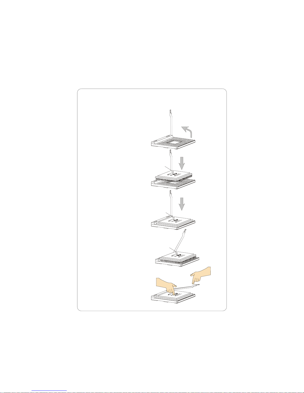
Hardware Setup
2-3
1. Please turn off the power and
unplug the power cord before
installing the CPU.
2. Pull the lever sideways away
from the socket. Make sure to
raise the lever up to a 90-degree angle.
3. Look for the gold arrow. The
gold arrow should point towards the lever pivot. The
CPU can only fit in the correct
orientation.
4. If the CPU is correctly
installed, the pins should be
completely embedded into the
socket and can not be seen.
Please note that any violation
of the correct installation procedures may cause permanent
damages to your mainboard.
5. Press the CPU down firmly into
the socket and close the lever.
As the CPU is likely to move
while the lever is being closed,
always close the lever with
your fingers pressing tightly
on top of the CPU to make sure
the CPU is properly and completely embedded into the
socket.
CPU Installation Procedures for Socket 478
Open Lever
90 degree
Sliding
Plate
Close
Lever
Press down
the CPU
Gold arrow
Gold arrow
Gold arrow
Correct CPU placem ent
Incorrect CPU place men t
X
O
Page 9
Chapter 2
2-4
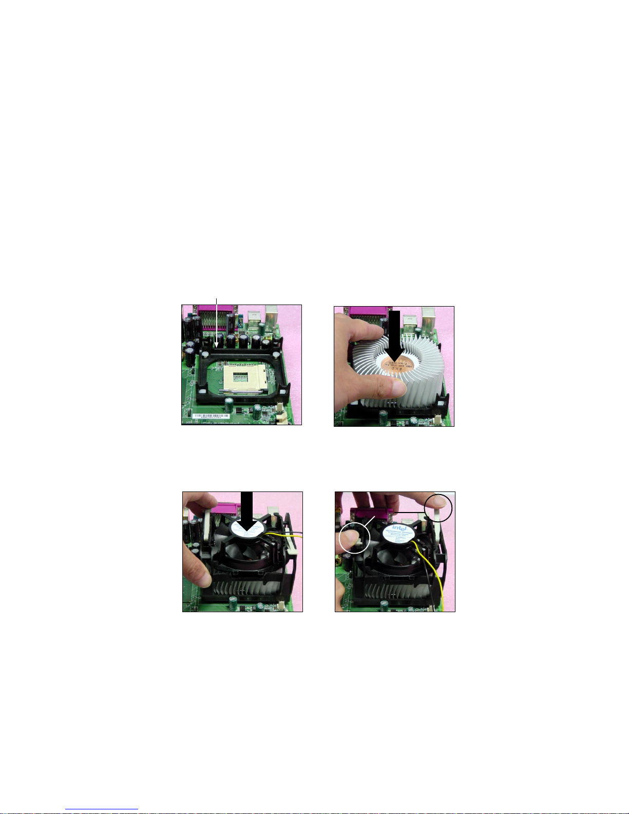
Installing the CPU Fan
As processor technology pushes to faster speeds and higher
performance, thermal management becomes increasingly important. To dissipate heat, you need to attach the CPU cooling fan and heatsink on top of the
CPU. Follow the instructions below to install the Heatsink/Fan:
2. Position the heatsink onto the reten-
tion mechanism.
1. Locate the CPU and its retention
mechanism on the motherboard.
3. Mount the fan on top of the heatsink.
Press down the fan until its four clips
get wedged in the holes of the retention mechanism.
4. Press the two levers down to fasten
the fan. Each lever can be pressed
down in only ONE direction.
retention mechanism
levers
Page 10
Hardware Setup
2-5
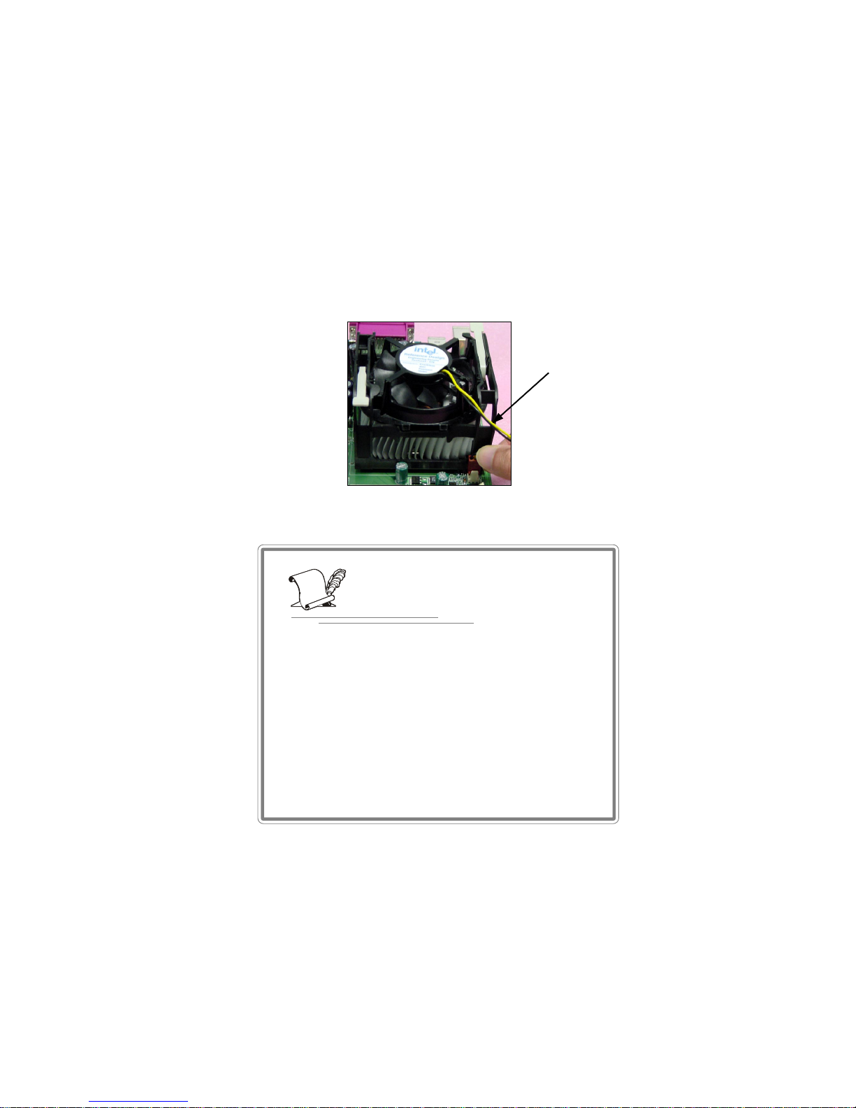
5.
Connect the fan power cable from the mounted fan to the 3-pin fan power connector
on the board.
fan power cable
NOTES
Page 11
Chapter 2
2-6
Memory
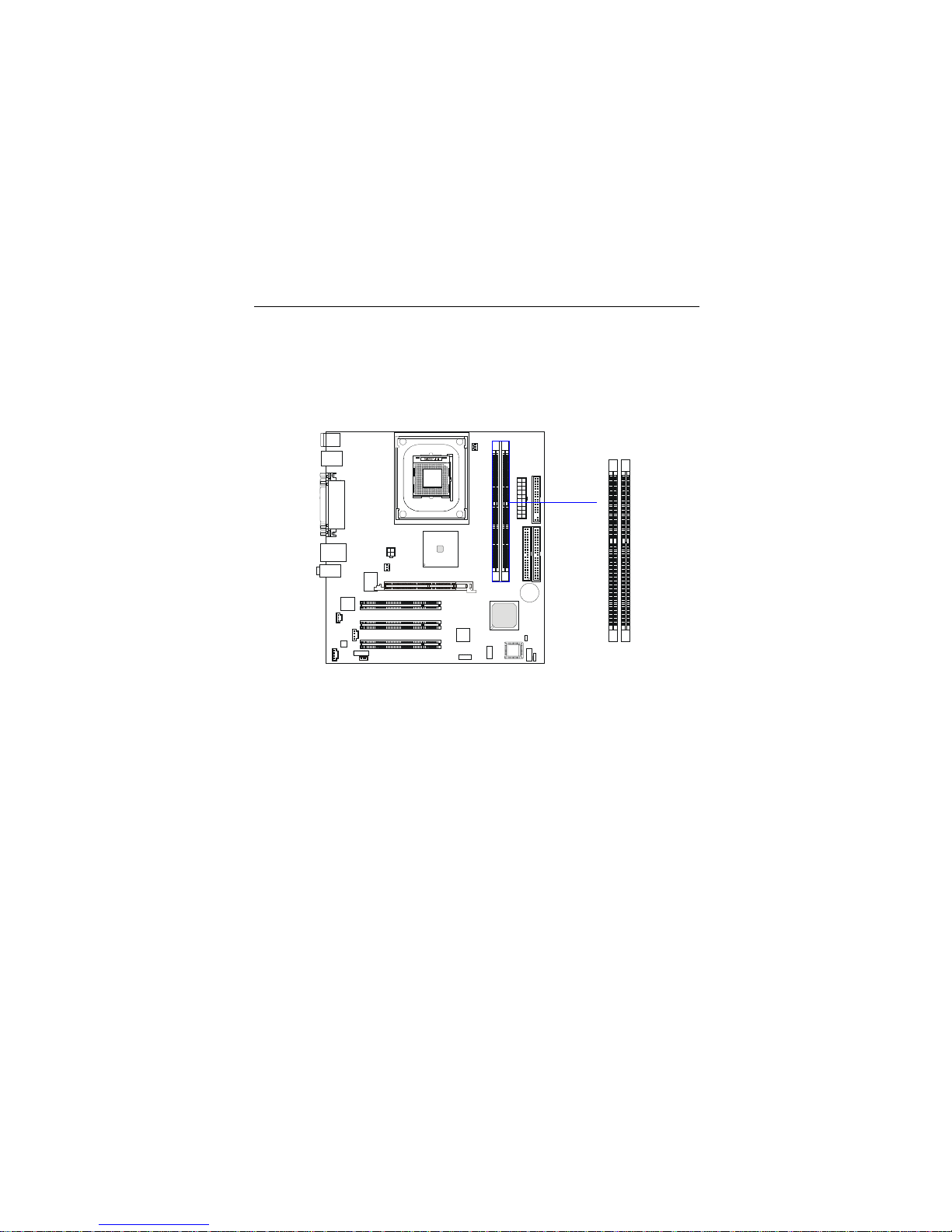
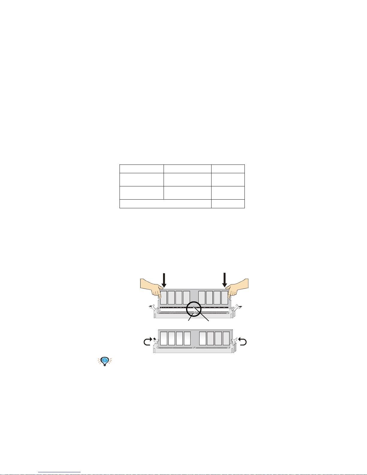
The mainboard provides 2 slots for 184-pin, 2.5V DDR DIMM with 4
memory banks. You can install DDR333/PC2700 (for 845GE chipset only),
DDR266/PC2100, or DDR200/PC1600 DDR SDRAM modules on the DDR DIMM
slots (DDR 1~2). To operate properly, at least one DIMM module must be
installed.
Introduction to DDR SDRAM
DDR (Double Data Rate) SDRAM is similar to conventional SDRAM,
but doubles the rate by transferring data twice per cycle. It uses 2.5 volts as
opposed to 3.3 volts used in SDR SDRAM, and requires 184-pin DIMM modules rather than 168-pin DIMM modules used by SDR SDRAM. High memory
bandwidth makes DDR an ideal solution for high performance PC, workstations and servers.
DDR1
DDR2
Page 12
Hardware Setup
2-7
DDR Module Combination
You can install either single-sided or double-sided 184-pin DDR DIMM
modules into DDR DIMM slots to meet your needs. Different from the SDR
DIMM, the DDR DIMM has only one notch on the center of module. The
number of pins on either side of the breaks are different. The module will only
fit in the right orientation.
You can install memory modules in any combination as follows:
S: Single Side D: Double Side
Slot Memory Module Total Memory
DIMM 1
(Bank 0 & 1)
S/D 64MB~1GB
DIMM 2
(Bank 2 & 3)
S/D 64MB~1GB
Maximum System Memory Supported
64MB~2GB
Installing DDR Modules
1. The DDR DIMM has only one notch on the center of module. The module
will only fit in the right orientation.
2. Insert the DIMM memory module vertically into the DIMM slot. Then
push it in until the golden finger on the memory module is deeply inserted
in the socket.
3. The plastic clip at each side of the DIMM slot will automatically close.
TIP: Y ou can bar ely see the golden finger if the module is deeply inserted in the
socket.
Volt
Notch
Page 13
Chapter 2
2-8
Power Supply
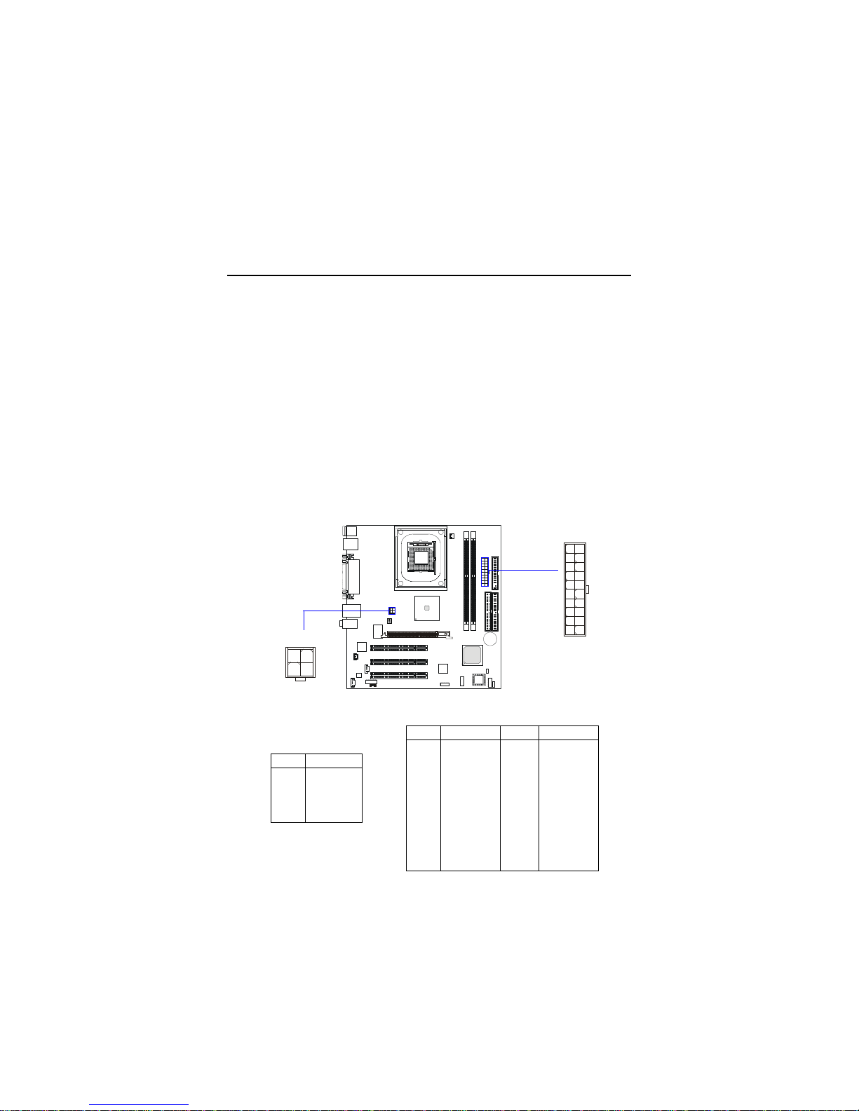
The mainboard supports ATX power supply for the power system. Before inserting the power supply connector, always make sure that all components are installed properly to ensure that no damage will be caused.
A TX 20-Pin Power Supply: CONN1
This connector allows you to connect to an ATX power supply. To
connect to the ATX power supply, make sure the plugs of the power supply is
inserted in the proper orientation and the pins are aligned. Then push down
the power supply firmly into the connector. The power connector supports
instant power on function which means that system will boot up immediately
when the power supply connector is inserted on the board.
A TX 12V Power Connector: JPW2
This 12V power connector is used to provide power to the CPU.
PIN SIGNAL
1 GND
2 GND
312V
412V
JPW2 Pin Definition
PIN SIGNAL
1 1 3.3V
12 -12V
13 GND
14 PS_ON
15 GND
16 GND
17 GND
18 -5V
19 5V
20 5V
PIN SIGNAL
1 3.3V
2 3.3V
3 GND
45V
5 GND
65V
7 GND
8 PW_OK
9 5V_SB
10 12V
CONN1 Pin Definition
CONN1
10
1
20
11
JPW2
1
2
3
4
Page 14
Hardware Setup
2-9
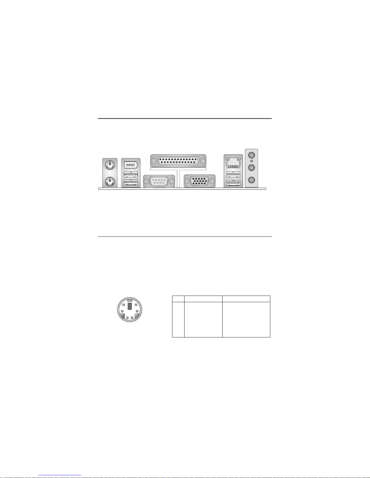
The Back Panel provides the following connectors:
Back Panel
Mouse/Keyboard Connector
The mainboard provides a standard PS/2® mouse/keyboard mini DIN
connector for attaching a PS/2® mouse/keyboard. Y ou can plug a PS/2® mouse/
keyboard directly into this connector. The connector location and pin assignments are as follows:
PS/2 Mouse/Keyboard
(6-pin Female)
2
1
3
4
5
6
Mouse
Keyboard USB
Parallel
COM A
L-Out
L-In
MIC
LAN
VGA USB
1394
PIN SIGNAL DESCRIPTION
1 Mouse/Keyboard Data Mouse/Keyboard data
2 NC No connection
3 GND Ground
4 VCC +5V
5 Mouse/Keyboard Clock Mouse/Keyboard clock
6 NC No connection
Pin Definition
Page 15
Chapter 2
2-10
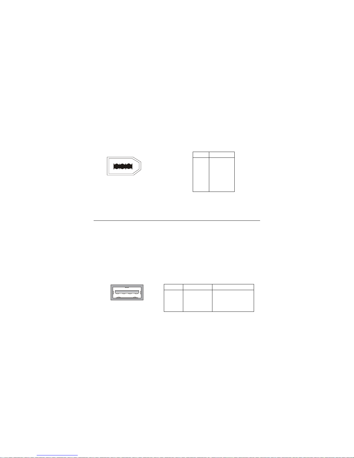
IEEE 1394 Port
The 6-pin IEEE 1394 port is used to connect 1394-compatible external
devices via 6-pin to 6-pin or 6-pin to 4-pin 1394 cables.
USB Ports
The back panel provides four UHCI (Universal Host Controller Interface)
USB (Universal Serial Bus) 2.0 ports for attaching USB devices such as keyboard,
mouse or other USB-compatible devices. You can plug USB devices directly
into the ports.
USB Port
1 2 3 4
PIN SIGNAL DESCRIPTION
1 VCC +5V
2 -Data 0 Negative Data Channel 0
3 +Data0 Positive Data Channel 0
4 GND Ground
Pin Definition
PIN SIGNAL
1 PWR
2 GND
3 TPB4 TPB+
5TPA6TPA+
Pin Definition
IEEE 1394 Port
12345
6
Page 16
Hardware Setup
2-11
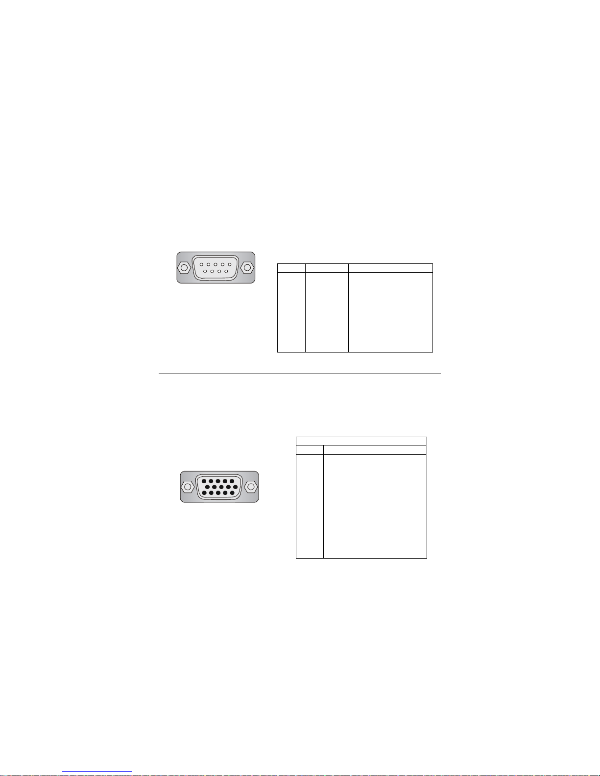
9-Pin Serial Port
1 2 3 4 5
6 7 8 9
Serial Port: COM A
The mainboard provides one 9-pin male DIN serial port COM A. Y ou can
attach a serial mouse or other serial devices to this port.
PIN SIGNAL DESCRIPTION
1 DCD Data Carry Detect
2 SIN Serial In or Receive Data
3 SOUT Serial Out or Transmit Data
4 DTR Data Terminal Ready
5 GND Ground
6 DSR Data Set Ready
7 RTS Request To Send
8 CTS Clear T o Send
9 RI Ring Indicate
Pin Definition
VGA DB 15 Pin Connector
One DB 15-pin VGA connector is provided for connection to a VGA
monitor.
Analog Video Display Connector (DB-15S)
PIN SIGNAL DESCRIPTION
1 Red
2 Green
3 Blue
4 Not used
5 Ground
6 Ground
7 Ground
8 Ground
9 Power
10 Ground
1 1 Not used
12 SDA
13 Horizontal Sync
14 Vertical Sync
15 SCL
Pin Definition
DB 15-Pin Female Connector
5 1
15 11
Page 17
Chapter 2
2-12
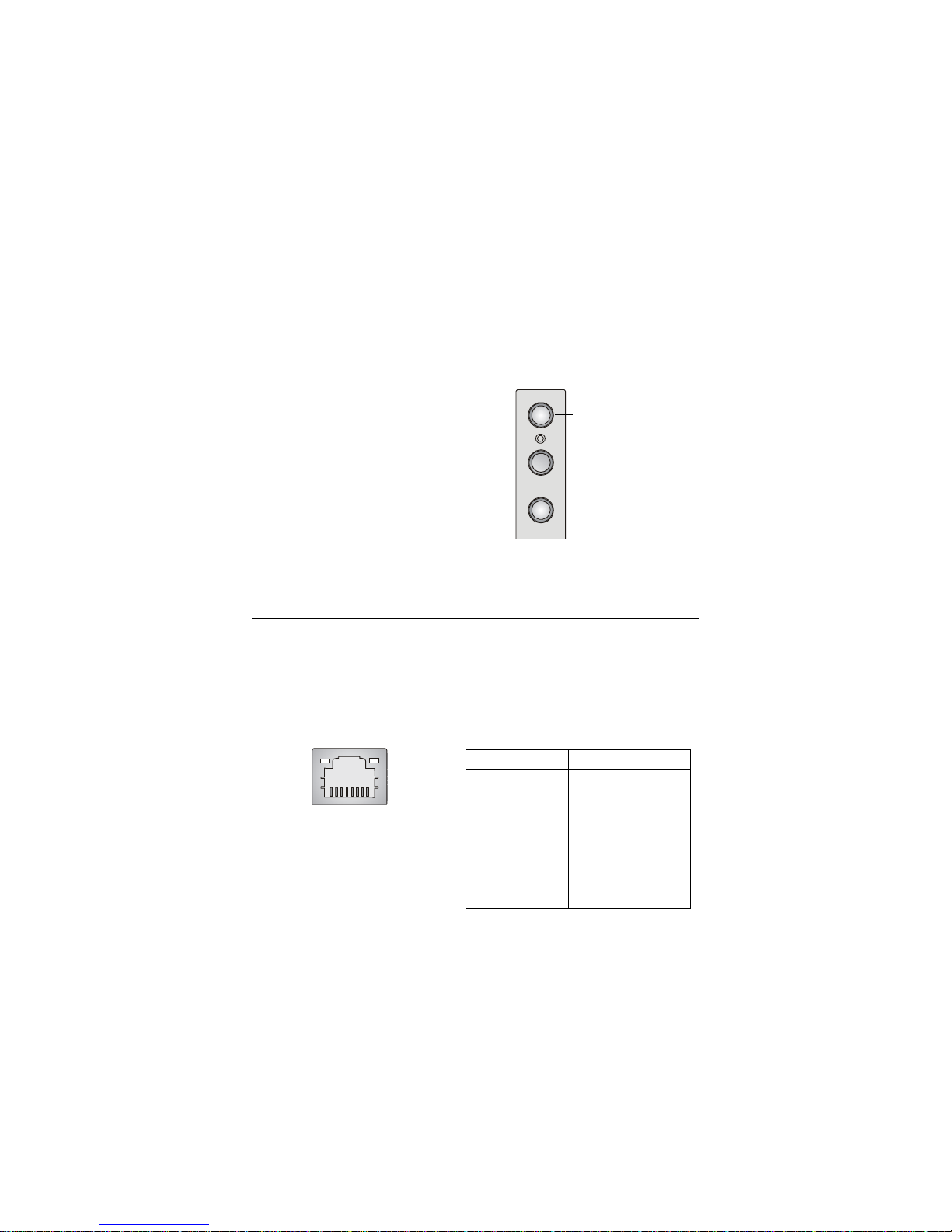
Audio Port Connectors
Line Out is a connector for Speakers or Headphones. Line In is used for
external CD player, Tape player, or other audio devices. Mic is a connector for
microphones.
1/8” Stereo Audio Connectors
RJ-45 LAN Jack
The mainboard provides one standard RJ-45 jack for connection to Local
Area Network (LAN). Y ou can connect a network cable to the LAN jack.
Pin Definition
PIN SIGNAL DESCRIPTION
1 TDP Transmit Differential Pair
2 TDN Transmit Differential Pair
3 RDP Receive Differential Pair
4 NC Not Used
5 NC Not Used
6 RDN Receive Differential Pair
7 NC Not Used
8 NC Not Used
Line Out
Line In
MIC
RJ-45 LAN Jack
8 1
Page 18
Hardware Setup
2-13
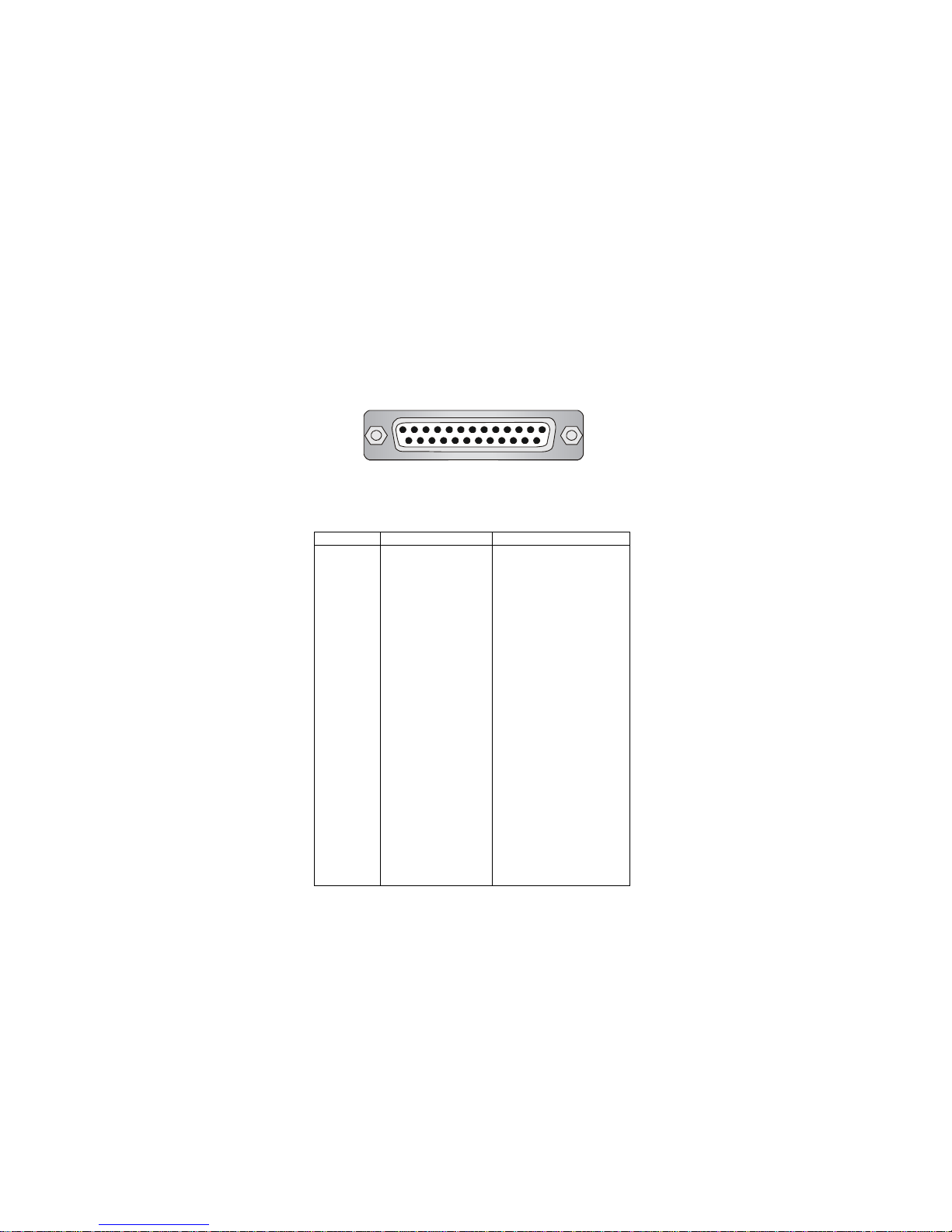
Parallel Port Connector: LPT1
The mainboard provides a 25-pin female centronic connector as LPT. A
parallel port is a standard printer port that supports Enhanced Parallel Port
(EPP) and Extended Capabilities Parallel Port (ECP) mode.
13 1
14
25
PIN SIGNAL DESCRIPTION
1 STROBE Strobe
2 DAT A0 Data0
3 DAT A1 Data1
4 DAT A2 Data2
5 DAT A3 Data3
6 DAT A4 Data4
7 DAT A5 Data5
8 DAT A6 Data6
9 DAT A7 Data7
10 ACK# Acknowledge
11 BUSY Busy
12 PE Paper End
13 SELECT Select
14 AUTO FEED# Automatic Feed
15 ERR# Error
16 INIT# Initialize Printer
17 SLIN# Select In
18 GND Ground
19 GND Ground
20 GND Ground
21 GND Ground
22 GND Ground
23 GND Ground
24 GND Ground
25 GND Ground
Pin Definition
Page 19
Chapter 2
2-14
The mainboard provides connectors to connect to FDD, IDE HDD, case,
modem, LAN, USB Ports, IR module and CPU/System F AN.
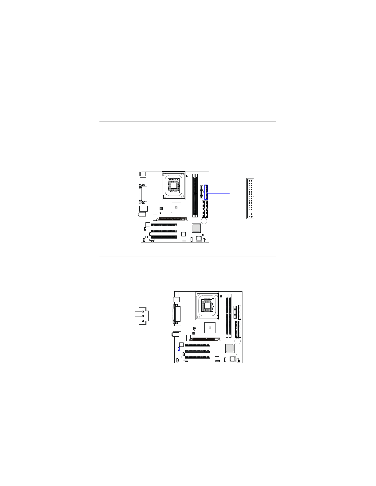
Floppy Disk Drive Connector: FDD1
The mainboard provides a standard floppy disk drive connector that
supports 360K, 720K, 1.2M, 1.44M and 2.88M floppy disk types.
Connectors
FDD1
Internal Speaker Connector: JSP1
This connector is used to connect the internal speaker if available.
JSP1
SPKR
GND
SPKL
Page 20
Hardware Setup
2-15
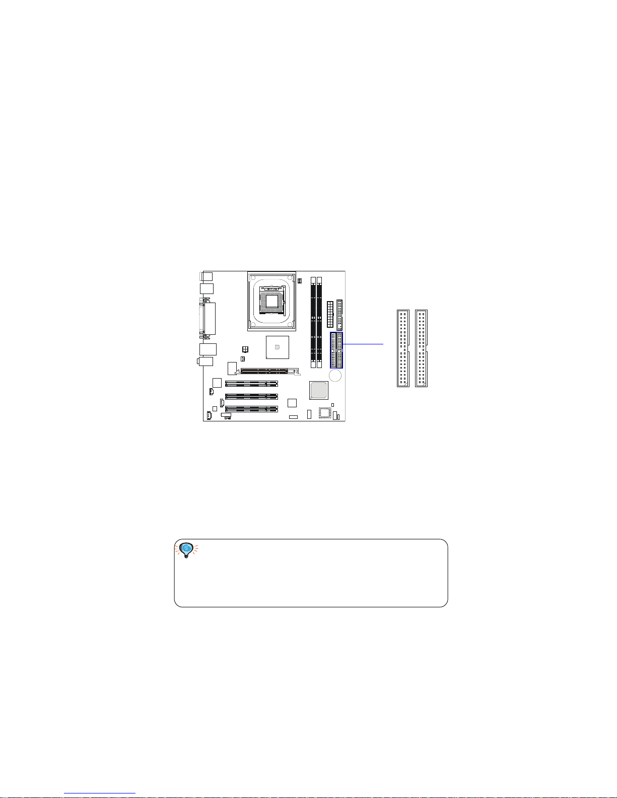
Hard Disk Connectors: PRIMAR1 & SECON1
The mainboard has a 32-bit Enhanced PCI IDE and Ultra DMA 33/66/100
controller that provides PIO mode 0~4, Bus Master, and Ultra DMA33/66/100
function. Y ou can connect up to four hard disk drives, CD-ROM, 120MB Floppy
(reserved for future BIOS) and other devices. These connectors support the
provided IDE hard disk cable.
PRIMAR1 (Primary IDE Connector)
The first hard drive should always be connected to IDE1. IDE1 can
connect a Master and a Slave drive. You must configure second hard
drive to Slave mode by setting the jumper accordingly.
SECON1 (Secondary IDE Connector)
IDE2 can also connect a Master and a Slave drive.
TIP:
If you install two hard disks on cable, you must configure the
second drive to Slave mode by setting its jumper. Refer to the
hard disk documentation supplied by hard disk vendors for jumper
setting instructions.
PRIMAR1
SECON1
Page 21
Chapter 2
2-16
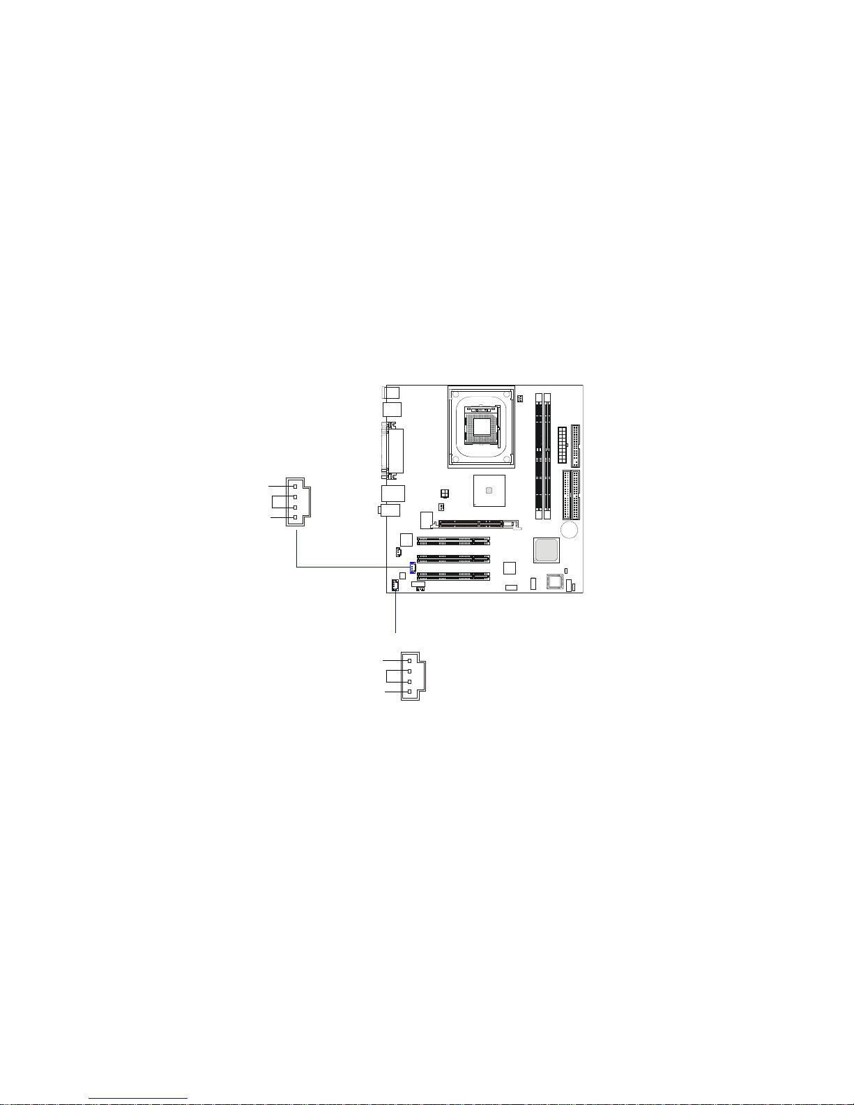
CD-In Connector: JCD1
The connector is for CD-ROM audio connector.
Aux Line-In Connector: JAUX1
The connector is for DVD add-on card with Line-in connector.
JCD1
GND
R
L
JAUX1
GND
R
L
Page 22
Hardware Setup
2-17
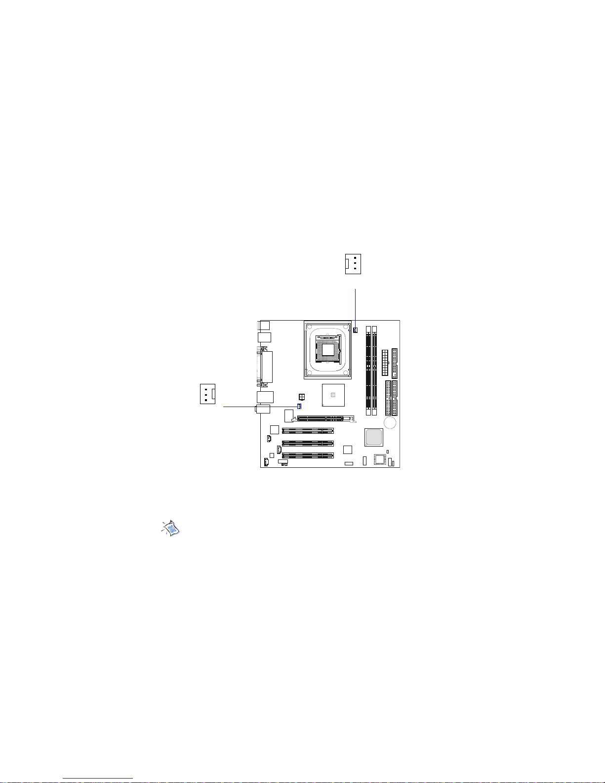
Fan Power Connectors: C_F AN1/S_F AN1
The C_FAN1 (processor fan) & S_FAN1 (system fan) support system
cooling fan with +12V. It supports three-pin head connector. When connecting the wire to the connectors, always take note that the red wire is the positive
and should be connected to the +12V, the black wire is Ground and should be
connected to GND.
S_FAN1
SENSOR
+12V
GND
C_FAN1
SENSOR
+12V
GND
Note: Always consult the vendor for proper CPU cooling fan.
Page 23
Chapter 2
2-18
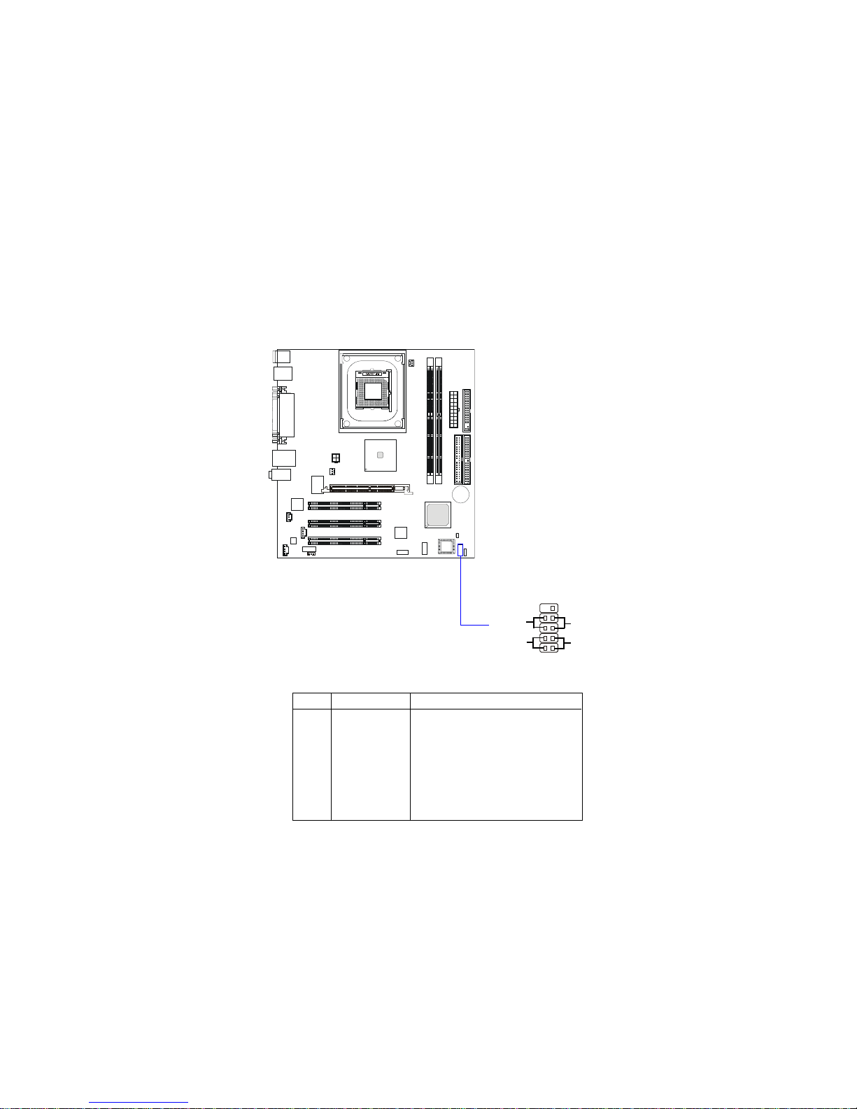
Front Panel Connector: JFP1
The mainboard provides one front panel connector for electrical connection to the front panel switches and LEDs. The JFP1 is compliant with Intel
®
Front Panel I/O Connectivity Design Guide.
PIN SIGNAL DESCRIPTION
1 HD_LED_P Hard disk LED pull-up
2 FP PWR/SLP MSG LED pull-up
3 HD_LED_N Hard disk active LED
4 FP PWR/SLP MSG LED pull-up
5 RST_SW_N Reset Switch low reference pull-down to GND
6 PWR_SW_P Power Switch high reference pull-up
7 RST_SW_P Reset Switch high reference pull-up
8 PWR_SW_N Power Switch low reference pull-down to GND
9 NC No connection
Pin Definition
12
910
JFP1
HDD
LED
Reset
Switch
Power
LED
Power
Switch
+
Page 24
Hardware Setup
2-19
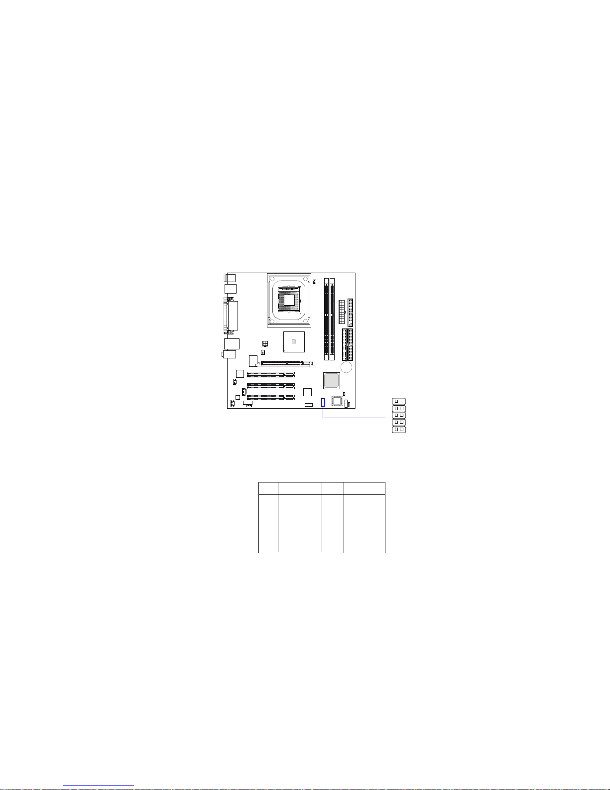
Front USB Connector: JUSB1
The mainboard provides one USB 2.0 pinheader for connection to USB
devices. USB 2.0 technology increases data transfer rate up to a maximum
throughput of 480Mbps, which is 40 times faster than USB 1.1, and is ideal for
connecting high-speed USB interface peripherals such as USB HDD, digital
cameras, MP3 players, printers, modems and the like.
Pin Description Pin Description
1 VCC 2 VCC
3 USB P4- 4 USB P55 USB P4+ 6 USB P5+
7 GND 8 GND
9 KEY 10 NC
Pin Definition
JUSB1
1
9
2
10
Page 25
Chapter 2
2-20
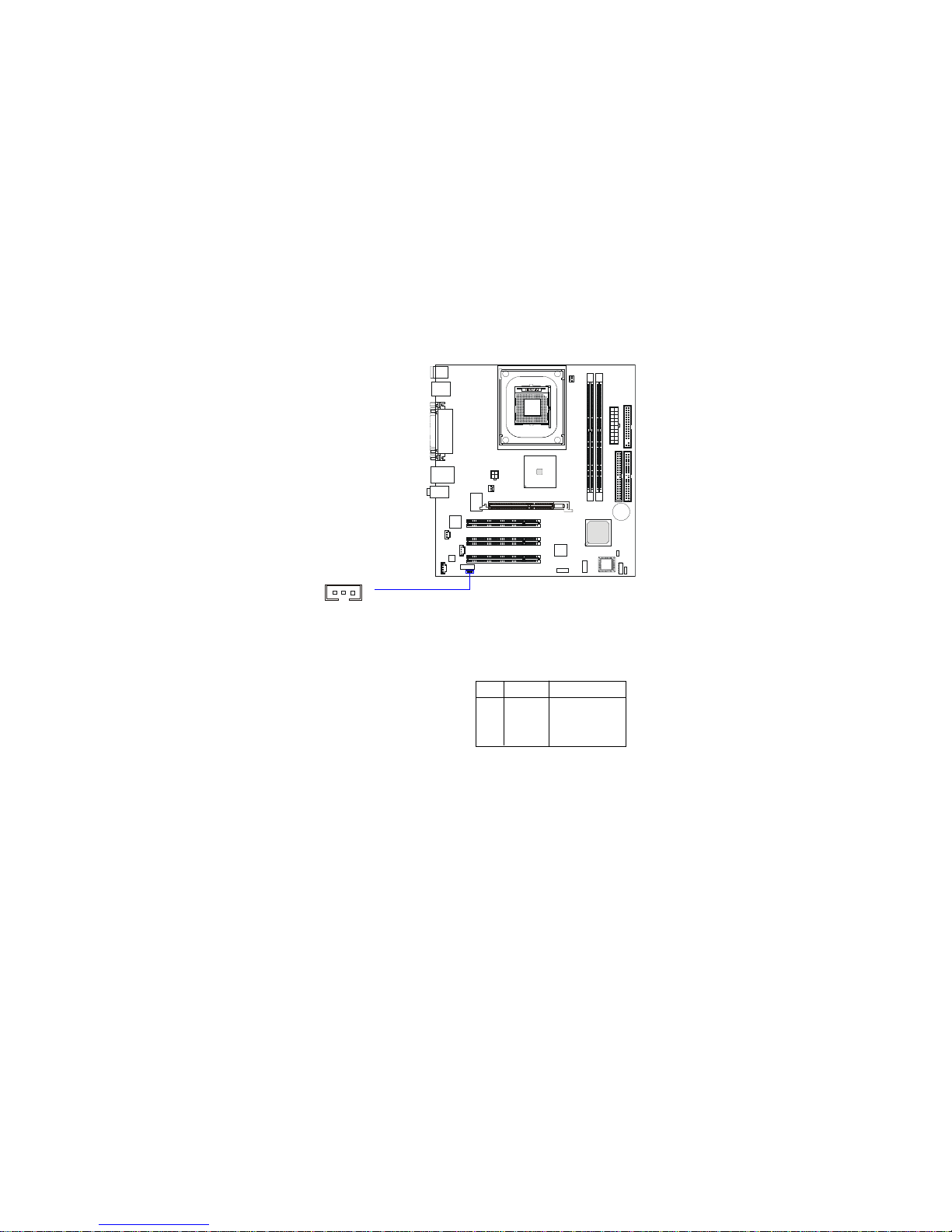
Front Microphone Connector: JFMIC
This connector is used to connect the front panel microphone if available.
1 3
JFMIC
Pin Definition
PIN SIGNAL DESCRIPTION
1 FMIC Front Microphone
2 GND Ground
3 VCC VCC5V
Page 26
Hardware Setup
2-21
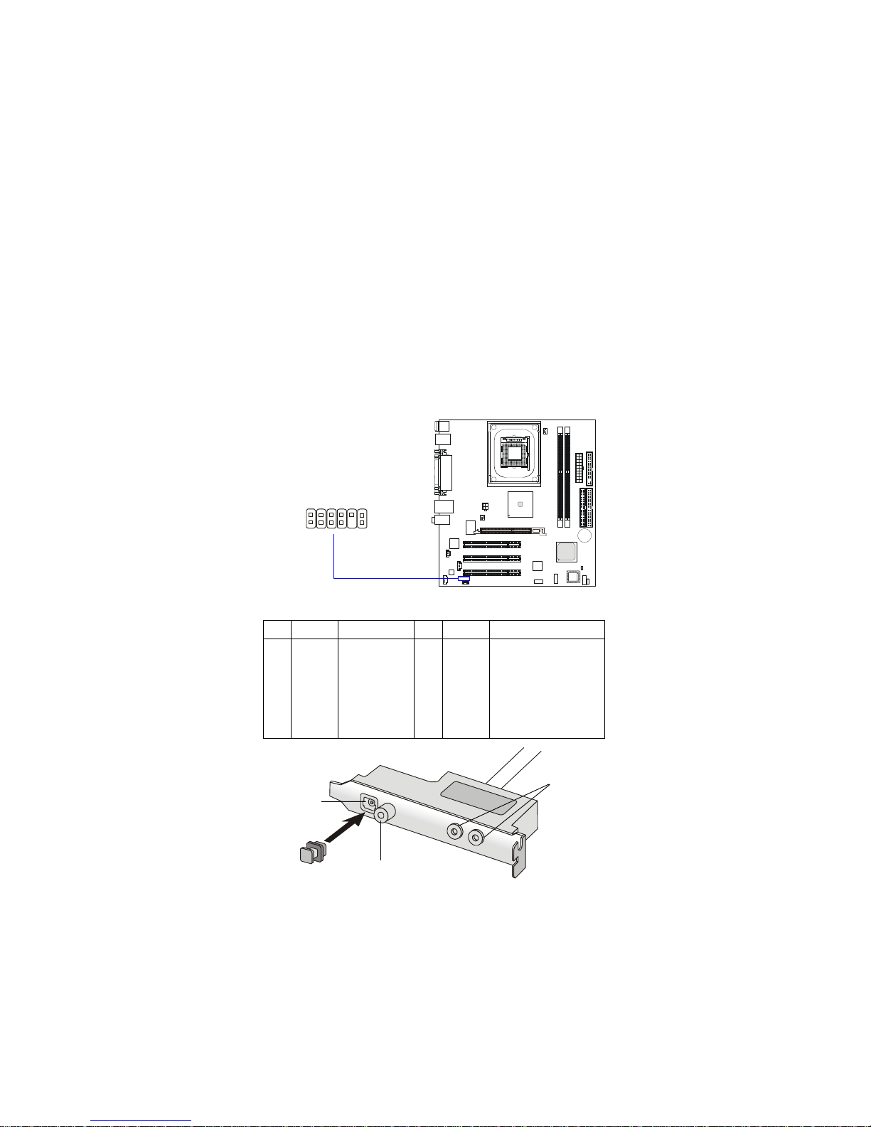
S-Bracket Connector: JSPD2
This connector allows you to connect the optional S-Bracket for Sony &
Philips Digital Interface (SPDIF). The S-Bracket offers 2 SPDIF jacks for digital
audio transmission (one for optical fiber connection and the other for coaxial),
and 2 analog Line-Out jacks for 4-channel audio output.
T o attach the fiber-optic cable to optical SPDIF jack, you need to remove
the plug from the jack first. The two SPDIF jacks support SPDIF output only.
For more information on the S-Bracket, refer to Appendix. Using 4- or 6-Chan-
nel Audio Function.
S-Bracket (optional)
SPDIF jack (optical)
SPDIF jack (coaxial)
Analog Line-Out
jacks
Plug
PIN SIGNAL DESCRIPTION PIN SIGNAL DESCRIPTION
1 VCC5 VCC 5V 2 VDD3 VDD 3.3V
3 SPDFO S/PDIF output 4 (No Pin) Key
5 GND Ground 6 SPDFI S/PDIF input
7 LFE-OUT Audio bass output 8 SOUT-R Audio right surrounding output
9 CET-OUT Audio center output 1 0 SOUT-L Audio left surrounding output
11 GND Ground 12 GND Ground
Pin Definition
CEN/SUB
RL/RR
JSPD2
1 11
2 12
Page 27
Chapter 2
2-22
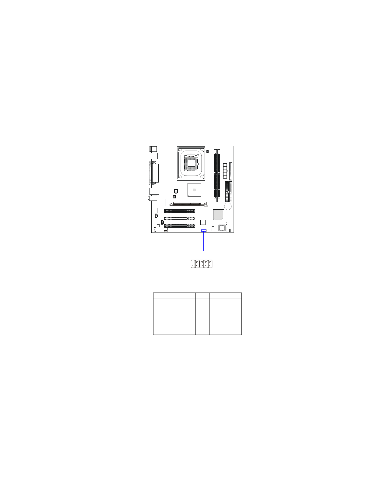
IEEE 1394 Connector: J1394_2
The mainboard provides one 1394 pinheader that allows you to connect
additional IEEE 1394 devices.
J1394_2
1 9
2
10
PIN SIGNAL PIN SIGNAL
1TPA+ 2 TPA3 Ground 4 Ground
5 TPB+ 6 TPB7 Cable power 8 Cable power
9 Key (no pin) 10 Ground
Pin Definition
Page 28
Hardware Setup
2-23
Jumpers
The motherboard provides one jumper for you to set the computer’s
function. This section will explain how to change your motherboard’s function
through the use of the jumper.
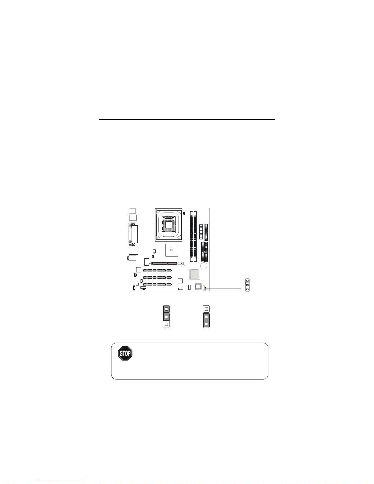
Clear CMOS Jumper: JBA T1
There is a CMOS RAM on board that has a power supply from external
battery to keep the data of system configuration. With the CMOS RAM, the
system can automatically boot OS every time it is turned on. That battery has
long life time for at least 5 years. If you want to clear the system configuration,
use the JBAT1 (Clear CMOS Jumper ) to clear data. Follow the instructions
below to clear the data:
JBAT1
1
Keep CMOS Clear CMOS
3
1
3
1
To clear CMOS, first make the #2-3 pin short connected after the system is off. And then power on the
system and short connect #1-2 pin before entering the
BIOS (Standard CMOS Features) to clear data.
WARNING!
Page 29
Chapter 2
2-24
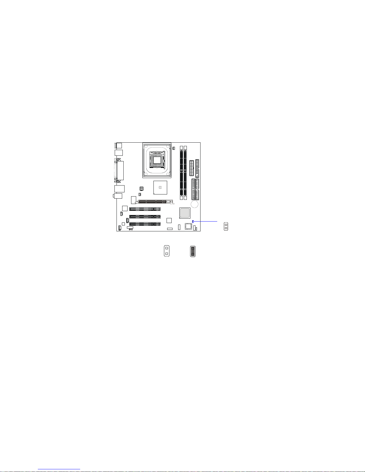
Clear BIOS Password Jumper: JPWD1
The jumper is used to clear the BIOS password. T o clear the password,
open the jumper and restart your computer.
Normal
Clear
JPWD1
Page 30
Hardware Setup
2-25
Slots
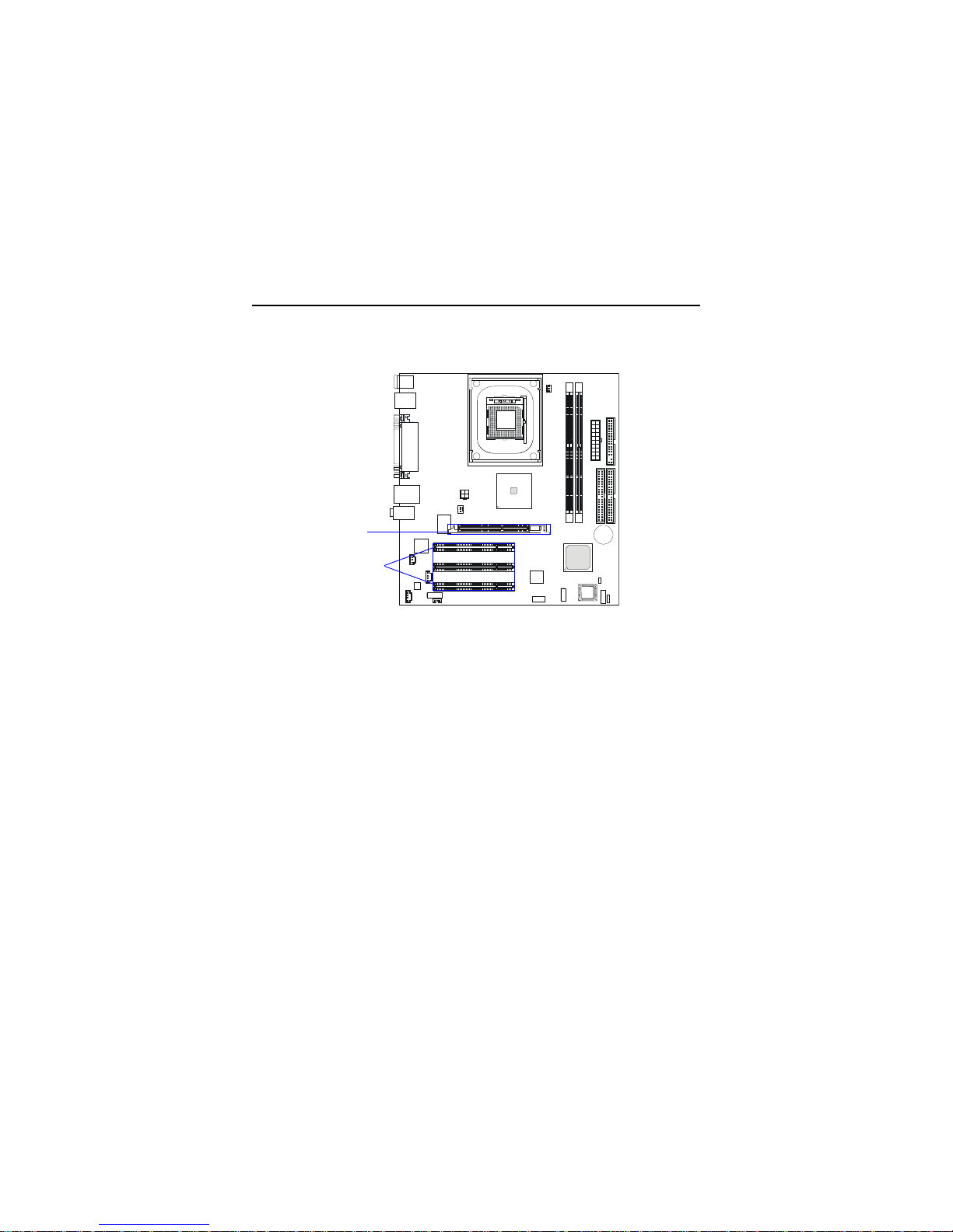
AGP (Accelerated Graphics Port) Slot
The AGP slot allows you to insert the AGP graphics card. AGP is an
interface specification designed for the throughput demands of 3D graphics.
It introduces a 66MHz, 32-bit channel for the graphics controller to directly
access main memory and provides three levels of throughputs: 1x (266Mbps),
2x (533Mbps) and 4x (1.07Gbps). Please especially note that, for enhanced 3D
visualization, Intel® 845 chipset supports the latest graphics devices through
1.5V AGP 4X interface. No 3.3V AGP 2X interface is supported. Installing
3.3V AGP 2X cards on Intel® 845 based mainboards will damage the mainboards.
PCI (Peripheral Component Interconnect) Slots
The PCI slots allow you to insert the expansion cards to meet your needs.
When adding or removing expansion cards, make sure that you unplug the
power supply first. Meanwhile, read the documentation for the expansion card
to make any necessary hardware or software settings for the expansion card,
such as jumpers, switches or BIOS configuration.
The motherboard provides three 32-bit Master PCI bus slots and one
AGP slot.
PCI Slots
AGP Slot
Page 31
Chapter 2
2-26
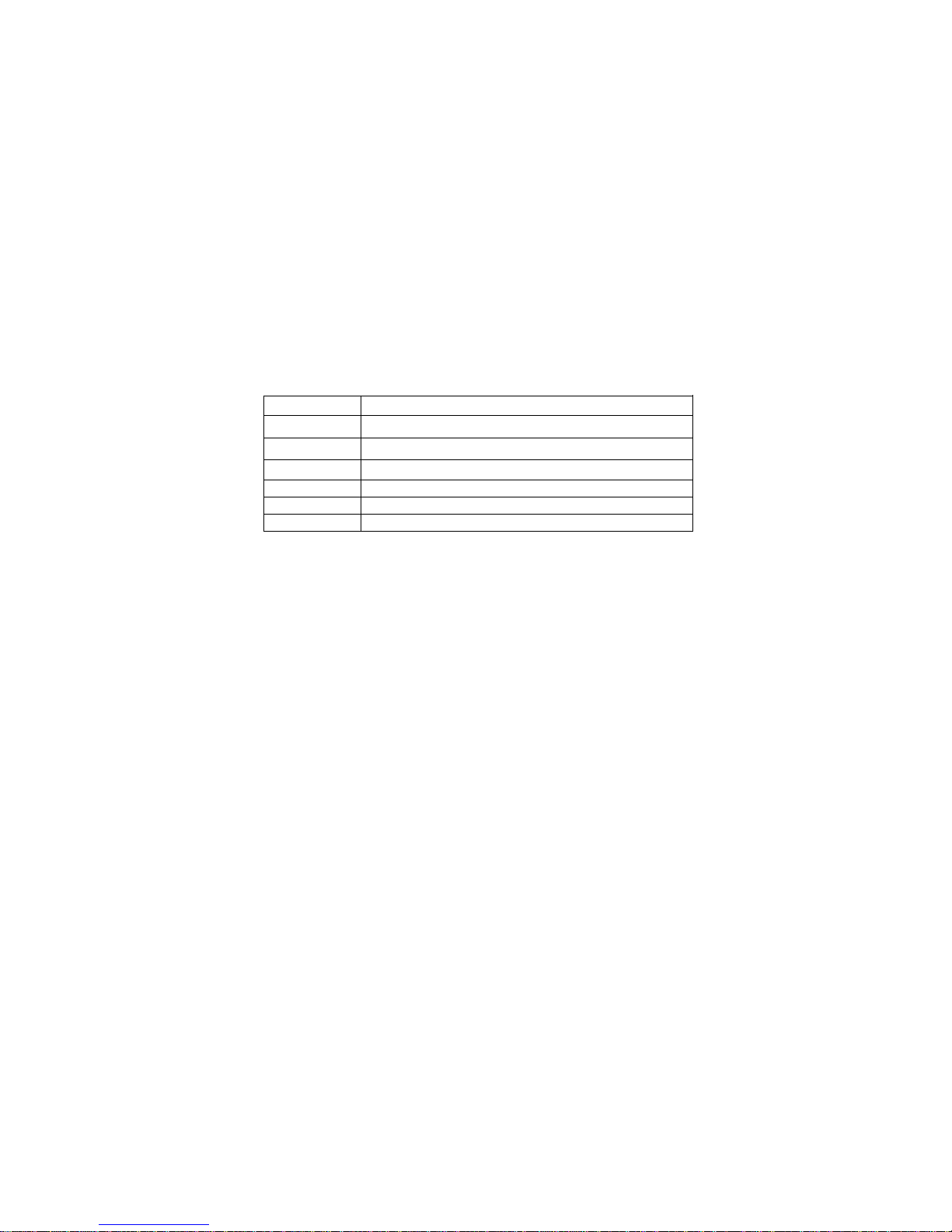
PCI Interrupt Request Routing
The IRQ, acronym of interrupt request line and pronounced I-R-Q, are
hardware lines over which devices can send interrupt signals to the
microprocessor. The PCI IRQ pins are typically connected to the PCI bus INT
A# ~ INT H# pins as follows:
Order 1 Order 2 Order 3 Order 4
PCI Slot 1 INT F# INT G# INT H# INT E#
PCI Slot 2 INT G# INT H# INT E# INT F#
PCI Slot 3 INT D# INT A# INT B# INT C#
LAN Controller INT H# INT E#
AGP Slot INT A# INT B#
1394 Controller INT H#
 Loading...