


Version 1.0
PENTIUM is a trademark of the Intel Corporation.
PS/2 is a trademark of the IBM Corporation.
1

Mainboard Name: MS-6104
Manual Rev: 1.0
BIOS Version: W48X
Release Date: June, 1996
FCC-B Radio Frequency Interference Statement
This equipment has been tested and found to comply with the limits for a
class B digital device, pursuant to part 15 of the FCC rules. These limits are
designed to provide reasonable protection against harmful interference
when the equipment is operated in a commercial environment. This
equipment generates, uses and can radiate radio frequency energy and, if
not installed and used in accordance with the instruction manual, may cause
harmful interference to radio communications. Operation of this equipment
in a residential area is likely to cause harmful interference, in which case
the user will be required to correct the interference at his own expense.
Notice 1
The changes or modifications not expressly approved by the party
responsible for compliance could void the user's authority to operate the
equipment.
Notice 2
Shielded interface cables and A.C. power cord, if any, must be used in
order to comply with the emission limits.
VOIR LA NOTICE D'INSTALLATION AVANT DE RACCORDER
AU RESEAU.
2

Edition
June 1996
Copyright Notice
This manual is copyrighted. No guarantee is given as to the
correctness of its contents. We reserve the right to make changes
without notification.
Trademarks
All trademarks used in this manual are the property of their respective
owners.
3

Table of Contents
Chapter 1: Introduction
System Board Specifications ---------------------------------------- 1-1
System Board Layout ------------------------------------------------ 1-4
Chapter 2: Hardware Installation
System Clock Selection: JC1--------------------- ------------------ 2-2
Flash ROM Selection: JP3------------------------------------------- 2-3
Power Saving Switch Connector: JG1----------------------------- 2-3
CMOS RAM Clear: JP7---------------------------------------------- 2-4
System Memory Installation: SIMM4 -SIMM1 ------------------- 2-4
DRAM Installation----------------------------------------------------
CPU Installation & Fan Power Connector : -----------------------
2-6
2-7
Case Block Connector: JFP------------------------------------------ 2-8
Power Supply Connector--------------------------------------------- 2-9
Keyboard Connector: PS/2-KB or JMS1--------------------------
Mouse Connector: JMS or PS/2 Style Mouse---------------------
2-
1
0
2-10
Serial Port Connectors: COM1 & COM2-------------------------- 2-11
Parallel Port Connectors: PRN--------------------------------------- 2-11
4

Floppy Disk Connector : Floppy ------------------------------------ 2-12
Hard Disk Connector: IDE1 , IDE2----------------------------- 2-12
IrDA Infrared Module Connector: IRCON--------------------- 2-14
USB Connector : USB (USB1,USB2) --------------------------- 2-15
Chapter 3: AWARD BIOS SETUP (Version 4.51)
Entering Setup------------------------------------------------------- 3-1
Getting Help--------------------------------------------------------- 3-2
The Main Menu----------------------------------------------------- 3-3
Standard CMOS Setup ------------------------------------------- 3-6
BIOS Features Setup ---------------------------------------------- 3-9
Chipset Features Setup -------------------------------------------- 3-16
Power Management Setup----------------------------------------- 3-22
PNP/PCI Configuration Setup ------------------------------------ 3-29
Load BIOS/ Setup Defaults --------------------------------------- 3-32
Integrated Peripherals---------------------------------------------- 3-33
Supervisor/User Password Setting-------------------------------- 3-39
IDE HDD Auto Detection---------------------------------------- 3-40
5

CHAPTER 1 INTRODUCTION
Chapter 1
INTRODUCTION
The PCI P6 NA2 PCI/ISA system board is an ATX high-performance
personal computer system board based on the Pentium ä Pro
microprocessor.
System Board Specifications
Power Selection:
· ATX or PS/2 Power Selection
Hardware Installation:
· The system board provides “Plug & Play” BIOS which detects
the peripheral devices and expansion cards of the board
automatically.
· The system board provides a Desktop Management Interface
(DMI) function which records your sytem board
specifications.
CPU:
· The system board supports 150/166/180/200 MHz Intel Pentium
Pro CPUs.
Cache Memory:
· Internal Level 1 Cache: 8KB instruction code and 8KB data
cache.
· Internal Level 2 Cache: 256KB/512KB(depending on CPU)
1 -
1

CHAPTER 1 INTRODUCTION
Chip Set:
· The system board utilizes the Intel Pentium Pro Chipset which
includes SB82441FX (PMC) PCI bridge and memory controller, and
SB82442FX(DBX) Data Bus Accelerator and SB82371(P11X3) PCI
to ISA Bridge.
Multi-I/O:
· The system board has a built in Plug and Play Winbond W83877
and Multi-I/O chipsets to support 2 high-speed serial ports, one
parallel port with ECP and EPP capabilities, and one floppy
drive.
Enhanced IDE Support:
· A PCI IDE controller and built-in P11X3 supports dual channels
and four hard drives.
IrDA and PS/2 support:
· This board supports an infrared port connector for wireless
interface and a jumperless PS/2 mouse connector.
USB support:
· The system board supports a two channel USB port connector.
AHA SCSI BIOS:
· This optional feature supports on-board an AHA AIC 7880 SCSI
controller.
Main Memory:
· Supports four memory banks using four 72-pin SIMM sockets.
· Up to 512 Mbytes main memory.
· Supports Fast Page (FP) Mode, Extended Data Output (EDO)
Mode, and Burst Extended Data Output (BEDO) Mode
DRAM.
1 -
2

CHAPTER 1 INTRODUCTION
· Supports symmetric or asymmetric DRAM memory, 70ns or
faster.
· Provides ECC (Error Check Function) Function.
Slots:
· Four 32-bit PCI Bus slots and four 16-bit ISA bus slots. One
shared slot that can be used as ISA or PCI.
On-Board I/O:
· A 32-bit enhanced dual channel and 4 enhanced hard drives PCI IDE
controller, supports fast-ATA2 PIO Mode 0-4 and bus Master
DMA Mode 2.
· One floppy disk drive controllers, two high-speed serial prots,
and one parrallel port with ECP or EPP capabilities.
· IrDA function.
· Optional SCSI controller.
· 2 channel USB function.
Keyboard Connector:
· PS/2 keyboard interface and PS/2 Mouse interface.
· 5X2-pin connector for PS/2 Keyboard and Mouse.
Dimensions
· ATX size: 30cm x 24.5cm x 6-layer PCB.
Mounting
· 9 mounting holes
1 -
3

CHAPTER 1 INTRODUCTION
1.2 System Board Layout
Figure 1-1
1 -
4

CHAPTER 2 HARDWARE INSTALLATION
Chapter 2
HARDWARE INSTALLATION
It is important to set jumpers correctly. Improper jumper setting
will cause system instability, destruction of components, and/or
system hang-up.
Step 1: Set the CPU BUS CLOCK and Core Frequency Ratio
(see “JC1 Jumper” section)
JC1 is used for CPU BUS CLOCK and bus to core
frequency ratio. Caution: If these jumpers aren’t set
correctly, it will cause the system to be unstable or system
hang-up, and it may reduce the life cycle of the CPU.
Step 2: Install CPU, VRM, DRAM, Expansion Card, and External
cables (see “Connectors” section)
Caution: All parts need to be set to avoid system board
malfunction.
Step 3: Turn Power on and setup BIOS software (see “BIOS Setup”
section)
2 -
1

CHAPTER 2 HARDWARE INSTALLATION
Jumper Settings
This table is useful to conveniently locate information on specific
jumpers and connectors.
Jumper Setting/Description Page
JC1 CPU Frequency Selection 2-2
JP3 Flash ROM Selection 2-3
JG1 Power Saving Switch Connector 2-3
JP1 CMOS RAM Clear 2-4
JFP Case Connector Block 2-7
PS/2-KB Keyboard Connector 2-9
PS/2-MS PSII Mouse Connector 2-9
COM1 & COM2 Serial Port Connector 2-10
PRN Parallel Port Connector 2-10
FDD Floppy Disk Connector 2-11
IDE1 & IDE2 Hard Disk Connector 2-11
JFAN CPU Fan Connector 2-12
IRCON Infrared Module 2-12
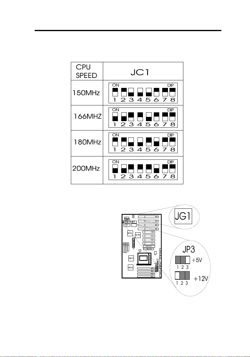
CPU Frequency Selection: JC1
The CPU BUS CLOCK of the MS-6104 supports two frequencies:
60MHz (default) and 66MHz. Refer to the following figure for
jumper location and settings.
2 -
2
CHAPTER 2 HARDWARE INSTALLATION
JC1 SETTINGS
Flash ROM Selection: JP3
Jumper JP3 sets the mainboard to be used with either +12V or +5V
Flash ROM.
2 -
3
CHAPTER 2 HARDWARE INSTALLATION
Power Saving Switch: JG1
Attaching a power saving switch to this connector will allow the
system into sleep mode whenever this switch is pressed.
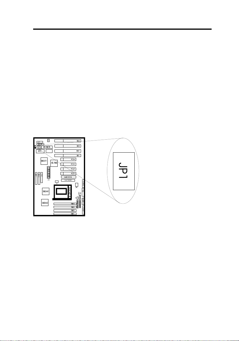
CMOS RAM Clear: JP1
The system board configuration is stored in CMOS RAM. If you
need to clear the system board configuration do the following:
1. Turn power off.
2. Short jumper JP1.
3. Turn power on.
4. Enter the BIOS setup
to re-setup the BIOS.
5. Reboot the system.
2 -
4

CHAPTER 2 HARDWARE INSTALLATION
Note: Some CMOS RAMs require a different procedure:
1. Short jumper JP1.
2. Turn on system
3. Turn off the system
4. Remove JP1 jumper.
5. Turn on power again.
6. Reset BIOS.
System Memory Installation: SIMM1-SIMM4
The system board provides four 72-pin SIMM sockets which are
numbered from SIMM1 to SIMM4. The system board supports
memory sizes from 8MB to 512MB using 4MB, 8MB, 16MB,
32MB, 64MB, and 128MB DRAM modules. It supports both Fast
Page Mode (FP), Extended Data Output Mode (EDO), and Burst
Extended Data Output Mode (BEDO), with symmetric or
asymmetric row/colum address.
DRAM Population Rules
In order to create a memory array, certain rules must be followed.
The following set of rules allows for optimum configuration.
1. DRAM modules must be populated in pairs; the
memory array is 64-or-72-bits wide. (64-bit
modules are no parity.)
2 -
5

CHAPTER 2 HARDWARE INSTALLATION
2. DRAM modules can be populated in any order
(i.e. SIMM1/2 does not have to be populated
before SIMM3/4 are used.)
3. DRAM module pairs need to be populated with
the same densities...single or double. For
example, SIMM1/2 sockets must be populated
with identical densities. However SIMM3/4
sockets can be populated with different densities
than SIMM socket pair 1/2. In addition,
asymetric DRAMs of the same type should be
used in a whole row.
4. BEDO, EDO, FP modes can be mixed in the
memory array. However only one type should be
used per SIMM socket pair. For example:
SIMM sockets 1 & 2 can be populated with EDO
while SIMM sockets 3 & 4 can be populated with
FP mode type DRAM.
5. The DRAM timing which provides the DRAM
speed grade control for the entire memory array
must be programmed to use the timing of the
slowest DRAM that is currently installed.
Note: To use the ECC (Error Code Correct) function, a SIMM module with
parity support must be used. At this time you can turn on the ECC function
in the BIOS setup.
Note: Before using DRAM modules, make sure that that the modules used
is the same as in the above chart.
DRAM Memory Installation
2 -
6

CHAPTER 2 HARDWARE INSTALLATION
1. Check to see which side of the plastic safety tab is on the slot
before installing.
2. Line up the notch of the module against the slot.
3. Press the module firmly into place at a 45 degree angle.
4. Carefully press down on the top edge of the module to set it in
the SIMM slot.
5. The plastic guides should go through the two holes on the sides
and the metal clips should snap on the other side. If it doesn’t
slide in easily, take it out and try again.
6. To release module, squeeze both metal clips outwards and rock
the module out of the metal clips.
CPU Installation
Open Socket 8 by pulling the lever away from the socket then
upwards at a 90 degree right angle. Insert the CPU according to the
orientation as shown. IF it does not fall in easily then try a different
direction because the pin configuration only fits one way as opposed
to earlier CPUs. Make sure that the CPU is well seated and close to
the lever. See following figure:
2 -
7

CHAPTER 2 HARDWARE INSTALLATION
Case Block Connector : JFP
The Turbo LED, Hardware Reset, Key lock, Power LED, Power
Saving LED, Speaker,and HDD LED all connect to the JFP
connector block as below.
2 -
8

CHAPTER 2 HARDWARE INSTALLATION
Note : The hardware Turbo switch is not functional. But the Turbo
LED can be controled by software Turbo/Deturbo.
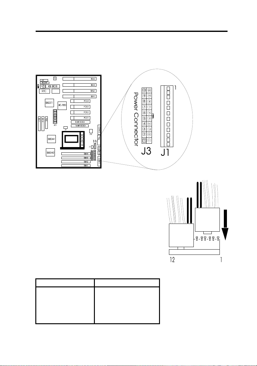
Power Supply Connector
The power supply connector is a twelve-pin male connector (J1) or a
2X10-pin ATX connector (J3). Dual connectors from the power
supply can fit in only one direction. Make sure to attach the
2 -
9
CHAPTER 2 HARDWARE INSTALLATION
connector with the two black wires at the center as shown in the
diagram below.
12-pin Connector Pin Description
Pin Description Pin Description
1 Power Good
2 +5V DC
3 +12V DC
4 -12V DC
5 Ground
7 Ground
8 Ground
9 -5V DC
10 +5V DC
11 +5V DC
2 -
10

CHAPTER 2 HARDWARE INSTALLATION
6 Ground 12 +5V DC
2X10-Pin Connector Pin Description
Pin Description Pin Description
1 3.3V 11 3.3V
2 3.3V 12 -12V
3 GROUND 13 GROUND
4 5V 14 PS-ON
5 GROUND 15 GROUND
6 5V 16 GROUND
7 GROUND 17 GROUND
8 PW-OK 18 -5V
9 5VSV 19 5V
10 12V 20 5V
Keyboard Connector: PS/2-KB, or JMS1
Choose either PS/2-KB or JMS1 as a keyboard connector. The
system board provides a standard five-pin female DIN connector for
attaching a keyboard. You can plug a keyboard cable directly into
this connector.
2 -
11

CHAPTER 2 HARDWARE INSTALLATION
Mouse Connector: JMS or PS/2 Style Mouse
Choose either PS/2 or JMS as a mouse connector.
Serial Port Connectors: COM1 & COM2
The system board has two 9-pin male serial port connectors, COM1
and COM2. The two ports are 16550 high speed communication
ports that send/receive
16 byte FIFOs. You
can attach a mouse or
a modem cable
directly to these
connectors. COM1
and COM2 converter
plugs are provided
with the system board.
Parallel Port Connectors: PRN
The system board provides a 25-pin female parallel port connector,
PRN. The parallel port is a standard printer port that also supports
Enhanced Parallel Port (EPP) and Extended Parallel Port (ECP).
See following figure:
2 -
12

CHAPTER 2 HARDWARE INSTALLATION
Floppy Disk Connector: Floppy
The system board also provides a standard floppy disk connector,
FDD, that supports 360K, 720K, 1.2M, or 1.44M floppy disk types.
You can attach a
floppy disk cable
directly to this
connector.
Hard Disk Connector: IDE1, IDE2
2 -
13
CHAPTER 2 HARDWARE INSTALLATION
The system board has a 32-bit Enhanced PCI IDE Controller that
provides for two HDD connectors, IDE1 (primary) and IDE2
(secondary). You can connect up to four hard disk drives or devices
to IDE1 and IDE2.
IDE1 (Pimary IDE Connector)
If you only use one hard disk you must connect to IDE1. You can
also connect two hard disks, a Master drive and a Slave drive to
IDE1.
IDE2 (Secondary IDE Connector)(see preceding figure)
If you use two hard disks, you can connect one to HDD1 and the
other to HDD2. However, you must use a driver program for the
hard disk connected to IDE2. You can also connect two hard disks
to HDD2, a Master drive and a Slave drive.
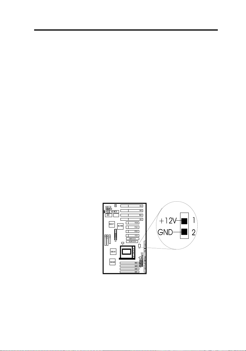
CPU Fan Connector: JFAN
This 2-pin connector connects a power source of +12V with your
CPU’s cooling fan. Check the voltage range and polarity of your
cooling fan before you connect it.
2 -
14

CHAPTER 2 HARDWARE INSTALLATION
IrDA Infrared Module Connector: IRCON
The system board provides a 5-pin infrared connector-JP4 as an
optional module for wireless transmittng and receiving.
Infrared ( IrDA/Consumer IR) Connector
Serial Port 2 can be configured to support an IrDA module via
a 5-pin header connector. The IrDA functions enables the user
to transfer files to or from portable devices such as laptops,
PDAs, and printers, using application software such as Lap
Link. The IrDA provides data transfers at 115kbps from a
distance of 1 meter.
PS/2 Style Switch with Voltage Connector: J2
When using a PS/2 style switch with a standby +5V cable power
switch, connect the +5V cable to J2.
2 -
15

CHAPTER 2 HARDWARE INSTALLATION
Remote On/Off: J10
The 2-pin connector must utilize a toggle switch (one push
on/second push off). To use this function an ATX or PS/2 with a
stand by +5V cable switch power is needed.
Remote ON/OFF and Soft Power Support
When connected to a momentary SPST switch, this 2-pin header is
used to power up the system. When used with a power supply that
supports remote power on/off the system board can be turned off by
three different methods: The front panel “Remote On/Off” switch, a
thermal trip signal from the Pentuim PROÔ, or a soft signal from
the Super I/O controller.
In “Soft Off,” an APM command isssued to the system BIOS will
cause the power supply to turn off via the “PS ON”” control signal
on the power connector. For example WindowÔ 95 will issue this
APM command when the user clicks on the Shutdown icon. Power
can be restored via a front panel power button connected to the front
panel header.
USB Connector : USB
This 10-pin connector connects USB cable to support USB device.
2 -
16

CHAPTER 2 HARDWARE INSTALLATION
SCSI Hard Disk Connector: J4 & J6 (optional)
J4 is a 68-pin 16-bit SCSI Hard Disk Connector. J6 is a 50-pin 8bit SCSI Hard Disk Connector. The SCSI controller interupt signal
is shared with the PCI 4 slot. If you wish to install a PCI card in the
PC1 4 slot, you must install the SCSI driver before installing any
other drivers.
2 -
17

Chapter 3 AWARD BIOS USER’S GUIDE
Chapter 3
AWARD BIOS SETUP (Version 4.51)
Award's BIOS ROM has a built-in Setup program that allows users
to modify the basic system configuration. This type of information
is stored in battery-backed RAM (CMOS RAM) so that it retains the
Setup information when the power is turned off.
Entering Setup
Power on the computer and press <Del> immediately will allow you
to enter Setup. The other way to enter Setup is to power on the
computer, when the below message appears briefly at the bottom of
the screen during the POST (Power On Self Test), press <Del> key
or simultaneously press <Ctrl>, <Alt>, and <Esc> keys.
TO ENTER SETUP BEFORE BOOT PRESS <CTRL-ALTESC> OR <DEL> KEY
If the message disappears before you respond and you still wish to
enter Setup, restart the system to try again by turning it OFF then
ON or pressing the "RESET" button on the system case. You may
also restart by simultaneously pressing <Ctrl>, <Alt>, and <Delete>
keys. If you do not press the keys at the correct time and the system
does not boot, an error message will be displayed and you will again
be asked to,
PRESS <F1> TO CONTINUE, <CTRL-ALT-ESC> OR
<DEL> TO ENTER SETUP
3 -
1

Chapter 3 AWARD BIOS USER’S GUIDE
Getting Help
Main Menu
The on-line description of the highlighted setup function is
displayed at the bottom of the screen.
Status Page Setup Menu/Option Page Setup Menu
Press F1 to pop up a small help window that describes the
appropriate keys to use and the possible selections for the
highlighted item. To exit the Help Window press <F1> or
<Esc>.
3 -
2

Chapter 3 AWARD BIOS USER’S GUIDE
The Main Menu
Once you enter Award BIOS CMOS Setup Utility, the Main Menu
(Figure 1) will appear on the screen. The Main Menu allows you to
select from ten setup functions and two exit choices. Use arrow
keys to select among the items and press <Enter> to accept or enter
the sub-menu.
Figure 1 Main Menu
ROM PCI/ISA BIOS (2A69HM49)
CMOS SETUP UTILITY
AWARD SOFTWARE, INC.
STANDARD CMOS SETUP
BIOS FEATURES SETUP
CHIPSET FEATURES SETUP
POWER MANAGEMENT SETUP
PNP/PCI CONFIGURATION
LOAD BIOS DEFAULTS
LOAD SETUP DEFAULTS
INTEGRATED PERIPHERALS
SUPERVISOR PASSWORD
USER PASSWORD
IDE HDD AUTO DETECTION
HDD LOW LEVEL FORMAT
SAVE & EXIT SETUP
EXIT WITHOUT SAVING
Esc : Quit
F10 : Save & Exit Setup
¯ ® ¬ : Select Item
(Shift) F2 : Change Color
Time,
Date,
Hard Disk Type...
3 -
3

Chapter 3 AWARD BIOS USER’S GUIDE
Standard CMOS setup
This setup page includes all the items in a standard compatible
BIOS.
BIOS features setup
This setup page includes all the items of Award special
enhanced features.
Chipset features setup
This setup page includes all the items of chipset special features.
Power Management setup
This category determines how much power consumption for
system after selecting below items. Default value is Disable.
PCI Configuration setup
This category specifies the value (in units of PCI bus clocks) of
the latency timer for this PCI bus master and the IRQ level for
PCI device.
Load BIOS defaults
BIOS defaults indicates the most appropriate value of the system
parameter which the system would be in minimum performance.
The OEM manufacturer may change the defaults through
MODBIN before the binary image burn into the ROM.
3 -
4

Chapter 3 AWARD BIOS USER’S GUIDE
Supervisor Password/User Password
Change set or disable password. This function allows the user
access to the system and setup or just setup.
Load setup defaults
Chipset defaults indicates the values required by the system for
the maximum performance. The OEM manufacturer may
change to defaults through MODBIN before the binary image
burn into the ROM.
IDE HDD auto detection
Automatically configure hard disk parameters.
HDD low level format
Hard disk low level format utility.
Save & exit setup
Save CMOS value changes to CMOS and exit setup.
Exit without save
Abandon all CMOS value changes and exit setup.
3 -
5

Chapter 3 AWARD BIOS USER’S GUIDE
Standard CMOS Setup
The items in Standard CMOS Setup Menu are divided into 10
categories. Each category includes no, one or more than one setup
items. Use the arrow keys to highlight the item and then use the
<PgUp> or <PgDn> keys to select the value you want in each item.
Figure 2 Standard CMOS Setup Menu (Support Enhanced IDE)
ROM PCI/ISA BIOS (2A69HM49)
STANDARD CMOS SETUP
AWARD SOFTWARE, INC.
Date (mm:dd:yy): Fri, Apr 7, 1995
Time (hh:mm:ss): 00:00:00
HARD DISKS TYPE SIZE CYLS HEADS PRECOMP LANDZONE SECTOR MODE
Primary Master: Auto 0 0 0 0 0 0 AUTO
Primary Slave : Auto 0 0 0 0 0 0 AUTO
Secdry Master : Auto 0 0 0 0 0 0 AUTO
Secdry Slave : Auto 0 0 0 0 0 0 AUTO
Drive A : 1.44M, 3.5 in. Base Memory: 640K
Drive B : None Extended Base Memory: 15360K
Other Memory: 384K
Video : EGA/VGA
Halt On : All, But keyboard Total Memory: 16384K
ESC : Quit ¯ ® ¬ : Select Item PU/PD/+/-:Modify
F1 : Help (Shift)F2 : Change Color
3 -
6

Chapter 3 AWARD BIOS USER’S GUIDE
Date
The date format is <day><month> <date> <year>.
day Day of the week, from Sun to Sat, determd. by BIOS, read only
month The month Jan through Dec
date The date from 1 to 31 can be keyed by numeric function keys
year The year, depends on the year of the BIOS
Time
The time format is <hour> <minute> <second>. which accepts
both function key or numerical key.
PrimaryMaster/PrimarySlave
SecondaryMaster/Secondary Slave
The categories identify the types of 2 channels that have been
installed in the computer. There are 45 pre-defined types and 4
user definable types are for Enhanced IDE BIOS. Type 1 to
Type 45 are pre-defined. Type User is user-definable.
Press PgUp/<+> or PgDn/<-> to select a numbered hard disk
type or type the number and press <Enter>. Note that the
specifications of your drive must match with the drive table.
The hard disk will not work properly if you enter improper
information for this category. If your hard disk drive type is not
matched or listed, you can use Type User to define your own
drive type manually.
If you select Type User, related information is asked to be
entered to the following items. Enter the information directly
from the keyboard and press <Enter>. This information should
be provided in the documentation from your hard disk vendor or
the system manufacturer.
3 -
7

Chapter 3 AWARD BIOS USER’S GUIDE
If the controller of HDD interface is ESDI, the selection shall be
“Type 1”.
If the controller of HDD interface is SCSI, the selection shall be
“None”.
If the controller of HDD interface is CD-ROM, the selection
shall be “None”.
CYLS. number of cylinders
HEADS number of heads
PRECOMP write precomp
LANDZONE landing zone
SECTORS number of sectors
MODE HDD access mode
3 -
8

Chapter 3 AWARD BIOS USER’S GUIDE
BIOS Features Setup
ROM PCI/ISA BIOS (2A69HM49)
BIOS FEATURES SETUP
AWARD SOFTWARE, INC.
Virus Warning : Disabled Video BIOS Shadow :Enabled
CPU Internal Cache : Enabled C8000-CBFFF Shadow :Disabled
External Cache : Enabled CC000-CFFFF Shadow :Disabled
Quick power on Self Test : Disabled D0000-D3FFF Shadow :Disabled
Boot Sequence : A,C D4000-D7FFF Shadow :Disabled
Swap Floppy Drive : Disabled D8000-DBFFF Shadow :Disabled
Boot up Floppy Seek : Enabled DC000-DFFFF Shadow :Disabled
Boot up NumLock status : On
Boot up System Speed : High
Gate A20 Option
Memory Parity Check
: Fast
: Disabled
Typematic Rate Setting : Disabled
Typematic Rate(char/sec) : 6
Typematic Delay(Msec)
Security Option
: 250
: Setup
PCI/VGA palette snoop : Disabled
OS select for DRAM>64MB
: Non-OS2
Esc : Quit ¯ ® ¬ : Select
: item
F1 : Help PU/PD/+/- : modify
F5 : Old Value (Shift)F2 : Color
F6 : Load BIOS Defaults
F7 : Load Setup Defaults
Virus Warning
This category flashes on the screen. During and after the
system boots up, any attempt to write to the boot sector or
partition table of the hard disk drive will halt the system and the
following error message will appear, in the mean time, you can
run an anti-virus program to locate the problem.
3 -
9

Chapter 3 AWARD BIOS USER’S GUIDE
!WARNING!
Disk boot Sector is to be modified
Type “Y” to accept write or “N” to abort write
Award Software, Inc.
Disabled
(default)
No warning message to appear when anything attempts
to access the boot sector or hard disk partition table.
Enabled Activates automatically when the system boots up
causing a warning message to appear when anything
attempts to access the boot sector of hard disk partition
table.
Note: This function is available only for DOS and other OS that do not trap
INT13.
CPU Internal Cache/External Cache
These two categories speed up memory access. However, it
depends on CPU/chipset design. The default value is Enabled.
If your CPU is without Internal Cache then this item “CPU
Internal Cache” will not be show.
Enabled (default) Enable cache
Disabled Disable cache
Note: The external cache is built-in the processor.
3 -
10

Chapter 3 AWARD BIOS USER’S GUIDE
Quick Power On Self Test
This category speeds up Power On Self Test (POST) after you
power on the computer. If it is set to Enable, BIOS will shorten
or skip some check items during POST.
Enabled Enable quick POST
Disabled (default) Normal POST
Boot Sequence
This category determines which drive the computer searches
first for the disk operating system (i.e., DOS). Default value is
A,C.
C,A System will boot from hard disk drive then floppy
disk drive
A,C (default) System will boot from floppy disk drive then hard
disk drive
C, CDROM, A System will boot from hard disk drive C, then
CDROM and then from floppy disk drive A
CDROM, C, A System will boot from CDROM first, then hard
disk drive C, and then floppy drive A
Swap Floppy Drive
Switches the floppy disk drives between being designated as A
and B. Default is Disabled.
3 -
11

Chapter 3 AWARD BIOS USER’S GUIDE
Boot Up Floppy Seek
During POST, BIOS will determine if the floppy disk drive
installed is 40 or 80 tracks. 360K type is 40 tracks while 720K,
1.2M and 1.44M are all 80 tracks.
Enabled
(default)
BIOS searches for floppy disk drive to determine if
it is 40 or 80 tracks. Note that BIOS can not tell
from 720K, 1.2M or 1.44M drive type as they are
all 80 tracks.
Disabled BIOS will not search for the type of floppy disk
drive by track number. Note that there will not be
any warning message if the drive installed is 360K.
Boot Up NumLock Status
The default value is On.
On (default) Keypad is number keys
Off Keypad is arrow keys
Boot Up System Speed
It selects the default system speed - the speed that the system
will run at immediately after power up.
High (default) Set the speed to high
Low Set the speed to low
3 -
12

Chapter 3 AWARD BIOS USER’S GUIDE
Gate A20 Option
Normal The A20 signal is controlled by keyboard
controller or chipset hardware.
Fast
(default)
Default : Fast. The A20 signal is controlled by
Port 92 or chipset specific method.
Typematic Rate Setting
This determines the typematic rate.
Enabled Enable typematic rate and typematic delay
programming
Disabled
(default)
Disable typematic rate and typematic delay
programming. The system BIOS will use
default value of this 2 items and the default
is controlled by keyboard.
Memory Parity Check: Enabled When using parity
DRAM. Disabled setting will
disable memory parity check
function.
Typematic Rate (Chars/Sec)
6 (default) 6 characters per second
8 8 characters per second
10 10 characters per second
12 12 characters per second
15 15 characters per second
20 20 characters per second
24 24 characters per second
30 30 characters per second
Typematic Delay
Choose the length of delay from the time you press a key and the
character repeating. (units are mil-secs)
3 -
13

Chapter 3 AWARD BIOS USER’S GUIDE
Security Option
This category allows you to limit access to the system and
Setup, or just to Setup.
System The system will not boot and access to Setup will
be denied if the correct password is not entered at
the prompt.
Setup
(default)
The system will boot, but access to Setup will be
denied if the correct password is not entered at
the prompt.
Note: To disable security, select PASSWORD SETTING at Main Menu
and then you will be asked to enter password. Do not type anything
and just press <Enter>, it will disable security. Once the security is
disabled, the system will boot and you can enter Setup freely.
PCI VGA Palette Snooping
Choose Disabled or Enabled. Some graphic controllers which
are not VGA compatible, take the output from a VGA controller
and map it to their display as a way to provide the boot
information and the VGA compatibility.
However, the color information coming from the VGA
controller is drawn from the palette table inside the VGA
controller to generate the proper colors, and the graphic
controller needs to know what is in the palette of the VGA
controller. To do this, the non-VGA graphic controller watches
for the Write access to the VGA palette and registers the snoop
data. In PCI based systems, where the VGA controller is on the
PCI bus and a non-VGA graphic controller is on an ISA bus, the
Write Access to the palette will not show up on the ISA bus if
the PCI VGA controller responds to the Writes.
3 -
14

Chapter 3 AWARD BIOS USER’S GUIDE
In this case, the PCI VGA controller should not respond to the Write, it
should only snoop the data and permit the access to be forwarded to the
ISA bus. The non-VGA ISA graphic controller can then snoop the data
on the ISA bus. Unless you have the above situation, you should
disable this option.
Disabled (default) Disables the function
Enabled Enables the function
OS Selection for DRAM > 64MB
Allows OS2 to be used with > 64 MB of DRAM. Settings are Non-OS2
(default) and OS2.
Video BIOS Shadow
Determines whether video BIOS will be copied to RAM, however, it is
optional from chipset design. Video Shadow will increase the video
speed.
Enabled (default) Video shadow is enabled
Disabled Video shadow is disabled
C8000 - CFFFF Shadow/E8000 - EFFFF Shadow
These categories determine whether optional ROM will be copied to
RAM by 16K byte or 32K byte per/unit and the size depends on
chipset.
Enabled Optional shadow is enabled
Disabled (default) Optional shadow is disabled
Note: For C8000-DFFFF option-ROM on PCI BIOS , BIOS will
automatically enable the shadow RAM. User does not have to select the
item.
3 -
15

Chapter 3 AWARD BIOS USER’S GUIDE
Chipset Features Setup
The Chipset Features Setup option is used to change the values of the
chipset registers. These registers control most of the system options in the
computer.
Note: Change these settings only if you are familiar with the chipset.
Choose the “CHIPSET FEATURES SETUP” from the Main Menu and the
following screen will appear.
ROM PCI/ISA BIOS(2A69HM49)
CMOS SETUP UTILITY
CHIPSET FEATURES SETUP
Auto Configuration : Enabled 8 Bit I/O Recovery time : 1
DRAM Speed Selection : 70ns
16Bit I/O Recovery time : 1
Memory Hole15M-16M : Disbld
DRAM RAS# Prechargetime : 4
RAS# to CAS# Delay : Enabled
DRAM Read Burst (B/E/F) : x2/3/4
DRAM Write Burst (B/E/F) : x3/3/3
ISA Bus Clock
DRAM Refresh Queue
PCICLK/4
Enabled
DRAM RAS only Refresh Disabled
ECC Checking/Generation Disabled
Fast Dram Refresh Disabled
Read Around Write Disabled
PCI Burst Write Combine Enabled
PCI to DRAM Pipeline Enabled
ESC : Quit ¯ ® ¬ Select Item
CPU TO PCI Write Post Disabled
F1 : Help PU/PD/+/- : Modify
CPU TO PCI IDE Posting Enabled
F5 : Old Values (Shift)F2 : Color
System BIOS Cacheable Disabled
F6 : Load BIOS Defaults
Video RAM Cacheable Disabled
F7 : Load Setup Defaults
3 -
16

Chapter 3 AWARD BIOS USER’S GUIDE
Auto Configuration
Choosing Enabled (default) will automatically configure chipset
features using default settings. Choose Disable to customize
setup.
DRAM Speed Selection
Sets the DRAM speed at 70ns (default) or 60ns.
RAS# to Cas# Delay
Choosing Enabled will insert one clock delay between the RAS#
and CAS#. There will be zero clock delay if Disabled (default)
is chosen.
DRAM RAS# Pre-charge Time
Choose 4 (default) or 3. Ex. For 60MHz Bus speed (4 is about
(4 clock x 16.6ns/clock) 66.4ns) (3 is about (3 clock x
16.6ns/clock) 49.8ns) For 66.6MHz Bus speed (4 is about (4
clock x 15ns/clock) 60ns) and 3 is about 45ns.
DRAM Read Burst (B/E/F) (x2/3/4)/(x2/2/3)/(x1/2/3)/(x3/4/4
Under Autoconfig the BIOS will identify which type of DRAM
is being used and choose the setting accordingly. To customize
use this option which sets the Read Burst time for accessing the
DRAM. The timing used depends on the type of DRAM and
access time being used.
3 -
17

Chapter 3 AWARD BIOS USER’S GUIDE
Note:
B stands for BEDO (Burst Extended Data Output) DRAM.
E stands for EDO (Extended Data Output) DRAM
F stands for FP (Fast Page) DRAM
Example: If the user chooses DRAM Read Burst (B/E/F): x2/3/4 it
signifies that:
2 is used for setting BEDO
3 is used for setting EDO
4 is used for setting FP
Slower rates may be required to support slower memory.
DRAM Write Burst
(B/E/F):(x3/3/4)/(x3/3/3)/(x2/2/3)/(x4/4/4)
This option chooses the Write Burst Timing for accessing
DRAM. See: DRAM Read Burst Option
DRAM Refresh Queue:
If Enabled is chosen the system’s chipset’s internal 4-deep
refresh queue is enabled with the 4th request being the priority
request and all refresh requests are queued. If disabled is
selected the refresh queue is disabled and all refreshs are priority
requests.
DRAM RAS Only Refresh
This setting provides the RAS only refresh or CAS before RAS
(CBR) refresh. Disabled (default) will utilize the CBR mode
and the system will have better performance.
3 -
18

Chapter 3 AWARD BIOS USER’S GUIDE
ECC Checking Generation
The system chipset supports Error Code Correct (ECC) checking
and generation. To use this setting the system needs to be used
with a parity bit DRAM module. Disabled is the default setting.
Fast DRAM Refresh
Choosing Disabled (default) will select the normal mode where
the refresh rate is every 15ns. Choosing Enabled will call for a
refresh cycle every 32 host clocks and the system will
implement a refresh cycle every 531ns/480ns for 60MHz and
66MHz respectively.
Read-Around-Write
Choosing Disabled (default) will retire all the DBX before a
CPU or PCI read access is serviced. If Enabled is chosen the
DBX won’t retire before a CPU or PCI read access is serviced.
Note: The DBX is Data Bus Accelerator which is one chip of the NATOMA
chipset (Intel 440FX PCIset).
PCI Burst Write Combine
Choosing Enabled (default) allows the DBX to do back to back
sequential CPU to PCI writes (Dword or larger) within a single
PCI write Burst. When Disabled back to back sequential CPU
to PCI writes (Dword or larger) will be split into several single
PCI write cycles.
3 -
19

Chapter 3 AWARD BIOS USER’S GUIDE
PCI To DRAM Pipeline
Choosing Disabled will restrict pipelining of PCI DRAM write
cycles. Enabled is the default.
CPU To PCI Write Post
Choosing Enabled will enable CPU to PCI posting.
CPU To PCI IDE Posting
Choosing Disabled will allow the I/O Write port and the 1F0h
and 170h to be treated as normal I/O Write Transactions. Using
Enabled (default) will have the I/O Write cycles posted.
System BIOS Cacheable
By choosing Disabled (default) the system BIOS will be
shadowed into DRAM only. Enabled will have the system BIOS
shadowed and cacheable.
Video RAM Cacheable
Same as system BIOS Cacheable
3 -
20

Chapter 3 AWARD BIOS USER’S GUIDE
8-bit I/O recovery time: 1/2/3/4/5/6/7/NA
16-bit I/O recovery time: 1/2/3/NA
Choose the recovery time for 8-bit and 16-bit I/O cycles
respectively.
Note: NA is not available and so the recovery time of 3.5 SYSCLK is
inserted.
Memory Hole At 15M-16M:
Choosing Enabled will enable a memory hole in the DRAM
space. The CPU cycle matching the enabled hole will be passed
on to the PCI. PCI cycles matching an enabled hole are ignored.
Disabled (default) will disable this function.
Note: A selected (Enabled) hole is not remapped.
3 -
21

Chapter 3 AWARD BIOS USER’S GUIDE
Power Management Setup
The Power management setup will appear on your screen like this:
ROM PCI/ISA BIOS (2A69HM49)
POWER MANAGEMENT SETUP
AWARD SOFTWARE, INC.
Power Management : Disable **Power Down & Resume Events*
PM Control by APM
: Yes IRQ3 (COM 2) : OFF
Video Off Method : V/H SYNC+Blank IRQ4 (COM 1) : OFF
MODEM Use IRQ : 3 IRQ5 (LPT 2) : OFF
IRQ6 (Flpy Disk) : OFF
Doze Mode : Disable IRQ7 (LPT 1) : OFF
Stanby Mode : Disable
IRQ9 (IRQ2 Redir)
: OFF
Suspend Mode : Disable IRQ10(Reserved) : OFF
HDD Power Down : Disable IRQ11(Reserved) : OFF
IRQ12(PS/2 Mouse) : OFF
**Wake Up Events In Doze&Standby IRQ14(Hard Disk) : OFF
IRQ3 (Wake Up Event) : ON IRQ14(Reserved) : OFF
IRQ4 (Wake Up Event) : ON
IRQ12 (Wake Up Event) : ON
Esc : Quit
¯® ¬Select Item
F1 : Help PU/PD/+/-: Modify
F5 : Old
Values
(Shift)F2 Color
F6 : Load BIOS Defaults
F7 : Load Setup Defaults
Power Management
This category determines how much power consumption for the
system after selecting the below items. Default value is Disable.
The following pages tell you the options of each item & describe
the meanings of each options.
3 -
22

Chapter 3 AWARD BIOS USER’S GUIDE
Item Options Descriptions
Power
Management
1. Disable
(Min. Saving)
Global Power Management
will be disabled.
2. User Define
(Max. Saving)
Users can configure their
own power management.
3. Min Saving Pre-defined timer values are
used such that all timers are
in their MAX value.
4. Max Saving Pre-defined timer values are
used such that all timers
MIN value.
PM Control
by APM
1. No System BIOS will ignore
APM when power managing
the system.
2. Yes System BIOS will wait for
APM’s prompt before it enter
any PM mode e.g. DOZE,
STANDBY or SUSPEND.
Note: If APM is installed, & if
there is a task running, even the
timer is time out, the APM will
not prompt the BIOS to put the
system into any power saving
mode!
Note: - if APM is not installed, this option has no effect.
Video Off
Method
1.Blank Screen The system BIOS will only
blanks off the screen when
disabling video.
2. V/H SYN
C+Blank
In addition to (1), BIOS will
also turn off the V-SYNC
& H-SYNC signals form VGA
cards to monitor.
3 -
23

Chapter 3 AWARD BIOS USER’S GUIDE
Item Options Descriptions
Video
Off
Method
(cont.)
3. DPMS This function is enabled for only the VGA
card supporting DPMS.
Note: Green monitors detect the V/H SYNC signals to
turn off its electron gun.
Doze
Mode
1. Disable System will never enter DOZE mode.
2. 1 Min
2 Min
4 Min
6 Min
8 Min
10 Min
20 Min
30 Min
40 Min
1 Hr
Defines the continuous idle time before the
system entering DOZE mode.
If any item defined in The options of
“Power Down and Resume events” is
enabled & active, DOZE timer will be
reloaded. When the system had entered in
the Doze mode, any of the items that are
defined in “Wake Up Events in Doze and
Standby” will trigger the system to wake
up.
Note: Normally, STANDBY mode puts the system into
low speed.
3 -
24

Chapter 3 AWARD BIOS USER’S GUIDE
Item
Options Description
Standby
Mode
1. Disable System will never enter STANDBY mode.
2. 1 Min
2 Min
4 Min
6 Min
8 Min
10 Min
20 Min
30 Min
40 Min
1 Hr
Defines the continuous idle time before the
system entering STANDBY mode.
if any item defined in The Options of
“Power Down and Resume events” is
enabled & active, STANDBY timer will be
reloaded. When the system has entered the
Standby mode , any of the events defined
in Wake Up Events of Doze and Stanby
occur the system will be woken up from
the Standby Mode,
Note: Normally, STANDBY mode puts the system into
low speed.
Item Options Descriptions
3 -
25

Chapter 3 AWARD BIOS USER’S GUIDE
Suspend Mode
1. Disable System will never enter
SUSPEND mode.
2. 1 Min
2 Min
4 Min
6 Min
8 Min
10 Min
20 Min
30 Min
40 Min
1 Hr
Defines the continuous idle
time before the system
entering SUSPEND mode.
if any item defined in the
Options of “Power Down &
Resume Events” is enabled
& active, SUSPEND timer
will be reloaded when the
system has not entered the
Suspend Mode yet or if the
system has been woken up
from the Suspend Mode
because the suspend mode’s
timer was in time out.
Note: Normally,SUSPEND mode puts the system into
low speed,
3 -
26

Chapter 3 AWARD BIOS USER’S GUIDE
Item
Options Descriptions
HDD
Power
Down
1. Disable HDD’s motor will not shut
off.
2. 1 Min
2 Min
3 Min
4 Min
5 Min
6 Min
7 Min
8 Min
9 Min
10 Min
11 Min
12 Min
13 Min
14 Min
15 Min
Defines the continous HDD
idle time before the HDD
enters the power saving
mode (motor off). BIOS will
turn off the HDD’s motor
when time is out.
Wake Up Events In Doze and Standby
IRQ3 (Wake Up Event) :ON/OFF
IRQ4 (Wake Up Event) :ON/OFF
IRQ12(Wake Up Event) :ON/OFF
The system will wake up from Doze Mode or Standby Mode
when any of the above options has been selected “ON” and
the events have occured.
3 -
27

Chapter 3 AWARD BIOS USER’S GUIDE
Power Down and Resume Events
IRQ3 (COM 2)
IRQ4 (COM 1)
IRQ5 (LPT 2)
IRQ6 (Floppy Disk)
IRQ7 (LPT 1)
IRQ9 (IRQ2 Redir)
IRQ10 (Reserved)
IRQ11 (Reserved)
IRQ12 (PS/2Mouse)
IRQ14 (Hard Disk)
IRQ15 (Reserved)
:ON/OFF
:ON/OFF
:ON/OFF
:ON/OFF
:ON/OFF
:ON/OFF
:ON/OFF
:ON/OFF
:ON/OFF
:ON/OFF
:ON/OFF
If any situation shown in the above table occurs: (i.e. the option item
is on and active.)
Case 1. The system remains in Normal mode, not entering Saving
mode. Then Doze, Standby & Suspend mode Time will be
reloaded.
Case 2. The system is in suspend mode, then it will be woken up and
return to Normal mode.
3 -
28

Chapter 3 AWARD BIOS USER’S GUIDE
PNP/PCI Configuration Setup
You can manually configure the PCI Device’s IRQ. The
following pages tell you the options of each item & describe the
meanings of each options.
ROM PCI/ISA BIOS (2A69HM49)
PNP/PCI CONFIGURATION SETUP
AWARD SOFTWARE, INC.
PnP OS Installed:
Resources Controlled By
: No
: Manual
Reset Configuration Data : Disabled PCI IDE IRQ Map To
PCI-Auto
Primary IDE INT# : A
IRQ-3 assigned to :
Leagcy ISA
Secondary IDE INT# : B
IRQ-4 assigned to :
Leagcy ISA
IRQ-5 assigned to :
PCI/ISA PnP
IRQ-7 assigned to :
PCI/ISA PnP
IRQ-9 assigned to :
PCI/ISA PnP
IRQ-10assigned to :
PCI/ISA PnP
IRQ-11assigned to :
PCI/ISA PnP
IRQ-12assigned to :
PCI/ISA PnP
IRQ-14assigned to :
PCI/ISA PnP
IRQ-15assigned to :
PCI/ISA PnP
DMA-0assigned to :
PCI/ISA PnP
DMA-1assigned to :
PCI/ISA PnP
DMA-3assigned to :
PCI/ISA PnP ESC : Quit
¯® ¬ : Select Item
DMA-5assigned to :
PCI/ISA PnP F1 : Help PU/PD/+/-: Modify
DMA-6assigned to :
PCI/ISA PnP F5 : Old Values (Shift)F2 Color
DMA-7assigned to :
PCI/ISA PnP F6 : Load BIOS Defaults
F7 : Load Setup Defaults
PnP OS Installed: No/Yes
The system BIOS provides PNP features for the system’s resource management.
Choose “No” if the operating system don’t supports the PnP feature. Choose Yes if
the operating system supports the PnP feature
3 -
29

Chapter 3 AWARD BIOS USER’S GUIDE
Resources Controlled By
By Choosing “Auto” the system BIOS will detect the system
resource and automatically assign the relative IRQ and DMA
Channel for each peripheral.
Note: There are limitations to this function. For example when choosing
“Auto” you must be sure that all of the system add-on cards are PnP type.
By Choosing “Manual”(default), the user will need to assign
IRQ & DMA for add-on cards. Be sure that there is no conflict
IRQ/DMA and I/O ports.
Reset Configuration Data
The system BIOS supports the PnP feature so the system needs to
record which resource is assigned and protect resources from conflict.
Every peripheral device has a node which is called ESCD. This node
records which resources are assigned to it. The system needs to record
and update ESCD to the memory locations. These locations (4K) are
reserved at the system BIOS.
If Disabled (default) is chosen the system’s ESCD will update
automatically when the new configuration varies from the last one.
If Enabled is chosen the system will be forced to update ESCDs if the
system configuration has changed and then auto set this option to the
“Disabled” mode.
IRQ-3 assigned to : Legacy ISA
IRQ-4 assigned to : Legacy ISA
IRQ-5 assigned to : PCI/ISA PnP
IRQ-7 assigned to : Legacy ISA
IRQ-9 assigned to : PCI/ISA PnP
IRQ-10 assigned to : PCI/ISA PnP
IRQ-11 assigned to : PCI/ISA PnP
IRQ-12 assigned to : PCI/ISA PnP
3 -
30

Chapter 3 AWARD BIOS USER’S GUIDE
IRQ-14 assigned to : PCI/ISA PnP
IRQ-15 assigned to : PCI/ISA PnP
DMA-0 assigned to : PCI/ISA PnP
DMA-1 assigned to : PCI/ISA PnP
DMA-3 assigned to : PCI/ISA PnP
DMA-5 assigned to : PCI/ISA PnP
DMA-6 assigned to : PCI/ISA PnP
DMA-7 assigned to : PCI/ISA PnP
The above settings will be shown on the screen only if “Manual” is chosen
for the Resources Controlled By function.
Legacy is the term which signifies that a resource is assigned to the ISA
Bus and provides for non PnP ISA add-on card. PCI/ISA PnP signifies that
a resource is assigned to the PCI Bus or provides for ISA PnP add-on cards
and peripherals.
PCI IDE IRQ Map To
PCI-Auto: This setting is for off-board PCI IDE card and is
fully compatible with PCI specifications.
PCI-Slot 1-4: This setting is used if off-board PCI IDE card is not fully
compatible with PCI specifications.
ISA: This setting is used if the off-board PCI IDE card uses an
edge trigger and IRQ routes directly to the ISA Bus.
Note: The user will need to disable the on-board on-chipset PCI IDE
controller when installing off-board PCI IDE add-on cards. (see the
INTEGRATED PERIPHERALS SETUP) These two options choose the
primary and secondary IDE Channel interrupts when the user installs offboard PCI IDE add-on cards.
Load BIOS/Setup Defaults
3 -
31

Chapter 3 AWARD BIOS USER’S GUIDE
This Main Menu item loads the default system values. If the CMOS
is corrupted the defaults are loaded automatically. Choose this item
and the following message appears:
" Load Setup Defaults (Y / N) ? N "
To use the Setup defaults, change the prompt to "Y" and press <
Enter >
Note: The Setup defaults can be customized to increase performance.
However the BIOS defaults can always be used as a back up if there is some
problem with the system board operation.
3 -
32

Chapter 3 AWARD BIOS USER’S GUIDE
Integrated Peripherals
ROM PCI/ISA BIOS (2A69HM49)
INTEGRATED PERIPHERALS
AWARD SOFTWARE, INC.
IDE HDD Block Mode : Enabled
USB Controller
: Disabled
IDE Primary Master PIO : Auto
IDE Primary Slave PIO : Auto
IDE Secondary Master PIO : Auto
IDE Secondary Slave PIO : Auto
On-Chip Primary PCI IDE : Enabled
On-Chip Primary PCI IDE : Enabled
PCI Slot IDE 2nd Channel : Enabled
Onboard PCI SCSI Chip : Disabled
Onboard FDD controller : Enabled
Onboard Serial Port 1 : 3F8/IRQ4
Onboard Serial Port 2 : 2F8/IRQ3
UART 2 Mode : Standard
Onboard Parallel Port : 378H/IRQ7
ESC : Quit
¯® ¬ : Select Item
Onboard Parallel Mode : SPP
F1 :
Help
PU/PD/+/-: Modify
F5 : Old
Values
(Shift)F2
Color
F6 : Load BIOS Defaults
F7 : Load Setup Defaults
IDE HDD
Block Mode: Enabled/Disabled
Enabled allows the Block mode access
for the IDE HDD. Disable if not needed.
3 -
33

Chapter 3 AWARD BIOS USER’S GUIDE
IDE Primary
Master PIO: Auto/Mode0/Mode1-4
IDE Primary
Slave PIO: Auto/Mode0/Mode1-4
IDE Secondary
Master PIO: Auto/Mode0/Mode1-4
IDE Secondary
Slave PIO: Auto/Mode0/Mode1-4
For these 4 IDE option choose “Auto” to have the system BIOS auto
detect the IDE HDD operation mode for PIO access.
Note: Some IDE HDD can not operate at the responding HDD’s mode.
When the user has selected “Auto” and the system BIOS has accepted the
HDD response mode the user may degrade the HDD’s operation mode.
Ex: IF the HDD reported it can operate in mode 4 but it is not operating
properly the user will have to manually change the operation mode to mode
3.
Choosing Mode 1-4 will have the system ignore the HDD’s reported
operation mode and use the mode selected instead.
Note: According to ATA specs. Mode 4 transfer rate is > Mode 3 > Mode 2
> Mode 1 > Mode 0. If the user’s HDD can operate at Mode 3 the user can
also select a slower Mode (ie Mode 0-2) but not a faster Mode (ie Mode 4).
On-Chip
Primary PCI IDE: Enabled/Disabled
On-Chip
3 -
34

Chapter 3 AWARD BIOS USER’S GUIDE
Secondary PCI IDE: Enabled/Disabled
The system provides for a On-Board On-Chipset
PCI IDE controller that supports Dual Channel IDE
(Primary and Secondary). A maximum of 4 IDE
devices can be supported. If the user to install the
Off-Board PCI IDE controller (i.e. add-on cards),
the user must choose which channels will be
disabled. This will depend on which channel will
used for the Off-Board PCIIDE add-on card.
Onboard PCI SCSI Chip: Enabled/Disabled
This item is optional. If your system board is
utilizing a SCSI chipset controller the Enabled
option must be chosen in order for the SCSI hard disk to be
initialized. Otherwise choose Disabled.
PCI Slot IDE 2nd Channel: Enabled/Disabled
Choosing Enabled will allow the system to access
the 2nd IDE channel without a device driver. If the
Off-Board PCI IDE add-on card is installed the 2nd
IDE channel will need to be used.
Onboard FDD Controller: Enabled/Disabled
The system has an on-board Super I/O chip with a
FDD controller that supports 2 FDDs for 360K/720
K/1.2M/1.44M/2.8M. Choose “Enabled” to use the
on-board FDD controller for accessing the FDD.
Otherwise choose “Disabled” to use the off-board
FDD controller.
Onboard Serial Port 1: Disabled/(3F8/IRQ4)/(2F8/IRQ3)/
(3E8/IRQ4)/(2E8/IRQ3)
Onboard Serial Port 2: Disabled/(3F8/IRQ4)/(2F8/IRQ3)/
(3E8/IRQ4)/(2E8/IRQ3)
3 -
35

Chapter 3 AWARD BIOS USER’S GUIDE
The system has an On-board Super I/O chipset with 2 serial ports.
The On-board serial ports can be selected as:
Disabled
3F8/IRQ4 COMM1 uses IRQ4
2F8/IRQ3 COMM2 uses IRQ3
3E8/IRQ4 COMM3 uses IRQ4
2E8/IRQ3 COMM4 uses IRQ3
Note: Because the ISA Bus Interrupt accepts low to high edge trigger, the
interrupt request line can not be shared by multiple sources. If an offboard ISA add-on card with a serial port the user may have to disable the
on-board serial port because it will conflict with IRQ request line for the
off-board serial port.
UART 2
MODE: Standard/ASKIR/HPSIR(i.e. IRDA)
The system’s built-in IR (Infra Red) is on
the on-board Super I/O chipset and is shares
serial port 2 with UART 2. Only one option
can be selected for serial port 2, either the
IR or UART. Selecting the IR mode will
prompt the following message:
IR Function
Duplex: Half/Full
Users can choose between operating
the IR in Half duplex or Full duplex
mode. Half duplex designates one IR
as a receiver and one as a transmitter
simultaneously. Full duplex mode
designates that the two IRs receive
and transmit data together
simultaneously.
3 -
36

Chapter 3 AWARD BIOS USER’S GUIDE
RxD, TxD
Active: Hi-Hi/Hi-Lo/Lo-Hi/Lo-L0
The user can choose between the
preceding RxD (Receive Data), TxD
(Transmit Data) activity levels.
Onboard
Parallel Port: Disabled/(3BCH/IRQ7)/
(278H/IRQ5)/(378H/IRQ7)
There is a built-in parallel port on the
on-board Super I/O chipset that provides
Standard, ECP, and EPP features. It has
the following options:
Disable
3BCH/IRQ7 Line Printer port 0
278H/IRQ5 Line Printer port 2
378H/IRQ7 Line Printer port 1
Onboard
Parallel Port: SPP/(EPP/SPP)/ECP(ECP/EPP)
SPP : Standard Parallel Port
EPP : Enhanced Parallel Port
ECP : Extended Capability Port
To operate the onboard parallel port as
Standard Parallel Port only choose
“SPP.” To operate the onboard parallel
port in the ECP and SPP modes
simultaneously choose “ECP/SPP.” By
choosing “ECP” the onboard parallel
port will operate in ECP mode only.
Choosing “ECP/EPP” will allow the
onboard parallel port to support both the
3 -
37

Chapter 3 AWARD BIOS USER’S GUIDE
ECP and EPP modes simultaneously.
The ECP mode has to use the DMA
channel so choose the onboard parallel
port with the ECP feature. After
selecting it the following message will
appear: “ECP Mode Use DMA” At
this time the user can choose between
DMA channels 3 or 1. The onboard
parallel port is EPP Spec. compliant
so after the user chooses the onboard
parallel port with the EPP function and
the following message will be displayed
on the screen: “Parallel Port EPP
Type.” At this time either EPP 1.7 spec. or EPP 1.9
spec. can be chosen.
USB Controller: Enabled/Disabled
Choosing Enabled, enables on board USB
port. Choosing Disabled, Disables on board
USB port.
3 -
38

Chapter 3 AWARD BIOS USER’S GUIDE
Supervisor/User Password Setting
This Main Menu item lets you configure the system so that a password is
required each time the system boots or an attempt is made to enter the Setup
program. Supervisor Password allows you to change all CMOS settings but
the User Password setting doesn't have this function. The way to set up the
passwords for both Supervisor and User are as follow:
1. Choose "Change Password" in the Main Menu and press <Enter>.
The following message appears:
"Enter Password:"
2. The first time you run this option, enter your password up to only 8
characters and press <Enter>. The screen does not display the entered
characters. For no password just press <Enter>.
3. After you enter the password, the following message appears prompting
you to confirm the password:
"Confirm Password:"
4. Enter exact the same password you just typed again to confirm the
password and press <Enter>.
5. Move the cursor to Save & Exit Setup to save the password.
6. If you need to delete the password you entered before, choose the
Supervisor Password and press <Enter>. It will delete the password that
you had before.
7. Move the cursor to Save & Exit Setup to save the option you did,
otherwise the old password will still be there when you turn on your
machine next time.
3 -
39

Chapter 3 AWARD BIOS USER’S GUIDE
IDD HDD Auto Detection
You can use this utility to automatically detect the characteristics of
most hard drives.
When you enter this utility, the screen asks you to select a specific
hard disk for Primary Master. If you accept a hard disk detected by
the BIOS, you can enter "Y" to confirm and then press <Enter> to
check next hard disk. This funtion allows you to check four hard
desks and you may press the <Esc> after the <Enter> to skip this
function and go back to the Main Menu.
ROM ISA BIOS
CMOS SETUP UTILITY
AWARD SOFTWARE, INC.
HARD DISKS TYPE SIZE CYLS PRECOMP LANDZ SECTOR MODE
Primary Master :None 0 0 0 0 ---Primary Slave :None 0 0 0 0 ---Secondary Master :None 0 0 0 0 ---Secondary Slave :None 0 0 0 0 ----
Select Drive C Option
(N=Skip)
: N
OPTIONS SIZE CYLS
HEAD
PRECOMP LANDZ SECTOR MODE
1Y 0 0 0 0 0 0
Normal
Note: Some OSes (Like SCO-UNIX) must use “Normal” for installation
ESC : Skip
3 -
40
 Loading...