

Page 1
KA780GM Series
MS-7552 (V1.X) Mainboard
G52-75521X3
i
Page 2

Copyright Notice
The material in this document is the intellectual property of MICRO-STAR
INTERNATIONAL. We take every care in the preparation of this document, but no
guarantee is given as to the correctness of its contents. Our products are under
continual improvement and we reserve the right to make changes without notice.
Trademarks
All trademarks are the properties of their respective owners.
NVIDIA, the NVIDIA logo, DualNet, and nForce are registered trademarks or trade-
marks of NVIDIA Corporation in the United States and/or other countries.
AMD, Athlon™, Athlon™ XP, Thoroughbred™, and Duron™ are registered trade-
marks of AMD Corporation.
Intel® and Pentium® are registered trademarks of Intel Corporation.
PS/2 and OS®/2 are registered trademarks of International Business Machines
Corporation.
Windows® 2000/NT/XP/Vista are registered trademarks of Microsoft Corporation.
Netware® is a registered trademark of Novell, Inc.
Award® is a registered trademark of Phoenix Technologies Ltd.
AMI® is a registered trademark of American Megatrends Inc.
Revision History
Revision Revision History Date
V1.0 First release September 2008
Technical Support
If a problem arises with your system and no solution can be obtained from the user’s
manual, please contact your place of purchase or local distributor. Alternatively,
please try the following help resources for further guidance.
Visit the MSI website for FAQ, technical guide, BIOS updates, driver updates,
and other information: http://global.msi.com.tw/index.php?
func=service
Contact our technical staff at: http://ocss.msi.com.tw
ii
Page 3
Safety Instructions
1. Always read the safety instructions carefully.
2. Keep this User’s Manual for future reference.
3. Keep this equipment away from humidity.
4. Lay this equipment on a reliable flat surface before setting it up.
5. The openings on the enclosure are for air convection hence protects the equipment from overheating. DO NOT COVER THE OPENINGS.
6. Make sure the voltage of the power source and adjust properly 110/220V before connecting the equipment to the power inlet.
7. Place the power cord such a way that people can not step on it. Do not place
anything over the power cord.
8. Always Unplug the Power Cord before inserting any add-on card or module.
9. All cautions and warnings on the equipment should be noted.
10. Never pour any liquid into the opening that could damage or cause electrical
shock.
11. If any of the following situations arises, get the equipment checked by a service
personnel:
† The power cord or plug is damaged.
† Liquid has penetrated into the equipment.
† The equipment has been exposed to moisture.
† The equipment has not work well or you can not get it work according to
User’s Manual.
† The equipment has dropped and damaged.
† The equipment has obvious sign of breakage.
12. DO NOT LEAVE THIS EQUIPMENT IN AN ENVIRONMENT UNCONDITIONED, STORAGE TEMPERATURE ABOVE 600 C (1400F), IT MAY DAMAGE THE EQUIPMENT.
CAUTION: Danger of explosion if battery is incorrectly replaced.
Replace only with the same or equivalent type recommended by the
manufacturer.
iii
Page 4
FCC-B Radio Frequency Interference Statement
This equipment has been
tested and found to comply
with the limits for a Class B
digital device, pursuant to Part
15 of the FCC Rules. These limits are designed to provide reasonable protection
against harmful interference in a residential installation. This equipment generates,
uses and can radiate radio frequency energy and, if not installed and used in accor-
dance with the instructions, may cause harmful interference to radio communications.
However, there is no guarantee that interference will not occur in a particular
installation. If this equipment does cause harmful interference to radio or television
reception, which can be determined by turning the equipment off and on, the user is
encouraged to try to correct the interference by one or more of the measures listed
below.
† Reorient or relocate the receiving antenna.
† Increase the separation between the equipment and receiver.
† Connect the equipment into an outlet on a circuit different from that to
which the receiver is connected.
† Consult the dealer or an experienced radio/television technician for help.
Notice 1
The changes or modifications not expressly approved by the party responsible for
compliance could void the user’s authority to operate the equipment.
Notice 2
Shielded interface cables and A.C. power cord, if any, must be used in order to
comply with the emission limits.
VOIR LA NOTICE D ’INSTALLATION AVANT DE RACCORDER AU RESEAU.
Micro-Star International
MS-7552
This device complies with Part 15 of the FCC Rules. Operation is subject to the
following two conditions:
(1) this device may not cause harmful interference, and
(2) this device must accept any interference received, including interference that
may cause undesired operation.
iv
Page 5
WEEE (Waste Electrical and Electronic Equipment) Statement
v
Page 6
vi
Page 7
vii
Page 8

CONTENTS
Copyright Notice.........................................................................................................ii
Trademarks..................................................................................................................ii
Revision History.........................................................................................................ii
Technical Support......................................................................................................ii
Safety Instructions...................................................................................................iii
FCC-B Radio Frequency Interference Statement.............................................iv
WEEE (Waste Electrical and Electronic Equipment) Statement.......................v
English......................................................................................................................En-1
Mainboard Specifications.................................................................................En-2
Quick Components Guide..................................................................................En-4
CPU (Central Processing Unit)..........................................................................En-5
Memory...............................................................................................................En-8
Power Supply..................................................................................................En-10
Back Panel.........................................................................................................En-11
Connectors......................................................................................................En-13
Jumpers............................................................................................................En-21
Slots..................................................................................................................En-22
BIOS Setup.......................................................................................................En-26
Software Information......................................................................................En-33
Deutsch....................................................................................................................De-1
Spezifikationen..................................................................................................De-2
Komponenten-Übersicht...................................................................................De-4
CPU (Central Processing Unit)..........................................................................De-5
Speicher.............................................................................................................De-9
Stromversorgung............................................................................................De-11
Rü cktafel..........................................................................................................De-12
Anschlüsse......................................................................................................De-14
Jumpers............................................................................................................De-21
Steckplätze......................................................................................................De-22
BIOS Setup.......................................................................................................De-26
Software-Information......................................................................................De-33
Français.....................................................................................................................Fr-1
Spécifications de la Carte Mère........................................................................Fr-2
Guide rapide des composants..........................................................................Fr-4
Processeur : CPU...............................................................................................Fr-5
Mémoire...............................................................................................................Fr-9
Connecteur d’alimentation...............................................................................Fr-11
Panneau arrière................................................................................................Fr-12
viii
Page 9

Connecteurs.....................................................................................................Fr-14
Cavaliers...........................................................................................................Fr-21
Slots...................................................................................................................Fr-22
Réglages BIOS..................................................................................................Fr-26
Information de Logiciel.....................................................................................Fr-33
Русский ....................................................................................................................Ru-1
Характеристики ...............................................................................................Ru-2
Руководство по размещению компонентов ..............................................Ru-4
CPU (Центральный процессор).....................................................................Ru-5
Память ..............................................................................................................Ru-9
Разъем питания .............................................................................................Ru-11
Задняя панель ...............................................................................................Ru-12
Разъемы ..........................................................................................................Ru-14
Перемычки......................................................................................................Ru-21
Слоты ...............................................................................................................Ru-22
Настройка BIOS..............................................................................................Ru-26
Сведения о программном обеспечении ...................................................Ru-33
ix
Page 10

KA780GM Series
User’s Guide
Engli sh
English
En-1
Page 11
MS-7552 Mainboard
Mainboard Specifications
Processor Support
- Supports AMD® Athlon64 / Athlon64 X2 /AM2+ processors
- Supports 4 pin CPU Fan Pin-Header with Fan Speed Control
- Supports up to 5000+ and higher CPU
(For the latest information about CPU, please visit
http://global.msi.com.tw/index.php?func=cpuform)
HyperTransport
- Supports HyperTransport 3.0
Chipset
- North Bridge: AMD 780G
- South Birdge: AMD SB700
Memory Support
- DDR2 533/667/800/1066 SDRAM (240pin / 1.8V)
- 4 DDR2 DIMMs (16GB Max)
(For more information on compatible components, please visit
http://global.msi.com.tw/index.php?func=testreport)
Side Port Memory
- DDR3 SDRAM 1Gbit (optional)
LAN
- Supports LAN 10/100/1000 Fast Ethermet by RTL8111C
IEEE 1394
- Chip integrated by JMicron 381
- Transfer rate is up to 400Mb/s
Audio
- Chip integrated by Realtek® ALC888
- Flexible 8-channel audio with jack sensing
- Compliant with Azalia 1.0 Spec
IDE
- 1 IDE port by SB700
- Supports Ultra DMA 33/66/100/133 mode
- Supports PIO, Bus Master operation mode
SATA
- SATA II ports by SB700
- Supports 6 SATA II devices (included 1 eSATA )
- Supports storage and data transfers at up to 3 Gb/s
En-2
Page 12
Floppy
- 1 floppy port
- Supports 1 FDD with 360KB, 720KB, 1.2MB, 1.44MB and 2.88MB
RAID
- Supports RAID 0/ 1/ 0+1 mode by SB700
Connectors
Back panel
- 1 PS/2 mouse port
- 1 PS/2 keyboard port
- 1 VGA port
- 1 DVI port
- 1 HDMI port
- 1 Optical SPDIF jack
- 1 IEEE 1394 port
- 4 USB 2.0 ports
- 1 eSATA port
- 1 LAN jack
- 6 flexible audio jacks
On-Board Pinheaders/ Connectors
- 4 USB 2.0 pinheaders
- 1 COM port pinheader
- 1 CD-In connector
- 1 Front Panel Audio pinheader
- 1 IEEE 1394 pinheader
- 1 Chassis Intrusion Switch pinheader
- 1 TPM Module pinheader
- 1 Parallel port pinheader
Slots
- 1 PCI Express x16 slot
- 1 PCI Express x1 slot
- 2 PCI slots
Form Factor
- M-ATX (24.4cm X 24.4 cm)
Mounting
- 6 mounting holes
Engli sh
En-3
Page 13
MS-7552 Mainboard
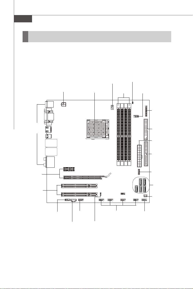
Quick Components Guide
Back Panel,
En-11
PCIE,
En-22
PCI,
En-23
JPWR2,
En-10
JAUD1,
En-17
JCD1,
En-17
J1394_1,
En-20
CPU,
En-5
JBAT1,
En-21
CPUFAN1
En-15
DDR2,
En-8
JUSB1~4,
En-19
JCI1,
En-15
JCOM1,
En-16
JLPT1,
En-18
FDD1,
En-13
JPWR1,
En-10
IDE1,
En-13
JTPM1,
En-16
SATA1~5,
En-14
SYSFAN1,
En-15
JFP1,
En-18
En-4
Page 14
CPU (Central Processing Unit)
When you are installing the CPU, make sure to install the cooler to prevent
overheating. If you do not have the CPU cooler, consult your dealer before turning
on the computer.
For the latest information about CPU, please visit http://global.msi.com.tw/index.php?
func=cpuform
Important
Overheating
Overheating will seriously damage the CPU and system. Always make sure
the cooling fan can work properly to protect the CPU from overheating. Make
sure that you apply an even layer of thermal paste (or thermal tape) between
the CPU and the heatsink to enhance heat dissipation.
Replacing the CPU
While replacing the CPU, always turn off the ATX power supply or unplug the
power supply’s power cord from the grounded outlet first to ensure the safety
of CPU.
Overclocking
This mainboard is designed to support overclocking. However, please make
sure your components are able to tolerate such abnormal setting, while
doing overclocking. Any attempt to operate beyond product specifications is
not recommended. We do not guarantee the damages or risks caused
by inadequate operation or beyond product specifications.
Engli sh
En-5
Page 15
MS-7552 Mainboard
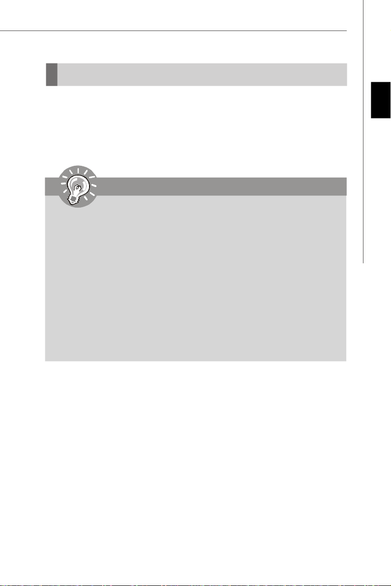
Gold arrow
Gold arrow
Gold arrow
Correct CPU placement
O
CPU Installation Procedures for Socket AM2+
1.Please turn off the power and
unplug the power cord before
installing the CPU.
2.Pull the lever sideways away
from the socket. Make sure to
raise the lever up to a 90-degree angle.
3.Look for the gold arrow of the
CPU. The gold arrow should
point as shown in the picture.
The CPU can only fit in the correct orientation.
4.If the CPU is correctly installed,
the pins should be completely
embedded into the socket and
can not be seen. Please note
that any violation of the correct
installation procedures may
cause permanent damages to
your mainboard.
Sliding
Plate
Open Lever
90 degree
5. Press the CPU down firmly into
the socket and close the lever.
As the CPU is likely to move while
the lever is being closed, always close the lever with your
fingers pressing tightly on top of
the CPU to make sure the CPU is
properly and completely embedded into the socket.
En-6
Page 16
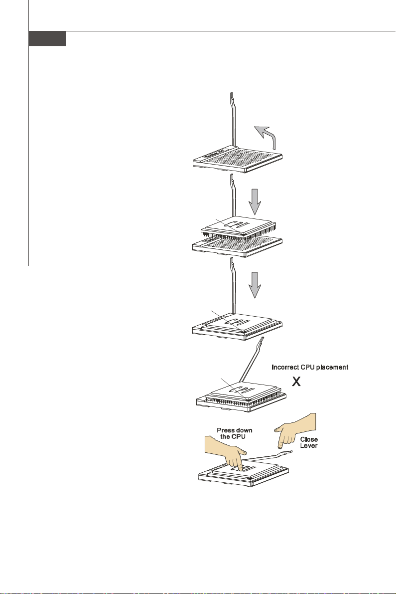
Installing AMD Socket AM2+ CPU Cooler Set
When you are installing the CPU, make sure the CPU has a heat sink and a
cooling fan attached on the top to prevent overheating. If you do not have the
heat sink and cooling fan, contact your dealer to purchase and install them before
turning on the computer.
Important
Mainboard photos shown in this section are for demonstration of the cooler
installation for Socket AM2+ CPUs only. The appearance of your mainboard
may vary depending on the model you purchase.
Engli sh
1.Position the cooling set onto the retention mechanism.
Hook one end of the clip to hook
first.
3.Fasten down the lever.
* While disconnecting the Safety Hook from the fixed bolt, it is necessary to
keep an eye on your fingers, because once the Safety Hook is disconnected
from the fixed bolt, the fixed lever will spring back instantly.
2. Then press down the other end of
the clip to fasten the cooling set on
the top of the retention mechanism.
Locate the Fix Lever and lift up it .
Fixed Lever
4.Attach the CPU Fan cable to the CPU
fan connector on the mainboard.
En-7
Page 17
MS-7552 Mainboard
1
2
3
Installed
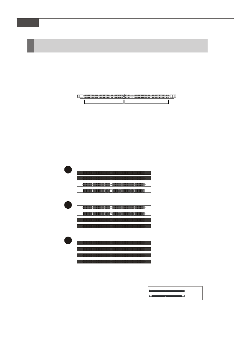
Memory
These DIMM slots are used for installing memory modules.
For more information on compatible components, please visit http://global.msi.com.
tw/index.php?func=testreport
DDR2
240-pin, 1.8V
64x2=128 pin56x2=112 pin
Dual-Channel Memory Population Rules
In Dual-Channel mode, the memory modules can transmit and receive data with two
data bus lines simultaneously. Enabling Dual-Channel mode can enhance the system
performance. Please refer to the following illustrations for population rules under
Dual-Channel mode.
DIMM1
DIMM2
DIMM3
DIMM4
DIMM1
DIMM2
DIMM3
DIMM4
DIMM1
DIMM2
DIMM3
DIMM4
Empty
En-8
Page 18
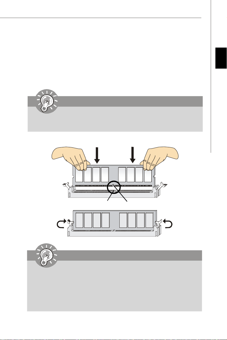
Installing Memory Modules
1. The memory module has only one notch on the center and will only fit in the right
orientation.
2. Insert the memory module vertically into the DIMM slot. Then push it in until the
golden finger on the memory module is deeply inserted in the DIMM slot. The plastic
clip at each side of the DIMM slot will automatically close when the memory module
is properly seated.
Important
You can barely see the golden finger if the memory module is properly inserted
in the DIMM slot.
3. Manually check if the memory module has been locked in place by the DIMM slot
clips at the sides.
Engli sh
Volt
Notch
Important
-DDR2 memory modules are not interchangeable with DDR and the DDR2
standard is not backwards compatible. You should always install DDR2
memory modules in the DDR2 DIMM slots.
-In Dual-Channel mode, make sure that you install memory modules of the
same type and density in different channel DIMM slots.
-To enable successful system boot-up, always insert the memory modules
into the DIMM1 first.
En-9
Page 19
MS-7552 Mainboard
Power Supply
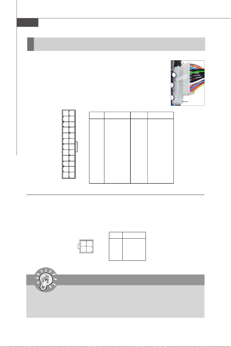
ATX 24-Pin Power Connector: JPWR1
This connector allows you to connect an ATX 24-pin power supply.
To connect the ATX 24-pin power supply, make sure the plug of the
power supply is inserted in the proper orientation and the pins are
aligned. Then push down the power supply firmly into the connector.
You may use the 20-pin ATX power supply as you like. If you’d like
to use the 20-pin ATX power supply, please plug your power supply along with pin 1 & pin 13 (refer to the image at the right hand).
Pin Definition
PIN SIGNAL
13 +3.3V
14 -12V
15 GND
16 PS-ON#
17 GND
18 GND
19 GND
20 Res
21 +5V
22 +5V
23 +5V
24 GND
JPWR1
12
1
24
13
PIN SIGNAL
1 +3.3V
2 +3.3V
3 GND
4 +5V
5 GND
6 +5V
7 GND
8 PWR OK
9 5VSB
10 +12V
11 +12V
12 +3.3V
ATX 4-Pin Power Connector: JPWR2
This 12V power connector JPW1 is used to provide power to the CPU.
pin 13
pin 12
JPWR2
4
3
2
1
PIN SIGNAL
1 GND
2 GND
3 12V
4 12V
Important
1. Maker sure that all the connectors are connected to proper ATX power supplies to ensure stable operation of the mainboard.
2. Power supply of 450 watts (and above) is highly recommended for system
stability.
En-10
Pin Definition
Page 20
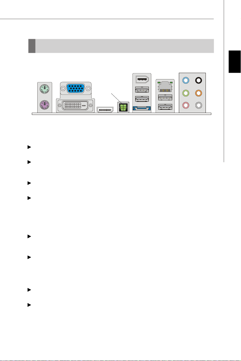
Back Panel
1394 Port
Keyboard
Mouse
VGA Port
DVI-D Port
Optical
S/PDIF-Out
HDMI Port
USB Ports
LAN
Line-Out
USB Ports
Line-In
Mic
RS-Out
CS-Out
SS-Out
eSATA Port
Keyboard / Mouse
The standard PS/2® keyboard / mouse DIN connector is for a PS/2® keyboard / mouse.
USB Port
The USB (Universal Serial Bus) port is for attaching USB devices such as keyboard,
mouse, or other USB-compatible devices.
VGA Port
The DB15-pin female connector is provided for monitor.
DVI-D Port
The DVI-D (Digital Visual Interface-Digital) connector allows you to connect a LCD
monitor. It provides a high-speed digital interconnection between the computer and
its display device. To connect an LCD monitor, simply plug your monitor cable into the
DVI connector, and make sure that the other end of the cable is properly connected
to your monitor (refer to your monitor manual for more information.)
Optical S/PDIF-Out
This SPDIF (Sony & Philips Digital Interconnect Format) connector is provided for
digital audio transmission to external speakers through an optical fiber cable.
HDMI Port
The High-Definition Multimedia Interface (HDMI) is an all-digital audio/video interface
capable of transmitting uncompressed streams. HDMI supports all TV format, including standard, enhanced, or high-definition video, plus multi-channel digital audio on a
single cable.
1394 Port
The IEEE1394 port on the back panel provides connection to IEEE1394 devices.
eSATA Port
The eSATA port is for attaching the eSATA external hard drive.
English
En-11
Page 21
MS-7552 Mainboard
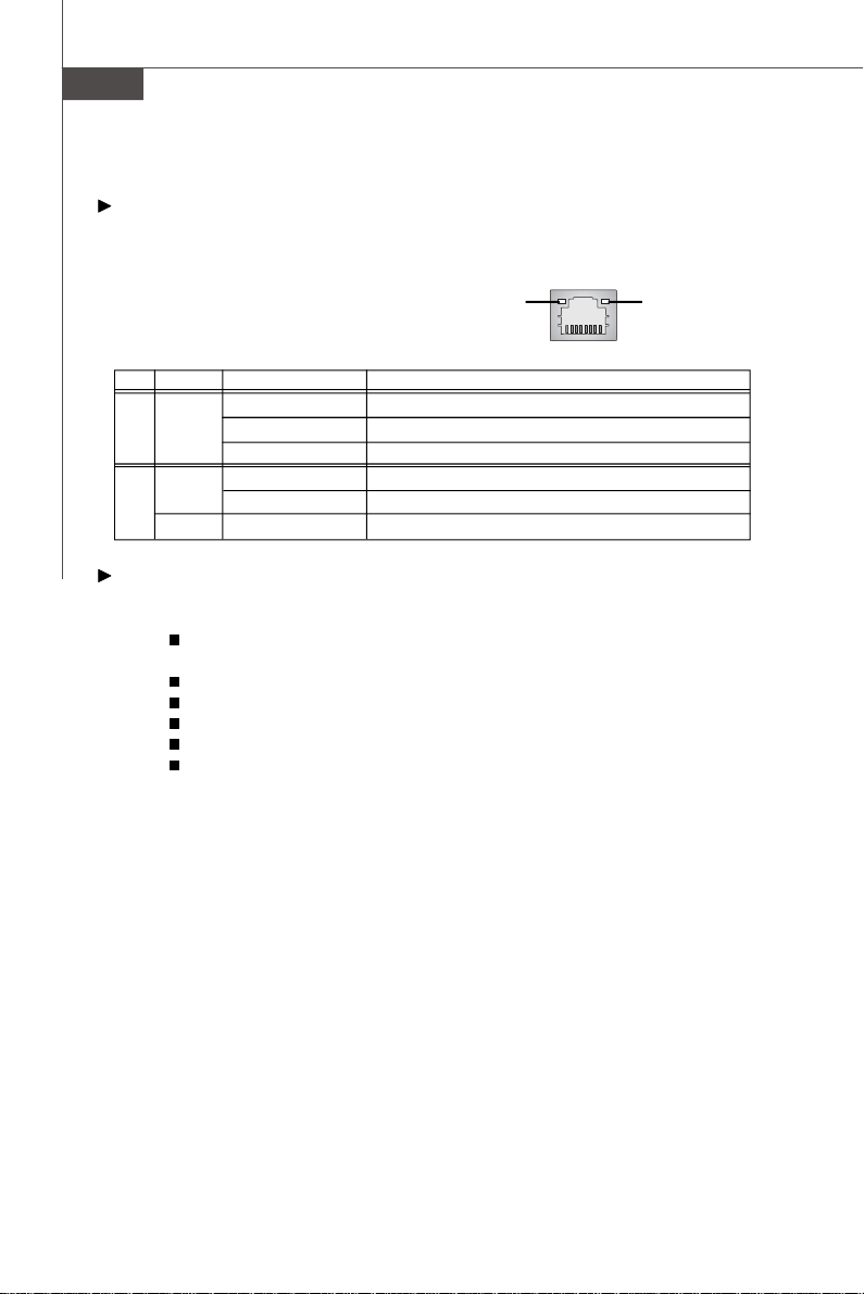
LAN
The standard RJ-45 LAN jack is for connection to the Local Area Network (LAN). You
can connect a network cable to it.
Green / OrangeYellow
LED Color LED State Condition
Off LAN link is not established.
Left Yellow On (steady state) LAN link is established.
On (brighter & pulsing)The computer is communicating with another computer on the LAN.
Green Off 10 Mbit/sec data rate is selected.
Right On 100 Mbit/sec data rate is selected.
Orange On 1000 Mbit/sec data rate is selected.
Audio Ports
These audio connectors are used for audio devices. You can differentiate the color
of the audio jacks for different audio sound effects.
Line-In (Blue) - Line In is used for external CD player, tapeplayer or
other audio devices.
Line-Out (Green) - Line Out, is a connector for speakers or headphones.
Mic (Pink) - Mic, is a connector for microphones.
RS-Out (Black) - Rear-Surround Out in 4/ 5.1/ 7.1 channel mode.
CS-Out (Orange) - Center/ Subwoofer Out in 5.1/ 7.1 channel mode.
SS-Out (Gray) - Side-Surround Out 7.1 channel mode.
En-12
Page 22
Connectors
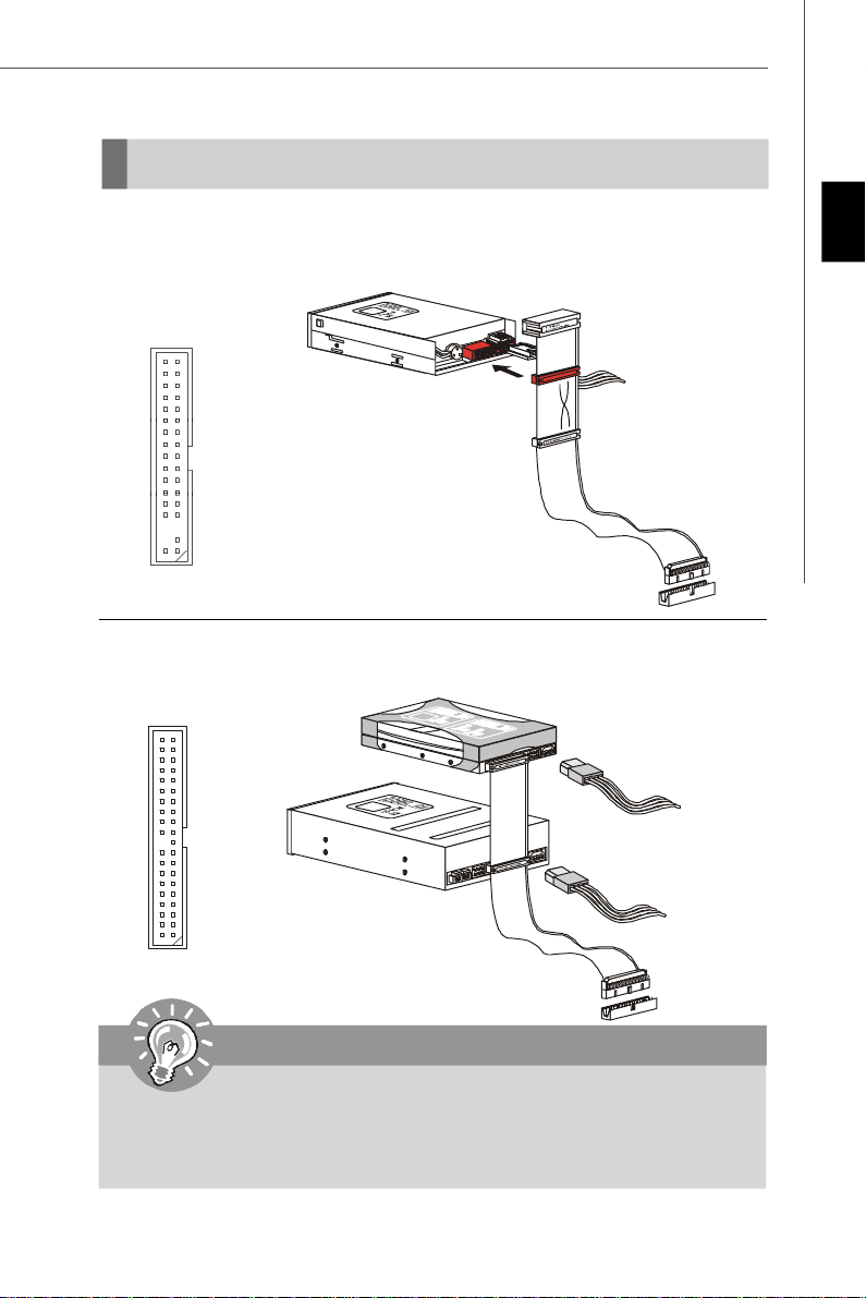
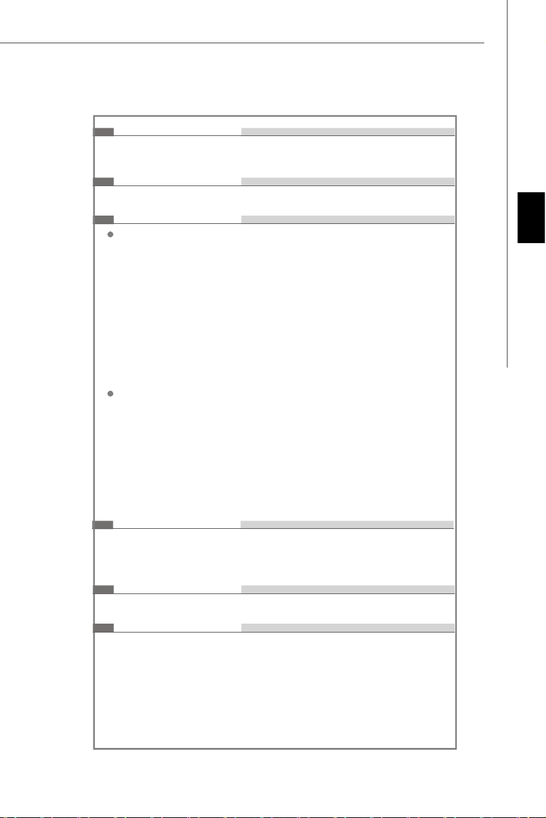
Floppy Disk Drive Connector: FDD1
This connector supports 360KB, 720KB, 1.2MB, 1.44MB or 2.88MB floppy disk drive.
FDD1
IDE Connector: IDE1
This connector supports IDE hard disk drives, optical disk drives and other IDE devices.
IDE1
English
Important
If you install two IDE devices on the same cable, you must configure the
drives separately to master / slave mode by setting jumpers. Refer to IDE
device’s documentation supplied by the vendors for jumper setting
instructions.
En-13
Page 23
MS-7552 Mainboard
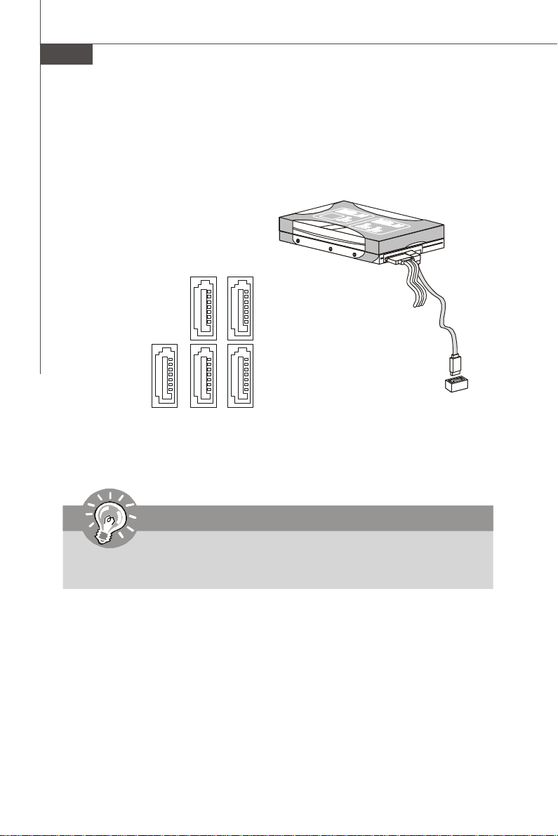
Serial ATA Connector: SATA1~ SATA5
This connector is a high-speed Serial ATA interface port. Each connector can connect
to one Serial ATA device.
SATA4
SATA1
SATA2
SATA5
SATA3
Important
Please do not fold the Serial ATA cable into 90-degree angle. Otherwise,
data loss may occur during transmission.
En-14
Page 24
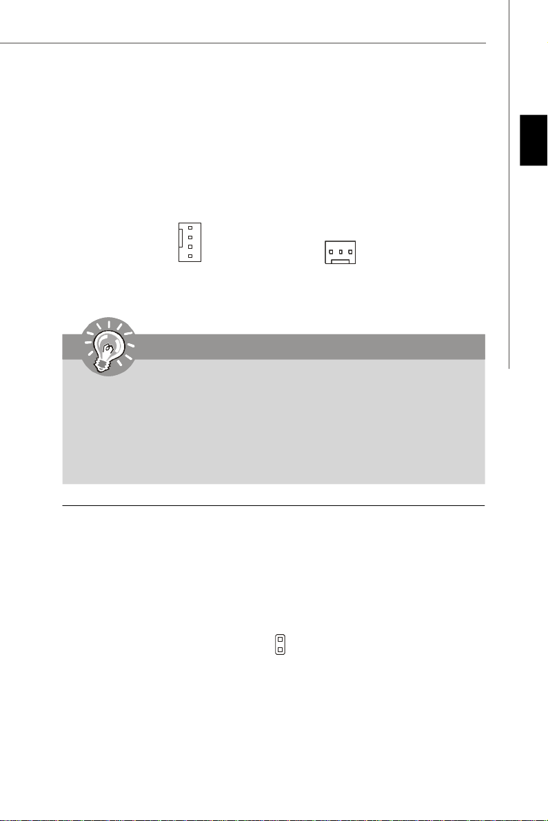
Fan Power Connectors: CPUFAN1, SYSFAN1
The fan power connectors support system cooling fan with +12V. When connecting
the wire to the connectors, always note that the red wire is the positive and should
be connected to the +12V; the black wire is Ground and should be connected to GND.
If the mainboard has a System Hardware Monitor chipset on-board, you must use a
specially designed fan with speed sensor to take advantage of the CPU fan control.
English
GND
+12V
SENSOR
Control
CPUFAN1
+1 2V
SE NS OR
GND
SYSFAN1
Important
1.Please refer to the recommended CPU fans at processor’s official website
or consult the vendors for proper CPU cooling fan.
2.CPUFAN1 supports fan control. You can install Dual Core Center utility
that will automatically control the CPU fan speed according to the actual
CPU temperature.
3. Fan cooler set with 3 or 4 pins power connector are both available for
CPUFAN1.
Chassis Intrusion Connector: JCI1
This connector connects to the chassis intrusion switch cable. If the chassis is
opened, the chassis intrusion mechanism will be activated. The system will record
this status and show a warning message on the screen. To clear the warning, you
must enter the BIOS utility and clear the record.
GND
CINTRU
JCI1
2
1
En-15
Page 25
MS-7552 Mainboard
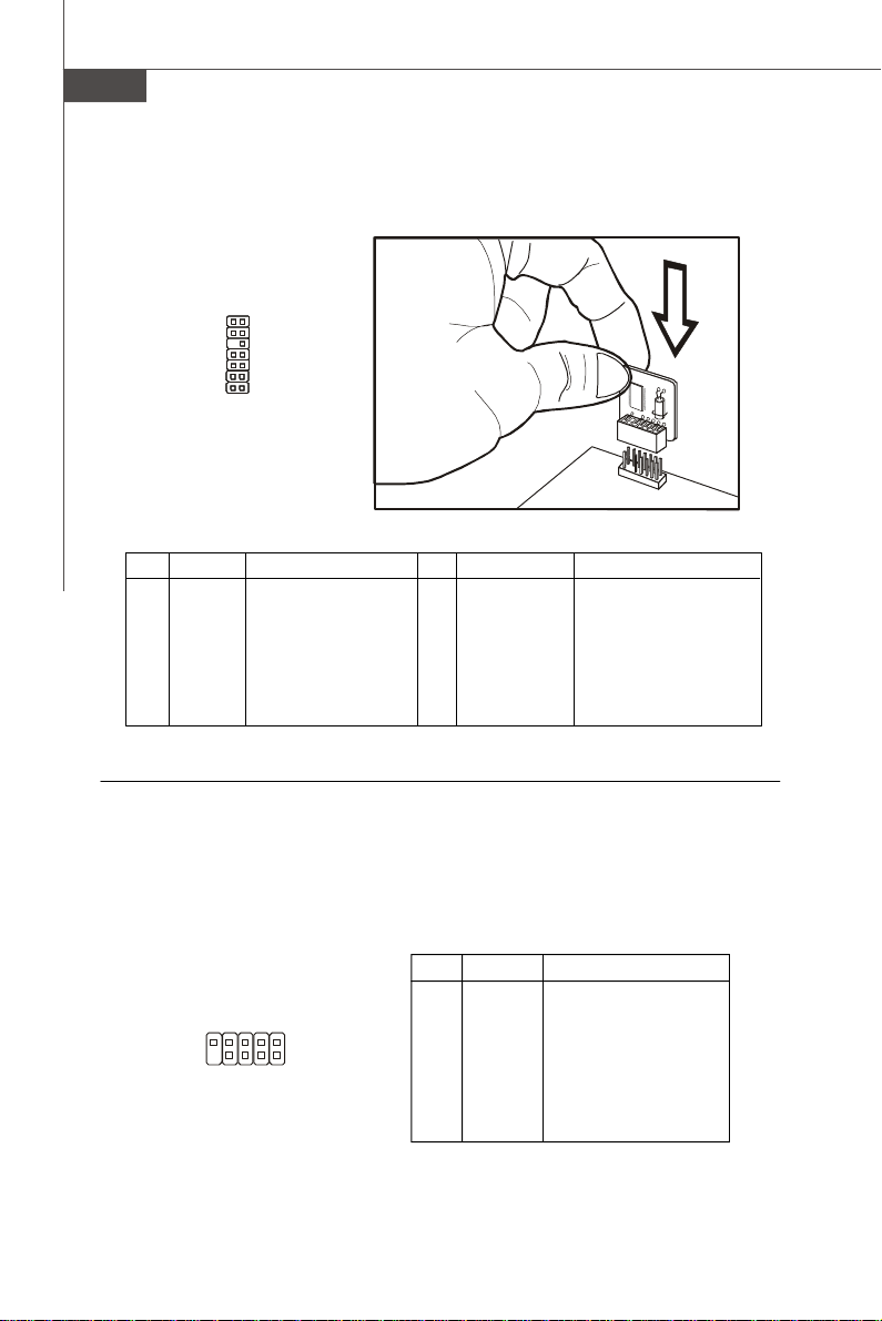
TPM Module Connector: JTPM1
This connector connects to a TPM (Trusted Platform Module) module (optional). Please
refer to the TPM security platform manual for more details and usages.
13
14
2 1
JTPM1
Pin Signal Description Pin Signal Description
1 LCLK LPC clock 2 3V_STB 3V standby power
3 LRST# LPC reset 4 VCC3 3.3V power
5 LAD0 LPC address & data pin0 6 SIRQ Serial IRQ
7 LAD1 LPC address & data pin1 8 VCC5 5V power
9 LAD2 LPC address & data pin2 10 KEY No pin
11 LAD3 LPC address & data pin3 12 GND Ground
13 LFRAME# LPC Frame 14 GND Ground
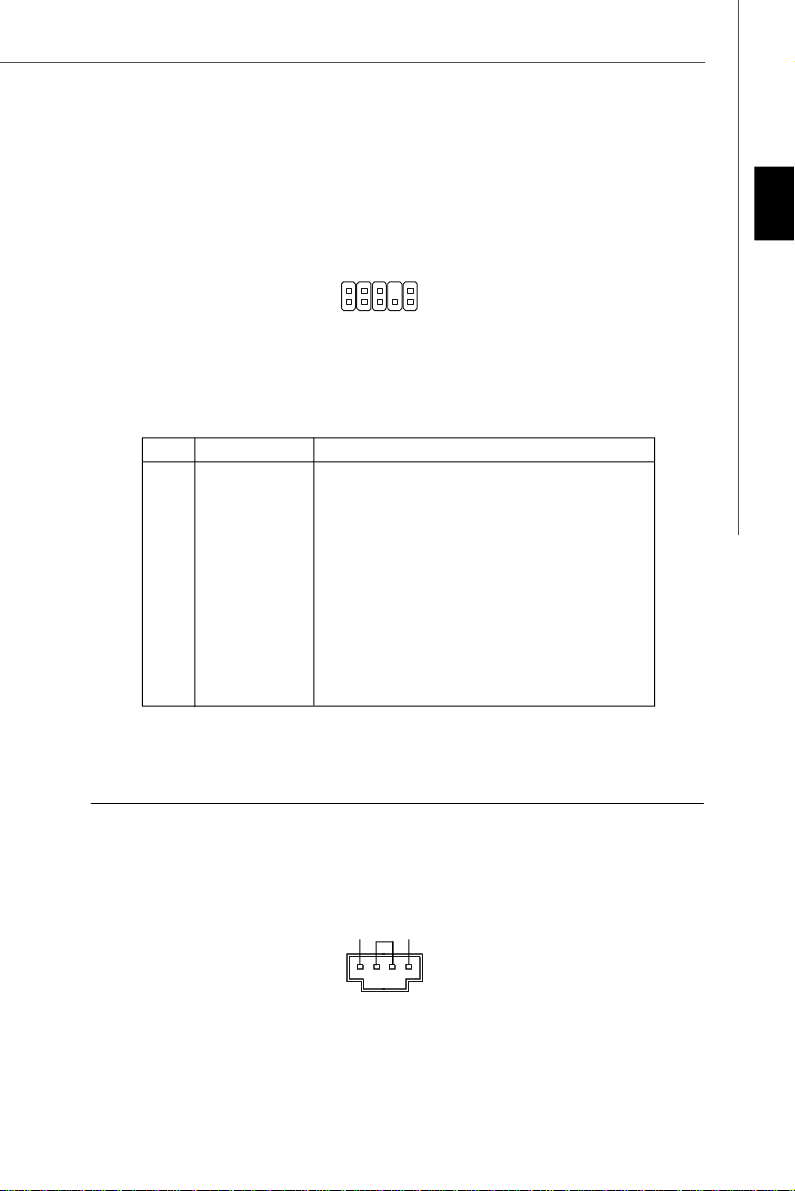
Serial Port Connector: JCOM 1
This connector is a 16550A high speed communication port that sends/receives 16
bytes FIFOs. You can attach a serial device.
Pin Definition
PIN SIGNAL DESCRIPTION
1 DCD Data Carry Detect
2 SIN Serial In or Receive Data
3 SOUT Serial Out or Transmit Data
4 DTR Data Terminal Ready
5 GND Ground
6 DSR Data Set Ready
7 RTS Request To Send
8 CTS Clear To Send
9 RI Ring Indicate
En-16
JCOM1
9
1
2
Page 26
Front Panel Audio Connector: JAUD1
This connector allows you to connect the front panel audio and is compliant with
Intel® Front Panel I/O Connectivity Design Guide.
English
2
1
10
9
JAUD1
HD Audio Pin Definition
PIN SIGNAL DESCRIPTION
1 MIC_L Microphone - Left channel
2 GND Ground
3 MIC_R Microphone - Right channel
4 PRESENCE# Active low signal-signals BIOS that a High Definition Audio dongle
5 LINE out_R Analog Port - Right channel
6 MIC_JD Jack detection return from front panel microphone JACK1
7 Front_JD Jack detection sense line from the High Definition Audio CODEC
8 NC No control
9 LINE out_L Analog Port - Left channel
10 LINEout_JD Jack detection return from front panel JACK2
is connected to the analog header. PRESENCE# = 0 when a
High Definition Audio dongle is connected
jack detection resistor network
CD-In Connector: JCD1
This connector is provided for external audio input.
JCD1
GND
R L
En-17
Page 27
MS-7552 Mainboard
Front Panel Connector: JFP1
These connectors are for electrical connection to the front panel switches and LEDs.
The JFP1 is compliant with Intel® Front Panel I/O Connectivity Design Guide.
Power
Power
LED
Switch
-
+
2
JFP1
1
+
HDD
LED
JFP1 Pin Definition
PIN SIGNAL DESCRIPTION
1 HD_LED + Hard disk LED pull-up
2 FP PWR/SLP MSG LED pull-up
3 HD_LED - Hard disk active LED
4 FP PWR/SLP MSG LED pull-up
5 RST_SW - Reset Switch low reference pull-down to GND
6 PWR_SW + Power Switch high reference pull-up
7 RST_SW + Reset Switch high reference pull-up
8 PWR_SW - Power Switch low reference pull-down to GND
9 RSVD_DNU Reserved. Do not use.
-
-
+
Reset
Switch
10
9
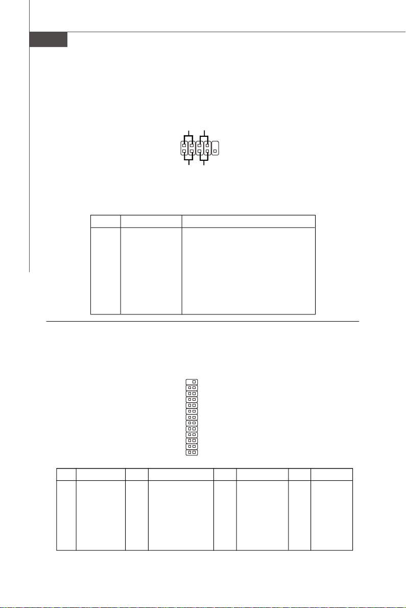
Parallel Port Header: JLPT1
This connector is used to connect an optional parallel port bracket. The parallel port
is a standard printer port that supports Enhanced Parallel Port (EPP) and Extended
Capabilities Parallel Port (ECP) mode.
PIN SIGNAL PIN SIGNAL
1 RSTB# 2 AFD#
3 PRND0 4 ERR#
5 PRND1 6 PINIT#
7 PRND2 8 LPT_SLIN#
9 PRND3 10 GND
11 PRND4 12 GND
13 PRND5 14 GND
En-18
JLPT1
26 25
2
1
PIN SIGNAL PIN SIGNAL
15 PRND6 16 GND
17 PRND7 18 GND
19 ACK# 20 GND
21 BUSY 22 GND
23 PE 24 GND
25 SLCT 26 Key (No Pin)
Page 28
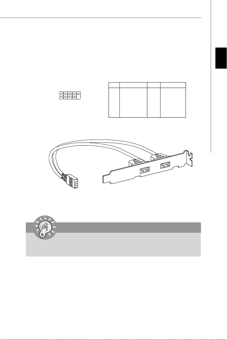
Front USB Connector: JUSB1 ~ 4
These connectors, compliant with Intel® I/O Connectivity Design Guide, is ideal for
connecting high-speed USB interface peripherals such as USB HDD, digital cameras,
MP3 players, printers, modems and the like.
Pin Definition
JUSB1~4
2
1
10
9
PIN SIGNAL PIN SIGNAL
1 VCC 2 VCC
3 USB0- 4 USB1-
5 USB0+ 6 USB1+
7 GND 8 GND
9 Key (no pin) 10 USBOC
USB 2.0 Bracket
(Optional)
English
Important
Note that the pins of VCC and GND must be connected correctly to avoid
possible damage.
En-19
Page 29
MS-7552 Mainboard
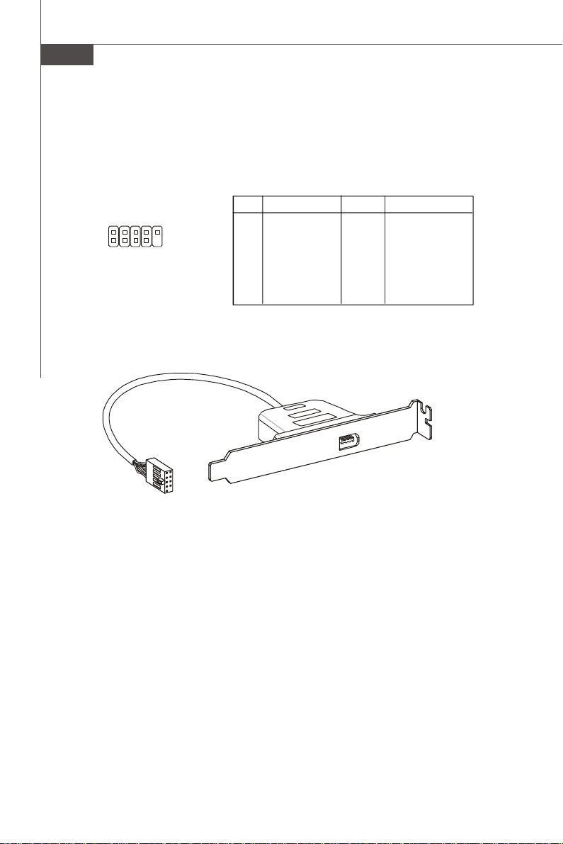
IEEE1394 Connector: J1394_1
This connector allows you to connect the IEEE1394 device via an optional IEEE1394
bracket.
Pin Definition
PIN SIGNAL PIN SIGNAL
2
1
J1394_1
10
9
1 TPA+ 2 TPA-
3 Ground 4 Ground
5 TPB+ 6 TPB-
7 Cable power 8 Cable power
9 Key (no pin) 10 Ground
En-20
IEEE1394 Bracket (Optional)
Page 30
Jumpers
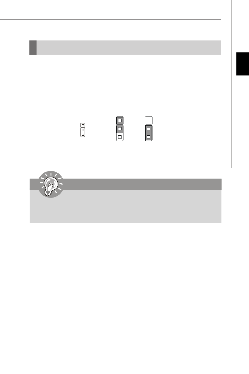
Clear CMOS Jumper: JBAT1
There is a CMOS RAM onboard that has a power supply from an external battery to
keep the data of system configuration. With the CMOS RAM, the system can automatically boot OS every time it is turned on. If you want to clear the system configuration,
set the jumper to clear data.
1
JBAT1
1
3
Keep Data
1
3
Clear Data
Important
You can clear CMOS by shorting 2-3 pin while the system is off. Then return
to 1-2 pin position. Avoid clearing the CMOS while the system is on; it will
damage the mainboard.
English
En-21
Page 31

MS-7552 Mainboard
Slots
PCI (Peripheral Component Interconnect) Express Slot
The PCI Express slot supports the PCI Express interface expansion card.
The PCI Express 2.0x16 supports up to 8 GB/s transfer rate.
The PCI Express x1 supports up to 250 MB/s transfer rate.
PCI Express 2.0x16 Slot
PCI Express x 1 Slot
Important
When adding or removing expansion cards, make sure that you unplug the
power supply first. Meanwhile, read the documentation for the expansion
card to configure any necessary hardware or software settings for the expansion card, such as jumpers, switches or BIOS configuration.
En-22
Page 32

PCI (Peripheral Component Interconnect) Slot
The PCI slot supports LAN card, SCSI card, USB card, and other add-on cards that
comply with PCI specifications.
32-bit PCI Slot
Important
When adding or removing expansion cards, make sure that you unplug the
power supply first. Meanwhile, read the documentation for the expansion card
to configure any necessary hardware or software settings for the expansion
card, such as jumpers, switches or BIOS configuration.
PCI Interrupt Request Routing
The IRQ, acronym of interrupt request line and pronounced I-R-Q, are hardware lines
over which devices can send interrupt signals to the microprocessor. The PCI IRQ
pins are typically connected to the PCI bus pins as follows:
English
Order 1 Order 2 Order 3 Order 4
PCI Slot 1 INT A# INT B# INT C# INT D#
PCI Slot 2 INT B# INT C# INT D# INT A#
En-23
Page 33

MS-7552 Mainboard
Hybrid CrossfireTM Technology
Hybrid CrossfireXTM technology brings multi-GPU performance capabilities by enabling an AMD 780 integrated graphics processor and a discrete graphics processor
to operate simultaneously with combined output to a single display for blisteringlyfast frame rates. Unleash the graphics performance.
System Request
1. Hybrid CrossfireXTM is only supported with the Vista operating system.
2. Graphic card based on an ATI RadeonTM HD 2400 Series2, ATI RadeonTM HD 3400
Series or ATI Mobility RadeonTM HD 3400 Series graphics processor.
3. Mainboard based on an AMD 780 integrated chipset.
Enabling Hybrid CrossfireTM Technology
Power off the system and install the ATI graphic card that supports Hybrid CrossfireX
technology. After then, power on the system and install the driver that Hybrid
CrossfireX technology. Restart the system and wait for the ATI Icon to show in the
System Tray. Click the icon and then the following aspect appears in Catalyst™
Control Center:
1. Select the Advanced View from the
view drop menu.
En-24
Page 34

2. From the Graphics Settings tree in the CatalystTM Control Center, click CrossFireTM.
3. From the Graphics Adapter list, select the graphics card that acts as the Display
GPU.
4. Select Enable CrossFire
TM
5. Click Apply.
When Hybrid CrossfireX is enabled, GPU Accelerated Physics is automatically disabled for all cards in the configuration as are all displays except the one used by
Hybrid CrossfireX.
More details please refer to http://game.amd.com/us-en/crossfirex_hybrid.aspx
Important
Changing integrated graphic memory operating mode may cause Hybrid
Crossfire fail. To avoid the issue, please follow the steps below to setup
the system:
1.Disable the Hybrid Crossfire in Catalyst Control Center.
2.Reboot into BIOS
3.Select the option in Advanced BIOS Features -> Chipset Feature ->
On-Chip VGA
4.Save BIOS settings and reboot
5.Enable the Hybrid Crossfire in Catalyst Control Center.
English
En-25
Page 35

MS-7552 Mainboard
BIOS Setup
This chapter provides basic information on the BIOS Setup program and allows you to
configure the system for optimum use. You may need to run the Setup program
when:
* An error message appears on the screen during the system booting up, and requests you to run BIOS SETUP.
* You want to change the default settings for customized features.
Important
1.The items under each BIOS category described in this chapter are under
continuous update for better system performance. Therefore, the description
may be slightly different from the latest BIOS and should be held for reference
only.
2.Upon boot-up, the 1st line appearing after the memory count is the BIOS
version. It is usually in the format:
1st digit refers to BIOS maker as A = AMI, W = AWARD, and P = PHOENIX.
2nd - 5th digit refers to the model number.
6th refers to the Chipset vender as A = AMD, I = Intel, V = VIA, N = Nvidia, U =
ULi.
7th - 8th digit refers to the customer as MS = all standard customers.
V1.0 refers to the BIOS version.
082208 refers to the date this BIOS was released.
A7552AMS V1.0 082208 where:
En-26
Page 36

Entering Setup
Power on the computer and the system will start POST (Power On Self Test) process.
When the message below appears on the screen, press <DEL> key to enter Setup.
Press DEL to enter SETUP
If the message disappears before you respond and you still wish to enter Setup,
restart the system by turning it OFF and On or pressing the RESET button. You may
also restart the system by simultaneously pressing <Ctrl>, <Alt>, and <Delete> keys.
Getting Help
After entering the Setup menu, the first menu you will see is the Main Menu.
Main Menu
The main menu lists the setup functions you can make changes to. You can use the
arrow keys (↑↓ ) to select the item. The on-line description of the highlighted setup
function is displayed at the bottom of the screen.
Sub-Menu
If you find a right pointer symbol (as shown in the right view)
appears to the left of certain fields that means a sub-menu
containing additional options can be launched from this field.
You can use control keys (↑↓ ) to highlight the field and
press <Enter> to call up the sub-menu. Then you can use the control keys to enter
values and move from field to field within a sub-menu. If you want to return to the
main menu, just press <Esc >.
General Help <F1>
The BIOS setup program provides a General Help screen. You can call up this screen
from any menu by simply pressing <F1>. The Help screen lists the appropriate keys
to use and the possible selections for the highlighted item. Press <Esc> to exit the
Help screen.
English
En-27
Page 37

MS-7552 Mainboard
The Main Menu
Once you enter AMI® or AWARD® BIOS CMOS Setup Utility, the Main Menu will appear
on the screen. The Main Menu allows you to select from ten setup functions and two
exit choices. Use arrow keys to select among the items and press <Enter> to accept
or enter the sub-menu.
Standard CMOS Features
Use this menu for basic system configurations, such as time, date etc.
Advanced BIOS Features
Use this menu to setup the items of special enhanced features.
Integrated Peripherals
Use this menu to specify your settings for integrated peripherals.
Power Management Setup
Use this menu to specify your settings for power management.
H/W Monitor
This entry shows your PC health status.
BIOS Setting Password
Use this menu to set the Password.
Cell Menu
Use this menu to specify your settings for frequency/voltage control and overclocking.
Load Fail-Safe Defaults
Use this menu to load the default values set by the BIOS vendor for stable system
performance.
Load Optimized Defaults
Use this menu to load the default values set by the mainboard manufacturer specifically for optimal performance of the mainboard.
Save & Exit Setup
Save changes to CMOS and exit setup.
Exit Without Saving
Abandon all changes and exit setup.
En-28
Page 38

When enter the BIOS Setup utility, follow the processes below for general use.
1. Load Optimized Defaults : Use control keys (↑↓) to highlight the Load Opti-
mized Defaults field and press <Enter> , a message as below appears:
Select [Ok] and press Enter to load the default settings for optimal system
performance.
2. Setup Date/ Time : Select the Standard CMOS Features and press <Enter> to
enter the Standard CMOS Features-menu. Adjust the Date, Time fields.
3. Save & Exit Setup : Use control keys (↑↓) to highlight the Save & Exit Setup
field and press <Enter> , a message as below appears:
English
Select [Ok] and press Enter to save the configurations and exit BIOS Setup utility.
Important
The configuration above are for general use only. If you need the detailed
settings of BIOS, please see the manual in English version on MSI website.
En-29
Page 39

MS-7552 Mainboard
4. Cell Menu Introduction : This menu is for advanced user who want to overclock
the mainboard.
Important
Change these settings only if you are familiar with the chipset.
Current CPU / DRAM Frequency
These items show the current clocks of CPU and Memory speed. Read-only.
AMD Cool’n’Quiet
The Cool’n’ Quiet technology can effectively and dynamically lower CPU speed and
power consumption.
En-30
Page 40

Important
To ensure that Cool’n’Quiet function is activated and will be working properly, it is
required to double confirm that:
1.Run BIOS Setup, and select Cell Menu.
Under Cell Menu, find AMD
Cool’n’Quiet, and set this item to
“Enable.”
2.Enter Windows, and select [Start]->
[Settings]->[Control Pannel]->[Power
Options]. Enter Power Options Prop-
erties tag, and select Minimal Power
Management under Power schemes.
Adjust CPU FSB Frequency (MHz)
This item allows you to adjust the CPU FSB frequency.
Adjust CPU Ratio
This item lets you to adjust the CPU ratio. It is available only when the processor
supports this function.
Adjusted CPU Frequency (MHz)
It shows the adjusted CPU frequency (FSB x Ratio). Read-only.
Advance DRAM Configuration
Press <Enter> to enter the sub-menu and the following screen appears.
English
DRAM Timing Mode
Setting to [Auto] enables DRAM CAS# Latency automatically to be determined by
BIOS based on the configurations on the SPD (Serial Presence Detect) EEPROM
on the DRAM module.
1T/2T Memory Timing
This field controls the SDRAM command rate. Selecting [1T] makes SDRAM
signal controller to run at 1T (T=clock cycles) rate. Selecting [2T] makes SDRAM
signal controller run at 2T rate.
En-31
Page 41

MS-7552 Mainboard
DCT Unganged Mode
This is used to enable/ disable the DCT Unganged Mode (for Phenom only).
FSB/DRAM Ratio
This item will allow you to adjust the ratio of FSB to memory.
Adjusted DRAM Frequency (MHz)
It shows the adjusted DRAM frequency. Read-only.
HT Link Speed
This item allows you to set the Hyper-Transport Link speed. Setting to [Auto], the
system will detect the HT link speed automatically.
Auto Disable DRAM/PCI Frequency
When set to [Enabled], the system will remove (turn off) clocks from empty DRAM/PCI
slots to minimize the electromagnetic interference (EMI).
Adjust PCI-E Frequency (MHz)
This field allows you to select the PCIE frequency (in MHz).
CPU Voltage (V)/ DRAM Voltage (V)/ SB Voltage (V)/ NB Voltage (V)
These items are used to asjust the voltage of CPU, Memory, FSB and chipset.
Spread Spectrum
When the motherboard’s clock generator pulses, the extreme values (spikes) of the
pulses create EMI (Electromagnetic Interference). The Spread Spectrum function
reduces the EMI generated by modulating the pulses so that the spikes of the pulses
are reduced to flatter curves. If you do not have any EMI problem, leave the setting at
Disabled for optimal system stability and performance. But if you are plagued by EMI,
set to Enabled for EMI reduction. Remember to disable Spread Spectrum if you are
overclocking because even a slight jitter can introduce a temporary boost in clock
speed which may just cause your overclocked processor to lock up.
Important
1.If you do not have any EMI problem, leave the setting at [Disabled] for
optimal system stability and performance. But if you are plagued by EMI,
select the value of Spread Spectrum for EMI reduction.
2.The greater the Spread Spectrum value is, the greater the EMI is reduced,
and the system will become less stable. For the most suitable Spread
Spectrum value, please consult your local EMI regulation.
3.Remember to disable Spread Spectrum if you are overclocking because
even a slight jitter can introduce a temporary boost in clock speed which
may just cause your overclocked processor to lock up.
En-32
Page 42

Software Information
Take out the Driver/Utility CD that is included in the mainboard package, and place it into
the CD-ROM drive. The installation will auto-run, simply click the driver or utility and
follow the pop-up screen to complete the installation. The Driver/Utility CD contains
the:
Driver menu - The Driver menu shows the available drivers. Install the driver by your
desire and to activate the device.
Utility menu - The Utility menu shows the software applications that the mainboard
supports.
WebSite menu- The WebSite menu shows the necessary websites.
Important
Please visit the MSI website to get the latest drivers and BIOS for better
system performance.
English
En-33
Page 43

KA780GM Serie
Benutzerhandbuch
Deutsch
Deutsch
De-1
Page 44

MS-7552 Mainboard
Spezifikationen
Prozessoren
- Unterstützt AMD® Athlon64 / Athlon64 X2 /AM2+ Prozessoren
- Unterstützt Lüftersteuerung über 4 Stiftleisten
- Unterstützt die CPU-Frenquenz bis zu 5000+ und höher
(Weitere CPU Informationen finden Sie unter
http://global.msi.com.tw/index.php?func=cpuform)
HyperTransport
- Unterstützt HyperTransport 3.0
Chipsatz
- North-Bridge: AMD 780G
- South-Birdge: AMD SB700
Speicher
- DDR2 533/667/800/1066 SDRAM (240Pin / 1.8V)
- 4 DDR2 DIMMs (max. 16GB)
(Weitere Informationen zu kompatiblen Speichermodulen finden
Sie unter http://global.msi.com.tw/index.php?func=testreport)
Sideport Speicher
- DDR3 SDRAM 1Gbit (optional)
LAN
- Unterstützt LAN 10/100/1000 Fast Ethermet über RTL8111C
IEEE 1394
- Onboard Chip über JMicron 381
- Übertragungsgeschwindigkeit von bis zu 400Mb/s
Audio
- Onboard Soundchip Realtek® ALC888
- 8-Kanal Audio-Ausgang mit “Jack Sensing” Funktion
- Erfüllt die Azalia Spezifikationen
IDE
- 1 IDE Port über SB700
- Unterstützt die Betriebmodi mit Ultra DMA 66/100/133
- Unterstützt die Betriebmodi mit PIO, Bus Mastering
SATA
- SATA II Ports über SB700
- Unterstützt 6 SATA II Geräte (einbegriffen 1 eSATA)
- Unterstützt Datenübertragungsraten von bis zu 3 Gb/s
De-2
Page 45
Diskette
- 1 Disketten Anschluss
- Unterstützt 1 FDD mit 360KB, 720KB, 1.2MB, 1.44MB und 2.88MB
RAID
- Unterstützt die Modi RAID 0/ 1/ 0+1 über SB700
Anschlüsse
Hintere Ein-/ und Ausgänge
- 1 PS/2 Mausanschluss
- 1 PS/2 Tastaturanschluss
- 1 VGA Anschluss
- 1 DVI-D Anschluss
- 1 HDMI Anschluss
- 1 optischer SPDIF Anschluss
- 1 IEEE 1394 Anschluss
- 4 USB 2.0 Anschlüsse
- 1 eSATA Anschluss
- 1 LAN Anschluss
- 6 Audiobuchsen
On-Board Stiftleiste/ Anschlüsse
- 4 USB 2.0 Stiftleisten
- 1 COM Stiftleiste
- 1 CD-Stiftleiste für Audio Eingang
- 1 Audio Stiftleiste für Gehäuse Audio Ein-/ Ausgänge
- 1 IEEE 1394 Stiftleiste
- 1 Gehäusekontaktschalter
- 1 TPM Schnittstelle
- 1 JLPT Stiftleiste
Steckplätze
- 1 PCI Express x16 -Steckplatz
- 1 PCI Express x1-Steckplatz
- 2 PCI-Steckplätze
Form Faktor
- M-ATX (24.4cm X 24.4 cm)
Montage
- 6 Montagebohrungen
Deutsch
De-3
Page 46

MS-7552 Mainboard
Komponenten-Übersicht
Back Panel,
De-11
PCIE,
De-22
PCI,
De-23
JPWR2,
De-10
JAUD1,
De-17
JCD1,
De-17
J1394_1,
De-20
CPU,
De-5
JBAT1,
De-21
CPUFAN1
De-15
DDR2,
De-8
JUSB1~4,
De-19
JCI1,
De-15
JCOM1,
De-16
JLPT1,
De-18
FDD1,
De-13
JPWR1,
De-10
IDE1,
De-13
JTPM1,
De-16
SATA1~5,
De-14
SYSFAN1,
De-15
JFP1,
De-18
De-4
Page 47

CPU (Central Processing Unit)
Wenn Sie die CPU einbauen, stellen Sie bitte sicher, dass Sie auf der CPU
einen Kühler anbringen, um Überhitzung zu vermeiden. Verfügen Sie über
keinen Kühler, setzen Sie sich bitte mit Ihrem Händler in Verbindung, um einen solchen
zu erwerben und zu installieren.
Um die neuesten Informationen zu unterstützten Prozessoren zu erhalten, besuchen
Sie bitte http://global.msi.com.tw/index.php?func=cpuform
Wichtig
Überhitzung
Überhitzung beschädigt die CPU und das System nachhaltig. Stellen Sie stets
eine korrekte Funktionsweise des CPU Kühlers sicher, um die CPU vor
Überhitzung zu schützen. Überprüfen Sie eine gleichmäßige Schicht der
thermischen Paste (oder thermischen Klebeandes) zwischen der CPU und
dem Kühlblech anwenden, um Wärmeableitung zu erhöhen.
CPU Wechsel
Stellen Sie vor einem Wechsel des Prozessors stets sicher, dass das ATX
Netzteil ausgeschaltet und der Netzstecker gezogen ist, um die Unversehrtheit
der CPU zu gewährleisten.
Übertakten
Dieses Motherboard wurde so entworfen, dass es Übertakten unterstützt. Stellen
Sie jedoch bitte sicher, dass die betroffenen Komponenten mit den abweichenden
Einstellungen während des Übertaktens zurecht kommen. Von jedem Versuch
des Betriebes außerhalb der Produktspezifikationen kann nur abgeraten werden.
Wir übernehmen keinerlei Garantie für die Schäden und Risiken, die
aus unzulässigem oder Betrieb jenseits der Produktspezifikationen
resultieren.
Deutsch
De-5
Page 48

MS-7552 Mainboard
CPU-Installation in Sockel AM2+
1.Schalten Sie vor dem Einbau der
CPU die Stromversorgung aus
und ziehen Sie das Netzkabel ab.
2.Ziehen Sie den Hebel seitlich
vom Sockel weg. Achten Sie
darauf, den Hebel bis in die
Senkrechte zu ziehen.
3.Suchen Sie den goldenen Pfeil
auf der CPU. Dieser goldene Pfeil
muss in die auf der Abbildung
gezeigte Richtung weisen. Die
CPU kann nur in der richtigen
Richtung eingesetzt werden.
Bringen Sie die CPU zum Sockel.
4.Die Stifte an der richtig
installierten CPU sind vollkommen
eingebettet und nicht sichtbar.
Beachten Sie, dass eine
Missachtung der korrekten
Einbauverfahren zu bleibenden
Schäden an der Platine führen
kann.
5. Drücken Sie die CPU fest in den
Sockel und schließen Sie den
Hebel. Da die CPU dazu tendiert,
sich zu bewegen, wenn der
Hebel zugedrückt wird, halten
Sie die CPU gedrückt, während
Sie den Hebel mit den Fingern
schließen, damit die Stifte richtig
und vollständig im Sockel
eingebettet bleiben.
De-6
Page 49

Installation der CPU-Kühlereinheit des AMD Sockel-AM2+
Nach der Installation der CPU denken Sie bitte daran, einen Kühlkörper und
einen Lüfter auf der CPU anzubringen, um eine Überhitzung zu vermeiden.
Falls Sie keinen Kühlkörper und keinen Lüfter haben, wenden Sie sich an Ihren
Händler, um beides zu kaufen und zu installieren, ehe Sie den Computer anschalten.
Wichtig
Die Bilder der Hauptplatine in diesem Abschnitt dienen nur zur
Demonstrierung die CPUsinstallation des Sockel AM2+. Das tatsächliche
Aussehen Ihrer Hauptplatine kann von den Bildern abweichen. Es hängt von
dem Modell ab, das Sie erworben haben.
1.Platzieren Sie die Kühlereinheit auf
der Haltevorrichtung.
Haken Sie zuerst ein Ende des Clips
im Haken ein.
3.Drücken Sie den Hebel nach unten.
2. Drücken Sie dann das andere Ende
des Clips nach unten, um die
Kühlereinheit oben auf der
Haltevorrichtung zu befestigen.
Lokalisieren Sie den
Befestigungshebel und ziehen Sie
ihn nach oben.
Fixed Lever(Fester Hebel)
4.Befestigen Sie das CPU-Lüfterkabel
am CPU-Lüfteranschluss auf der
Hauptplatine.
Deutsch
* Es besteht Verletzungsgefahr, wenn Sie den Sicherungshaken vom
Sicherungsbolzen trennen. Sobald der Sicherungshaken gelöst wird, schnellt
der Sicherungshaken sofort zurück.
De-7
Page 50

MS-7552 Mainboard
1
2
3
Installed
Speicher
Diese DIMM-Steckplätze nehmen Arbeitsspeichermodule auf.
Die neusten Informationen über kompatible Bauteile finden Sie unter http://global.msi.
com.tw/index.php?func=testreport
DDR2
240-polig, 1.8V
Populationsregeln für Dual-Channel-Speicher
Im Dual-Channel-Modus können Arbeitsspeichermodule Daten über zwei
Datenbusleitungen gleichzeitig senden und empfangen. Durch Aktivierung des DualChannel-Modus wird die Leistung Ihres Systems verbessert. Bitte beachten Sie die
folgenden Abbildungen zur Veranschaulichung der Populationsregeln im Dual-Channel-Modus.
64x2=128 Pole56x2=112 Pole
DIMM1
DIMM2
DIMM3
DIMM4
DIMM1
DIMM2
DIMM3
DIMM4
DIMM1
DIMM2
DIMM3
DIMM4
Empty
De-8
Page 51

Installieren der Arbeitsspeichermodule
1. Das Arbeitsspeichermodul hat nur eine Kerbe in der Mitte und passt nur in eine
Richtung in den Steckplatz.
2. Stecken Sie das Arbeitsspeichermodul senkrecht in den DIMM-Steckplatz ein.
Drücken Sie anschließend das Arbeitsspeichermodul nach unten, bis die
Kontaktseite richtig tief in dem DIMM-Steckplatz sitzt. Der Kunststoffbügel an jedem
Ende des DIMM-Steckplatzes schnappt automatisch ein, wenn das
Arbeitsspeichermodul richtig eingesetzt ist.
Wichtig
Die goldenen Kontakte sind kaum zu sehen, wenn das Arbeitsspeichermodul
richtig im DIMM-Steckplatz sitzt.
3. Prüfen Sie von Hand, ob das Arbeitsspeichermodul von den seitlichen Bügeln am
DIMM-Steckplatz richtig gehalten wird.
Deutsch
Volt
Notch
Wichtig
- DDR2 und DDR können nicht untereinander getauscht werden und der Standard DDR2 ist nicht rückwärtskompatibel. Installieren Sie DDR2
Speichermodule stets in DDR2 DIMM Slots
- Stellen Sie im Zweikanalbetrieb bitte sicher, dass Sie Module des gleichen
Typs und identischer Speicherdichte in den DDR2 DIMM Slots
unterschiedlicher Kanäle verwenden.
- Um einen sicheren Systemstart zu gewährleisten, bestücken Sie immer
DIMM 1 zuerst.
De-9
Page 52

MS-7552 Mainboard
Stromversorgung
ATX 24-poliger Stromanschluss: JPWR1
Mit diesem Anschluss verbinden Sie den ATX 24-poligen Anschluss
des Netzteils. Achten Sie bei dem Verbinden des ATX 24-poligen
Stromanschlusses darauf, dass der Anschluss des Netzteils richtig
auf den Anschluss an der Hauptplatine ausgerichtet ist. Drücken
Sie dann den Anschluss des Netzteils fest nach unten, um eine
richtige Verbindung zu gewährleisten.
Sie können auch den 20-poligen ATX-Stromanschluss des Netzteils
verwenden. In diesem Fall muss eine Ecke des 20-poligen ATXStromanschlusses des Netzteils auf den Pol 1 bzw. Pol 13 des Anschlusses an der
Hauptplatine ausgerichtet werden (siehe Abbildung rechts). Pol 11, 12, 23 und 24
sind verpolungssicher ausgeführt, um eine falsche Installation zu vermeiden.
Polzuweisung
PIN SIGNAL
13 +3.3V
14 -12V
15 GND
16 PS-ON#
17 GND
18 GND
19 GND
20 Res
21 +5V
22 +5V
23 +5V
24 GND
JPWR1
12
1
24
13
PIN SIGNAL
1 +3.3V
2 +3.3V
3 GND
4 +5V
5 GND
6 +5V
7 GND
8 PWR OK
9 5VSB
10 +12V
11 +12V
12 +3.3V
pin 13
pin 12
ATX 4-poliger Stromanschluss: JPWR2
Dieser Stromanschluss wird verwendet, um die CPU mit Strom zu versorgen.
JPWR2
4
3
2
1
PIN SIGNAL
1 GND
2 GND
3 12V
4 12V
Wichtig
1. Stellen Sie sicher, dass diese Anschlüsse mit den richtigen Anschlüssen
des Netzteils verbunden werden, um einen stabilen Betrieb der Hauptplatine
sicherzustellen.
2. Für die Systemstabilität ist ein Netzteil mit 450 Watt (oder noch mehr)
empfehlenswert
De-10
Polzuweisung
Page 53

Rücktafel
1394 Port
Tastatur
Maus
VGA Port
DVI-D Port
optischer
S/PDIF-Ausgang
HDMI Port
USB Ports
LAN
Line-Out
USB Ports
Line-In
Mic
RS-Out
CS-Out
SS-Out
eSATA Port
Maus/Tastatur
Die Standard PS/2® Maus/Tastatur Stecker Mini DIN ist für eine PS/2® Maus/Tastatur.
USB Anschluss
Dieser USB (Universal Serial Bus) Anschluss zum direkten Anschluss von USBGeräten, wie etwa Tastatur, Maus oder weiterer USB-kompatibler Geräte.
VGA Anschluss
Die DB 15-Pin Buchse dient zum Anschluss eines VGA Monitors.
DVI-D Anschluss
Der DVI-D (Digital Visual Interface-Digital) Anschluss erlaubt Ihnen, einen LCD Monitor anzuschließen. Es stellt eine digitale Hochgeschwindigkeitsverbindung zwischem
dem Computer und dem Bildschirm her. Um einen LCD Monitor anzuschließen,
verbinden Sie dessen Stecker einfach mit dem DVI-D Anschluss des Mainboards und
stellen Sie sicher, dass das andere Ende des Kabels ordnungsgemäß mit dem Monitor verbunden ist.(Weitere Informationen können Sie dem Handbuch Ihres Monitors
entnehmen.)
Optical S/PDIF-Ausgang
Dieser S/PDIF (Sony & Philips Digital Interconnect Format) Ausgang dient als digitale
Schnittstelle zur Audioausgabezur den externen Lautsprechern durch ein optischen
Fasernkabel.
HDMI Anschluss
High Definition Multimedia (kurz HDMI) ist eine neu entwickelte Schnittstelle fur die
volldigitale Ubertragung von Audio- und Video-Daten (Musik, Filme; Verbindung des
PC zum Monitor). HDMI wurde von der Industrie zielgerichtet fur den Bereich der
privat genutzten Unterhaltungselektronik (engl. "home entertainment") eingefuhrt.
1394 Anschluss
Das IEEE 1394 Port auf das hintere Anschlusspanel zu den Vorrichtungen IEEE1394.
eSATA Port
Der eSATA (External Serial ATA) verbindet eSATA Geräte (z.B. externe Festplatten)
mit Ihrem Mainboard.
De-11
Deutsch
Page 54

MS-7552 Mainboard
LAN
Die Standard RJ-45 Buchse ist für den Anschluss zum an ein Lokales Netzwerk
(Local Area Network - LAN). Hier kann ein Netzwerkkabel angeschlossen werden.
Grün / OrangeGelb
LED Farbe LED Status Zustand
Aus Keine Verbindung mit dem LAN.
Links Orange An (Dauerleuchten) Verbindung mit dem LAN.
An (heller & pulsierend) Der Computer kommuniziert mit einem anderen Rechner im LAN.
Grün Aus Gewählte Datenrate 10 MBit/s.
Rechts An Gewählte Datenrate 100 MBit/s.
Orange An Gewählte Datenrate 1000 MBit/s.
Audioanschlüsse
Diese Audioanschlüsse dienen zur Verbindung mit Audiogeräten. Durch die Farben
erkennen Sie die unterschiedlichen Funktionen der Audioanschlüsse.
Line-In (Blau) - Der Anschluss “Line In” kann einen externen CD-Player,,
Tapeplayer oder ein sonstiges Audiogerät aufnehmen.
Line-Out (Grün) - An den Anschluss “Line Out” können Sie Lautsprecher
oder Kopfhörer anschließen.
Mikrofon (Rosa) - Der Anschluss “Mic” nimmt ein Mikrofon auf.
RS-Out (Schwarz) - Dieser Anschluss nimmt die hinteren Surround-Laut-
sprecher im 4/ 5.1/ 7.1-Kanalmodus auf.
CS-Out (Orange) - Dieser Anschluss nimmt die mittleren oder Subwoofer-
Lautsprecher im 5.1/ 7.1-Kanalmodus auf.
SS-Out (Grau) - Dieser Anschluss nimmt die seitlichen Surround-
Lautsprecher im 7.1-Kanalmodus auf.
De-12
Page 55

Anschlüsse
Anschluss des Diskettenlaufwerks: FDD1
Diese Anschluss unterstützt ein Diskettenlaufwerke mit 360KB, 720KB, 1.2MB, 1.
44MB oder 2.88MB Kapazität.
FDD1
IDE Anschluss: IDE1
An diesem Anschluss können IDE Festplatten, optische Laufwerke und andere Geräte
betrieben werden.
Deutsch
IDE1
Wichtig
Verbinden Sie zwei Laufwerke über ein Kabel, müssen Sie das zweite Laufwerk
im Slave-Modus konfigurieren, indem Sie entsprechend den Jumper setzen.
Entnehmen Sie bitte die Anweisungen zum Setzen des Jumpers der
Dokumentation der IDE Geräte, die der Festplattenhersteller zur Verfügung
stellt.
De-13
Page 56

MS-7552 Mainboard
Serial ATA Anschluss: SATA1~ SATA5
Der Anschluss ist eine Hochgeschwindigkeitsschnittstelle der Serial ATA. Pro
Anschluss kann ein S-ATA Gerät angeschlossen werden.
SATA4
SATA1
SATA2
SATA5
SATA3
Wichtig
Bitte falten Sie das Serial ATA Kabel nicht in einem Winkel von 90 Grad,
da dies zu Datenverlusten während der Datenübertragung führt.
De-14
Page 57

Stromanschlüsse für Lüfter: CPUFAN1, SYSFAN1
Die Anschlüsse unterstützen aktive Systemlüfter mit + 12V. Wenn Sie den Anschluss
herstellen, sollten Sie immer darauf achten, dass der rote Draht der positive Pol ist,
und mit +12V verbunden werden sollte. Der schwarze Draht ist der Erdkontakt und
sollte mit GND verbunden werden. Ist Ihr Mainboard mit einem Chipsatz zur
Überwachung der Systemhardware versehen, dann brauchen Sie einen speziellen
Lüfter mit Tacho, um die Vorteile der Steuerung des CPU Lüfters zu nutzen.
GND
+12V
SENSOR
Control
CPUFAN1
+1 2V
SE NS OR
GND
SYSFAN1
Wichtig
1.Bitte informieren Sie sich auf der offiziellen Website vom Prozessor über
empfohlene CPU Kühler oder fragen Sie Ihren Händler nach einem
geeigneten Lüfter.
2.CPUFAN unterstützt die Lüfterkontrolle. Sie können das Utility Dual Core
Center installieren, welches automatisch die Geschwindigkeit des CPU
Lüfters in Abhängigkeit von der CPU Temperatur steuert.
3. CPUFAN kann die Lüfter mit drei- und vierpoligen Steckern unterstützen.
Gehäusekontaktanschluss: JCI1
Dieser Anschluss wird mit einem Kontaktschalter verbunden. Wird das Gehäuse
geöffnet, wird der Schalter geschlossen und das System zeichnet dies auf und gibt
auf dem Bildschirm eine Warnung aus. Um die Warnmeldung zu löschen, muss das
BIOS aufgerufen und die Aufzeichnung gelöscht werden.
Deutsch
GND
CINTRU
JCI1
2
1
De-15
Page 58

MS-7552 Mainboard
TPM Modul Anschluss: JTPM1
Dieser Anschluss wird für das optionale TPM Modul (Trusted Platform Module)
verwendt. Weitere Informationen über den Einsatz des optionalen TPM Modules
entnehmen Sie bitte dem TPM Plattform Handbuch.
13
14
2 1
JTPM1
Pin Signal Description Pin Signal Description
1 LCLK LPC clock 2 3V_STB 3V standby power
3 LRST# LPC reset 4 VCC3 3.3V power
5 LAD0 LPC address & data pin0 6 SIRQ Serial IRQ
7 LAD1 LPC address & data pin1 8 VCC5 5V power
9 LAD2 LPC address & data pin2 10 KEY No pin
11 LAD3 LPC address & data pin3 12 GND Ground
13 LFRAME# LPC Frame 14 GND Ground
Serielle Schnittstelle: JCOM 1
Bei der Seriellen Schnittstelle handelt es sich um eine 16550A Hochgeschwindigkeitskommunikationsschnittstelle, die 16 Bytes FIFOs sendet/empfängt. An den Stecker
können Sie direkt eine Serielle Maus oder ein anderes Serielles Gerät anschließen.
Polzuweisung
PIN SIGNAL DESCRIPTION
1 DCD Data Carry Detect
2 SIN Serial In or Receive Data
3 SOUT Serial Out or Transmit Data
4 DTR Data Terminal Ready
5 GND Ground
6 DSR Data Set Ready
7 RTS Request To Send
8 CTS Clear To Send
9 RI Ring Indicate
De-16
JCOM1
9
1
2
Page 59

Audioanschluss des Frontpanels: JAUD1
Dieser Anschluss ermöglicht den Anschluss von Audioein und -ausgängen eines
Frontpanels. Der Anschluss entspricht den Richtlinien des “ Intel® Front Panel I/O
Connectivity Design Guide”.
2
1
10
9
JAUD1
Polzuweisung für HD-Audio
PIN SIGNAL DESCRIPTION
1 MIC_L Microphone - Left channel
2 GND Ground
3 MIC_R Microphone - Right channel
4 PRESENCE# Active low signal-signals BIOS that a High Definition Audio dongle
5 LINE out_R Analog Port - Right channel
6 MIC_JD Jack detection return from front panel microphone JACK1
7 Front_JD Jack detection sense line from the High Definition Audio CODEC
8 NC No control
9 LINE out_L Analog Port - Left channel
10 LINEout_JD Jack detection return from front panel JACK2
is connected to the analog header. PRESENCE# = 0 when a
High Definition Audio dongle is connected
jack detection resistor network
CD-Eingang: JCD1
Dieser Anschluss wird für externen Audioeingang zur Verfügung gestellt.
Deutsch
JCD1
GND
R L
De-17
Page 60

MS-7552 Mainboard
Frontpanel Anschluss: JFP1
Dieser Anschluss ist für das Frontpanel. Sie dienen zum Anschluss der Schalter und
LEDs des Frontpanels. JFP1 erfüllt die Anforderungen des “Intel Front Panel I/O
Connectivity Design Guide“.
Power
Power
LED
Switch
-
+
2
JFP1
1
+
HDD
LED
JFP1 Polzuweisung
POL SIGNAL BESCHREIBUNG
1 HD_LED + Festplatten-LED-Pullup
2 FP PWR/SLP Meldungs-LED-Pullup
3 HD_LED - Festplattenaktivitäts-LED
4 FP PWR/SLP Meldungs-LED-Pullup
5 RST_SW - R ü ckstellschalter-Pulldown auf Erde mit kleinem Bezugswert
6 PWR_SW + Stromschalter-Pullup mit großem Bezugswert
7 RST_SW + Rückstellschalter-Pullup mit großem Bezugswert
8 PWR_SW - Stromschalter-Pulldown auf Erde mit kleinem Bezugswert
9 RSVD_DNU Reserviert. Nicht benutzen.
-
-
+
Reset
Switch
10
9
Parallele Schnittstelle: JLPT1
Die folgende Stiftleiste unterstützt den Betrieb von Endgeräten (Parallele Schnittstelle)
über ein optional erhältliches Bracket. Der Anschluss (Parallel Port) unterstützt die
Betriebsmodi EPP (Enhanced Parallel Port) und ECP (Extended Capabilities Port).
PIN SIGNAL PIN SIGNAL
1 RSTB# 2 AFD#
3 PRND0 4 ERR#
5 PRND1 6 PINIT#
7 PRND2 8 LPT_SLIN#
9 PRND3 10 GND
11 PRND4 12 GND
13 PRND5 14 GND
De-18
JLPT1
26 25
2
1
PIN SIGNAL PIN SIGNAL
15 PRND6 16 GND
17 PRND7 18 GND
19 ACK# 20 GND
21 BUSY 22 GND
23 PE 24 GND
25 SLCT 26 Key (No Pin)
Page 61

USB Vorderanschluss: JUSB1 ~ 4
Dieser Anschluss entspricht den Richtlinien des Intel® I/O Connectivity Design Guide.
Es ist bestens geeignet, Hochgeschwindigkeits- USB- Peripheriegeräte anzuschließen,
wie z.B. USB Festplattenlaufwerke, Digitalkameras, MP3-Player, Drucker,
Modems und ähnliches.
Polzuweisung
JUSB1~4
2
1
10
9
PIN SIGNAL PIN SIGNAL
1 VCC 2 VCC
3 USB0- 4 USB1-
5 USB0+ 6 USB1+
7 GND 8 GND
9 Key (no pin) 10 NC
USB 2.0 Slotblech
(Optional)
Deutsch
Wichtig
Bitte beachten Sie, dass Sie die mit VCC (Stromführende Leitung) und GND
(Erdleitung) bezeichneten Pins korrekt verbinden müssen, ansonsten kann
es zu Schäden kommen.
De-19
Page 62

MS-7552 Mainboard
IEEE1394-Sockel: J1394_1
Mit diesem Sockel verbinden Sie ein optionales IEEE 1394-Modul, das den Anschluss
eines IEEE 1394-Gerätes ermöglicht.
Polzuweisung
PIN SIGNAL PIN SIGNAL
2
1
J1394_1
10
9
1 TPA+ 2 TPA-
3 Ground 4 Ground
5 TPB+ 6 TPB-
7 Cable power 8 Cable power
9 Key (no pin) 10 Ground
De-20
IEEE1394 Slotblech (Optional)
Page 63

Jumpers
CMOS leeren-Jumper: JBAT1
Auf der Hauptplatine befindet sich ein CMOS RAM, das von einer zusätzlichen Batterie
mit Strom versorgt wird, um die Systemkonfigurationsdaten zu behalten. Mit den
Daten im CMOS RAM kann das System automatisch das Betriebssystem hochfahren,
wann immer das System eingeschaltet wird. Wenn Sie die Systemkonfiguration löschen
möchten, dann stellen Sie bitte den Jumper so ein, dass die Daten gelöscht werden.
Deutsch
1
JBAT1
1
3
Keep Data
1
3
Clear Data
Wichtig
Wenn das System ausgeschaltet ist, können Sie die Steckbrücke auf den Pol 2
und 3 stecken, um die Daten im CMOS zu löschen. Stecken Sie anschließend
die Steckbrücke auf den Pol 1 und 2 zurück. Versuchen Sie niemals die Daten
im CMOS zu löschen, wenn das System eingeschaltet ist. Die Hauptplatine
kann dadurch beschädigt werden.
De-21
Page 64

MS-7552 Mainboard
Steckplätze
PCI (Peripheral Component Interconnect) Express Slot
Der PCI Express-Steckplatz unterstützt eine Erweiterungskarte mit der PCI ExpressSchnittstelle.
Der PCI Express 2.0x 16-Steckplatz unterstützt eine Transferrate von bis zu 8.0
GB/s.
Der PCI Express x 1-Steckplatz unterstützt eine Transferrate von bis zu 250 MB/s.
PCI Express 2.0x16 Steckplatz
PCI Express x 1 Steckplatz
Wichtig
Achten Sie darauf, dass Sie zuerst das Netzkabel aus der Steckdose
herausziehen, bevor Sie eine Erweiterungskarte installieren oder entfernen.
Denken Sie bitte auch daran die Dokumentation der Erweiterungskarte zu
lesen, um notwendige Hardware- oder Softwareeinstellungen fur die
Erweiterungskarte wie z.B. Jumper-, Schalter- oder BIOS-Einstellungen
vorzunehmen.
De-22
Page 65

PCI (Peripheral Component Interconnect) Slot
Der PCI-Steckplatz kann LAN-Karten, SCSI-Karten, USB-Karten und sonstige
Zusatzkarten aufnehmen, die mit den PCI-Spezifikationen konform sind.
32-bit PCI Steckplatz
Wichtig
Achten Sie darauf, dass Sie zuerst das Netzkabel aus der Steckdose
herausziehen, bevor Sie eine Erweiterungskarte installieren oder entfernen.
Denken Sie bitte auch daran die Dokumentation der Erweiterungskarte zu
lesen, um notwendige Hardware- oder Softwareeinstellungen fur die
Erweiterungskarte wie z.B. Jumper-, Schalter- oder BIOS-Einstellungen
vorzunehmen.
PCI-Unterbrechungsanforderungs-Routing
Eine IRQ (Interrupt Request; Unterbrechungsanforderung)-Leitung ist eine
Hardwareleitung, über die ein Gerät Unterbrechungssignale zu dem Mikroprozessor
schicken kann. Die PCI IRQ-Pole werden in der Regel mit dem PCI-Bus-Polen wie folgt
verbunden:
Deutsch
Folge 1 Folge 2 Folge 3 Folge4
PCI Steckplatz 1 INT A# INT B# INT C# INT D#
PCI Steckplatz 2 INT B# INT C# INT D# INT A#
De-23
Page 66

MS-7552 Mainboard
Hybrid CrossfireTM Technologie
Die Hybrid CrossfireXTM Technologie bietet Multi-GPU Leistung, mit integriertem
Grafikprozessor und eigenständigem Grafikprozessor, gleichzeitig aktiviert für schnelle
Rahmenraten, sowie kombiniertem Ausgang in einer einzelnen Anzeige. Setzt die
Grafikleistung frei.
Systemanforderungen
1. Hybrid CrossfireXTM wird nur vom Betriebssystem Windows Vista unterstützt.
2. Die Grafikarte basiert auf dem Grafikprozess des ATI RadeonTM HD 2400 Serie2, ATI
RadeonTM HD 3400 Serie oder des ATI Mobility RadeonTM HD 3400 Serie.
3. Das Mainboard basiert auf einem AMD 780 integrierten Chipsatz.
Hybrid CrossfireTM Technologie Unterstützung
Schalten Sie das System aus und bringen Sie die ATI Grafikkarte an, die die Hybrid
CrossfireX Technologie unterstützt. Schalten Sie danach das System ein und installieren
Sie den Treiber der Hybrid CrossfireX Technologie. Starten Sie nun das System neu.
Das ATI-Symbol wird jetzt in der Taskleiste angezeigt. Klicken Sie auf das unten
abgebildete Symbol, dann erscheint auf dem Display das Catalyst™ Control Center:
1. Wählen Sie erweiterte Ansicht vom
Ansichtaufklappmenü aus.
De-24
Page 67

2. In den Grafik-Einstellungen auf dem CatalystTM Control Center, klicken Sie
CrossFireTM.
3. In der Grafikadapter-Liste wählen Sie die Grafikkarte aus, die als Anzeige der
GPU dient.
4. Hier wählen Sie die Option Enable CrossFire
TM
aus
5. Klicken Sie auf Apply.
Wenn Hybrid CrossfireXTM aktiviert wird, ist die beschleunigte Physik der GPU für alle
Karten in der Konfiguration deaktiviert, außer den verwendeten Hybrid CrossfireXTM.
Weitere Einzelheiten erhalten Sie auf http://game.amd.com/us-en/crossfirex_hybrid.
aspx
Wichtig
Die Option, die die Prozessregelung des integrierte Grafikspeichers
verändert, kann Fehler im Hybrid Crossfire verursachen. Um dies Ausgabe
zu vermeiden, befolgen Sie die folgenden Schritten:
1.Deaktivieren Sie das Hybrid Crossfire auf dem Catalyst-Control-Center.
2.Neu starten und das BIOS aufrufen
3.Wählen Sie die Option des Advanced BIOS Features -> Chipset Fea-
ture -> On-Chip VGA
4.Behalten Sie die BIOS-Einstellungen bei und starten Sie neu
5.Aktivieren Sie das Hybrid Crossfire im Catalyst-Control-Center.
Deutsch
De-25
Page 68

MS-7552 Mainboard
BIOS Setup
Dieses Kapitel enthält Informationen über das BIOS Setup und ermöglicht es Ihnen, Ihr
System optimal auf Ihre Anforderungen einzustellen. Notwendigkeit zum Aufruf des
BIOS besteht, wenn:
* Während des Bootvorgangs des Systems eine Fehlermeldung erscheint und Sie
zum Aufruf des BIOS SETUP aufgefordert werden.
* Sie die Werkseinstellungen zugunsten individueller Einstellungen ändern wollen.
Wichtig
1.Die Menüpunkte jeder BIOS Kategorie, die in diesem Kapitel beschrieben
wird, werden permanent auf den neuesten Stand gebracht, um die
Systemleistung zu verbessern. Aus diesem Grunde kann die Beschreibung
geringfügig von der aktuellsten Version des BIOS abweichen und sollte
dementsprechend lediglich als Anhaltspunkt dienen.
2. Während des Hochfahrens, wird die BIOS Version in der ersten Zeile nach
dem Hochzählen des Speichers angezeigt, üblicherweise im Format dieses
Beispiels:
Die erste Stellen den BIOS-Hersteller bezeichnet, dabei gilt A = AMI, W =
AWARD, und P = PHOENIX.
2te - 5te Stelle bezeichnen die Modelnummer.
6te Stelle bezeichen den Chipsatzhersteller, A = AMD, I = Intel, V = VIA, N =
Nvidia, U = ULi.
7te - 8te Stelle beziehen sich auf den Kunden, MS=alle Standardkunden.
V1.0 bezieht sich auf die BIOS Version.
082208 bezeichnet das Datum der Veröffentlichung des BIOS.
A7552AMS V1.0 082208 wobei:
De-26
Page 69

Aufruf des BIOS Setups
Nach dem Einschalten beginnt der Computer den POST (Power On Self Test Selbstüberprüfung nach Anschalten). Sobald die Meldung unten erscheint, drücken
Sie die Taste <Entf>(<Del>) um das Setup aufzurufen.
Press DEL to enter SETUP
Wenn die Nachricht verschwindet, bevor Sie reagieren und Sie möchten immer noch
ins Setup, starten Sie das System neu, indem Sie es erst AUS- und danach wieder
ANSCHALTEN, oder die “RESET”-Taste am Gehäuse betätigen. Sie können das Sys-
tem außerdem neu starten, indem Sie gleichzeitig die Tasten <Strg>,<Alt> und <Entf>
drücken (bei manchen Tastaturen <Ctrl>,<Alt> und <Del>).
Hilfe finden
Nach dem Start des Setup Menüs erscheint zuerst das Hauptmenü.
Hauptmenü
Das Hauptmenü listet Funktionen auf, die Sie ändern können.
Sie können die Steuertasten ( ōõ ) verwenden, um einen
Menüpunkt auszuwählen. Die Online-Beschreibung des
hervorgehobenen Menüpunktes erscheint am unteren
Bildschirmrand.
Untermenüs
Wenn Sie an der linken Seite bestimmter Felder ein Dreieckssymbol finden (wie
rechts dargestellt), bedeuted dies, dass Sie über das entsprechende Feld ein
Untermenü mit zusätzlichen Optionen aufrufen können. Durch die Steuertasten
( ōõ )önnen Sie ein Feld hervorheben und durch Drücken der Eingabetaste <Enter>
in das Untermenü gelangen. Dort können Sie mit den Steuertasten Werte eingeben
und navigieren. Durch Drücken von <Esc > kommen Sie zurück ins Hauptmenü.
Deutsch
Allgemeine Hilfe <F1>
Das BIOS Setup verfügt über eine Allgemeine Hilfe (General Help). Sie können diese
aus jedem Menü einfach durch Drücken der Taste <F1> aufrufen. Sie listet die Tasten
und Einstellungen zu dem hervorgehobenen Menüpunkt auf. Um die Hilfe zu verlassen,
drücken Sie <Esc>.
De-27
Page 70

MS-7552 Mainboard
Das Hauptmenü
Nachdem Sie das AMI® oder AWARD® BIOS CMOS Setup Utility, aufgerufen haben,
erscheint das Hauptmenü. Es weist zehn Setup- Funktionen und zwei Arten das
Menü zu verlassen auf. Verwenden Sie die Pfeiltasten, um im Menü zu navigieren und
drücken Sie die Eingabetaste (<Enter>), um ein Untermenü aufzurufen.
Standard CMOS Features
In diesem Menü können Sie die Basiskonfiguration Ihres Systems anpassen, so z.B.
Uhrzeit, Datum usw.
Advanced BIOS Features
Verwenden Sie diesen Menüpunkt, um weitergehende Einstellungen an Ihrem System vorzunehmen.
Integrated Peripherals
Verwenden Sie dieses Menü, um die Einstellungen für in das Board integrierte
Peripheriegeräte vorzunehmen.
Power Management Setup
Verwenden Sie dieses Menü, um die Einstellungen für die Stromsparfunktionen
vorzunehmen.
H/W Monitor
Dieser Eintrag zeigt den generellen Systemstatus.
BIOS Setting Password
Verwenden Sie dieses Menü, um das Kennwort für das BIOS einzugeben.
Cell Menu
Hier können Sie Ihre Einstellungen zur Kontrolle von Frequenz und Spannung und zur
Übertaktung vornehmen.
USER SETTINGS
Hier können Sie Ihre Einstellungen zum/ vom CMOS für BIOS abspeichern/ laden.
Load Fail-Safe Defaults
In diesem Menü können Sie eine stabile, werkseitig gespeicherte Einstellung des
BIOS Speichers laden. Nach Anwählen des Punktes sichern Sie die Änderungen und
starten das System neu.
Load Optimized Defaults
In diesem Menü können Sie die BIOS-Voreinstellungen laden, die der
Mainboardhersteller zur Erzielung der besten Systemleistung vorgibt.
Save & Exit Setup
Abspeichern der BIOS-Änderungen im CMOS und verlassen des BIOS.
Exit Without Saving
Verlassen des BIOS´ ohne Speicherung, vorgenommene Änderungen verfallen.
De-28
Page 71

Wenn Sie das BIOS Dienstprogramm öffnen, folgen Sie den untenstehenden
Anweisungen.
1. Laden der optimalen Voreinstellung : Verwenden Sie die Steuerschlüssel (
↑↓ ), um dem Laden der optimalen Voreinstellung zu wählen und drücken Sie
auf <Eingabe>. Dann erscheint die folgende Meldung:
Drücken Sie auf [OK] und <Enter>, um die im Werk eingestellten Standardwerte
für eine optimale Systemleistung zu laden.
2. Die Datum/Zeit Einstellung : Wählen Sie die “Standard-CMOS Features” vor
und drücken Sie <Eingabe> um das Standard-CMOS Features-Menü zu wählen.
Passen Sie nun die Felder “Datum” und “Zeit” an.
3. Abspeichern u. Beenden der Einstellung: Verwenden Sie die Steuerschlüssel
(↑↓ ), um dem Abspeichern u. Beenden der Einstellungen zu wählen und
drücken Sie auf <Eingabe>. Es erscheint folgende Meldung:
Deutsch
Drücken Sie auf [OK] und <Enter>, um die (neuen) Einstellungen zu speichern
und das BIOS Setup zu verlassen.
Wichtig
Die Konfiguration oben dienen nur generellen Zwecken. Wenn Sie detaillierte
BIOS- Einstellungen benötigen, dann sehen Sie bitte das Handbuch in
Englischer Sprache auf der MSI Website ein.
De-29
Page 72

MS-7552 Mainboard
4. Cell Menu Introduction : This menu is for advanced user who want to overclock
the mainboard.
Wichtig
Nur wenn Sie mit dem Chipsatz vertraut sind, können Sie die Einstellung
ändern .
Current CPU / DRAM Frequency
Zeigt die derzeitige Frequenz der CPU/ Speicher. Nur Anzeige.
AMD Cool’n’Quiet
Die Cool’n’ Quiet-Technologie kann die CPU-Geschwindigkeit und den Stromverbrauch
effizient und dynamisch herabsetzen.
De-30
Page 73

Wichtig
Für eine einwandfreie Funktion von
Cool’n’Quiet muss folgende
Vorgehensweise unbedingt sichergestellt
werden:
1.BIOS Setup ausführen und wählen Cell
Menu aus. Unter Cell Menu setzen Sie
Cool’n’Quiet auf [Enabled].
2. Öffnen Sie Windows und wählen Sie
[Start]-> [Einstellungen]->
[Systemsteuerung]->[Energieoptionen].
Gehen Sie zu Eigenschaften von
Energieoptionen und wählen Sie
Minimaler Energieverbrauch unter
Energieschemas.
Adjust CPU FSB Frequency (MHz)
Hier können Sie die CPU FSB Frequenz angeben.
Adjust CPU Ratio
Hier können Sie die CPU -Taktmultiplikator (Ratio) angeben. Dies können Sie nur
benutzen, wenn der Prozessor die Funktion unterstützt.
Adjusted CPU Frequency (MHz)
IZeigt die verstellte Frequenz der CPU (FSB x Ratio). Nur Anzeige.
Advance DRAM Configuration
Drücken Sie die Eingabetaste <Enter>, um das folgende Untermenü aufzurufen.
Deutsch
DRAM Timing Mode
Die Einstellung [Auto By SPD] ermöglicht die automatische Erkennung des DRAM
timings durch das BIOS auf Basis der Einstellungen im SPD. Das Vorwählen
[Manual] eingestellt, können Sie den DRAM Timing anpassen.
1T/2T Memory Timing
Lautet die Einstellung unter DRAM Timing [Manual], können Sie hier die DRAM
Timing angeben. Legt die SDRAM Kommandorate fest. Die Einstellung 1T lässt
den SDRAM Signal Kontroller mit einem 1T (Taktzyklus) laufen. Bei 2T läuft er mit
zwei Zyklen. 1T ist schneller als 2T.
De-31
Page 74

MS-7552 Mainboard
DCT Unganged Mode
Hier können Sie der DCT-Unganged-Modus (nur für Phenom) aktiviert/ deaktiviert.
FSB/DRAM Ratio
Können Sie hier den FSB/Ratio des Speichers anpassen.
Adjusted DRAM Frequency (MHz)
Gibt der verstellt Frequenz des DDR Speicher. Nur Anzeige.
HT Link Speed
Gibt die maximale Betriebsfrequenz des Taktgebers des Hypertransport Links vor.
Mit der Einstellung [Auto],erkennt das System die HT Link Geschwindigkeit automatisch.
Auto Disable PCI Frequency
Lautet die Einstellung auf [Enabled] (eingeschaltet), deaktiviert das System die Taktung
leerer PCI Sockel, um die Elektromagnetische Störstrahlung (EMI) zu minimieren.
Adjust DRAM/PCI-E Frequency (MHz)
Gestattet die Wahl der DRAM/PCI-E Frequenz (in MHz).
CPU Voltage (V)/ DRAM Voltage (V)/ SB Voltage (V)/ NB Voltage (V)
Diese Option bietet Ihnen an, die Spannung des CPU, des Speichers und des FSB
sowie des Chipsatz anzupassen.
Spread Spectrum
Pulsiert der Taktgenerator des Motherboards, erzeugen die Extremwerte (Spitzen)
der Pulse EMI (Elektromagnetische Interferenzen). Die Spread Spectrum Funktion
reduziert die erzeugten EMI, indem die Pulse so moduliert werden, das die Pulsspitzen
zu flacheren Kurven reduziert werden.
Wichtig
1. Sollten Sie keine Probleme mit Interferenzen haben, belassen Sie es bei
der Einstellung [Disabled] (ausgeschaltet), um bestmögliche
Systemstabilität und -leistung zu gewährleisten. Stellt für sie EMI ein Prob-
lem dar, wählen Sie die gewünschte Bandbreite zur Reduktion der EMI.
2. Je größer Spread Spectrum Wert ist, desto größer nimmt der EMI ab, und
das System wird weniger stabil. Bitte befragen Sie Ihren lokalen EMI
Regelung zum meist passend Spread Spectrum Wert.
3. Denken Sie daran Spread Spectrum zu deaktivieren, wenn Sie übertakten,
da sogar eine leichte Schwankung eine vorübergehende Taktsteigerung
erzeugen kann, die gerade ausreichen mag, um Ihren übertakteten
Prozessor zum einfrieren zu bringen.
De-32
Page 75

Software-Information
Die im Mainboard-Paket enthaltene CD enthält alle notwendigen Treiber. Um die Instal-
lation automatisch laufen zu lassen, klicken Sie einfach den Treiber oder Utiltiy und
folgen Sie dem Pop-Up Schirm, um die Installation durchzuführen. Der
Treibergebrauchs-CD enthält:
Treibermenü - das Treibermenü zeigt die vorhandenen Treiber. Aktivieren Sie den
gewünschten Treiber.
Gebrauchsmenü - das Gebrauchsmenü zeigt die Software-Anwendungen der die
Mainboard Unterstützungen.
WebSite Menü - das Website Menü zeigt die betreffende Website.
Wichtig
Besuchen Sie bitte die MSI Website, um die neuesten Treiber und BIOS für
bessere System Leistung zu erhalten.
Deutsch
De-33
Page 76

KA780GM Séries
Guide d’utilisation
Français
Français
Fr-1
Page 77

Carte mère MS-7552
Spécifications
Processeurs Supportés
- Supporte AMD® Athlon64 / Athlon64 X2 /AM2+ processeurs
- Supporte le connecteur de 4 pins du ventilateur de CPU avec le
contrôle de la vitesse du ventilateur.
- Supporte jusqu’à 5000+ et plus haut CPU
(Pour plus d’informations sur le CPU, veuillez visiter
http://global.msi.com.tw/index.php?func=cpuform)
HyperTransport
- Supporte HyperTransport 3.0
Chipset
- North Bridge : AMD 780G
- South Birdge : AMD SB700
Mémoire supportée
- DDR2 533/667/800/1066 SDRAM (240pin / 1.8V)
- 4 DDR2 DIMMs (16GB Max)
(Pour plus d’informations sur les composants compatibles, veuillez
visiter http://global.msi.com.tw/index.php?func=testreport)
Mémoire de port de côté
- DDR3 SDRAM 1Gbit (optionnel)
LAN
- Supporte LAN 10/100/1000 Fast Ethermet par RTL8111C
IEEE 1394
- Puce inégrée par JMicron 381
- Le taux de transfert jusqu’à 400Mb/s
Audio
- Puce intégrée par Realtek® ALC888
- 8-canaux audio flexbiles avec détection de jack
- Compatible avec les spécifications d’Azalia 1.0
IDE
- 1 port IDE par SB700
- Supporte le mode Ultra DMA 33/66/100/133
- Supporte les modes d’opération PIO, Bus Master
SATA
- Ports SATA II par SB700
- Supporte 6 périphériques SATA II (y compris 1 eSATA )
- Supporte le stockage et un taux de transfert jusqu’à 3 Gb/s
Fr-2
Page 78

Disquette
- 1 port de disquette
- Supporte 1 FDD avec 360KB, 720KB, 1.2MB, 1.44MB et 2.88MB
RAID
- Supporte le mode RAID 0/ 1/ 0+1 par SB700
Connecteurs
Panneau arrière
- 1 port souris PS/2
- 1 port clavier PS/2
- 1 port VGA
- 1 port DVI
- 1 port HDMI
- 1 jack optique SPDIF
- 1 port IEEE 1394
- 4 ports USB 2.0
- 1 port eSATA
- 1 jack LAN
- 6 jacks audio flexibles
Connecteurs intégrés
- 4 connecteurs USB 2.0
- 1 connecteur de port COM
- 1 connecteur CD-In
- 1 connecteur de audio avant
- 1 connecteur IEEE 1394
- 1 connecteur Châssis Intrusion Switch
- 1 connecteur de Module TPM
- 1 connecteur JLPT
Slots
- 1 slot PCI Express x16
- 1 slot PCI Express x1
- 2 slots PCI
Dimension
- M-ATX (24.4cm X 24.4 cm)
Montage
- 6 trous de montage
Français
Fr-3
Page 79

Carte mère MS-7552
Guide rapide des composants
Panneau
arrière,
Fr-11
PCIE,
Fr-22
PCI,
Fr-23
JPWR2,
Fr-10
JAUD1,
Fr-17
JCD1,
Fr-17
J1394_1,
Fr-20
CPU,
Fr-5
JBAT1,
Fr-21
CPUFAN1
Fr-15
DDR2,
Fr-8
JUSB1~4,
Fr-19
JCI1,
Fr-15
JCOM1,
Fr-16
JLPT1,
Fr-18
FDD1,
Fr-13
JPWR1,
Fr-10
IDE1,
Fr-13
JTPM1,
Fr-16
SATA1~5,
Fr-14
SYSFAN1,
Fr-15
JFP1,
Fr-18
Fr-4
Page 80

Processeur : CPU
Quand vous installez le CPU, veuillez vous assurer que l’unité centrale est
équipée d’un ventilateur de refroidissement attaché sur le dessus pour
éviter la surchauffe. Si vous n’en avez pas, contactez votre revendeur pour en
acheter et installez les avant d’allumer votre ordinateur.
Pour plus d’informations sur le CPU, veuillez visiter http://global.msi.com.tw/index.
php?func=cpuform
Important
Surchauffe
La surchauffe endommage sérieusement l’unité centrale et le système.
Assurez-vous toujours que le ventilateur de refroidissement fonctionne
correctement pour protéger l’unité centrale contre la surchauffe. Assurez-
vous d’appliquer une couche d’enduit thermique (ou film thermique) entre
l’unité centrale et le dissipateur thermique pour améliorer la dissipation de
la chaleur.
Remplacement de l’unité centrale
Lorsque vous remplacez l’unité centrale, commencez toujours par couper
l’alimentation électrique de l’ATX ou par débrancher le cordon d’alimentation
de la prise mise à la terre pour garantir la sécurité de l’unité centrale.
Overclocking
Cette carte mère supporte l’overclocking. Néanmoins, veuillez vous assurer
que vos composants soient capables de tolérer ces configurations anormales,
lors d’overclocking. Tout envie d’opérer au dessus des spécifications du
produit n’est pas recommandé. Nous ne garantissons pas les dommages
et risques causés par les opérations insuffisantes ou au dessus des
spécifications du produit.
Français
Fr-5
Page 81

Carte mère MS-7552
Gold arrow
Gold arrow
Gold arrow
Correct CPU placement
O
Procédure d’installation de CPU pour Socket AM2+
1.Veuillez éteindre l’alimentation et
en débrocher le cordon avant
d’installer le CPU.
2.Tirez le levier vers le haut et
assurez-vous que celui-ci est
bien en position ouverte maximum (angle de 90 degrés).
3. Recherchez la flèche dorée (gold
arrow) du CPU. Il faut que la
flèche do’ée dirige comme
montrée dans le dessin. Le CPU
ne peut être installé que dans
un seul sens. Baissez le CPU sur
la douille.
4. Si le CPU est correctement
installé, les picots doivent être
complément enfoncés et ne sont
plus visibles. Une mauvaise installation pourrait entraîner des
dommages vis-à-vis de la carte
mère.
Bougez
Sliding
le plateau
Plate
La flèche
dorée
La flèche
dorée
La flèche
dorée
Tirez le
Open Lever
levier
90 degree
90 degrés
Le placement
correct du
CPU
Le placement
incorrect du
CPU
5. Mettez le CPU fermement dans la
douille et fermez le levier. Il est
possible que le CPU bouge quand
vous fermez le levier. Alors
veuillez toujours le fermez en
appuyant fermement sur le haut
du CPU avec l’autre main afin
d’assurer qu’il est correctement
et complètement enfoncé dans
la douille.
Fr-6
Appuyez sur
le CPU
Fermez le
levier
Page 82

Installation du ventilateur du CPU de AMD Socket AM2+
Quand vous installez votre CPU, assurez-vous que le CPU possède un système
de refroidissement pour prévenir les surchauffes. Si vous n’en avez pas,
contactez votre revendeur pour vous en procurer un et installer le avant d’allumer
l’ordinateur.
Important
Les photos de carte sont montrées ici pour une démonstration de l’installation
du ventilateur des Socket AM2+ CPUs seuiement. L’apparence de votre carte
peut changer selon le model que vous achetez.
1.Positionnez le système de
refroidissement sur le mécanisme
d’attache. Accrochez une extrémité
de l’agrafe avant de tout accrocher.
3.Fixez le levier vers le bas.
* Quand vous déonnectez le croc de sécurité , il faut faire attention aux doigts,
parce qu’une fois le croc est déconnecté, le levier fixé jaillira en arrière
immédiatement.
2. Localisez le levier de fixation et
accrochez-le bien sur son encoche.
Localisez le levier de fixation et
levez-le.
Levier de fixation
4.Attachez le câble de ventilateur de
CPU au connecteur sur la carte.
Français
Fr-7
Page 83

Carte mère MS-7552
1
2
3
Installed
Mémoire
Ces slots DIMM servent à installer les modules de mémoire.
Pour plus d’informations sur les composants compatibles, veuillez visiter http://global.
msi.com.tw/index.php?func=testreport
DDR2
240-pin, 1.8V
64x2=128 pin56x2=112 pin
Règles de population des mémoire à canaux-doules
En mode de Canal double, les modules de mémoire peuvent transmettre et recevoir
les données avec simultanément deux lignes omnibus de données. L’activation du
mode de Canal double peut améliorer les performances du système. Veuillez vous
reporter aux illustrations suivantes pour connaître les règles de population en mode
de Canaux-doubles.
DIMM1
DIMM2
DIMM3
DIMM4
Fr-8
DIMM1
DIMM2
DIMM3
DIMM4
DIMM1
DIMM2
DIMM3
DIMM4
Installé
Vide
Empty
Page 84

Installation des modules mémoire
1. Le module de mémoire possède une seule encoche en son centre et ne s’adaptera
que s’il est orienté de la manière convenable.
2. Insérez le module de mémoire à la verticale dans le slot du DIMM. Poussez-le
ensuite jusqu’à l’extrémité dorée du module de mémoire, soit profondément insérée
dans le slot du DIMM. Les clips en plastique situés de chaque côté du module va se
fermer automatiquement.
Important
Vous pourrez à peine voir l’extrémité dorée si le module de mémoire est
correctement inséré dans le slot du DIMM.
3. Vérifiez manuellement si la barrette mémoire a été verrouillée en place par les clips
du slot DIMM sur les côtés.
Français
Volt
Encoche
Important
-Les modules de mémoire DDR2 ne sont pas interchangeables par DDR et
vice versa. Vous devez toujours installer les modules de mémoire DDR2
dans les slots DDR2 DIMM.
-En mode Dual-Channel, assurez-vous que vous installez les modules de
mémoire du même type et de la même densité dans les slots DIMM de
canaux différents.
-Pour lancer avec succès votre ordinateur, insérez tout d’abord les modules de mémoire dans le DIMM1.
Fr-9
Page 85

Carte mère MS-7552
Connecteur d’alimentation
Connecteur d’alimentation ATX 24-Pin : JPWR1
Ce connecteur vous permet de connecter l’alimentation ATX 24-pin.
Pour cela, assurez-vous que la prise d’alimentation est bien
positionnée dans le bon sens et que les goupilles soient alignées.
Enfoncez alors la prise dans le connecteur.
Vous pourvez aussi utiliser un alimentation 20-pin selon vos besoins.
Veuillez brancher votre alimentation d’énergie avec le pin 1 et le pin
13 si vous voulez utiliser l’alimentation ATX 20-pin (Référez-vous à
l’image à droite).
JPWR1
12
1
24
13
PIN SIGNAL
1 +3.3V
2 +3.3V
3 GND
4 +5V
5 GND
6 +5V
7 GND
8 PWR OK
9 5VSB
10 +12V
11 +12V
12 +3.3V
Définition de pins
PIN SIGNAL
13 +3.3V
14 -12V
15 GND
16 PS-ON#
17 GND
18 GND
19 GND
20 Res
21 +5V
22 +5V
23 +5V
24 GND
pin 13
pin 12
Connecteur d’alimentation ATX 4-Pin : JPWR2
Le connecteur d’alimentation de 12V JPW1 fournit de l’alimentation au CPU.
2
1
Définition de pins
PIN SIGNAL
1 GND
2 GND
3 12V
4 12V
JPWR2
4
3
Important
1. Veuillez vous assurer que tous les connecteurs sont connectés aux correctes
alimentations ATX pour garantir une opération stable de la carte mère.
2. L’alimentation de 450 watts (et plus) est fortement recommandée pour la
stabilité du système.
Fr-10
Page 86

Panneau arrière
Port 1394
Clavier
Souris
Port VGA
Port DVI-D
S/PDIF-Out
optique
Port HDMI
Ports USB
LAN
Line-Out
Ports USB
Line-In
Mic
RS-Out
CS-Out
SS-Out
Port eSATA
Clavier / Souris
Le standard connecteur de souris/clavier DIN de PS/2® est pour une souris ou un
clavier de PS/2®.
Port USB
Le port USB (Universal Serial Bus) sert à brancher des périphériques USB tels quele
clavier, la souris, ou d’autres périphériques compatibles USB.
VGA Port
Le connecteur féminin de DB 15-pin est fournit pour le moniteur.
DVI-D Port
Le connecteur DVI-D (Digital Visual Interface-Digital) vous permet de connecter un
moniteur LCD. Il fournit une interconnexion numérique de haute vitesse entre
l’ordinateur et son périphérique de l’écran. Afin de connecter un moniteur de LCD,
vous n’avez qu’à brancher votre câble de moniteur dans le connecteur DVI-D, et
vous assurer que l’autre côté du câble de moniteur est correctement connecté à
votre moniteur (Veuillez vous référer au manuel de votre moniteur pour plus
d’informations).
Optical S/PDIF-Out
Ce connecteur est utilisé pour relier à l’interface S/PDIF (Sony & Philips Digital Inter-
connect Format) de la transmission audio numérique par un câble de fibre optique.
HDMI Port
Le High-Definition Multimedia Interface (HDMI) est un interface d’audio/vidéo toutnumérique, capable de transmettre les flux décompressés. HDMI supporte toute
forme de TV, y compris le standard, l’intégré, ou le vidéo haute-définition, avec l’audio
numérique de multi-canaux sur un câble simple.
1394 Port
Le port IEEE1394 sur le panneau arrière fournit une connexion aux périphériques
IEEE1394.
eSATA Port
Le port eSATA sert ą attacher des lecteurs durs externes eSATA.
Français
Fr-11
Page 87

Carte mère MS-7552
LAN
La prise standard RJ-45 LAN sert à la connexion au réseau local (Local Area Net-
work (LAN)). Vous pouvez y relier un câble de réseau.
Vert / OrangeJaune
LED Couleur LED Statut Condition
Eteinte La connexion au réseau LAN n’est pas établie.
Gauche Jaune Allumée (stable) La connexion au réseau LAN est établie.
Allumée (plus brillant et
clignotante)
Vert Eteinte
Droite Allumée
Orange Allumée
L’ ordinateur communique avec un autre ordinateur
sur le réseau local LAN.
Un débit de 10 Mo/sec est sélectionné.
Un dé bit de 100 Mo/sec est sélectionné.
Un débit de 1000 Mo/sec est s électionné.
Ports Audio
Ces connecteurs audio servent pour les périphériques audio. Vous pouvez différencier
la couleur des prises audio pour obtenir divers effets sonores.
Ligne-In (Bleu) - Ligne In, est utilisée pour un appareil de CD externe,
cassette ou d’autre périphériques.
Ligne-Out (Vert) - Ligne Out, est destiné aux haut-parleurs ou aux
casques d’écoute.
Mic (Rose) - Mic In est un connecteur pour les microphones.
RS-Out (Noir) - Rear-Surround Out en mode de canal 4/ 5.1/ 7.1.
CS-Out (Orange) - Center/ Subwoofer out en mode de canal 5.1/ 7.1.
SS-Out (Gris) - Side-Surround Out en mode de canal 7.1.
Fr-12
Page 88

Connecteurs
Connecteur Floppy Disk Drive : FDD1
Ce connecteur supporte le lecteur de disquette de 360KB, 720KB, 1.2MB, 1.44MB ou
2.88MB.
FDD1
Connecteur IDE : IDE1
Ce connecteur supporte les lecteurs de disque dur IDE, lecteurs optiques de disque
et d’autre périphériques IDE.
Français
IDE1
Important
Si vous installez deux périphériques IDE sur le même câble, vous devez
configurer les périphériques séparément en mode Master/ Slave par les
cavaliers de configuration. Référez-vous aux documentations des
périphériques de IDE offertes par votre vendeur pour les instructions de
configurations des cavaliers.
Fr-13
Page 89

Carte mère MS-7552
Connecteur Serial ATA : SATA1~ SATA5
Ce connecteur est un port d’interface de série ATA haut débit. Chaque connecteur
peut être relié à un appareil de série ATA.
SATA4
SATA1
SATA2
SATA5
SATA3
Important
Veuillez ne pas plier le câble de série ATA à 90°. Autrement des pertes de
données pourraient se produire pendant la transmission.
Fr-14
Page 90

Connecteur d’alimentation du ventilateur : CPUFAN1, SYSFAN1
Les connecteurs de courant du ventilateur supportent le ventilateur de refroidissement
du système avec +12V. Lors du branchement des fils aux connecteurs, faites toujours
en sorte que le fil rouge soit le fil positif devant être relié au connecteur +12V; et que le
fil noir soit le fil de mise à la terre devant être relié au connecteur de mise à la terre GND.
Si la carte mère est équipée d’un jeu de puces intégré pour moniteur de matériel de
système, vous devrez utiliser un ventilateur spécial pourvu d’un capteur de vitesse
afin de contrôler le ventilateur de l’unité centrale.
GND
+12V
SENSOR
Control
CPUFAN1
+1 2V
SE NS OR
GND
SYSFAN1
Important
1.Veuillez consulter les ventilateurs d’unité centrale recommandés sur les
sites officiels des fabricants de processeurs ou bien consultez votre
revendeur pour obtenir des informations sur le ventilateur de
refroidissement adapté à votre unité centrale.
2.Le CPUFAN1 supporte le contrôle du ventilateur. Vous pouvez installer
l’unité Dual Core Center qui contrôlera automatiquement la vitesse du
ventilateur du CPU selon sa température actuelle.
3. Ventilateur avec 3 ou 4 pins sont tous deux disponibles pour CPUFAN1.
Connecteur Châssis Intrusion : JCI1
Ce connecteur est connecté à un câble châssis intrusion switch. Si le châssis est
ouvert, le switch en informera le système, qui enregistera ce statut et affichera un
écran d’alerte. Pour effacer ce message d’alerte, vous devez entrer dans le BIOS et
désactiver l’alerte.
Français
GND
CINTRU
JCI1
2
1
Fr-15
Page 91

Carte mère MS-7552
Connecteur du Module TPM : JTPM1
Ce connecteur est rélié à TPM (Trusted Platform Module) Module (optionnel). Veuillez
vous référer au manuel de TPM plat-forme de sécurité pour plus de détails et
d’utilisations.
13
14
2 1
JTPM1
Pin Signal Description Pin Signal Description
1 LCLK LPC clock 2 3V_STB 3V standby power
3 LRST# LPC reset 4 VCC3 3.3V power
5 LAD0 LPC address & data pin0 6 SIRQ Serial IRQ
7 LAD1 LPC address & data pin1 8 VCC5 5V power
9 LAD2 LPC address & data pin2 10 KEY No pin
11 LAD3 LPC address & data pin3 12 GND Ground
13 LFRAME# LPC Frame 14 GND Ground
Connecteur de port Serial : JCOM 1
Le port serial est un port de communications de haute vitesse de 16550A, qui envoie/
reçoit 16 bytes FIFOs. Vous pouvez attacher une souris serial ou d’autres périphériques
directement à ce connecteur.
Définition de pins
PIN SIGNAL DESCRIPTION
1 DCD Data Carry Detect
2 SIN Serial In or Receive Data
3 SOUT Serial Out or Transmit Data
4 DTR Data Terminal Ready
5 GND Ground
6 DSR Data Set Ready
7 RTS Request To Send
8 CTS Clear To Send
9 RI Ring Indicate
Fr-16
JCOM1
9
1
2
Page 92

Connecteur audio panneau avant : JAUD1
Ce connecteur vous permet de connecter un audio sur le panneau avant. Il est
conforme au guide de conception de la connectivité Entrée/sortie du panneau avant
Intel®.
2
1
10
9
JAUD1
Définition de pins pour HD Audio
PIN SIGNAL DESCRIPTION
1 MIC_L Microphone - Left channel
2 GND Ground
3 MIC_R Microphone - Right channel
4 PRESENCE# Active low signal-signals BIOS that a High Definition Audio dongle
5 LINE out_R Analog Port - Right channel
6 MIC_JD Jack detection return from front panel microphone JACK1
7 Front_JD Jack detection sense line from the High Definition Audio CODEC
8 NC No control
9 LINE out_L Analog Port - Left channel
10 LINEout_JD Jack detection return from front panel JACK2
is connected to the analog header. PRESENCE# = 0 when a
High Definition Audio dongle is connected
jack detection resistor network
Connecteur CD-In : JCD1
Ce connecteur est fournit pour un audio externe d’entrer.
Français
JCD1
GND
R L
Fr-17
Page 93

Carte mère MS-7552
Connecteur du panneau avant : JFP1
Ces connecteurs sont fournis pour la connecxion électrique aux interrupteus et
LEDs du panneau avant. Il est conforme au guide de conception de la connectivité
Entrée/sortie du panneau avant Intel®.
Power
Power
LED
Switch
-
+
2
JFP1
1
+
HDD
LED
Définition des pins pour JFP1
PIN SIGNAL DESCRIPTION
1 HD_LED + Hard disk LED pull-up
2 FP PWR/SLP MSG LED pull-up
3 HD_LED - Hard disk active LED
4 FP PWR/SLP MSG LED pull-up
5 RST_SW - Reset Switch low reference pull-down to GND
6 PWR_SW + Power Switch high reference pull-up
7 RST_SW + Reset Switch high reference pull-up
8 PWR_SW - Power Switch low reference pull-down to GND
9 RSVD_DNU Reserved. Do not use.
-
-
+
Reset
Switch
10
9
Connecteur de port parallèle : JLPT1
Ce connecteur sert à connecter un support du port parallèle optionnel. Le port parallèle
est un port d’imprimante standard qui supporte les modes Enhanced Parallel Port
(EPP) et Extended Capabilities Parallel Port (ECP).
26 25
PIN SIGNAL PIN SIGNAL
1 RSTB# 2 AFD#
3 PRND0 4 ERR#
5 PRND1 6 PINIT#
7 PRND2 8 LPT_SLIN#
9 PRND3 10 GND
11 PRND4 12 GND
13 PRND5 14 GND
Fr-18
JLPT1
2
1
PIN SIGNAL PIN SIGNAL
15 PRND6 16 GND
17 PRND7 18 GND
19 ACK# 20 GND
21 BUSY 22 GND
23 PE 24 GND
25 SLCT 26 Key (No Pin)
Page 94

Connecteur USB avant : JUSB1 ~ 4
Ce connecteur est conforme au guide de conception de la connectivité Entrée/sortie
du panneau avant Intel®, il est idéal pour relier les périphériques d’interface USB à
haut débit tels les disques durs externes, les appareils photo numériques,
les lecteurs MP3, les imprimantes, les modems et les appareils similaires.
Définition de pins
JUSB1~4
2
1
10
9
PIN SIGNAL PIN SIGNAL
1 VCC 2 VCC
3 USB0- 4 USB1-
5 USB0+ 6 USB1+
7 GND 8 GND
9 Key (no pin) 10 USBOC
Support USB 2.0
(optionnel)
Français
Important
Notez que les broches de VCC (Connexion de voie virtuelle) et GND (terre)
doivent être branchées correctement afin d’éviter tout dommage possible.
Fr-19
Page 95

Carte mère MS-7552
Connecteur IEEE1394 : J1394_1
Ce connecteur vous permet de relier un appareil IEEE1394 via un support optionnel
IEEE1394.
Définition de pins
PIN SIGNAL PIN SIGNAL
2
1
J1394_1
10
9
1 TPA+ 2 TPA-
3 Ground 4 Ground
5 TPB+ 6 TPB-
7 Cable power 8 Cable power
9 Key (no pin) 10 Ground
Fr-20
Support IEEE1394 (Optionnel)
Page 96

Cavaliers
Cavalier d’effacement du CMOS : JBAT1
Il y a un CMOS RAM intégré, qui possède un bloc d’alimentation alimenté par une
batterie externe, destiné à conserver les données de configuration du système.
Avec le CMOS RAM, le système peut lancer automatiquement le système d’exploitation
chaque fois qu’il est allumé. Si vous souhaitez effacer la configuration du système,
réglez le cavalier de manière à effacer les données.
1
3
1
JBAT1
1
3
conserver les données
Effacer les données
Important
Vous pouvez effacer le CMOS en raccourcissant 2-3 pins quand le système est
éteint. Retournez ensuite en position 1-2 pins. Evitez d’effacer le CMOS pen-
dant que le système est allumé; cela endommagerait la carte mère.
Français
Fr-21
Page 97

Carte mère MS-7552
Slots
Slot PCI (Peripheral Component Interconnect) Express
Le slot PCI Express supporte la carte d’expension d’interface PCI Express.
Le PCI Express 2.0x16 supporte le taux de transfert jusqu’à 8 GB/s.
Le PCI Express x1 supporte le taux de transfert jusqu’à 250 MB/s.
Slot PCI Express 2.0x16
Slot PCI Express x 1
Important
Lorsque vous ajoutez ou retirez une carte d’extension, assurez-vous que le
PC n’est pas relié au secteur. Lisez la documentation pour faire les configurations nécessaires du matériel ou du logiciel de la carte d’extension, tels
que cavaliers, commutateurs ou la configuration du BIOS.
Fr-22
Page 98

Slot PCI (Peripheral Component Interconnect)
Le slot PCI supporte la carte LAN, la carte SCSI, la carte USB et d’autres cartes
ajoutées qui sont compatibles avec les spécifications de PCI.
Slot 32-bit PCI
Important
Lorsque vous ajoutez ou retirez une carte d’extension, assurez-vous que le
PC n’est pas relié au secteur. Lisez la documentation pour faire les configurations nécessaires du matériel ou du logiciel de la carte d’extension, tels
que cavaliers, commutateurs ou la configuration du BIOS.
Chemins de revendication d’interruption de PCI
RQ est l’abréviation de “interrupt request line”. Les IRQ sont des lignes de matériel sur
lesquelles les périphériques peuvent émettre des signaux d’interruption au micro-
processeur. Les picots de PCI IRQ sont typiquement connectés aux picots de bus PCI
comme suivant :
Order 1 Order 2 Order 3 Order 4
PCI Slot 1 INT A# INT B# INT C# INT D#
PCI Slot 2 INT B# INT C# INT D# INT A#
Français
Fr-23
Page 99

Carte mère MS-7552
Technologie Hybrid Crossfire
La technologie Hybrid CrossfireXTM apporte les capabilités de performance multi-GPU
en activant un processeur graphique intégré et un processeur graphique discret qui
fonctionnent simultanément avec la sortie combinée vers un simple écran pour une
fréquence de trame très rapide. Déclenchez la perfomance graphique.
TM
Revendication du système
1. La technologie Hybrid CrossfireXTM n’est supportée qu’avec le système d’opération
Vista.
2. La carte graphique est basée sur les processeurs graphiques ATI RadeonTM HD
2400 Series2, ATI RadeonTM HD 3400 Series ou ATI Mobility RadeonTM HD 3400
Series.
3. La carte mère est bas ée sur un chipset intégré qui supporte AMD 780.
Activer la Technologie Hybrid Crossfire
Eteignez le système et intallez la carte graphique ATI qui supporte la technologie
Hybrid CrossfireXTM. Et puis, allumez le système et installez le lecture de Hybrid
CrossfireXTM. Réinitialisez le système et attendez pour que l’icône ATI apparaîsse
dans le plateau du système. Cliquez cette icône et puis il apparaîtra les aspects
suivants dans le CatalystTM Control Center :
1. Choisissez cet Advanced View dans le menu de navigation View.
TM
Fr-24
Page 100

2. De l’arbre de réglages graphiques dans le CatalystTM Control Center, cliquez
CrossFireTM.
3. Du liste Graphics Adapter, choisissez la carte graphique qui fonctionne comme
un Display GPU.
4. Choisissez Enable CrossFire
TM
5. Cliquez Apply.
Quand le Hybrid CrossfireXTM est activé, GPU Accelerated Physics est
automatiquement désactivé ainsi que tous les écrans à part celui que Hybrid
CrossfireXTM utilise.
Veuillez vous référer à http://game.amd.com/us-en/crossfirex_hybrid.aspx pour
plus de détails
Important
Le mode d’opération pour changer la mémoire graphique intégrée peut
causer l’échec de Hybrid Crossfire. Afin d’éviter ce problème, veuillez
suivre les instructions suivantes pour régler le système :
1.Désactivez le Hybrid Crossfire dans le Catalyst Control Center.
2.Réinitialisez et entrez dans le BIOS.
3.Choisissez l’option dans Advanced BIOS Features -> Chipset Feature
-> On-Chip VGA
4.Conservez les réglages du BIOS et réinitialisez l’ordinateur.
5.Activez le Hybrid Crossfire dans le Catalyst Control Center.
Français
Fr-25
 Loading...