

Page 1
FCC-B Radio Frequency Interference Statement
This equipment has been tested and found to comply with the limits for a class B digital device, pursuant
to part 15 of the FCC rules. These limits are designed to provide reasonable protection against harmful
interference in a residential installation. This equipment generates, uses and can radiate radio frequency
energy and, if not installed and used in accordance with the instruction manual, may cause harmful
interference to radio communications. However, there is no guarantee that interference will occur in a
particular installation. If this equipment does cause harmful interference to radio or television reception,
which can be determined by turning the equipment off and on, the user is encouraged to try to correct the
interference by one or more of the measures listed below.
4 Reorient or relocate the receiving antenna.
4 Increase the separation between the equipment and receiver.
4 Connect the equipment into an outlet on a circuit different from that to which the receiver is
connected.
4 Consult the dealer or an experienced radio/ television technician for help.
Notice 1
The changes or modifications not expressly approved by the party responsible for compliance could void
the user’s authority to operate the equipment.
Notice 2
Shielded interface cables and A.C. power cord, if any, must be used in order to comply with the emission
limits.
VOIR LA NOTICE D’NSTALLATION AVANT DE RACCORDER AU RESEAU.
Micro-Star International
MS-7253
This device complies with Part 15 of the FCC Rules. Operation is subject to the following two conditions:
(1) this device may not cause harmful interference, and
(2) this device must accept any interference received, including interference that may cause undesired
operation
G52-72531X1
i
Page 2

Copyright Notice
The material in this document is the intellectual property of MICRO-STAR INTERNATIONAL. We take
every care in the preparation of this document, but no guarantee is given as to the correctness of its
contents. Our products are under continual improvement and we reserve the right to make changes
without notice.
Trademarks
All trademarks are the properties of their respective owners.
AMD, Athlon™ Athlon™XP, Thoroughbred™ and Duron™ are registered trademarks of AMD Corporation.
Intel® and Pentium® are registered trademarks of Intel Corporation.
PS/2 and OS® 2 are registered trademarks of International Business Machines Corporation.
Microsoft® is a registered trademark of Microsoft Corporation. Windows® 98/2000/NT/XP are registered
trademarks of Microsoft Corporation.
NVIDIA, the NVIDIA logo, DualNet, and nForce are registered trademarks or trademarks of NVIDIA
Corporation in the United States and/or other countries.
Netware® is a registered trademark of Novell, Inc.
Award® is a registered trademark of Phoenix Technologies Ltd.
AMI® is a registered trademark of American Megatrends Inc.
Kensington and MicroSaver are registered trademarks of the Kensington Technology Group.
PCMCIA and CardBus are registered trademarks of the Personal Computer Memory Card International
Association.
Revision History
Revision Revision History Date
V1.0 First release for PCB 1.X May 2006
ii
Page 3

Safety Instructions
1. Always read the safety instructions carefully.
2. Keep this User Manual for future reference.
3. Keep this equipment away from humidity.
4. Lay this equipment on a reliable flat surface before setting it up.
5. The openings on the enclosure are for air convection hence protects the equipment from overheating.
Do not cover the openings.
6. Make sure the voltage of the power source and adjust properly 110/220V before connecting the
equipment to the power inlet.
7. Place the power cord such a way that people can not step on it. Do not place anything over the power
cord.
8. Always Unplug the Power Cord before inserting any add-on card or module.
9. All cautions and warnings on the equipment should be noted.
10. Never pour any liquid into the opening that could damage or cause electrical shock.
11. If any of the following situations arises, get the equipment checked by a service personnel:
- The power cord or plug is damaged.
- Liquid has penetrated into the equipment.
- The equipment has been exposed to moisture.
- The equipment does not work well or you can not get it work according to User Manual.
- The equipment has dropped and damaged.
- The equipment has obvious sign of breakage.
12. Do not leave this equipment in an environment unconditioned, storage temperature above 60° C
(140°F), it may damage the equipment.
CAUTION: Danger of explosion if battery is incorrectly replaced. Replace only with the
same or equivalent type recommended by the manufacturer.
iii
Page 4
WEEE Statement
English
To protect the global environment and as an environmentalist, MSI must remind you that...
Under the European Union ("EU") Directive on Waste Electrical and Electronic Equipment, Directive
2002/96/EC, which takes effect on August 13, 2005, products of "electrical and electronic equipment"
cannot be discarded as municipal waste anymore and manufacturers of covered electronic equipment will
be obligated to take back such products at the end of their useful life. MSI will comply with the product
take back requirements at the end of life of MSI-branded products that are sold into the EU. You can
return these products to local collection points.
Deutsch
Hinweis von MSI zur Erhaltung und Schutz unserer Umwelt
Gemäß der Richtlinie 2002/96/EG über Elektro- und Elektronik-Altgeräte dürfen Elektro- und
Elektronik-Altgeräte nicht mehr als kommunale Abfälle entsorgt werden. MSI hat europaweit
verschiedene Sammel- und Recyclingunternehmen beauftragt, die in die Europäische Union in Verkehr
gebrachten Produkte, am Ende seines Lebenszyklus zurückzunehmen. Bitte entsorgen Sie dieses
Produkt zum gegebenen Zeitpunkt ausschliesslich an einer lokalen Altgerätesammelstelle in Ihrer Nähe.
Français
En tant qu’écologiste et afin de protéger l’environnement, MSI tient à rappeler ceci...
Au sujet de la directive européenne (EU) relative aux déchets des équipement électriques et
électroniques, directive 2002/96/EC, prenant effet le 13 août 2005, que les produits électriques et
électroniques ne peuvent être déposés dans les décharges ou tout simplement mis à la poubelle. Les
fabricants de ces équipements seront obligés de récupérer certains produits en fin de vie. MSI prendra en
compte cette exigence relative au retour des produits en fin de vie au sein de la communauté européenne.
Par conséquent vous pouvez retourner localement ces matériels dans les points de collecte.
Русский
Компания MSI предпринимает активные действия по защите окружающей среды, поэтому
напоминаем вам, что....
В соответствии с директивой Европейского Союза (ЕС) по предотвращению загрязнения
окружающей среды использованным электрическим и электронным оборудованием (директива
WEEE 2002/96/EC), вступающей в силу 13 августа 2005 года, изделия, относящиеся к
электрическому и электронному оборудованию, не могут рассматриваться как бытовой мусор,
поэтому производители вышеперечисленного электронного оборудования обязаны принимать его
для переработки по окончании срока службы. MSI обязуется соблюдать требования по приему
продукции, проданной под маркой MSI на территории EC, в переработку по окончании срока
службы. Вы можете вернуть эти изделия в специализированные пункты приема.
Español
MSI como empresa comprometida con la protección del medio ambiente, recomienda:
Bajo la directiva 2002/96/EC de la Unión Europea en materia de desechos y/o equipos electrónicos, con
fecha de rigor desde el 13 de agosto de 2005, los productos clasificados como "eléctricos y equipos
electrónicos" no pueden ser depositados en los contenedores habituales de su municipio, los fabricantes
de equipos electrónicos, están obligados a hacerse cargo de dichos productos al termino de su período
de vida. MSI estará comprometido con los términos de recogida de sus productos vendidos en la Unión
Europea al final de su periodo de vida. Usted debe depositar estos productos en el punto limpio
establecido por el ayuntamiento de su localidad o entregar a una empresa autorizada para la recogida de
estos residuos.
Nederlands
Om het milieu te beschermen, wil MSI u eraan herinneren dat….
De richtlijn van de Europese Unie (EU) met betrekking tot Vervuiling van Electrische en Electronische
producten (2002/96/EC), die op 13 Augustus 2005 in zal gaan kunnen niet meer beschouwd worden als
vervuiling.
Fabrikanten van dit soort producten worden verplicht om producten retour te nemen aan het eind van hun
levenscyclus. MSI zal overeenkomstig de richtlijn handelen voor de producten die de merknaam MSI
dragen en verkocht zijn in de EU. Deze goederen kunnen geretourneerd worden op lokale
inzamelingspunten.
iv
Page 5
Srpski
Da bi zaštitili prirodnu sredinu, i kao preduzeće koje vodi računa o okolini i prirodnoj sredini, MSI mora da
vas podesti da…
Po Direktivi Evropske unije ("EU") o odbačenoj ekektronskoj i električnoj opremi, Direktiva 2002/96/EC,
koja stupa na snagu od 13. Avgusta 2005, proizvodi koji spadaju pod "elektronsku i električnu opremu" ne
mogu viš e biti odbačeni kao običan otpad i proizvođači ove opreme biće prinuđeni da uzmu natrag ove
proizvode na kraju njihovog uobičajenog veka trajanja. MSI će poštovati zahtev o preuzimanju ovakvih
proizvoda kojima je istekao vek trajanja, koji imaju MSI oznaku i koji su prodati u EU. Ove proizvode
možete vratiti na lokalnim mestima za prikupljanje.
Polski
Aby chronić nasze środowisko naturalne oraz jako firma dbająca o ekologię, MSI przypomina, że...
Zgodnie z Dyrektywą Unii Europejskiej ("UE") dotyczącą odpadów produktów elektrycznych i
elektronicznych (Dyrektywa 2002/96/EC), która wchodzi w życie 13 sierpnia 2005, tzw. “produkty oraz
wyposażenie elektryczne i elektroniczne " nie mogą być traktowane jako śmieci komunalne, tak więc
producenci tych produktów będą zobowiązani do odbierania ich w momencie gdy produkt jest
wycofywany z użycia. MSI wypełni wymagania UE, przyjmując produkty (sprzedawane na terenie Unii
Europejskiej) wycofywane z użycia. Produkty MSI będzie można zwracać w wyznaczonych punktach
zbiorczych.
TÜRKÇE
Çevreci özelliğiyle bilinen MSI dünyada çevreyi korumak için hatırlatır:
Avrupa Birliği (AB) Kararnamesi Elektrik ve Elektronik Malzeme Atığı, 2002/96/EC Kararnamesi altında 13
Ağustos 2005 tarihinden itibaren geçerli olmak üzere, elektrikli ve elektronik malzemeler diğer atı klar gibi
çöpe atılamayacak ve bu elektonik cihazların üreticileri, cihazların kullanım süreleri bittikten sonra ürünleri
geri toplamakla yükümlü olacaktır. Avrupa Birliği’ne satılan MSI markalı ürünlerin kullanım süreleri
bittiğinde MSI ürünlerin geri alınması isteği ile işbirliği içerisinde olacaktı r. Ürünlerinizi yerel toplama
noktalarına bırakabilirsiniz.
ČESKY
Záleží nám na ochraně životního prostředí - společnost MSI upozorňuje...
Podle směrnice Evropské unie ("EU") o likvidaci elektrických a elektronických výrobků 2002/96/EC platné
od 13. srpna 2005 je zakázáno likvidovat "elektrické a elektronické výrobky" v běžném komunálním
odpadu a výrobci elektronických výrobků, na které se tato směrnice vztahuje, budou povinni odebírat
takové výrobky zpět po skončení jejich životnosti. Společnost MSI splní požadavky na odebírání
výrobků značky MSI, prodávaných v zemích EU, po skončení jejich životnosti. Tyto výrobky můžete
odevzdat v místních sběrnách.
MAGYAR
Annak érdekében, hogy környezetünket megvédjük, illetve környezetvédőként fellépve az MSI
emlékezteti Önt, hogy ...
Az Európai Unió („EU") 2005. augusztus 13-án hatályba lépő, az elektromos és elektronikus
berendezések hulladékairól szóló 2002/96/EK irányelve szerint az elektromos és elektronikus
berendezések többé nem kezelhetőek lakossági hulladékként, és az ilyen elektronikus berendezések
gyártói kötelessé válnak az ilyen termékek visszavételére azok hasznos élettartama végén. Az MSI
betartja a termékvisszavétellel kapcsolatos követelményeket az MSI márkanév alatt az EU-n belül
értékesített termékek esetében, azok élettartamának végén. Az ilyen termékeket a legközelebbi
gyűjtőhelyre viheti.
Italiano
Per proteggere l’ambiente, MSI, da sempre amica della natura, ti ricorda che….
In base alla Direttiva dell’Unione Europea (EU) sullo Smaltimento dei Materiali Elettrici ed Elettronici,
Direttiva 2002/96/EC in vigore dal 13 Agosto 2005, prodotti appartenenti alla categoria dei Materiali
Elettrici ed Elettronici non possono più essere eliminati come rifiuti municipali: i produttori di detti materiali
saranno obbligati a ritirare ogni prodotto alla fine del suo ciclo di vita. MSI si adeguerà a tale Direttiva
ritirando tutti i prodotti marchiati MSI che sono stati venduti all’interno dell’Unione Europea alla fine del
loro ciclo di vita. È possibile portare i prodotti nel più vicino punto di raccolta.
v
Page 6

Table of Content
English....................................................................1
Français..................................................................13
Deutsch...................................................................25
Русском ..................................................................37
简体中文...................................................................49
繁體中文...................................................................61
日本語 ......................................................................73
vi
Page 7

Introduction
Thank you for choosing K9VGM -V Series (MS-7253 v1.x) Micro-ATX mainboard. The K9VGM
-V Series is based on VIA® K8M890 & VIA® VT8237A chipsets for optimal system efficiency.
Designed to fit the advanced AMD® Sempron / Athlon 64 / Athlon 64 X2 processors for Socket
AM2, the K9VGM -V Series delivers a high performance and professional desktop platform
solution.
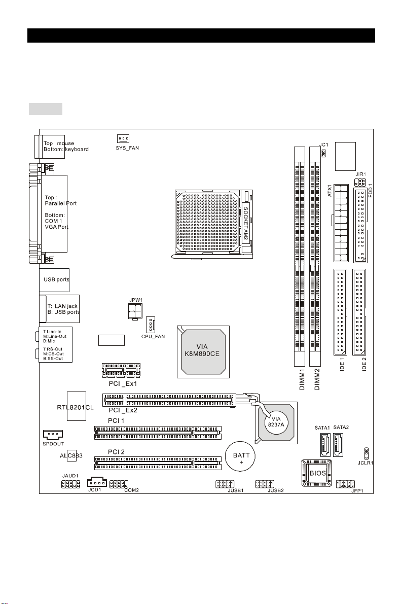
Layout
1
Page 8

Specifications
CPU
l Supports Socket-940 for AMD Athlon 64 / Athlon 64 X2 / Sempron / AM2 processor
(For the latest information about CPU, please visit http://www.msi.com.tw/program/
products/mainboard/mbd/pro_mbd_cpu_support.php )
Chipset
l Northbridge: VIA® K8M890
l Southbridge: VIA® VT8237A
Main Memory
l Dual channel memory architecture ( DIMM1 must be first installed)
l 2 x 240-pin DIMM slots, support DDRII 400/533/667/800 memory modules.
(For the updated supporting memory modules, please visit http://www.msi.com.tw/
program/products/mainboard/mbd/pro_mbd_trp_list.php )
Slots
l One PCI-E x16 Slot
l One PCI-E x1 Slot
l Two PCI Slots (32-bit v2.3 Master PCI bus)
On-Board Peripherals
l External:
- 1 x PS/2 mouse connector
- 1 x PS/2 keyboard connector
- 1 x Parallel port
- 1 x COM port
- 1 x VGA port
- 4 x USB connectors
- 1 x RJ-45 connector
- 1 x Audio jack
l Internal:
- 1 x Intel/MSI standard Front Panel Pinheader
- 2 x Front USB pinheader (4 ports)
- 1 x COM pinheader
- 1 x CPU Fan connector
- 1 x System Fan connector
- 1 x Power Fan connector (Optional)
- 1 x Clear CMOS connector
- 1 x Chassis Intrusion Switch connector
- 1 x Intel® Front Audio pinheader
- 2 x IDE(ATA133) connectors
- 1 x Floppy connector
- 1 x CD-in connector
- 2 x SATA connectors
2
Page 9

Audio
l 8-channel audio codec Realtek ALC883.
- Compliance with AC97 v2.3 Spec.
- Meet PC2001 audio performance requirement.
On-Board LAN
l Realtek 8201CL
- Integrated Fast Ethernet MAC and PHY in one chip.
- Supports 10Mb/s, 100Mb/s.
- Compliance with PCI 2.2.
- Supports ACPI Power Management
BIOS
l Award(LPC) Flash ROM
Dimension
l Micro-ATX Form Factor: 24.4 cm (L) x 22.4 cm (W)
Mounting
l 6 mounting holes
3
Page 10
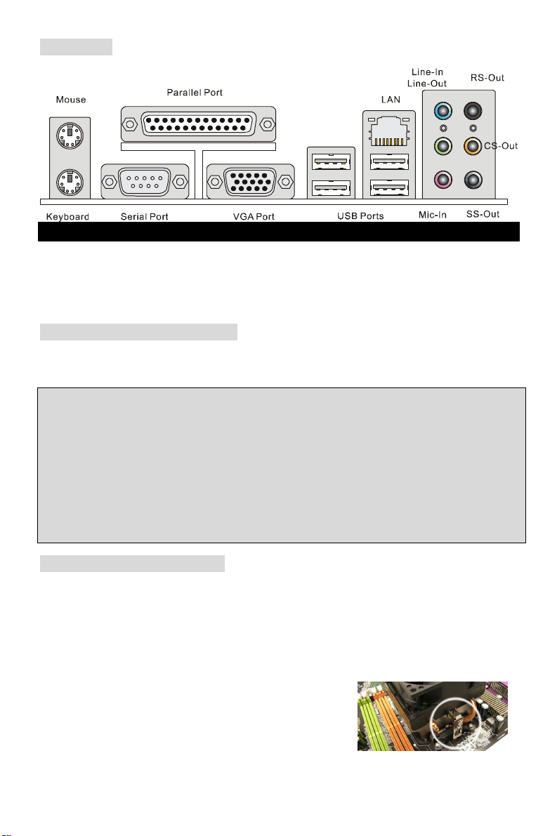
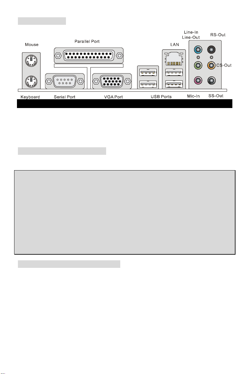
Rear Panel
The rear panel provides the following connectors:
Hardware Setup
This chapter tells you how to install the CPU, memory modules, and expansion cards, as well as
how to setup the jumpers on the mainboard. It also provides the instructions on connecting the
peripheral devices, such as the mouse, keyboard, etc. While doing the installation, be careful in
holding the components and follow the installation procedures.
Central Processing Unit: CPU
The mainboard supports AMD® Athlon64 X2/ Athlon64 & Athlon FX processors. The mainboard
uses a CPU socket called Socket AM2(940-pin) for easy CPU installation.
MSI Reminds You...
Overheating
Overheating will seriously damage the CPU and system, always make sure the cooling fan can
work properly to protect the CPU from overheating.
Overclocking
This motherboard is designed to support overclocking. However, please make sure your
components are able to tolerate such abnormal setting, while doing overclocking. Any attempt to
operate beyond product specifications is not recommended. We do not guarantee the damages
or risks caused by inadequate operation or beyond product specifications.
CPU and Cooler Installation
When you are installing the CPU, make sure the CPU has a cooler attached on the top to prevent
overheating. If you do not have the cooler, contact your dealer to purchase and install them
before turning on the computer. Meanwhile, do not forget to apply some silicon heat transfer
compound on CPU before installing the cooler for better heat dispersion.
Follow the steps below to install the CPU & cooler correctly. Wrong installation will cause the
damage of your CPU & mainboard.
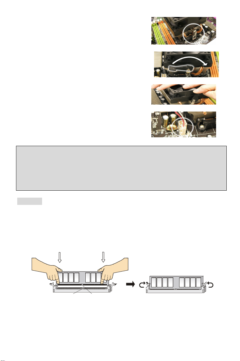
1. Position the cooling set onto the retention mechanism.
Hook one end of the clip to hook first.
4
Page 11
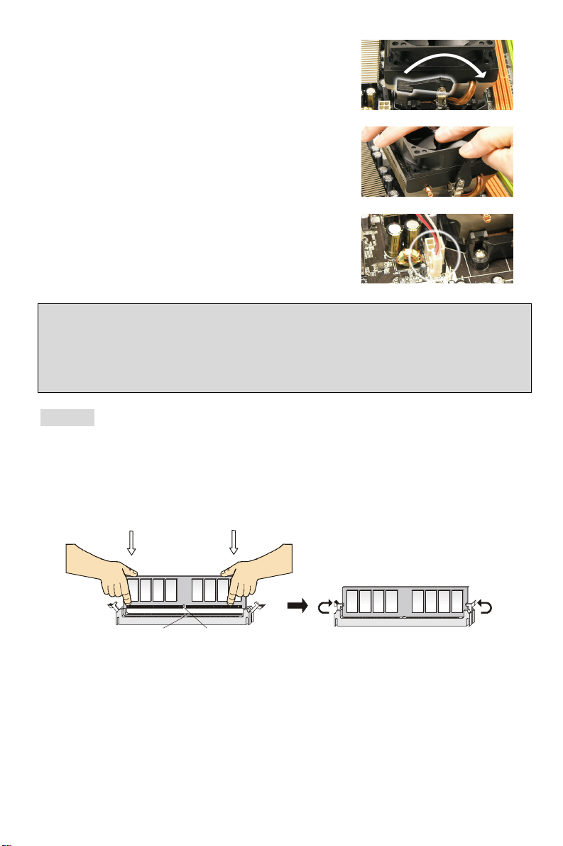
2. Then press down the other end of the clip to fasten the
Notch
Volt
cooling set on the top of the retention mechanism.
Locate the Fix Lever and lift up it.
3. Fasten down the lever.
4. Attach the CPU Fan cable to the CPU fan connector on
the mainboard.
MSI Reminds You...
1. Confirm if your CPU cooler is firmly installed before turning on your system.
2. Check the information in PC Health Status of H/W Monitor in BIOS for the CPU temperature.
3. Please note that the mating/unmating durability of the CPU is 20 cycles. Therefore we suggest
you do not plug/unplug the CPU too often.
Memory
The mainboard provides two 240-pin unbuffered DDR II 400 / 533 / 667 / 800 DIMM slots, and
supports the memory size up to 2GB. To operate properly, at least one memory module must be
installed.
Install at least one memory module on the slots. Memory modules can be installed on the slots in
any order. You can install either single- or double-sided modules to meet your own needs.
Installing DDR II Modules
1. The memory module has only one notch on the center of module. The memory module
will only fit in the right orientation.
2. Insert the memory module vertically into the DIMM slot. Then push it in until the golden
finger on the memory module is deeply inserted in the DIMM slot.
3. The plastic clip at each side of the DIMM slot will automatically close.
5
Page 12
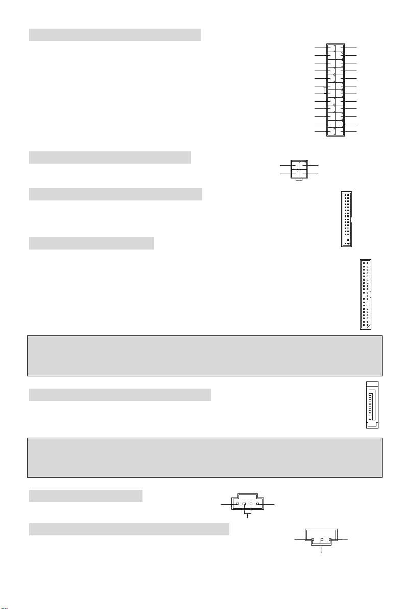
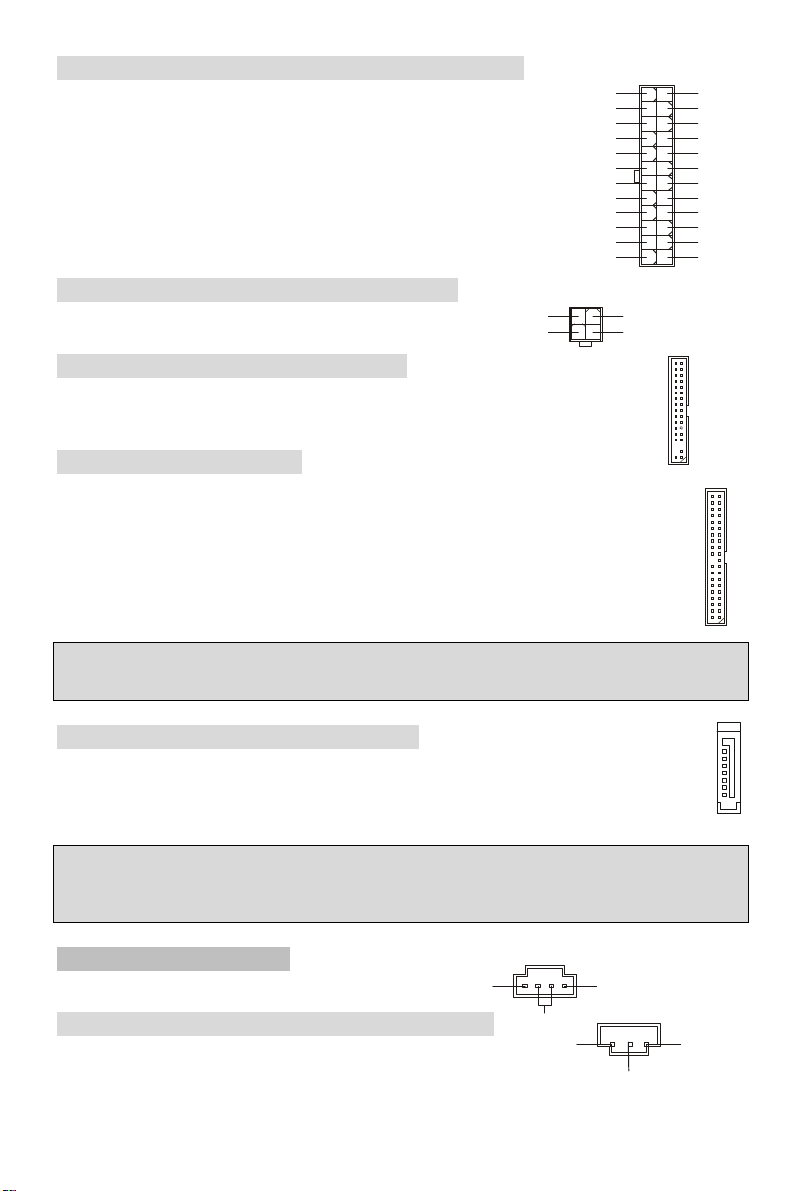
ATX 24-Pin Power Connector: ATX1
L
GND
1
3
4
2
GND
12V
1
12
24
13
+3.3V
+3.3V
PS-ON#
PWR OK
This connector allows you to connect an ATX 24-pin power supply. To
connect the ATX 24-pin power supply, make sure the plug of the power
supply is inserted in the proper orientation and the pins are aligned.
Then push down the power supply firmly into the connector.
You may use the 20-pin ATX power supply as you like. If you’d like to
use the 20-pin ATX power supply, please plug your power supply along
with pin 1 & pin 13. There is also a foolproof design on pin 11, 12, 23 &
24 to avoid wrong installation.
+3.3V
-12V
GND GND
GND GND
GND +5V
GND GND
Res
+5V 5VSB
+5V +12V
+5V +12V
GND NC
+5V
ATX 12V Power Connector: JPW1
This 12V power connector is used to provide power to the CPU.
GND
12V
Floppy Disk Drive Connector: FDD1
The mainboard provides a standard floppy disk drive connector that supports 360K,
720K, 1.2M, 1.44M and 2.88M floppy disk types.
IDE Connector: IDE1/IDE2
The mainboard has dual Ultra DMA 66/100/133 controller that provides PIO mode 0~4,
Bus Master, and Ultra DMA 66/100/133 function. You can connect up to four hard disk
drives, CD-ROM, 120MB Floppy and other devices.
The first hard drive should always be connected to IDE1. IDE1 can connect a Master and
a Slave drive. You must configure second hard drive to Slave mode by setting the jumper
accordingly.
MSI Reminds You...
If you install two hard disks on one cable, you must configure the second drive to Slave mode by
setting its jumper. Refer to the hard disk documentation supplied by hard disk vendors for jumper
setting instructions.
Serial ATA Connectors: SATA1/SATA2
The mainboard provides two high-speed Serial ATA interface ports. These ports support
Serial ATA data rates of 150MB/s and are fully compliant with Serial ATA 1.0 specification.
Each Serial ATA connector can connect to 1 hard disk device.
MSI Reminds You...
Please do not fold the serial ATA cable in a 90-degree angle, which will cause the loss of data
during transmission.
CD-In Connector: JCD1
The connector is for CD-ROM audio connector.
SPDIF-Out Connector: SPDOUT(optional)
This connector is used to connect SPDIF (Sony & Philips Digital
Interconnect Format) interface for digital audio transmission.
6
R
GND
SPDIF
VCC
7
1
Page 13
+12V
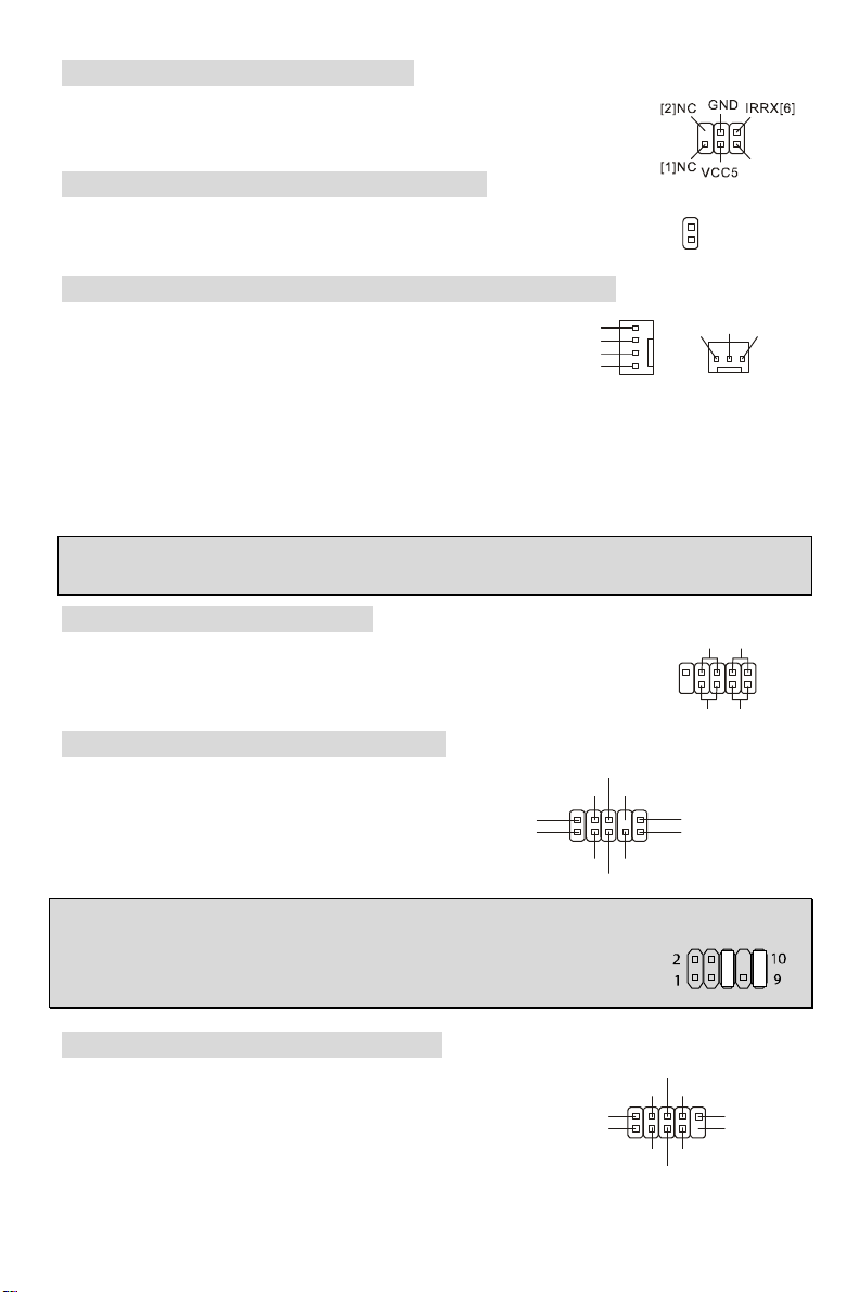
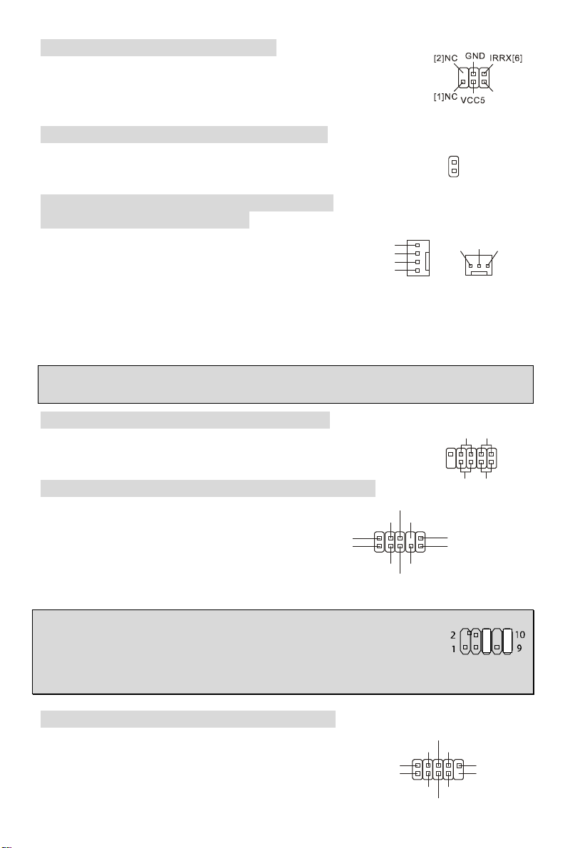
IrDA Infrared Module Header: JIR1
AUD_RET_R
AUD_RET_L(10)
AUD_FPOUT_L(9)
USB0+
USB1+
USB0C(10)
JFP1
Power
HDD
Reset
192
CINTRU
IRTX[5]
The connector allows you to connect to IrDA Infrared module and is
compliant with Intel Front Panel I/O Connectivity Design Guide. You must
configure the setting through the BIOS setup to use the IR function.
Chassis Intrusion Switch Connector: JC1
This connector is connected to a 2-pin chassis switch. JC1 is compliant with
Intel® Front Panel I/O Connectivity Design Guide.
GND
2
1
Fan Power Connectors: CPU_FAN/SYS_FAN(optional)
The 4-pin CPU_FAN (processor fan), 3-pin SYS_FAN
(system fan) support system cooling fan with +12V.
CPUFAN can support three- or four-pin head connector.
When connecting the wire to the connectors, always take
note that the red wire is the positive and should be
connected to the +12V, the black wire is Ground and should be connected to GND. If the
mainboard has a System Hardware Monitor chipset on-board, you must use a specially designed
fan with speed sensor to take advantage of the CPU fan control.
MSI Reminds You...
Always consult the vendors for the proper CPU cooling fan.
ControlControl
SENSOR
+12V
GND
GND
CPU_FAN SYS_FAN
NC
Front Panel Connectors: JFP1
Key
HP_ON
10
Switch
Power
Switch
The mainboard provides two front panel connectors for electrical connection
to the front panel switches and LEDs. JFP1 is compliant with Intel® Front
Panel I/O Connectivity Design Guide.
Front Panel Audio Connector: JAUD1
The front panel audio connector allows you to
connect to the front panel audio and is
compliant with Intel® Front Panel I/O
Connectivity Design Guide.
(2)AUD_GND
(1)AUD_MIC
MSI Reminds You...
If you do not want to connect to the front audio header, pins 5 & 6, 9 & 10 have
to be jumpered in order to have signal output directed to the rear audio ports.
Otherwise, the Line-Out connector on the back panel will not function.
AUD_VCC
AUD_MIC_BIAS
AUD_FPOUT_R
Front USB Connector: JUSB1/JUSB2
The mainboard provides two standard USB 2.0 pin headers
JUSB1&JUSB2. USB2.0 technology increases data transfer
rate up to a maximum throughput of 480Mbps, which is 40
times faster than USB 1.1, and is ideal for connecting
high-speed USB interface peripherals such as USB HDD,
USB1- GND
(2)VCC
(1)VCC Key(9)
GND
USB0-
7
LED
LED
Page 14
digital cameras, MP3 players, printers, modems and the like.
MSI Reminds You...
Please note that the pins of VCC & GND must be connected correctly or it may cause some
damage
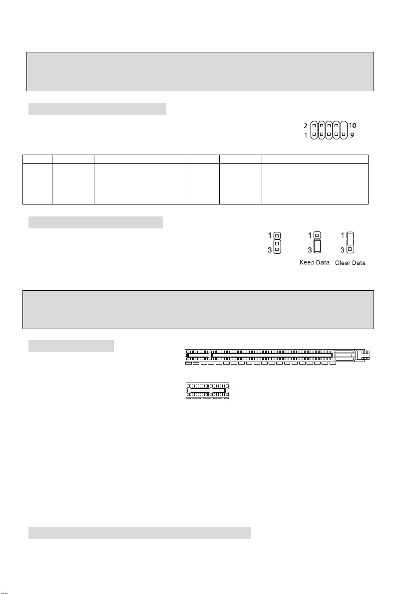
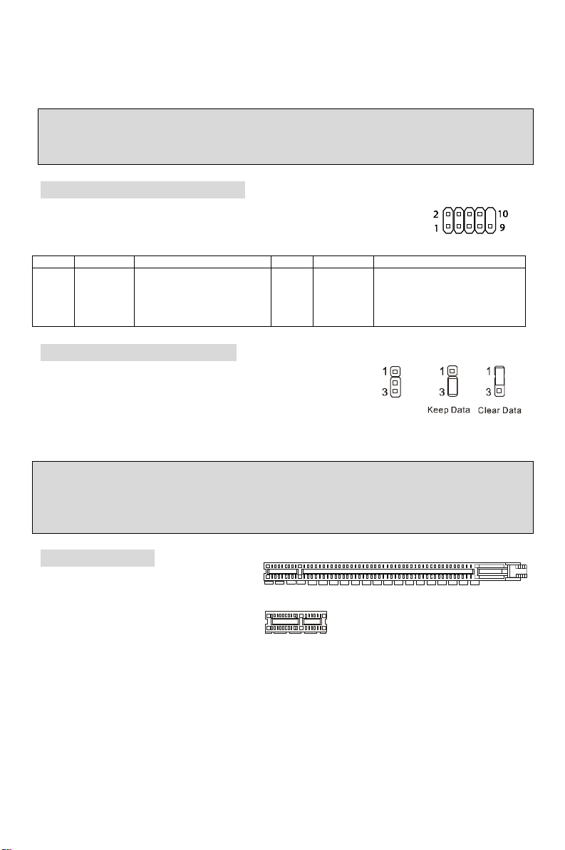
Serial Port Connector: COM2
The mainboard offers one 9-pin male DIN connector COM 1 (on the rear
panel), and one optional serial port JCOM1. Both are 16550A high speed
communication ports that send/receive 16 bytes FIFOs. You can attach a
serial mouse or other serial device directly to them.
PIN SIGNAL
1
DCD
3
SOUT
5
GND
7
RTS
9
DESCRIPTION PIN
Data Carry Detect
Receive Data Transmit
Data
Request To Send Ring
RI
Indicate
10
SIGNAL
2
4
6
8
SIN
DTR
DSR
CTS
DESCRIPTION
Serial in or receive data
Serial out or transmit data
Data Set Ready
Clear To Send
X
X
Clear CMOS Jumper: JCLR1
There is a CMOS RAM on board that has a power supply from
external battery to keep the data of system configuration. With the
CMOS RAM, the system can automatically boot OS every time it
is turned on. If you want to clear the system configuration, use the
JCLR1 (Clear CMOS Jumper) to clear data. Follow the instructions in the image to clear the data.
MSI Reminds You...
You can clear CMOS by shorting 1-2 pin while the system is off. Then return to 2-3 pin position.
Avoid clearing the CMOS while the system is on, which will damage the mainboard.
PCI Express Slots
The PCI Express slot, as a
high-bandwidth, low pin count, serial,
interconnect technology, support Intel
PCI Express X16 Slot
highest performance desktop platforms
utilizing the Intel Pentium 4 processor
with HT Technology with these platform
benefits. You can insert the expansion
PCI Express X1 Slot
cards to meet your needs. When adding
or removing expansion cards, make sure that you unplug the power supply first. PCI Express
architecture provides a high performance I/O infrastructure for Desktop Platforms with transfer
rates starting at 2.5 Giga transfers per second over a PCI Express x1 lane for Gigabit Ethernet,
TV Tuners, 1394 controllers, and general purpose I/O. Also, desktop platforms with PCI Express
Architecture will be designed to deliver highest performance in video, graphics, multimedia and
other sophisticated applications. Moreover, PCI Express architecture provides a high
performance graphics infrastructure for Desktop Platforms doubling the capability of existing
AGP8x designs with transfer rates of 4.0 GB/s over a PCI Express x16 lane for graphics
controllers, while PCI Express x1 supports transfer rate of 250 MB/s.
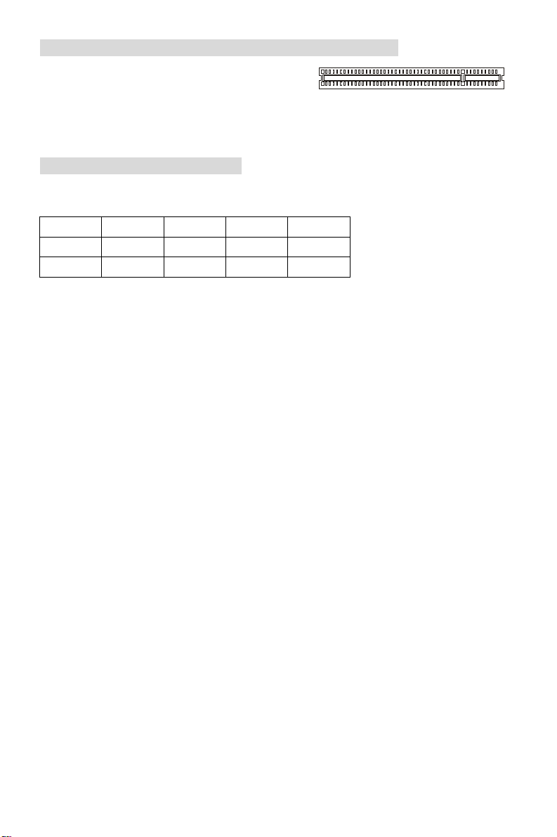
PCI (Peripheral Component Interconnect) Slots
8
Page 15
The PCI slots allow you to insert the expansion cards
to meet your needs. When adding or removing
expansion cards, make sure that you unplug the
power supply first. Meanwhile, read the documentation for the expansion card to make any
necessary hardware or software settings for the expansion card, such as jumpers, switches or
BIOS configuration.
PCI Interrupt Request Routing
The IRQ, abbreviation of interrupt request line and pronounced I-R-Q, are hardware lines over
which devices can send interrupt signals to the microprocessor. The PCI IRQ pins are typically
connected to the PCI bus INT A# ~ INT D# pins as follows:
Order1 Order2 Order3 Order4
PCI Slot 1 INT B# INT C# INT D# INT A#
PCI Slot 2 INT C# INT D# INT A# INT B#
9
Page 16

BIOS Setup
Power on the computer and the system will start POST (Power On Self Test) process. When the
message below appears on the screen, press <DEL> key to enter Setup.
DEL: Setup
If the message disappears before you respond and you still wish to enter Setup, restart the
system by turning it OFF and On or pressing the RESET button. You may also restart the system
by simultaneously pressing <Ctrl>, <Alt>, and <Delete> keys.
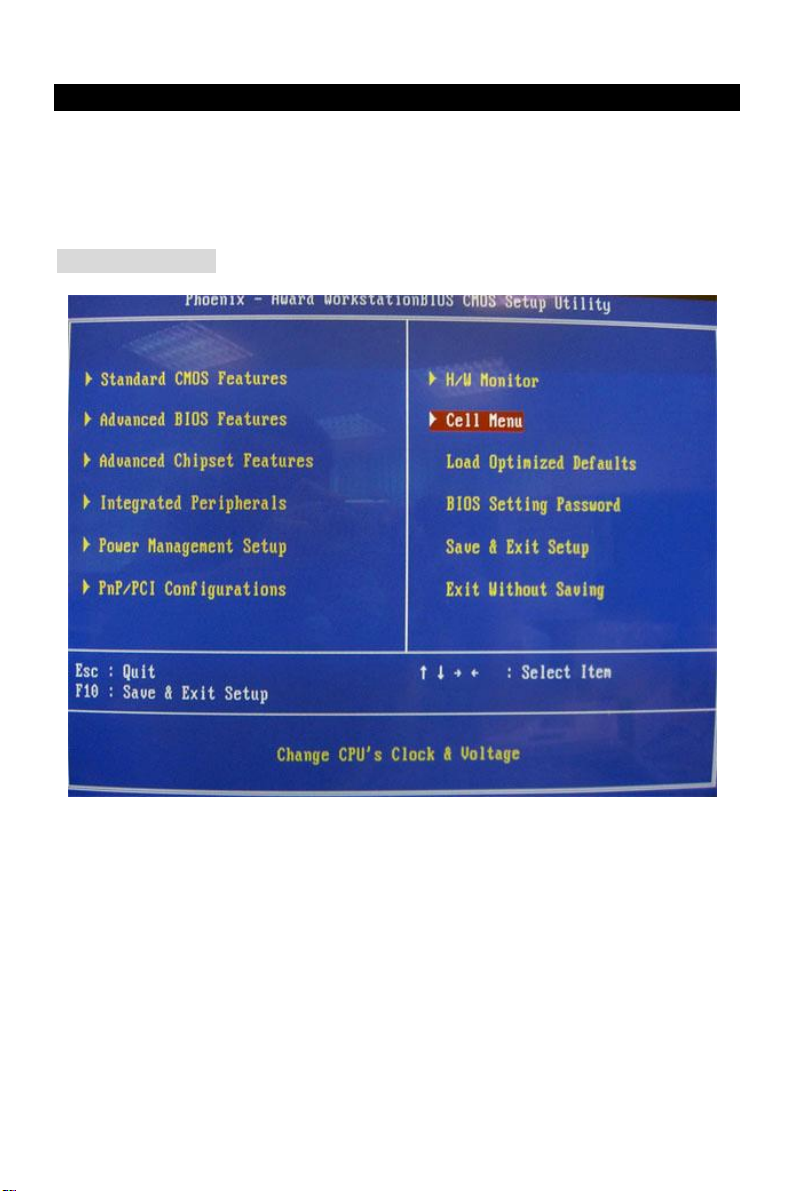
Main Page
Standard CMOS Features
Use this menu for basic system configurations, such as time, date etc.
Advanced BIOS Features
Use this menu to setup the items of Award special enhanced features.
Advanced Chipset Features
Use this menu to change the values in the chipset registers and optimize your system
performance.
Integrated Peripherals
Use this menu to specify your settings for integrated peripherals.
Power Management Setup
Use this menu to specify your settings for power management.
10
Page 17
PnP/PCI Configuration
This entry appears if your system supports PnP/PCI.
H/W Monitor
This entry shows information of your CPU, fan and overall system status.
Cell Menu
Use this menu to specify your settings for CPU/AGP frequency/voltage control and overclocking.
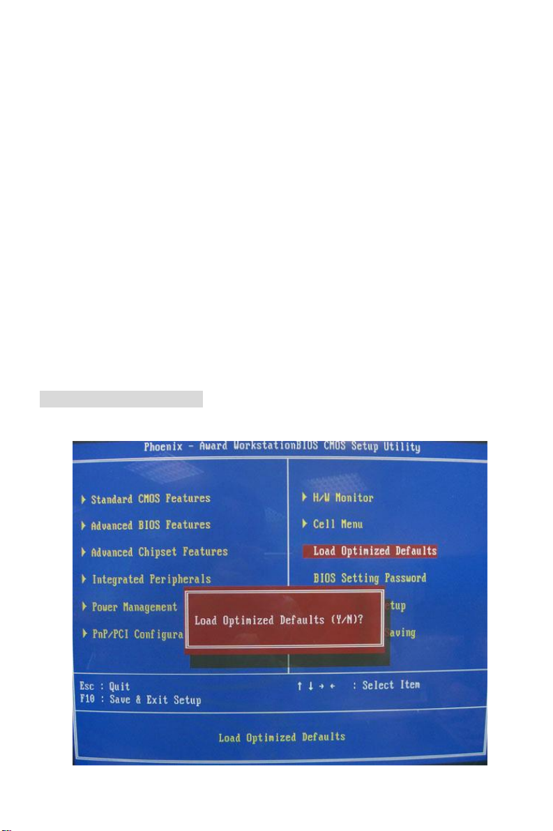
Load Optimized Defaults
Use this menu to load factory default settings into the BIOS for stable system performance
operations.
BIOS Setting Password
Use this menu to set password.
Save & Exit Setup
Save changes to CMOS and exit setup.
Exit Without Saving
Abandon all changes and exit setup.
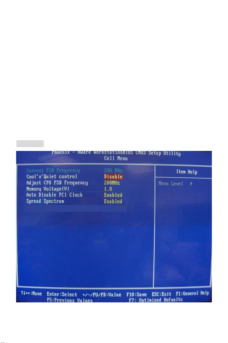
Cell Menu
11
Page 18
Current FSB Frequency
It shows the current clock frequency of the front side bus. (read only)
Adjust CPU FSB Frequency
This setting allows you to select the clock frequency of CPU FSB.
Memory Voltage
Adjusting the DDR voltage can increase the DDR speed. Any changes made to this setting
may cause a stability issue, so changing the DDR voltage for long-term purpose is NOT
recommended.
Auto Disable PCI Clock
This item is used to auto detect the PCI slots. When set to [Enabled], the system will remove
(turn off) clocks from empty PCI slots to minimize the electromagnetic interference (EMI).
Spread Spectrum
When the motherboard’s clock generator pulses, the extreme values (spikes) of the pulses
create EMI (Electromagnetic Interference). The Spread Spectrum function reduces the EMI
generated by modulating the pulses so that the spikes of the pulses are reduced to flatter curves.
If you do not have any EMI problem, leave the setting at [Disabled] for optimal system stability
and performance. But if you are plagued by EMI, select the desired range for EMI reduction.
Remember to disable Spread Spectrum function if you are overclocking, because even a slight
jitter can introduce a temporary boost in clock speed which may just cause your overclocked
processor to lock up.
Load Optimized Defaults
You can load the default values provided by the mainboard manufacturer for the stable
performance.
12
Page 19
Introduction
Félicitation vous venez d’acheter les séries K9VGM –V (MS-7253 v1.x), une carte mère
excellente de MSI. les séries K9VGM -V sont basées sur les chipsets on VIA® K8M890 & VIA®
VT8237A pour obtenir un système performant. Destiné aux processeurs avancés AMD®
Sempron / Athlon 64 / Athlon 64 X2 pour le Socket AM2. Les séries K9VGM -V offrent de hautes
perforrmances tant aux particuliers qu’aux professionnels.
Layout
13
Page 20

Spécificités
CPU
l Supporte les processeurs Socket-940 pour Athlon 64 / Athlon 64 X2 / Sempron / AM2
(Pour plus d’informations, veuillez visiter http://www.msi.com.tw/program/
products/mainboard/mbd/pro_mbd_cpu_support.php )
Chipset
l Pont Nord: VIA® K8M890
l Pont Sud: VIA® VT8237A
Mémoire Principale
l Architecture de mémoire ave canal double (DIMM1 doit d’abord être installé)
l Slot DIMM (2 x 240-pin), supporte les modules de mémoire DDRII 400/533/667/800.
(Pour une mise à jour sur les modèles de mémoires supportés, veuillez visiter
http://www.msi.com.tw/program/products/mainboard/mbd/pro_mbd_trp_list.php )
Slots
l Un slot PCI-E x16
l Un slot PCI-E x1
l Deux slots PCI (32-bit v2.3 Master PCI bus)
Périphériques intégrés
l Externe:
- 1 x PS/2 connecteur souris
- 1 x PS/2 connecteur clavier
- 1 x port Parallèle
- 1 x port COM
- 1 x port VGA
- 4 x connecteurs USB
- 1 x connecteur RJ-45
- 1 x Audio jack
l Interne:
- 1 x connecteur Front Panneau du standard d’ Intel/MSI
- 2 x connecteurs Front USB (4 ports)
- 1 x connecteur COM
- 1 x connecteur ventilateur du CPU
- 1 x connecteur ventilateur du système
- 1 x connecteur ventilateur de l’alimentation (Optionnel)
- 1 x connecteur Clear CMOS
- 1 x connecteur Switch Chassis Intrusion
- 1 x connecteur Intel® Front Audio
- 2 x connecteurs IDE(ATA133)
- 1 x connecteur Disquette
- 1 x connecteur CD-in
- 2 x connecteurs SATA
14
Page 21

Audio
l 8-canal audio codec Realtek ALC883.
- Compatible avec les Spec. AC97 v2.3
- Compatible avec les performances audio PC2001
LAN Intégré
l Realtek 8201CL
- Fast Ethernet MAC et PHY intégrés dans un chip.
- Supporte 10Mb/s, 100Mb/s.
- Compatible avec PCI 2.2.
- Supporte l’ACPI Power Management
BIOS
l Flash ROM Award(LPC)
Dimension
l Format Facteur Micro-ATX: 24.4 cm (L) x 22.4 cm (W)
Montage
l 6 trous de montages
15
Page 22
Panneau Arrière
Le panneau arrière procure les connecteurs suivants:
Installation Matériel
Ce chapitre vous donne des indications sur l’installation du CPU, des modules de mémoire, les
cartes d’extension, ainsi que sur la configuration des cavaliers de la carte mère. Vous
retrouverez aussi des instructions pour la connexion de périphériques(souris,clavier...)
Lors de l’installation, veuillez vous prémunir contre l’électricité statique et veuilez suivre les
procédures d’installation afin de mettre en place correctement les différents composants.
Central Processing Unit: CPU
La carte mère supporte les processeurs AMD® Athlon64 X2/ Athlon64 & Athlon FX. La carte
utilise un socket appelé Socket AM2(940-pin) pour installer plus simplement le CPU.
MSI vous Rappelle...
Surchauffe
Une surchauffe peut sérieusement endommager le CPU et le système, assurez vous toujours
que le système de reffroidissement fonctionne correctement pour protéger le CPU d’une
surchauffe.
Overclocking
Cette carte mère a été créee pour supporter l’overclocking. veuillez s'assurer que vos
composants peuvent tolérer un tel arrangement anormal avant d’overclocker le système. Tout
essais au delàdes spécifications des produits n'est recommandée. Nous ne garantissons pas les
dommages ou les risques causés par une opération insatisfaisante ou au delà des spécifications
du produit.
Installer le CPU et le Refroidisseur
Quand vous installez votre CPU, assurez vous que le CPU possède un système de
refroidissement pour prévenir les surchauffes. Si vous ne possédez pas de système de
refroidissement, contactez votre revendeur pour vous en procurer un et installez le avant
d’allumer l’ordinateur. N’oubliez pas d’utiliser des composants en silicium de transfert de chaleur
avant d’installer le refroidissement pour une meilleure dissipation de la chaleur.
Suivez les mesures suivantes pour installer correctement le système refroidissement & le CPU,
sinon, une mauvaise installation risque d’endommager votre CPU et la carte mère.
16
Page 23
1. Positionnez le système de refroidissement sur le
Notch
Volt
mécanisme d’attache. Accrochez une extrémité du clip
avant de tout accrocher.
2. Appuyez alors l'autre extrémité de l'agrafe pour attacher
l'ensemble de refroidissement au sommet du
mécanisme de rétention. Localisez le levier de fixation
et soulevez-le vers le haut.
3. Fixez le levier vers le bas.
4. Attachez le câble de ventilateur de CPU au connecteur
sur la carte.
MSI Vous Rappelle...
1. Vérifier la connexion du ventilateur de CPU avant de démarrer le PC.
2. Vérifier les informations dans le BIOS PC Health Status du H/W Monitor au sujet de la
température du CPU.
3. A noter que la mise en place du CPU est prévue pour une vingtaine de connexion, cependant
il n’est pas recommandé d’installer/retirer le CPU trop souvent.
Mémoire
La carte mère possède deux slots unbuffered DIMM DDR II 400 / 533 / 667 / 800(240-pin), et
supporte jusqu’à 2GB de mémoire. Vous devez au moins installer un module de DIMM. Il faut au
moins installer un module DIMM sur les slots. L’installation des modules de mémoires n’a pas de
sens particulier. Votre installation soit des modules simples ou doubles faces si vous en avez
besoin.
Installer les Modeles DDRII
1. Le slot DDR II ne possède qu’une encohe en son centre. Ainsi il n’est possible de monter
le module que dans un seul sens..
2. Insérez verticalement le module de mémoire dans le slot DIMM. Puis appuyez dessus.
3. Le clip en plastique situé de chaque côté du module va se fermer automatiquement.
17
Page 24
Connecteur d’alimentation ATX 24 broches: ATX1
L
GND
1
3
4
2
GND
12V
1
12
24
13
+3.3V
+3.3V
PS-ON#
PWR OK
Ce connecteur vous permet de connecter l’alimentation ATX 24-pin.
Pour cela assurez-vous que la prise d’alimentation est bien positionné
dans le bon sens et que les goupilles sont alignées. Enfoncer alors la
prise dans le connecteur.
Vous pouvez aussi utiliser une alimentation 20-pin, veuillez brancher
votre alimentation d'énergie avec le pin1 et le pin 13. Il y a également
une conception indéréglable sur le pin 11, 12. 23 et 24 pour éviter
l'installation fausse.
+3.3V
-12V
GND GND
GND GND
GND +5V
GND GND
Res
+5V 5VSB
+5V +12V
+5V +12V
GND NC
Connecteur d’alimentation ATX 12V: JPW1
Le connecteur d’alimentation 12V est utilisé pour alimenter le CPU.
GND
12V
Connecteur Floppy Disk Drive: FDD1
La carte comporte un connecteur standard pour un lecteur de disquette qui supporte
les formats 360K, 720K, 1.2M, 1.44M et 2.88M.
IDE Connector: IDE1/IDE2
La carte mère possède un contrôleur double Ultra DMA 66/100/133 qui procurent les
fonctions PIO mode 0~4, Bus Master, et Ultra DMA66/100/133. Vous pouvez connecter
jusqu’à 4 périphériques (disques durs, CD-ROM, 120MB Disquette).
Le premier disque dur doit être connecté sur l’IDE1. L’IDE1 peut recevoir un périphérique
Maître et un Esclave. Vous devez configurer le second disque en mode Esclave et ce à
l’aide du cavalier situé à l’arrière.
MSI Vous Rappelle...
Si vous voulez installer deux disques durs, vous devez configurer le second en Esclave en
configurant le cavalier. Se référer à la documentation du disque dur pour les instructions.
Connecteurs Série ATA: SATA1/SATA2
Cette carte mère fournit deux ports d’une interface de Sé rie ATA à grande vitesse. ces ports
supportent un taux des données de Série ATA de 150MB/ et ils conforment entièremen
avec caractéristique de Série ATA 1.0. Chaque connecteur d'ATA peut se relier à 1 dispositif
de disque dur.
MSI Vous Rappelle…
Veuillez ne pas tordre le caâble Série ATA à degré de 90. Cela pourraît l’endommager et
entraîner la perte de données lors des phases de transfert de ces dernières.
Connecteur CD-In: JCD1
Ce connecteur est utilisé pour le connecteur CD-ROM audio .
Connecteur Sortie SPDIF: SPDOUT(optionnel)
Ce connecteur est utilisé pour connecter l’interface SPDIF (Sony &
Philips Digital Interconnect Format) afin d’une transmission audio
digital .
18
R
GND
SPDIF
VCC
+5V
7
1
Page 25
+12V
En-tête de Module Infrarouge: JIR1
AUD_RET_R
AUD_RET_L(10)
AUD_FPOUT_L(9)
USB0+
USB1+
USB0C(10)
JFP1
Power
HDD
Reset
192
CINTRU
IRTX[5]
Le connecteur vous permet de connecter le modeule infrarouge IrDA, et
JIR1 est compatible avec Intel Front Panel I/O Connectivity Design Guide.
Vous devez configurer la connexion par l'installation du BIOS pour utiliser la
fonction IR.
Connecteur Chassis Intrusion Switch: JC1
Ce connecteur est relié à un chassis switch ( 2-pin). JC1 est compatible avec
l’Intel® Front Panel I/O Connectivity Design Guide..
GND
2
1
Connecteurs d’alimentation du ventilateur:
CPU_FAN/SYS_FAN(optionnel)
Le 4 broches CPU_FAN ( processeur du ventilateur) et le
3 broches SYS-FAN (système du ventilateur ) supportent
le +12V. CPUFAN peut supporter 3 ou 4 broches. Lors
de la connexion du câble, assurez-vous que le fil rouge
soit connecté au +12V et le fil noir connecté au “GND“. Si
la carte mère possède un système de gestion intégré, vous devez utiliser un ventilateur ayant
ces caractéristiques si vous voulez contrôler le ventilateur du CPU.
MSI Vous rappelle...
Il faut toujours consulter votre revendeur au sujet du ventilateur.
ControlControl
SENSOR
+12V
GND
GND
CPU_FAN SYS_FAN
NC
Connecteurs Panneau de la façade: JFP1
Key
HP_ON
10
Switch
Power
Switch
La carte mère procure 2 connecteurs pour les branchements électriques.
JFP1 est compatible avec Intel Front Panel I/O Connectivity Design Guide.
Connecteurs Audio Panneau de la façade: JAUD1
Ce connecteur vous permet de connecter le
panneau audio en façade et il est compatible
avec Intel® Front Panel I/O Connectivity Design
Guide.
(2)AUD_GND
(1)AUD_MIC
AUD_VCC
AUD_MIC_BIAS
AUD_FPOUT_R
MSI Vous rappelle...
Si vous ne voulez pas connecter l’audio en façade à l’aide des broches
5 & 6, 9 & 10 doivent être recouvertes par un cavalier pour envoyer le
signalvers les ports audio à l’arrière. Autrement le connecteur Line-Out à l’arrière ne
fonctionnera pas.
Connecteurs USB en façade: JUSB1/JUSB2
La carte mère procure deux connecteurs au standard USB
2.0 JUSB1 & JUSB2. La technologie USB 2.0 accroît le taux
du transfert jusqu’à 480Mbps, qui est 40 fois plus rapide que l’
19
USB1- GND
(2)VCC
(1)VCC Key(9)
GND
USB0-
LED
LED
Page 26
USB 1.1. Idéal pour relier les périphériques à grande vitesse utilisant l’interface USB tels que les
disques externe USB, appareils-photo numériques, lecteurs MP3, imprimantes, modems...
MSI Vous Rappelle...
A noter que les broches VCC et GND doivent être correctement connecter afin d’éviter tout
endommagement.
Connecteur Série Port : COM2
La carte mère offre un connecteur COM1 9-pin male DIN (sur le panneau
arrière), et un port de série optionnel JCOM1. Tous deux sont des ports de
communication haute vitesse 16550A qui envoie/reçoit 16 bytes FIFOs.
Vous pouvez y attaché une souris de série ou autre composants de série directement.
PIN SIGNAL
1
DCD
3
SOUT
5
GND
7
RTS
9
DESCRIPTION PIN
Data Carry Detect
Receive Data Transmit
Data
Request To Send Ring
RI
Indicate
10
SIGNAL
2
4
6
8
SIN
DTR
DSR
CTS
DESCRIPTION
Serial in or receive data
Serial out or transmit data
Data Set Ready
Clear To Send
X
X
Cavalier Clear CMOS: JCLR1
La CMOS RAM intégré reçoit une alimentation d’une batterie
externe qui permet de garder les données de configuration du
système. Avec la CMOS RAM, le système peut automatiquement
booter avec les paramètres personnalisés du BIOS à chaque fois
que le PC est allumé. Si vous voulez effacer la configuration du système, utilisez le JCLR1
(Cavalier Clear CMOS) pour effacer les données. Suivez les instructions de l’image pour effacer
les données.
MSI Vous Rappelle...
Vous pouvez effacer les données en positionnant le cavalier sur les broches 1-2 quand le PC
n’est pas allumé. Puis il faut remettre le cavalier en position 2-3. Ne surtout pas effacer les
données lorsque le PC est en fonction, cela endommagera la carte mère.
PCI Express Slot
Les slots PCI Express 16x possèdent une
large bande passante, supportent les
plateformes desktop Intel haute
PCI Express X16 Slot
performances utilisant le processeur Intel
Pentium 4 avec la Technologie HT.
L’architecture PCI Express procure une
infrastructure I/O haute performance
PCI Express X1 Slot
architecture pour plateformes Desktop
avec un taux de transfert débutant à 2.5 Giga/s sur un PCI Express x1 pour Gigabit Ethernet, TV
Tuners, contrôleurs 1394, et autre usage I/O. Les plateformes Desktop avec architecture PCI
Express ont été conçu pour délivrer de hautes performances en vidéo, graphisme, multimédia et
autres applications sophistiquées.
De plus, l’architecture PCI Express procure une infrastructure performante pour le graphique et
double la capacité de l’AGP 8X avec un taux de transfert de données de 4.0 GB/s sur un PCI
Express x16 pour contrôleur graphique alors que le PCI Express x 1 supporte un taux de
transfert de 250 MB/s.
20
Page 27
Slots PCI ((Interconnexion Composante Périphérique)
Les slots PCI vous permettent d’insérer des cartes
d’extension selon vos besoins. Lorsque vous ajoutez
ou enlever une carte d’extension, assurez-vous que
le PC n’est pas relié au secteur. Lisez la documentation pour que la carte d'extension fasse tout
le nécessaires (matériel et de logiciel) pour cette carte, comme des pullovers, commutateurs ou
configuration de BIOS.
PCI Interrupt Request Routing
IRQ est l’ abréviation de “interrupt request line”. Les IRQ sont des signaux émis par des matériels.
Les PCI IRQ sont connectés généralement aux broches PCI bus INT A# ~ INT D# comme
suivant:
Order1 Order2 Order3 Order4
PCI Slot 1 INT B# INT C# INT D# INT A#
PCI Slot 2 INT C# INT D# INT A# INT B#
21
Page 28
Setup du BIOS
Lorsque le PC démarre le processus de POST (Power On Self Test) se met en route. Quand le
message ci-dessous apparaît, appuyer sur <DEL> pour accéder au Setup.
DEL: Setup
Si le message disparaît avant que n’ayez appuyé sur la touche, redémarrez le PC à l’aide du
bouton RESET. Vous pouvez aussi redémarrer en utilisant la combinaison de touches <Ctrl>,
<Alt>, et <Delete>.
Page Principale
Standard CMOS Features
Cette fonction permet le paramétrage des éléments standard du BIOS tels que l’heure, etc.
Advanced BIOS Features
Cette fonction permet de paramétrer des éléments avancés du BIOS.
Advanced Chipset Features
Cette option vous permet de paramétrer les éléments relatifs au registre du chipset, permettant
ainsi d’optimiser les performances de votre système.
Integrated Peripherals
Utiliser ce menu pour paramétrer les périphériques intégrés.
Power Management Setup
22
Page 29

Utilisez ce menu pour appliquer vos choix en ce qui concerne le power management.
PNP/PCI Configurations
Apparaît si votre système supporte PNP/PCI.
H/W Monitor
Voir les statuts des CPU, du ventilateur, et de l’alarme du système.
Cell Menu
Utilisez ce menu pour configurer vos paramètres pour le contrôle de la fréquence/voltage.
Load Optimized Defaults
Charge les paramètres optimum du BIOS sans affecter la stabilité du système.
BIOS Setting Password
Utilisez ce menu pour entrer un mot de passe du BIOS
Save & Exit Setup
Les modifications sont enregistrés dans le CMOS avant la sortie du setup.
Exit Without Saving
Les modifications sont abandonnées avant la sortie du setup.
Cell Menu
23
Page 30

Current FSB Frequency
Fréquence d’horloge du FSB. Lecture unique.
Adjust CPU FSB Frequency
Ces articles vous permettent ajuster la Fréquence de CPU FSB.
Memory Voltage
Ajuster le voltage DDR peut augmenter la vitesse de la DDR. Tous changements peuvent
entraîner une instabilité, c’est pourquoi les changements à longs termes ne sont pas
recommandés.
Auto Disable PCI Clock
Cet article est utilisé à l'automobile détectent les slots de PCI. Quand ensemble à [ permis ], le
système enlèvera (éteignez) des horloges des slots vides de PCI pour réduire au minimum
l'interférence électromagnétique (IEM).
Spread Spectrum
Les cartes mères créent des interférences éléctromagnétiques (EMI - Electromagnetic
Interference). La fonction Spread Spectrum réduit ces EMI. Si vous n’avez pas de problème
d’EMI, laissez l’option sur Disabled, ceci vous permet une stabilité du système et des
performances optimales. Dans le cas contraire, choisissez Enabled pour réduire les EMI.
N’oubliez pas de désactiver cette fonction si vous voulez faire de l’overclocking, afin d’éviter tout
problème.
Load Optimized Defaults
Vous pouvez charger les paramètres par défaut procurés par le constructeur de la carte mère
pour une performance stable.
24
Page 31

Einleitung
Danke, dass Sie das K9VGM -V Series (MS-7253 v1.x) Micro-ATX Mainboard gewählt haben.
Das K9VGM -V Series basiert auf dem VIA® K8M890 & VIA® VT8237A Chipsatz und ermöglicht
so ein optimales und effizientes System. Entworfen, um den hochentwickelten AMD® Sempron /
Athlon 64 / Athlon 64 X2 Prozessor aufzunehmen, stellt das Sockel AM2, K9VGM -V Series die
ideale Losung zum Aufbau eines professionellen Hochleistungsdesktopsystems dar.
Layout
25
Page 32

Spezifikationen
CPU
l Unterstützt Sockel-940 für AMD Athlon 64 / Athlon 64 X2 / Sempron / AM2 Prozessor
(Die neuesten Informationen zu unterstützten Prozessoren finden Sie unter
http://www.msi.com.tw/program/products/mainboard/mbd/pro_mbd_cpu_support.php )
Chipsatz
l Northbridge: VIA® K8M890
l Southbridge: VIA® VT8237A
Hauptspeicher
l Zwei- Kanal Speicherarchitektur ( Bestücken Sie immer die DIMM1 zuerst.)
l 2 x 240-Pin DIMM, Unterstützt den Speichermodule DDRII 400/533/667/800.
(Um den letzten Stand bezüglich der unterstützten Speichermodule zu erhalten, besuchen Sie
bitte http://www.msi.com.tw/program/products/mainboard/mbd/pro_mbd_trp_list.php )
Schnittstellen
l Eine PCI-E x16 Schnittstelle
l Eine PCI-E x1 Schnittstelle
l Zwei PCI Slots (32-Bit v2.3 Master PCI Bus)
Peripheriegeräte On-Board
l Extern:
- 1 x PS/2 Mausanschluss
- 1 x PS/2 Tastaturanschluss
- 1 x Parallele Schnittstelle
- 1 x COM Port
- 1 x VGA Port
- 4 x USB Anschlüsse
- 1 x RJ-45 Anschluss
- 1 x Audio Buchse
l Intern:
- 1 x Intel/MSI standard Frontpaneel Stiftleiste
- 2 x vordere USB Stiftleiste (4 Ports)
- 1 x COM Stiftleiste
- 1 x Anschluss für den Prozessorlüfer
- 1 x Anschluss für den Systemlüfer
- 1 x Anschluss für den Stromlüfer (Optional)
- 1 x Steckbrücke zur CMOS-Löschung
- 1 x Gehäusekontaktschalter
- 1 x Intel® vordere Audio Stiftleiste
- 2 x IDE(ATA133) Anschlüsse
- 1 x Diskettenanschluss
- 1 x CD-Eingang
- 2 x SATA Anschlüsse
26
Page 33

Audio
l 8-Kanal Audio Codec Realtek ALC883.
- Erfüllt die Spezifikation AC97 v2.3.
- Genügt den Audio- Leistungsanforderungen gemäß PC2001.
On-Board LAN
l Realtek 8201CL
- Integrieter Fast Ethernet MAC und PHY in einem Chip.
- Unterstützt 10Mb/s, 100Mb/s.
- Erfüllt PCI 2.2.
- Unterstützt ACPI Stromsparfunktionalität
BIOS
l Award(LPC) Flash ROM
Abmessungen
l Micro-ATX Form Faktor: 24.4 cm (L) x 22.4 cm (W)
Mounting
l 6 Montagebohrungen
27
Page 34

Hinteres Anschlusspaneel
Das hintere Anschlusspaneel verfügt über folgende Anschlüsse:
Hardware Setup
Dieses Kapitel informiert Sie darü ber, wie Sie die CPU, Speichermodule und Erweiterungskarten
einbauen, des weiteren darüber, wie die Steckbrücken auf dem Mainboard gesetzt werden.
Zudem bietet es Hinweise darauf, wie Sie Peripheriegerä te anschließen, wie z.B. Maus, Tastatur,
usw. Handhaben Sie die Komponenten während des Einbaus vorsichtig und halten Sie sich an
die vorgegebene Vorgehensweise beim Einbau.
Hauptprozessor: CPU
Das Mainboard unterstützt AMD® Athlon64 X2/ Athlon64 & Athlon FX Prozessoren, es
verwendet hierzu einen CPU Sockel mit der Bezeichnung Sockel AM2(940-Pin) zum leichten
Einbau.
MSI weist darauf hin...
Überhitzung
Überhitzung beschädigt die CPU und das System nachhaltig, stellen Sie stets eine korrekte
Funktionsweise des CPU Kühlers sicher, um die CPU vor Überhitzung zu schützen.
Übertakten
Dieses Motherboard wurde so entworfen, dass es Übertakten unterstützt. Stellen Sie jedoch bitte
sicher, dass die betroffenen Komponenten mit den abweichenden Einstellungen während des
Übertaktens zurecht kommen. Von jedem Versuch des Betriebes außerhalb der
Produktspezifikationen kann nur abgeraten werden. Wir übernehmen keinerlei Garantie für die
Schäden und Risiken, die aus unzulässigem oder Betrieb jenseits der Produktspezifikationen
resultieren.
Einbau von CPU und Kühler
Wenn Sie die CPU einbauen, stellen Sie bitte sicher, dass Sie auf der CPU einen Kühler an-
bringen, um Überhitzung zu vermeiden. Verfügen Sie über keinen Kühler, setzen Sie sich bitte
mit Ihrem Händler in Verbindung, um einen solchen zu erwerben und danach zu installieren,
bevor Sie Ihren Computer anschalten. Vergessen Sie nicht, etwas Siliziumwärmeleitpaste auf
die CPU aufzutragen, bevor Sie den Prozessorkühler installieren, um eine Ableitung der Hitze zu
erzielen.
Folgen Sie den Schritten unten, um die CPU und den Kühler ordnungsgemäß zu installieren. Ein
28
Page 35

fehlerhafter Einbau führt zu Schäden an der CPU und dem Mainboard.
1. Setzen Sie die Kühler auf den Rückhaltemchanismus zu
befestigen. Hanken Sie zurest ein Ende des Haltebügels
ein.
2. Dann drücken Sie das andere Ende des Bügels
herunter, um das Kühlerset auf dem
Rückhaltemechanismus. Machen Sie den
Sicherungshebel und heben Sie den Sicherungshebel.
3. Drücken Sie den Sicherungshebel.
4. Verbinden Sie das Stromkabel des CPU Lüfters mit dem
Anschluss auf dem Mainboard.
MSI weist darauf hin...
1. Stellen Sie sicher, dass der CPU-Kühler richtig installiert ist befor Sie das System anschalten.
2. Prüfen Sie nach dem Einschalten die Anzeigen zur CPU-Temperatur in dem BIOS Bereich PC
Health Status von H/W Monitor.
3. Beachten Sie bitte, dass die CPU nur für maximal 20 Ein-/und Ausbauten entworfen wurde.
Aus diesem Grund schlagen wir vor, dass Sie sie nicht allzu häufig entnehmen und wieder
einsetzen.
Memory
Das Mainboard verfügt über zwei Sockel für ungepufferte 240-Pin DDR II 400 / 533 / 667 / 800
DIMM- Sockel, unterstützt den Speicherausbau auf bis zu 2GB. Um einen ordnungsgemäßen
Betrieb zu ermöglichen, muss mindestens ein DIMM- Speichermodul eingesetzt sein.
Setzen Sie mindestens ein Speichermodul in einem Stecksockel ein. Die Module können in
beliebiger Reihenfolge eingesetzt werden. Gemäß Ihren Anforderungen können Sie entweder
einseitige oder doppelseitige Module verwenden.
Vorgehensweise beim Einbau von DDRII Modulen
29
Page 36

1. DDR II Sockel haben nur eine Kerbe in der Mitte des Moduls. Sie passen nur in einer
1
3
4
2
GND
12V
1
12
24
13
+3.3V
+3.3V
PS-ON#
PWR OK
Notch
Volt
Richtung in den Sockel.
2. Setzen Sie den DIMM- Speicherbaustein senkrecht in den DIMM- Sockel, dann drücken
Sie ihn hinein, bis die goldenen Kontakte tief im DIMM- Sockel sitzen.
3. Die Plastikklammern an den Seiten des DIMM- Sockels schließen sich automatisch.
ATX 4-Pin Stromanschluss: ATX1
Hier können Sie ein ATX 24-Pin Netzteil anschließen. Wenn Sie die
Verbindung herstellen, stellen Sie sicher, dass der Stecker in der
korrekten Ausrichtung eingesteckt wird und die Pins ausgerichtet sind.
Drücken Sie dann den Netzteilstecker fest in den Steckersockel.
Können Sie 20-Pin ATX Netzteil, ganz wie Sie wollen. Wenn Sie
möchten benutzen ein 20-Pin ATX Netzteil, bitte stecken Sie Ihr
Stromversorgung zusammen mit Pin 1 & Pin 13. Auf Pin 11, 12, 23 &
24 es gibt auch ein betriebssicher Design vermeiden die falsch
Aufstellung.
+3.3V
-12V
GND GND
GND GND
GND +5V
GND GND
Res
+5V 5VSB
+5V +12V
+5V +12V
GND NC
+5V
ATX 12V Stromanschluss: JPW1
Dieser 12V Stromanschluss wird verwendet, um die CPU mit Strom zu
versorgen.
GND
12V
Anschluss des Diskettenlaufwerks: FDD1
Das Mainboard verfügt über einen Standardanschluss für Diskettenlaufwerke mit
360K, 720K, 1.2M, 1.44M oder 2,88 MB Kapazität.
IDE Connector: IDE1/IDE2
Das Mainboard besitzt einen Dual Ultra DMA 66/100/133 Kontroller, der die PIO Modi 0-4
bereitstellt, Bus Mastering beherrscht und Ultra DMA 66/100/133 Funktionalität bietet. Es
können bis zu vier Festplatten, CD-ROM-, 120MB Disketten-Laufwerke und andere Geräte
angeschlossen werden.
Die erste Festplatte sollte immer an IDE1 angeschlossen werden. IDE1 kann ein Masterund ein Slave- Laufwerk verwalten. Das zweite Laufwerk muss durch das entsprechende
Setzen einer Steckbrücke als Slave eingestellt werden.
MSI weist darauf hin...
Verbinden Sie zwei Laufwerke über ein Kabel, müssen Sie das zweite Laufwerk im Slave-Modus
konfigurieren, indem Sie entsprechend den Jumper setzen. Entnehmen Sie bitte die Anweisungen zum Setzen des Jumpers der Dokumentation der Festplatte, die der Festplattenhersteller
zur Verfügung stellt.
30
Page 37

+12V
Serial ATA Anschlüsse: SATA1/SATA2
L
GND
JFP1
Power
HDD
Reset
192
CINTRU
IRTX[5]
Das Mainboard stellt Zweikanal- Serial ATA Hochgeschwindigkeitsschnittstellen
zur Verfügung. Jede unterstützt Serial ATA mit einem Datendurchsatz von 150MB/s und
erfüllt vollständig die Serial ATA 1.0 Spezifikationen. An jedem Serial ATA Anschluss
kann eine Festplatte angeschlossen werden.
MSI weist darauf hin...
Bitte falten Sie das Serial ATA Kabel nicht in einem Winkel von 90 Grad, da dies zu
Datenverlusten während der Datenübertragung führ.
CD- Eingang: JCD1
Hier kann das Audiokabel des CD-ROM Laufwerkes angeschlossen werden.
SPDIF-Ausgang: SPDOUT(optional)
Die SPDIF (Sony & Philips Digital Interconnect Format) Schnittstelle
wird für die Übertragung digitaler Audiodaten verwendet.
GND
R
VCC
SPDIF
IrDA Infrarotmodulstiftleiste: JIR1
Erlaubt den Anschluss eines IrDA Infrarotmoduls und erfüllt die
Anforderungen des Intel Front Panel I/O Connectivity Design Guide. Sie
müssen die passenden Einstelllungen im BIOS vornehmen, um die IR
Funktion nutzen zu können.
Gehäusekontaktschalter: JC1
Dieser Anschluss wird mit einem 2-poligen Gehäusekontaktschalter
verbunden. JC1 erfüllt die Anforderungen des „Intel® Front Panel I/O
Connectivity Design Guide“.
GND
2
1
Fan Power Connectors: CPU_FAN/SYS_FAN(optional)
Der vierpolige Anschluss CPU_FAN (Prozessorlüfter),
dreipolige Anschluss SYS_FAN (Systemlüfter),
PWR_FAN (Stromlüfer) und NB_FAN (Northbridge)
unterstützen aktive Systemlüfter mit + 12V. CPUFAN
unterstützt sowohl drei- als auch vierpolige Stecker.
Wenn Sie den Stecker mit dem Anschluss verbinden, sollten Sie immer darauf achten, dass der
rote Draht der positive Pol ist und mit +12V verbunden werden sollte, der schwarze Draht ist der
Erdkontakt und sollte mit GND verbunden werden. Ist Ihr Mainboard mit einem Chipsatz zur
Überwachung der Systemhardware und Steuerung der Lüfter versehen, dann brauchen Sie
einen speziellen Lüfter mit Tacho, um diese Funktion zu nutzen.
MSI weist darauf hin...
Bitten Sie stets Ihren Händler bei der Auswahl des geeigneten CPU Kühlers um Hilfe.
ControlControl
SENSOR
+12V
GND
GND
CPU_FAN SYS_FAN
NC
7
1
Frontpaneel Anschlüsse: JFP1
Das Mainboard verfügt über zwei Anschlüsse für das Frontpaneel, diese
dienen zum Anschluss der Schalter und LEDs des Frontpaneels. JFP1
erfüllt die Anforderungen des “Intel® Front Panel I/O Connectivity Design
Guide“.
31
10
Switch
Power
Switch
LED
LED
Page 38

Audioanschluss des Frontpaneel: JAUD1
AUD_RET_R
AUD_RET_L(10)
AUD_FPOUT_L(9)
USB0+
USB1+
USB0C(10)
Der Audio Vorderanschluss ermöglicht den
Anschluss von Audioein- und -ausgängen eines
Frontpaneels. Der Anschluss entspricht den
Richtlinien des “Intel® Front Panel I/O
Connectivity Design Guide”.
(2)AUD_GND
(1)AUD_MIC
AUD_MIC_BIAS
AUD_VCC
Key
HP_ON
AUD_FPOUT_R
MSI weist darauf hin...
Wenn Sie die vorderen Audioanschlüsse nicht verwenden, müssen die Pins
5 & 6 und 9 & 10 mit sog. „Jumpern“ gebrückt werden, um die Signalausgabe
auf die hinteren Audioanschlüsse umzuleiten. Andernfalls ist der Line –Out
Ausgang im hinteren Anschlussfeld ohne Funktion.
Front USB Connector: JUSB1/JUSB2
Das Mainboard verfügt über zwei Standard- USB- 2.0Anschlüsse JUSB1&JUSB2 in Form der Stift- Blöcke. Die
USB 2.0 Technologie erhöht den Datendurchsatz auf maximal
480Mbps, 40 mal schneller als USB 1.1, und ist bestens
geeignet, Hochgeschwindigkeits- USB- Peripheriegeräte
anzuschließen, wie z.B. USB Festplattenlaufwerke, Digitalkameras, MP3-Player, Drucker,
Modems und ähnliches.
MSI weist darauf hin...
Bitte beachten Sie, dass Sie die mit VCC (Stromführende Leitung) und GND (Erdleitung)
bezeichneten Pins korrekt verbinden müssen, ansonsten kann es zu Schäden kommen.
Serial Port Connector: COM2
Das Mainboard bietet einen 9-Pin DIN Stecker COM 1 (auf dem hinteren
Anschlusspaneel) und optional einen zusätzlichen Seriellen Anschluss
JCOM1. Es handelt sich um 16550A Hochgeschwindigkeitskommunikationsschnittstellen, die 16 Bytes FIFOs senden/empfangen. Hier lassen sich eine Serielle
Maus oder andere Serielle Geräte direkt anschließen.
PIN SIGNAL
1
DCD
3
SOUT
5
GND
7
RTS
9
BESCHREIBUNG PIN
Data Carry Detect
Receive Data Transmit
Data
Request To Send Ring
RI
Indicate
10
SIGNAL
2
4
6
8
SIN
DTR
DSR
CTS
X
Steckbrücke zur CMOS-Löschung: JCLR1
Auf dem Mainboard gibt es einen sogenannten CMOS Speicher
(RAM), der über eine Batterie gespeist wird und die Daten der
Systemkonfiguration enthält. Er ermöglicht es dem
Betriebssystem, mit jedem Einschalten automatisch
hochzufahren. Wollen Sie die Systemkonfiguration löschen, verwenden Sie hierfür die JCLR1
USB1- GND
(2)VCC
(1)VCC Key(9)
GND
USB0-
BESCHREIBUNG
Serial in or receive data
Serial out or transmit data
Data Set Ready
Clear To Send
X
32
Page 39

(Clear CMOS Jumper – Taster zur CMOS Löschung). Befolgen Sie die Anweisungen in der
Grafik, um die Daten zu löschen.
MSI weist darauf hin...
Sie können den CMOS löschen, indem Sie die Pins 1-2 verbinden, während das System
ausgeschaltet ist. Kehren Sie danach zur Pinposition 2-3 zurück. Löschen Sie den CMOS nicht,
solange das System angeschaltet ist, dies würde das Mainboard beschädigen.
PCI Express Sockel
Die PCI Express Slots verwenden eine
serielle Anschlusstechnologie, die sich
durch eine hohe Bandbreite und eine
niedrige Anzahl an Pins auszeichnet und
die Intels Plattform für
Hochleistungsdesktops mit dem Intel
Pentium 4 Prozessor mit HT Technologie
unterstützen. Stellen Sie vor dem
Einsetzen oder Entnehmen von Karten sicher, dass Sie den Netzstecker gezogen haben. Die
PCI Express Architektur stellt eine Hochleistungs- Ein-/Ausgabe - Infrastruktur für Desktop
Plattformen mit Datendurchsätzen zur Verfügung, die bei 2,5 Giga- Übertragungen pro Sekunde
über eine PCI Express x1 Leitung für Gigabit- Lan, TV -Karten, 1394 Kontroller und allgemeine
Ein- und Ausgabe anfängt. Zudem werden Desktopplattformen mit PCI Express Architektur
entworfen, um Höchstleistungen in Bezug auf Videodarstellung, Grafik, Multimedia- und weitere
hoch entwickelte Anwendungen zu bieten. Ferner offeriert die PCI Express Architektur eine
Hochleistungsgrafikinfrastruktur für Desktopplattformen, die die Leistungsfähigkeit bestehender
AGP8x Designs mit Übertragungsraten von 4.0 Gbit/Sek über eine PCI Express 16-fach Leitung
für Grafikkarten verdoppelt, während PCI Express 1-fach Übertragungsraten von 250 MBit/Sek
unterstützt.
PCI Express X16 Slot
PCI Express X1 Slot
PCI (Peripheral Component Interconnect) Sockel
Die PCI Steckplätze ermöglichen Ihnen den Einsatz
von PCI- Karten, um das System Ihren
Anforderungen anzupassen. Stellen Sie vor dem
Einsetzen oder Entnehmen von Karten sicher, dass Sie den Netzstecker gezogen haben.
Studieren Sie bitte die Anleitung zur Erweiterungskarte, um jede notwendige Hard - oder
Softwareeinstellung für die Erweiterungskarte vorzunehmen, sei es an Steckbrücken
(“Jumpern”), Schaltern oder im BIOS.
PCI Interrupt Request Routing
Die IRQs (Interrupt Request Lines) sind Hardwareverbindungen, über die Geräte
Interruptsignale an den Prozessor senden können. Die PCI IRQ Pins sind typischer Weise in der
folgenden Art mit den PCI Bus Pins INT A# ~ INT D# verbunden:
PCI Slot 1 INT B# INT C# INT D# INT A#
PCI Slot 2 INT C# INT D# INT A# INT B#
Reihenfolge
Reihenfolge
Reihenfolge
Reihenfolge
33
Page 40

BIOS Setup
Nach dem Einschalten beginnt der Computer den POST (Power On Self Test – Selbstüberprüfung nach Anschalten). Sobald die Meldung unten erscheint, drücken Sie die Taste
<Entf>(<Del>), um das Setup aufzurufen.
DEL: Setup
Wenn die Nachricht verschwindet, bevor Sie reagieren, und Sie möchten immer noch ins Setup,
starten Sie das System neu, indem Sie es erst AUS- und danach wieder ANSCHALTEN, oder die
“RESET”-Taste am Gehäuse betätigen. Sie können das System außerdem neu starten, indem
Sie gleichzeitig die Tasten <Strg>,<Alt> und <Entf> drücken (bei manchen Tastaturen Ctrl>,<Alt>
und <Del>).
Main Page
Standard CMOS Features
In diesem Menü können Sie die Basiskonfiguration Ihres Systems anpassen, so z.B. Uhrzeit,
Datum usw.
Advanced BIOS Features
Verwenden Sie diesen Menüpunkt, um AMI- eigne weitergehende Einstellungen an Ihrem
System vorzunehmen.
Advanced Chipset Features
Verwenden Sie dieses Menü, um die Werte in den Chipsatzregistern zu ändern und die
Leistungsfähigkeit Ihres Systems zu optimieren.
34
Page 41

Integrated Peripherals
Verwenden Sie dieses Menü, um die Einstellungen für in das Board integrierte Peripheriegeräte
vorzunehmen.
Power Management Setup
Verwenden Sie dieses Menü, um die Einstellungen für die Stromsparfunktionen vorzunehmen.
PnP/PCI Configuration
Dieser Eintrag erscheint, wenn Ihr System Plug and Play- Gerä te am PCI-Bus unterstützt.
H/W Monitor
Dieser Eintrag gibt den „Gesundheitszustand“ Ihres CPU, Lüfter und Systemstatus wieder.
Cell Menu
Hier können Sie ihre Einstellungen zur CPU/AGP Kontrolle und Übertaktung von Frequenz und
Spannung vornehmen.
Load Optimized Defaults
Hier können Sie die BIOS- Werkseinstellungen für stabile Systemleistung laden.
BIOS Setting Password
Verwenden Sie dieses Menü, um das Kennwort für das BIOS einzugeben.
Save & Exit Setup
Abspeichern der BIOS-Änderungen im CMOS und verlassen des BIOS.
Exit Without Saving
Verlassen des BIOS´ ohne Speicherung, vorgenommene Änderungen verfallen.
Cell Menu
35
Page 42

Current FSB Frequency
Gibt den derzeitigen Taktfrequenz des Front Side Bus. (Nur Anzeige)
Adjust CPU FSB Frequency
Gestattet es, die Taktfrequenz des CPU FSB zu wählen.
Memory Voltage
Die Einstellung der DDR Spannung kann die Speicher Geschwindigkeit erhöhen. Alle möglichen
Änderungen, die an dieser Einstellung vorgenommen werden, können eine Instabilität des
Systems verursachen. Das Ändern der DDR Spannung wird NICHT empfohlen.
Auto Disable PCI Clock
Hier wird automatisch festgestellt, welche PCI Sockel belegt sind. Lautet die Einstellung auf
[Enabled] (eingeschaltet), deaktiviert das System die Taktung leerer PCI Sockel, um die
Elektromagnetische Störstrahlung (EMI) zu minimieren.
Spread Spectrum
Pulsiert der Taktgenerator des Motherboards, erzeugen die Extremwerte (Spitzen) der Pulse
Elektromagnetische Interferenzen (sog. EMI). Die Spread Spectrum Funktion reduziert die
erzeugten EMI, indem die Pulse so moduliert werden, das die Pulsspitzen zu flacheren Kurven
reduziert werden. Sollten Sie keine Probleme mit Interferenzen haben, belassen Sie es bei der
Einstellung [Disabled] (ausgeschaltet), um bestmögliche Systemstabilität und -leistung zu
gewährleisten. Stellen für sie EMI ein Problem dar, wählen Sie hier die Einstellung [Enabled]
(eingeschaltet), um eine Verringerung der EMI zu erreichen. Denken Sie daran Spread Spectrum
zu deaktivieren, wenn Sie übertakten, da sogar eine leichte Schwankung eine vorübergehende
Taktsteigerung erzeugen kann, die gerade ausreichen mag, um Ihren übertakteten Prozessor
zum Einfrieren zu bringen.
Load Optimized Defaults
Hier können Sie die BIOS- Voreinstellungen für den stabilen Betrieb laden, die der
Mainboardhersteller vorgibt.
36
Page 43

Введение
Мы благодарим вас за выбор системной платы K9VGM -V серии (MS-7253 v1.x) Micro-ATX.
Для наиболее эффективной работы системы K9VGM -V серия изготовлена на основе VIA®
K8M890 & VIA® VT8237A чипсетов. Системная плата, разработанная для современных
AMD® Sempron / Athlon 64 / Athlon 64 X2 процессоров для Socket AM2, обеспечивает
высокую производительность настольных платформ .
Компоненты системной платы
37
Page 44

Характеристики
CPU
l Поддержка Socket-940 для AMD Athlon 64 / Athlon 64 X2 / Sempron / AM2 процессора
(Самую последнюю информацию о процессоре можно получить на сайте
http://www.msi.com.tw/program/products/mainboard/mbd/pro_mbd_cpu_support.php)
Чипсет
l Северный мост: VIA® K8M890
l Южный мост: VIA® VT8237A
Системная память
l Двухканальная архитектура памяти (модуль DIMM1 должен быть установлен всегда)
l 2 x 240-pin DIMM сокеты, поддержка модулей памяти DDRII 400/533/667/800
(Последнюю информацию о поддерживаемых модулях памяти можно получить на сайте
http://www.msi.com.tw/program/products/mainboard/mbd/pro_mbd_trp_list.php)
Слоты
l Один PCI-E x16 слот
l Один PCI-E x1 слот
l Два PCI слота (32-бит v2.3 Master PCI bus)
Интегрированные периферийные устройства
l Внешние:
- 1 x PS/2 разъем подключения мыши
- 1 x PS/2 разъем подключения клавиатуры
- 1 x параллельный порт
- 1 x COM порт
- 1 x VGA порт
- 4 x USB разъема
- 1 x RJ-45 разъем
- 1 x Аудио разъем
l Внутренние:
- 1 x Intel/MSI стандартный разъем органов управления и индикаторов передней
панели
- 2 x Front USB разъема (4 порта)
- 1 x COM разъем
- 1 x разъем подключения вентилятора процессора
- 1 x разъем подключения системного вентилятора
- 1 x разъем подключения вентилятора блока питания (опционально)
- 1 x разъем очистки CMOS
- 1 x разъем открывания корпуса
- 1 x Intel® Front Audio разъем
- 2 x IDE(ATA133) разъема
- 1 x Floppy разъем
- 1 x CD-in разъем
- 2 x SATA раз ъема
38
Page 45

Аудио
l 8- канальный звук на кодеке Realtek ALC883.
- Соответствует спецификации AC97 v2.3.
- Соответствует требованиям PC2001, предъявляемым к звуку.
Интегрированная сетевая карта
l Realtek 8201CL
- Интегрированная в одном чипе Fast Ethernet MAC и PHY.
- Поддержка 10Мб/с, 100Мб/с.
- Соответствует стандарту PCI 2.2.
- Поддержка расширенного режима управления питанием ACPI.
BIOS
l Award(LPC) Flash ROM
Размеры
l Micro-ATX Форм-фактор: 24.4 см (дл.) x 22.4 см (шир.)
Крепление
l 6 отверстий для крепления
39
Page 46

Задняя панель
Задняя панель имеет следующие разъемы:
Установка оборудования
Эта глава посвящена вопросам установки процессора, модулей памяти, плат расширения,
а также установке перемычек на системной плате. В главе также рассказывается о том, как
подключать внешние устройства, такие как мышь, клавиатура и т.д. При установке
оборудования, будьте внимательны, следуйте указаниям по установке.
Центральный процессор: CPU
Системная плата поддерживает AMD® Athlon64 X2/ Athlon64 & Athlon FX процессоры.
Системная плата имеет процессорный разъем Socket- AM2(940-pin) для легче установки
CPU.
MSI напоминает...
Перегрев
Перегрев может серьезно повредить центральный процессор и систему. Чтобы
уберечь процессор от перегрева, убедитесь в том, что процессорный кулер работает
нормально.
Разгон
Эта системная плата поддерживает «разгон». Однако, убедитесь, что компоненты
системы способны работать в таких нестандартных режимах. Не рекомендуется
использовать продукт в режимах не соответствующих указанным в спецификациях.
Установка процессора и вентилятора
Во избежание перегрева процессора при его установке обязательно установите
вентилятор процессора. Если у вас нет процессорного вентилятора, пожалуйста,
свяжитесь с дилером с целью приобретения и его установки до того, как включите
компьютер. Во избежание перегрева не забудьте нанести теплопроводящую пасту на
верхнюю крышку процессора перед установкой вентилятора процессора.
Ниже представлены указания по правильной установке процессора и вентилятора.
Неправильная установка может привести к повреждению процессора и системной платы.
40
Page 47

1. Разместите теплоотвод на узле крепления. Вначале
зацепите один его край.
2. Затем нажмите на другой край, чтобы установить
теплоотвод на узел крепления. Найдите рычаг
фиксации и поднимите его.
3. Зафиксируйте теплоотвод дальнейшим поворотом
рычага.
4. Подключите кабель вентилятор CPU к
соответствующему разъему системной платы.
MSI напоминает...
1. До включения системы убедитесь в том, что кулер процессора надежно установлен.
2. Проверьте температуру процессора в соответствующем разделе BIOS’a “PC Health
Status” из части H/W Monitor (Аппаратный мониторинг).
3. Обратите внимание, что процессор рассчитан на 20 циклов монтажа/ демонтажа.
Поэтому избегайте частых перестановок процессора.
Память
Системная плата имеет два разъема для установки 240 контактных небуферизированных
модулей памяти DDR II 400 / 533 / 667 / 800 и поддерживает максимум до 2ГБ оперативной
памяти. Для нормальной работы необходимо, чтобы минимум один модуль DIMM был
установлен.
Установите минимум один DIMM модуль в разъем. Модули памяти могут устанавливаться
в разъемы памяти в произвольном порядке. Можно установить одно- и двухсторонние
модули памяти.
Установка DDR II модулей памяти
41
Page 48

1. Разъем DIMM имеет только один ключ в середине модуля. Модуль можно вставить в
1
3
4
2
GND
12V
1
12
24
13
+3.3V
+3.3V
PS-ON#
PWR OK
Notch
Volt
разъем только в случае соблюдения его правильной ориентации.
2. Вставьте модуль памяти вертикально в разъем. Затем надавите на модуль памяти
так, чтобы тот глубоко вошел в разъем DIMM (позолоченные контакты не видны).
3. Пластиковые клипсы с боковых сторон модуля памяти должны автоматически
защелкнуться.
24-контактный разъем блока питания ATX: ATX1
Этот раз ъем позволяет подключать 24-контактный блок питания
ATX к системной плате. Перед подключением убедитесь, что все
штырьки разъема от блока питания ровные и он правильно
ориентирован. Плотно вставьте его в разъем на системной плате.
Вы также можете использовать 20 контактный АТХ блок питания.
Дополнительный разъем питания ATX 12В: JPW1
Этот разъем питания 12В используется для обеспечения питания
процессора.
GND
12V
+3.3V
-12V
GND GND
GND GND
GND +5V
GND GND
Res
+5V 5VSB
+5V +12V
+5V +12V
GND NC
+5V
Разъем для подключения накопителя флоппи дисков:
FDD1
Системная плата имеет стандартный разъем для подключения накопителя
гибких магнитных дисков емкостью 360KБ, 720KБ, 1.2MБ, 1.44MБ, 2.88MБ.
Разъемы IDE: IDE1/IDE2
Системная плата имеет двухканальный Ultra DMA 66/100/133 контроллер с
поддержкой режимов PIO mode 0~4, Bus Master, и Ultra DMA 66/100/133. Вы можете
подключить до четырех жестких дисков, CD-ROM, 120МБ флоппи и других IDE
устройств.
Первый жесткий диск должен быть всегда подключен к IDE1. IDE1 может быть
подключен к приводам, работающим а режиме Master и Slave. Вы можете
сконфигурировать второй жесткий диск для работы в режиме Slave при помощи
перемычек.
MSI напоминает...
Если вы подкючаете два устройства к одному кабелю, второе должно быть
сконфигурировано в режим “Slave” переключателем на устройстве. Обратитесь к
разделу, посвященному установке переключателей, в документации, поставляемой
производителем оборудования.
42
Page 49

+12V
L
GND
CINTRU
IRTX[5]
Разъемы Serial ATA: SATA1/SATA2
Системная плата имеет два высокоскоростных порта Serial ATA, каждый из которых
поддерживает накопитель первого поколения Serial ATA со скоростью передачи
данных 150МБ/с. Оба разъема полностью совместимы со спецификацией Serial ATA
1.0. К каждому разъему Serial ATA II может быть подключен 1 жесткий диск.
MSI напоминает...
Пожалуйста избегайте сильных изгибов кабеля serial ATA. Это может привести к
потере информации при передаче данных.
Разъем CD-In: JCD1
Разъем предназначен для подключения звукового кабеля
к CD-ROM.
Разъем SPDIF-Out: SPDOUT(опционально)
Разъем используется для подключения устройств через SPDIF
(Sony и Philips цифровой формат) интерфейс для передачи аудио.
Разъём модуля IrDA: JIR1
Этот разъём позволяет подключить модуль IrDA. Он соответствует
спецификации Intel® Front Panel I/O Connectivity Design Guide. Для
правильной работы необходимо разрешить использование функции IR
в настройке параметров BIOS.
Разъем датчика открывания корпуса: JC1
Этот разъем позволяет подключить двухконтактный датчик открывания
корпуса. JC1 совместим со спецификацией Intel® Front Panel I/O
Connectivity Design Guide.
Разъемы питания вентиляторов: CPU_FAN/SYS_FAN(опционально)
4-контактный разъем CPU_FAN (процессорный
вентилятор), 3-контактный SYS_FAN (системный
вентилятор) поддерживают вентиляторы с питанием
+12В. Разъем CPUFAN может поддерживать 3-х или
4-х контактные разъемы.
При подключении необходимо помнить, что красный провод подключается к шине +12В, а
черный - к земле (GND). Если системная плата содержит микросхему аппаратного
мониторинга, необходимо использовать специальные вентиляторы с датчиком скорости
для реализации функции управления вентилятором.
MSI напоминает...
Всегда консультируйтесь у поставщика по вопросу установки наиболее подходящего
вентилятора.
R
GND
SPDIF
GND
2
1
ControlControl
SENSOR
+12V
GND
CPU_FAN SYS_FAN
GND
VCC
NC
7
1
43
Page 50

Разъемы органов управления и индикаторов передней панели:
AUD_RET_R
AUD_RET_L(10)
AUD_FPOUT_L(9)
USB0+
USB1+
USB0C(10)
JFP1
Power
HDD
Reset
192
JFP1
LED
На системной плате установлены два разъема, которые обеспечивают
Switch
подключение органов управления и индикаторов передней панели.
JFP1 соответствует спецификации Intel® Front Panel I/O Connectivity
Design Guide.
10
Power
Switch
LED
Аудио разъем передней панели: JAUD1
Разъем JAUD1 позволяет подключить
звуковые разъемы передней панели. Он
соответствует спецификации Intel® Front
Panel I/O Connectivity Design Guide.
(2)AUD_GND
(1)AUD_MIC
AUD_VCC
AUD_MIC_BIAS
MSI напоминает...
Если разъемы передней панели не подключены, то контакты 5 и 6, 9 и 10 должны быть
замкнуты. Это обеспечивает наличие сигнала на портах задней панели. В противном
случае разъем Line-Out работать не будет.
Key
HP_ON
AUD_FPOUT_R
Разъем USB передней панели: JUSB1/JUSB2
На системной плате установлено два стандартных
разъема USB 2.0 - JUSB1&JUSB2. Технология USB2.0
позволяет увеличить скорость передачи данных до
480Мб/с, что в 40 быстрее чем для USB 1.1, и идеальна
для подключения таких высокоскоростных устройств как
USB HDD, цифровых камер, MP3 плееров, принтеров, модемов и т.д.
MSI напоминает...
Заметьте, что контакты VCC и GND должны быть соединены правильно. В
противном случае это может привести к повреждению подключаемых устройств и
системной платы.
USB1- GND
(2)VCC
(1)VCC Key(9)
GND
USB0-
Разъем для подключения последовательного порта: COM2
На системной плате установлен один 9-контатный разъем DIN
последовательного порта COM 1 (на задней панели), и один
дополнительный разъем JCOM1. Оба совместимы с контроллером
16550A, и поддерживают 16-ти байтный буфер FIFO. К этому разъему можно подключить
мышь и другие устройства с последовательным нтерфейсом.
Контакт
сигнал описание контакт сигнал описание
1
3
5
7
9
DCD
SOUT
GND
RTS
RI
Детектирование данных
и несущей
Последовательный
выход или передача
данных
Земля
Готовность к передаче
Индикатор звонка
2
4
6
8
10
SIN
DTR
DSR
CTS
X
Последовательный вход
или прием данных
Готовность терминала к
передаче данных
Готовность набора данных
Разрешение передачи
X
44
Page 51

Стирание данных из CMOS памяти: JCLR1
На плате установлена CMOS память, питающаяся от
батарейки, хранящая данные о конфигурации системы.
Даные, хранящиеся в CMOS памяти требуются компьютеру
для загрузки операционной системы при включении. Если у
вас возникает необходимость сбросить конфигурацию системы (очистить CMOS),
воспользуйтесь перемычкой JCLR1. Для очистки CMOS следуйте инструкции.
MSI напоминает...
Отключите компьютер от электрической сети. Замкните перемычкой контакты 1-2
для очистки CMOS. Не забудьте вернуть перемычку в стандартное положение
(замыкание контактов 2 и 3). Попытка очистить CMOS у включенного компьютера
может привести к повреждению системной платы.
Разъем PCI Express
Эта системная имеет один PCI Express
x16 слот и PCI Express x1 слот
PCI Express – интерфейс с высокой
пропускной способностью, основанный
на технологии последовательной
передачи данных. Архитектура PCI
Express обеспечивает высокую
скорость передачи данных (2.5.Гбит/с
на PCI Express x1 канал) для Gigabit Ethernet, ТВ тюнеров, 1394 контроллеров и других
устройств ввода/вывода. Настольные платформы с архитектурой PCI Express также
разработаны для получения качественного видео, графики и мультимедиа.
PCI Express X16 Slot
PCI Express X1 Slot
Разъемы PCI (Peripheral Component Interconnect)
Разъемы PCI позволяют устанавливать
дополнительные карты расширения. Перед
установкой или извлечением карт расширения
убедитесь, что кабель питания отключен от электрической сети. Прочтите документацию
на карту расширения и выполните необходимые аппаратные или программные установки
для данной платы (перемычки, переключатели или конфигурация BIOS).
Маршрутизация запросов прерывания PCI
IRQ – сокращение от Interrupt ReQuest (line) – линия запроса прерывания, аппаратная
линия, по которой устройства могут посылать сигнал прерывания микропрцессору.
Обычное подключение контактов IRQ PCI к контактам INT A# ~ INT D# шины PCI указано
ниже:
Order1 Order2 Order3 Order4
PCI Slot 1 INT B# INT C# INT D# INT A#
PCI Slot 2 INT C# INT D# INT A# INT B#
45
Page 52

Настройка параметров BIOS
Включите компьютер. Когда во время самотестирования (POST) появится, приведенная
ниже надпись, нажмите клавишу <DEL>.
DEL: Setup
Если же вы не успели нажать необходимую клавишу для входа в меню настройки,
перезагрузите систему и попробуйте еще раз. Для перезагрузки воспользуйтесь кнопкой
<RESET> или одновременно нажмите клавиши <Ctrl>, <Alt> и <Delete>.
Основное меню
Standard CMOS Features
Используется для основных настроек, таких как время, дата и тд.
Advanced BIOS Features
Используется для настройки дополнительных возможностей системы.
Advanced Chipset Features
Используется для изменения значения регистров чипсета и оптимизации
производительности системы.
Integrated Peripherals
Используется для настроки параметров встроенных периферийных устройств.
Power Management Setup
Используется для настройки параметров энергосбережения.
PnP/PCI Configuration
46
Page 53

Используется для настройки системы, поддерживающей устройства PnP/PCI.
H/W Monitor
Используется для мониторинга системы.
Cell Menu
Используется для установки тактовой частоты процессора и напряжений питания
процессора, оперативной памяти, AGP видеокарты.
Load Optimized Defaults
Используется при загрузке значений BIOS’а для работы с оптимальной
производительностью.
BIOS Setting Password
Используется для установки пароля.
Save & Exit Setup
Используется для выхода из меню установки с сохранением внесенных изменений
(CMOS).
Exit Without Saving
Используется для выхода из меню установки с потерей всех внесенных изменений.
Cell Menu
Current FSB Frequency
Этот пункт показывает текущее значение тактовой частоты системной шины.
47
Page 54

Adjust CPU FSB Frequency
Этот пункт позволяет выбрать значение частоты FSB процессора.
Memory Voltage
Этот пункт позволяет настроить напряжение на модулях DDR, увеличивая их скорость.
Любые изменения этого пункта могут привести к снижению стабильности, поэтому
НЕ рекомендуется изменять напряжение питания памяти DDR на длительное время.
Auto Disable PCI Clock
Этот пункт используется для автоматического определения неиспользуемых PCI разъемов.
Установив [Enabled] (разрешено), система автоматически отключит неиспользуемые PCI
слоты, что приведет к снижению уровня электромагнитных помех.
Spread Spectrum
Так как тактовый генератор системной платы импульсный, то его работа вызывает
электромагнитные помехи - EMI (Electromagnetic Interference). Функция Spread Spectrum
снижает эти помехи, генерируя сглаженные импульсы. Если у вас нет проблем с помехами,
оставьте значение [Disabled] (запрещено) для лучшей стабильности и производительности.
Однако, если у вас возникают электромагнитные помехи, разрешите использование этой
функции, установив [Enable] (разрешено). Не забудьте запретить использование функции
Spread Spectrum, если вы «разгоняете системную плату». Это необходимо, так как даже
небольшой дребезг сигналов тактового генератора может привести к отказу
«разогнанного» процессора.
Load Optimized Defaults – установка значений BIOS’а по умолчанию
Для стабильной работы системы вы можете загрузить значения BIOS’a, установленные
производителем системной платы.
48
Page 55

简介
感谢您购买了 K9VGM -V Series (MS-7253 v1.x) Micro-ATX 主板. K9VGM -V Series 是基于 VIA®
K8M890 和 VIA® VT8237A 芯片组而设计的主板. 为 Socket AM2AMD® Sempron / Athlon 64 /
Athlon 64 X2 接口的处理器量身定做的高性能主板,提供了高性能,专业化的桌面平台解决方案.
布局
49
Page 56

规格
CPU
l 支持 Socket-940 接口的 AMD Athlon 64 / Athlon 64 X2 / Sempron / AM2 处理器
(要了解 CPU 的最新信息,请访问:
http://www.msi.com.tw/program/products/mainboard/mbd/pro_mbd_cpu_support.php )
芯片组
l 北桥: VIA® K8M890
l 南桥: VIA® VT8237A
主内存
l 双通道内存构架(必须先内存插入 DIMM1)
l 2条240-pin DIMM 插槽, 支持 DDRII 400/533/667/800 内存模组.
(要了解内存模组支持的最新信息,请访问:
http://www.msi.com.tw/program/products/mainboard/mbd/pro_mbd_trp_list.php )
插槽
l 1条PCI-E x16 插槽
l 1条PCI-E x1 插槽
l 2条PCI 插槽(32-bit v2.3 Master PCI总线)
板载周边
l 外部:
- 1个PS/2鼠标接口
- 1个PS/2键盘接口
- 1个并行端口
- 1个COM 端口
- 1个VGA端口
- 4个USB 端口
- 1个RJ-45插孔
- 1个Audio插孔
l 内部:
- 1个Intel/MSI 标准前置面板针头
- 2个前置 USB 针头(4 个端口)
- 1个COM针头
- 1个CPU 风扇接口
- 1个系统风扇接口
- 1个电源风扇接口(选配)
- 1个清除 CMOS 接口
- 1个机箱入侵开关接口
- 1个Intel®前置音频针头
- 2个IDE(ATA133)接口
- 1个软驱接口
- 1个CD-in接口
- 2个SATA接口
音频
l 8-声道音频解码器 Realtek ALC883.
- 兼容 AC97 v2.3 版本.
- 符合 PC2001 音频性能要求.
50
Page 57

板载 LAN
l Realtek 8201CL
- 整合 Fast Ethernet MAC 和 PHY 在一个芯片中.
- 支持 10Mb/s, 100Mb/s.
- 兼容 PCI 2.2.
- 支持 ACPI 电源管理
BIOS
l Award(LPC) Flash ROM
规格
l Micro-ATX规格: 24.4 cm (L) x 22.4 cm (W)
固定孔
l 6个固定孔
51
Page 58

后置面板
后置面板包括以下接口:
硬件安装
这一章主要告诉您如何安装 CPU, 内存, 扩展卡, 也会告诉您怎样设置主板上的跳线.并提供外围
设备的指导,如鼠标,键盘等.安装时, 请谨慎拿各零部件并且按照安装说明的步骤进行.
中央处理器: CPU
主板支持 AMD® Athlon64 X2/ Athlon64 & Athlon FX处理器. 主板使用的插槽为 Socket
AM2(940-pin),可简化 CPU 的安装.
微星提醒您
温度过高
温度过高会严重损坏
免过热烧毁
超频
本主板被设计为可以支持超频运行.但是,请在进行超频前确认您计算机的其它部件能够支持此非
正常的设定.我们不推荐您在标准的规格以外运行此设备.对任何非正常的设定或在标准规格以外
运行本设备所造成的损失,我们不予担保
CPU 和散热装置的安装
当您安装 CPU 时, 请确认 CPU 带有散热片和风扇放置在 CPU 顶部, 如果您没有散热片和风扇,
请联系经销商以购买和安装. 同时,请别忘记在安装散热装置之前在 CPU 上涂抹一些散热硅胶,以
加强散热.
请根据以下步骤来正确安装 CPU 和风扇. 不正确的安装会导致您 CPU 和主板的损坏.
1. 先将散热装置放置于底座上. 再用夹子末端的钩子钩住底
座.
...
CPU
和系统; 请务必确认所使用的降温风扇始终能够正常工作,保护
.
.
CPU
以
52
Page 59

2. 然后,按下夹子上另一端上的钩子,以将散热装置固定于
1
12
24
13
+3.3V
+3.3V
PS-ON#
PWR OK
Notch
Volt
底座上. 查找出固定杆并将其拉起.
3. 按下固定杆.
4. 将 CPU 风扇电源线连接到主板上的 CPU 风扇接口.
的温度
.
CPU.
微星提醒您
1.
2. 在BIOS
3.
...
在您开机之前,请确认您的
的硬件监视的
请注意
CPU
的安插/拔取的寿命为20次,因为我们建议您不要频繁的插拔
CPU
风扇已经正确安装
CPU
健康状态信息中检查
.
CPU
内存
主板提供了 2 条 240-pin 无缓冲的 DDR II 400 / 533 / 667 / 800 DIMM 内存插槽, 支持的内存最大
容量为 2GB.必须至少安装 1 条 DIMM 内存模组,系统才能正常运行.
必须至少安装 1 条 DIMM 内存模组,内存模组可以任意的顺序安装. 您可以根据需要安装单面或双
面内存模组.
1. DDR II DIMM 内存条的中央仅有一个缺口. 内存将被正确的安装到插槽中.
2. 将 DIMM内存垂直插入 DIMM 插槽中,并确保缺口的正确位置.若正确插入了内存模组,您
将不会看到金手指部分.
3. DIMM 插槽两边的塑料卡口会自动闭合.
ATX 24-Pin 电源接口: ATX1
此接口可连接一个 ATX 电源适配器. 在与 ATX 电源适配器相连时,请 务
必 确认,电源适配器的接头安装方向正确,针 脚对应顺序也准确无误. 将
电源接头插入,并使其与主板电源接口稳固连接. 若您喜欢,可以使用
20-pin ATX电源适配器. 如果您要使用20-pin ATX 电源适配器, 请顺着
pin 1和 pin 13 插上电源适配器(参阅右示图例). pin 11, 12, 23 和 24
具有防呆设计,以避免安装错误.
+3.3V
-12V
GND GND
GND GND
GND +5V
GND GND
Res
+5V 5VSB
+5V +12V
+5V +12V
GND NC
+5V
53
Page 60

+12V
CPU_FAN
SYS_FAN
L
GND
1
3
4
2
GND
12V
CINTRU
IRTX[5]
ATX 12V 电源接口: JPW1
此 12V 电源接口用于为 CPU 供电.
GND
12V
软盘驱动器接口: FDD1
主板提供了一个标准的软盘驱动器接口FDD,支持 360K, 720K, 1.2M, 1.44M和 2.88M
的软盘驱动器.
IDE 接口: IDE1/IDE2
主板提供了一个 32-bit 增强 PCI IDE 和 Ultra DMA 66/100/133控制器,提供 IDE 设备工作
于 PIO 模式 0~4, Bus Master, 和 Ultra DMA 66/100/133 等功能. 您共可以连接 2 个 IDE 设
备.,如 CD-ROM, 120MB 软驱和其它一些设备.
第一个硬盘必须与 IDE1 接口相连. 您可以将一个主盘和一个从盘与 IDE1 相连接. 您必
须通过硬盘的相应跳线把第二个硬盘设置为从盘模式.
微星提醒您
如果您打算在一条硬盘线上连接两个硬盘,您必须将第二个硬盘设为从盘.请参考硬盘所附说明手
册设定主/从盘模式
...
.
Serial ATA 接口: SATA1/SATA2
主板提供了 2 个高速的 Serial ATA 界面端口. 支持传输速率为 150 MB/s,并且完全兼容
Serial ATA 1.0规格. 每个 Serial ATA 接口可连接一台硬盘设备.
微星提醒您
请勿将串行
CD-In 接口: JCD1
此接口为 CD-ROM 的音频接口.
SPDIF-Out 接口: SPDOUT(选配)
此接口可连接 SPDIF (Sony & Philips Digital Interconnect Format)界
面,用于数字音频传输.
...
ATA
数据线对折90度,这样会造成在传输过程中的数据丢失
R
.
GND
VCC
SPDIF
7
1
IrDA 红外模组接头: JIR1
此接口可让您连接到 IrDA 红外模组.您必须通过 BIOS 设置程序来设定 IR 功
能.JIR1 是和 INTEL@的 I/O 面板连接规格兼容的.
机箱入侵开关接头: JC1
此接头可与一个 2-pin 机箱开关相连. JC1 是和 Intel 的 I/O 面板连接规格兼容
的.
风扇电源接口: CPU_FAN/SYS_FAN(选配)
4-pin CPU_FAN(处理器风扇), 3-pin SYS_FAN(系统风扇)
54
ControlControl
SENSOR
+12V
GND
2
1
GND
GND
NC
Page 61

支持+12V 的系统散热风扇. CPUFAN 可支持 3-或 4-pin接口.
9210
AUD_RET_R
AUD_RET_L(10)
AUD_FPOUT_L(9)
USB0+
USB1+
USB0C(10)
JFP1
Power
HDD
Reset
192
您将接线接到风扇接头时,请 注 意 红色线为正极,必须接到+12V,而 黑色线是接地,必须接到 GND.
如果您的主板有系统硬件监控芯片,您必须使用一个特别设计的支持速度侦测的风扇方可使用此功
能.
微星提醒您
请询问经销商以使用适当的
...
CPU风扇.
前置面板接口: JFP1
主板提供了两组机箱面板和电源开关,指示灯的连接接口. JFP1 是和 Intel的
I/O 面板连接规格兼容的.
前置音频接口: JAUD1
您可以在前置面板接口上连接一个音频接口,此
接口是和 Intel
®
的 I/O 面板连接规格兼容的.
(2)AUD_GND
(1)AUD_MIC
AUD_MIC_BIAS
AUD_VCC
AUD_FPOUT_R
Key
HP_ON
微星提醒您
如果您不想使用前置音频,针脚
音频端口.否则后面的
前置 USB 接口: JUSB1/JUSB2
主板提供了 2 个标准的 USB 2.0 接头. USB2.0 技术是提高数据
传输速率达到 480Mbps,USB 1.1 的 40 倍.它可以连接各式的
USB 界面周边,例如 USB HDD, 数码相机, MP3 播放器, 打印
机, 调制解 调器等.
微星提醒您
请注意,
串行端口接口: COM2
主板提供 1 个 9-pin 公头 DIN 接口 COM 1 (位于后置面板), 1 个选配串行端口
JCOM1. 均为 16550A 高速通信端口,收发 16 bytes FIFOs. 可用来连接串
行鼠标或其它串行设备.
PIN SIGNAL
1
3
5
7
9
...
...
VCC和 GND
DCD
SOUT
GND
RTS
DESCRIPTION PIN
Data Carry Detect
Receive Data Transmit
Data
Request To Send Ring
RI
Indicate
Line-Out
5 & 6, 9 & 10
音频接口将不起作用
必须用跳线帽短接,这样输出信号才会转到后面的
.
1
(2)VCC
(1)VCC Key(9)
的针脚必须安插正确,否则可能引起主板零件的损坏
10
SIGNAL
2
4
6
8
SIN
DTR
DSR
CTS
DESCRIPTION
Serial in or receive data
Serial out or transmit data
Data Set Ready
Clear To Send
X
X
USB1- GND
USB0-
LED
Switch
10
Power
Switch
LED
GND
.
55
Page 62

清除 CMOS 跳线: JCLR1
主板上建有一个 CMOS RAM,其中保存的系统配置数据需要通过一枚外置电池来维持.CMOS
RAM 是在每次启动计算机的时候引导操作系统的.如果您想清除保
存在 CMOS RAM 中的系统配置信息,可使用 JCLR1 (清除 CMOS
跳线) 清除数据. 请按照以下方法清除数据:
微星提醒您
在系统关闭时,您可以通过短接
免在系统开机时清除
...
1-2
针脚来清除
CMOS
,这样可能会对主板造成损害
CMOS数据.
.
然后,返回到
2-3
针短接的状态.请避
PCI Express 插槽
主板提供了 1 条 PCI Express x16 插槽, 1
条 PCI Express x1 插槽. PCI Express插槽
具有高带宽, 针脚数目少, 串行, 相互连接
技术等特性.PCI Express 结构为台式机提
供了高性能的 I/O 基本架构,起始的传输速
度为每秒 2.5 Giga,PCI Express x1 可用
与 Gigabit Ethernet, TV 转接卡, 1394控
制器,和普通用途 I/O.同样, 具有 PCI Express结构的台式机会被应用于视频,图象,多媒体和其它
复杂的应用程序.此外,PCI Express 结构用于图象控制器为台式机提供了高性能的图象构架,通
过 PCI Express x16,性能是现有 AGP8x 的 2 倍,传输速度可达 4.0GB/s,而 PCI Express x1 支
持的传输速度为 250MB/s.
PCI Express X16 Slot
PCI Express X1 Slot
PCI (周边设备连接)插槽
PCI 插槽可安装您所需要的扩展卡.当您在安装或拆卸扩展卡的时候,请务必确认已将电源插头拔
除.同时,请仔细阅读扩展卡的说明文件,安装和设置此扩展卡必须的硬件和软件,比如跳线,开
关或 BIOS 设置.
PCI 中断请求队列
IRQ 是中断请求队列和中断请求的确认的缩写,将设备的中断信号送到微处理器的硬件列表. PCI
的 IRQ 针脚一般都是连接到如下表示的 PCI总线的 INT A# ~ INT D#引脚:
Order1 Order2 Order3 Order4
PCI Slot 1 INT B# INT C# INT D# INT A#
PCI Slot 2 INT C# INT D# INT A# INT B#
56
Page 63

BIOS 设置
计算机加电后,系 统 将 会开始 POST (加电自检)过程. 当屏幕上出现以下信息时,按<DEL>键即可
进入设定程序.
DEL: Setup
如果此信息在您做出反应前就消失了,而您仍需要进入 Setup, 请关机后再开机活按机箱上的
restart 键,重新启动您的系统.您也可以同时按下<Ctrl>, <Alt>和<Delete> 键来重新启动您的系统.
主菜单
Standard CMOS Features(标准 CMOS 特性)
使用此菜单可对基本的系统配置进行设定.如时间,日期等.
Advanced BIOS Features(高级 BIOS 特性)
使用此菜单可对系统的高级特性进行设定.
Advanced Chipset Features(高级芯片组特性)
使用此菜单可以修改芯片组寄存器的值.优化系统的性能表现.
Integrated Peripherals(整合周边)
使用此菜单可对周边设备进行特别的设定.
Power Management Setup(电源管理设置)
使用此菜单可以对学习同电源管理进行特别的设定
PnP/PCI Configuration(PNP/PCI 配置)
57
Page 64

此项仅在您的系统支持 PnP/PCI 时才有效.
H/W Monitor(硬件监视)
此项显示了您 CPU,风扇的状态和全部系统状态的警告.
Cell Menu(核心菜单)
使用此菜单可对 CPU/AGP频率/电压和超频进行设置.
Load Optimized Defaults(载入优化设置缺省值)
使用此菜单可以载入系统优化性能设置的 BIOS 值,但此缺省值可能会影响系统的稳定性.
BIOS Setting Password(BIOS 密码设置)
使用此项可设置 BIOS 的密码.
Save & Exit Setup(保存后退出)
保存对 CMOS 的修改,然后退出 Setup 程序.
Exit Without Saving(不保存退出)
放弃对 CMOS 的修改,然后退出 Setup 程序.
核心菜单
Current FSB Frequency(当前 FSB 频率)
此项显示了 FSB 的当前时钟频率(只读).
Adjust CPU FSB Frequency(调整 CPU FSB 频率)
此项允许您选择 CPU FSB(CPU前端总线)的时钟频率.
58
Page 65

Memory Voltage(内存电压)
调整 DDR 电压可以提高 DDR 的运行速率. 但此项的任何改动都会影响系统的稳定性.因此,建议
您不要改变默认设置作为长期使用.
Auto Disable PCI Clock(自动关闭 PCI 时钟)
此项用于自动侦测 PCI插槽.当设置为[Enabled]时,系统将移除(关闭)闲置的 PCI插槽时钟,以最小
化电池干扰(EMI).
Spread Spectrum(频展)
当主板上的时钟震荡发生器工作时,脉冲极值(尖蜂)会产生 EMI (电磁干扰). 频率范围设定功能可
以降低脉冲发生器所产生的电磁干扰,所以脉冲波的尖峰会衰减为较为平滑的曲线.如果您没有遇
到电磁干扰问题,将此项设定为[Disable],这样可以优化系统的性能表现和稳定性.但是如果您被
电磁干扰问题所困扰,请开启此项,这样可以减少电磁干扰.注意,如果您超频使用,必须将此项
禁用.因为即使是微小的的峰值漂移(抖动)也会引入时钟速度的短暂突发,这样会导致您超频的
处理器锁死.
载入优化设置缺省值
您可以为 BIOS 载入性能优化缺省值,性能优化缺省值是主板制造商设定的优化性能表现的特定值.
59
Page 66

60
Page 67

簡介
感謝您購買了 K9VGM -V Series (MS-7253 v1.x) Micro-ATX 主板. K9VGM -V Series 是基於 VIA®
K8M890 和 VIA® VT8237A 晶片組而設計的主板. 為Socket AM2AMD® Sempron / Athlon 64 /
Athlon 64 X2 介面的處理器量身定做的高性能主板,提供了高性能,專業化的桌面平臺解決方案.
佈局
61
Page 68

規格
CPU
l 支援 Socket-940 介面的 AMD Athlon 64 / Athlon 64 X2 / Sempron / AM2 處理器
(要瞭解 CPU 的最新資訊,請訪問:
http://www.msi.com.tw/program/products/mainboard/mbd/pro_mbd_cpu_support.php )
晶片組
l 北橋: VIA® K8M890
l 南橋: VIA® VT8237A
主記憶體
l 雙通道記憶體構架(必須先記憶體插入 DIMM1)
l 2條240-pin DIMM 插槽, 支援 DDRII 400/533/667/800 記憶體模組.
(要瞭解記憶體模組支援的最新資訊,請訪問:
http://www.msi.com.tw/program/products/mainboard/mbd/pro_mbd_trp_list.php )
插槽
l 1條PCI-E x16 插槽
l 1條PCI-E x1 插槽
l 2條PCI 插槽(32-bit v2.3 Master PCI匯流排)
板載周邊
l 外部:
- 1個PS/2滑鼠介面
- 1個PS/2鍵盤介面
- 1個平行埠
- 1個COM 埠
- 1個VGA埠
- 4個USB 埠
- 1個RJ-45插孔
- 1個Audio插孔
l 內部:
- 1個Intel/MSI 標準前置面板插孔
- 2個前置 USB 插孔(4 個埠)
- 1個COM插孔
- 1個CPU 風扇介面
- 1個系統風扇介面
- 1個電源風扇介面(選配)
- 1個清除 CMOS介面
- 1個機箱入侵開關介面
- 1個Intel®前置音頻插孔
- 2個IDE(ATA133)介面
- 1個軟碟機介面
- 1個CD-in介面
- 2個SATA介面
音頻
l 8-聲道音頻解碼器 Realtek ALC883.
- 相容 AC97 v2.3 版本.
- 符合 PC2001 音頻性能要求.
62
Page 69

板載 LAN
l Realtek 8201CL
- 整合 Fast Ethernet MAC 和 PHY 在一個晶片中.
- 支持 10Mb/s, 100Mb/s.
- 相容 PCI 2.2.
- 支援 ACPI 電源管理
BIOS
l Award(LPC) Flash ROM
規格
l Micro-ATX規格: 24.4 cm (L) x 22.4 cm (W)
固定孔
l 6個固定孔
63
Page 70

後置面板
後置面板包括以下介面:
硬體安裝
這一章主要告訴您如何安裝 CPU, 記憶體, 擴展卡, 也會告訴您怎樣設置主板上的跳線.並提供週
邊設備的指導,如滑鼠,鍵盤等.安裝時, 請謹慎拿取各零件並且按照安裝說明的步驟進行.
中央處理器: CPU
主板支援 AMD® Athlon64 X2/ Athlon64 & Athlon FX處理器. 主板使用的插槽為 Socket
AM2(940-pin),可簡化 CPU 的安裝.
微星提醒您
溫度過高
溫度過高會嚴重損壞
免過熱燒毀
超頻
本主板被設計為可以支援超頻操作.但是,請在進行超頻前確認您電腦的其他零件能夠支援此非正
常的設定.我們不推薦您在標準的規格以外操作此設備.對任何非正常的設定或在標準規格以外操
作本設備所造成的損失,我們不予保固
CPU 和散熱裝置的安裝
當您安裝 CPU 時, 請確認 CPU 上方有安裝散熱片和風扇, 如果您沒有散熱片和風扇,請聯繫經銷
商以購買和安裝. 同時,請別忘記在安裝散熱裝置之前在 CPU 上塗抹一些散熱膏,以加強散熱.
請根據以下步驟來正確安裝 CPU 和風扇. 不正確的安裝會導致您 CPU 和主板的損壞.
1. 先將散熱裝置放置於底座上. 再用夾子末端的鉤子鉤住底
座.
...
CPU
和系統; 請務必確認所使用的降溫風扇始終能夠正常工作,保護
.
.
CPU
以
64
Page 71

1
12
24
13
+3.3V
+3.3V
PS-ON#
PWR OK
Notch
Volt
2. 然後,按下夾子上另一端上的鉤子,以將散熱裝置固定於
底座上. 找出固定桿並將其拉起.
3. 按下固定桿.
4. 將 CPU 風扇電源線連接到主板上的 CPU 風扇介面.
的溫度
.
CPU.
微星提醒您
1.
2. 在BIOS
3.
...
在您開機之前,請確認您的
的硬體監視的
請注意
CPU
的安插/拔取的壽命為20次,因為我們建議您不要頻繁的插拔
CPU
風扇已經正確安裝
CPU
健康狀態資訊中檢查
.
CPU
記憶體
主板提供了 2 條 240-pin 無緩衝的 DDR II 400 / 533 / 667 / 800 DIMM 記憶體插槽, 支援的記憶體
最大容量為 2GB.必須至少安裝 1 條 DIMM 記憶體模組,系統才能正常運行.
必須至少安裝 1 條 DIMM 記憶體模組,記憶體模組可以任意的順序安裝. 您可以根據需要安裝單面
或雙面記憶體模組.
1. DDR II DIMM 記憶體條的中央僅有一個缺口. 記憶體將被正確的安裝到插槽中.
2. 將 DIMM記憶體垂直插入 DIMM 插槽中,並確保缺口的正確位置.若正確插入了記憶體模
組,您將不會看到金手指部分.
3. DIMM 插槽兩邊的塑膠卡口會自動閉合.
ATX 24-Pin 電源介面: ATX1
此介面可連接一個 ATX電源適配器. 在與 ATX 電源適配器相連時,請 務
必確認,電源適配器的接頭安裝方向正確,針腳對應順序也準確無誤. 將
電源接頭插入,並使其與主板電源介面穩固連接. 若您喜歡,可以使用
20-pin ATX電源適配器. 如果您要使用20-pin ATX 電源適配器, 請順著
+3.3V
-12V
GND GND
GND GND
GND +5V
GND GND
Res
+5V 5VSB
+5V +12V
+5V +12V
GND NC
+5V
65
Page 72

L
GND
1
3
4
2
GND
12V
CINTRU
IRTX[5]
pin 1 和pin 13 插上電源適配器(參閱右示圖例). pin 11, 12, 23和 24 具有防呆設計,以避免安
裝錯誤.
ATX 12V 電源介面: JPW1
此 12V 電源介面用於為 CPU 供電.
GND
12V
軟碟驅動器介面: FDD1
主板提供了一個標準的軟碟驅動器介面FDD,支援360K, 720K, 1.2M, 1.44M和2.88M
的軟碟驅動器.
IDE 介面: IDE1/IDE2
主板提供了一個32-bit 增強 PCI IDE 和 Ultra DMA 66/100/133 控制器,提供 IDE設備工作
於 PIO 模式 0~4, Bus Master, 和Ultra DMA 66/100/133 等功能. 您共可以連接 2個 IDE
設備.,如 CD-ROM, 120MB 軟盤機和其他一些設備.
第一個硬碟必須與 IDE1 介面相連. 您可以將一個Master 和一個 Slave與 IDE1相連接. 您
必
須通過硬碟的相應跳線把第二個硬碟設置為 Slave模式.
微星提醒您
如果您打算在一條硬碟線上連接兩個硬碟,您必須將第二個硬碟設為從盤.請參考硬碟所附說明手
冊設定主/從盤模式
...
.
Serial ATA 介面: SATA1/SATA2
主板提供了 2 個高速的 Serial ATA 介面埠. 支援傳輸速率為 150 MB/s,並且完全相容 Serial
ATA 1.0 規格. 每個 Serial ATA 介面可連接一台硬碟設備.
微星提醒您
請勿將串列
CD-In 介面: JCD1
此介面為 CD-ROM 的音頻介面.
SPDIF-Out 介面: SPDOUT(選配)
此介面可連接 SPDIF (Sony & Philips Digital Interconnect Format)
介面,用於數位音頻傳輸.
IrDA 紅外線模組接頭: JIR1
此介面可讓您連接到 IrDA 紅外模組.您必須通過 BIOS 設置程式來設定 IR 功
能.JIR1 是和 INTEL@的 I/O 面板連接規格相容的.
機箱入侵開關接頭: JC1
此接頭可與一個 2-pin機箱開關相連. JC1 是和Intel 的 I/O 面板連接規格相容
的.
...
ATA
資料線對折90度,這樣會造成在傳輸過程中的資料丟失
R
GND
.
SPDIF
2
1
VCC
GND
7
1
66
Page 73

+12V
9210
AUD_RET_R
AUD_RET_L(10)
AUD_FPOUT_L(9)
USB0+
USB1+
USB0C(10)
JFP1
Power
HDD
Reset
192
風扇電源介面: CPU_FAN/SYS_FAN(選配)
4-pin CPU_FAN(處理器風扇), 3-pin SYS_FAN(系統風扇)
支援+12V的系統散熱風扇. CPUFAN可支援 3-或 4-pin介
面.
您將接線接到風扇接頭時,請注意紅色線為正極,必須接
到+12V,而黑色線是接地,必須接到 GND. 如果您的主板
有系統硬體監控晶片,您必須使用一個特別設計的支援速度偵測的風扇方可使用此功能.
微星提醒您
請詢問經銷商以使用適當的
...
CPU風扇.
ControlControl
SENSOR
+12V
GND
GND
CPU_FAN SYS_FAN
NC
前置面板介面: JFP1
主板提供了兩組機箱面板和電源開關,指示燈的連接介面. JFP1 是和 Intel 的
I/O 面板連接規格相容的.
前置音頻介面: JAUD1
您可以在前置面板介面上連接一個音頻介面,此
介面是和 Intel
®
的 I/O 面板連接規格相容的.
(2)AUD_GND
(1)AUD_MIC
AUD_VCC
AUD_MIC_BIAS
AUD_FPOUT_R
Key
HP_ON
10
Switch
Power
Switch
微星提醒您
如果您不想使用前置音頻,針腳
音頻埠.否則後面的
前置 USB 介面: JUSB1/JUSB2
主板提供了 2 個標準的 USB 2.0 接頭. USB2.0 技術是提高資料
傳輸速率達到 480Mbps,USB 1.1 的 40 倍.它可以連接各式的
USB 介面周邊,例如USB HDD, 數位相機, MP3 播放器, 印表
機, 數據機等.
微星提醒您
請注意,
序列埠介面: COM2
主板提供 1 個 9-pin 公頭 DIN 介面 COM 1 (位於後置面板), 1 個選配序列埠
JCOM1. 均為 16550A 高速通信埠,收發 16 bytes FIFOs. 可用來連接串列
滑鼠或其他串列設備.
PIN SIGNAL
1 DCD Data Carry Detect 2 SIN Serial in or receive data
...
Line-Out
...
VCC和 GND
DESCRIPTION PIN
5 & 6, 9 & 10
音頻介面將不起作用
必須用跳線帽短路,這樣輸出信號才會轉到後面的
.
1
USB1- GND
(2)VCC
(1)VCC Key(9)
USB0-
的針腳必須安插正確,否則可能引起主板零件的損壞
SIGNAL
DESCRIPTION
67
GND
.
LED
LED
Page 74

3
SOUT
5
GND
7
RTS
9
Receive Data Transmit
Data
Request To Send Ring
RI
Indicate
10
4
6
8
DTR
DSR
CTS
X
Serial out or transmit data
Data Set Ready
Clear To Send
X
清除 CMOS 跳線: JCLR1
主板上建有一個 CMOS RAM,其中保存的系統配置資料需要通過一枚外置電池來維持.CMOS
RAM 是在每次啟動電腦的時候引導作業系統的.如果您想清除保
存在CMOS RAM 中的系統配置資訊,可使用JCLR1 (清除CMOS
跳線) 清除資料. 請按照以下方法清除資料:
微星提醒您
在系統關閉時,您可以通過短路
免在系統開機時清除
...
1-2
針腳來清除
CMOS
,這樣可能會對主板造成損害
CMOS資料.
.
然後,返回到
2-3
針短路的狀態.請避
PCI Express 插槽
主板提供了 1 條 PCI Express x16 插槽, 1
條PCI Express x1 插槽. PCI Express插槽
具有高帶寬, 針腳數目少, 串列, 相互連接
PCI Express X16 Slot
技術等特性.PCI Express 架構為平台提供
了高性能的 I/O 輸出,起始的傳輸速度為每
秒 2.5 GB,PCI Express x1 可安裝Gigabit
PCI Express X1 Slot
Ethernet、TV 轉接卡、1394控制器和一
般 I/O 功能.同樣, 具有 PCI Express 架構的平台可應用於視訊,繪圖,多媒體和其他複雜的應用程
式.此外,PCI Express 架構用於繪圖控制器為平台提供了高性能的繪圖架構,透過 PCI Express
x16,性能是現有 AGP 8x 的 2 倍,傳輸速度可達 4.0GB/s,而 PCI Express x1 支援的傳輸速度為
250MB/s.
PCI (周邊設備連接)插槽
PCI 插槽可安裝您所需要的擴充卡.當您在安裝或拆卸擴充卡的時候,請務必確認已將電源插頭拔
除.同時,請仔細閱讀擴充卡的說明文件,安裝和設置此擴充卡必需的硬體和軟體,比如跳線,開
關或 BIOS 設置.
PCI 中斷請求佇列
IRQ 是中斷請求佇列和中斷請求的確認的縮寫,將設備的中斷信號送到微處理器的硬體列表. PCI
的 IRQ 針腳一般都是連接到如下表示的 PCI 匯流排的 INT A# ~ INT D#引腳:
Order1 Order2 Order3 Order4
PCI Slot 1 INT B# INT C# INT D# INT A#
PCI Slot 2 INT C# INT D# INT A# INT B#
68
Page 75

BIOS 設置
電腦開機後,系統將會開始POST (加電自檢)過程. 當螢幕上出現以下資訊時,按<DEL>鍵即可進
入設定程式.
DEL: Setup
如果此資訊在您做出反應前就消失了,而您仍需要進入 Setup, 請關機後再按機箱上的 restart鍵,
重新啟動您的系統.您也可以同時按下<Ctrl>, <Alt>和<Delete> 鍵來重新啟動您的系統.
主選單
Standard CMOS Features(標準 CMOS 特性)
使用此功能表可對基本的系統配置進行設定.如時間,日期等.
Advanced BIOS Features(進階 BIOS 特性)
使用此功能表可對系統的進階特性進行設定.
Advanced Chipset Features(進階晶片組特性)
使用此功能表可以修改晶片組的值.優化系統的性能表現.
Integrated Peripherals(整合周邊)
使用此功能表可對周邊設備進行特別的設定.
Power Management Setup(電源管理設置)
使用此功能表可以對電源管理進行特別的設定
69
Page 76

PnP/PCI Configuration(PNP/PCI 配置)
此項僅在您的系統支援 PnP/PCI 時才有效.
H/W Monitor(硬體監視)
此項顯示了您 CPU,風扇的狀態和全部系統狀態的警告.
Cell Menu(核心選單)
使用此功能表可對 CPU/AGP 頻率/電壓和超頻進行設置.
Load Optimized Defaults(載入最佳化內定值)
使用此功能表可以載入系統最佳化性能設置的 BIOS 值,但此內定值可能會影響系統的穩定性.
BIOS Setting Password(BIOS 密碼設置)
使用此項可設置 BIOS 的密碼.
Save & Exit Setup(保存後退出)
保存對CMOS 的修改,然後退出 Setup 程式.
Exit Without Saving(不保存退出)
放棄對CMOS 的修改,然後退出 Setup 程式.
核心選單
Current FSB Frequency(目前 FSB 頻率)
此項顯示了 FSB 的目前時脈頻率(唯讀).
Adjust CPU FSB Frequency(調整 CPU FSB 頻率)
70
Page 77

此項允許您選擇 CPU FSB(CPU 前端匯流排)的時脈頻率.
Memory Voltage(記憶體電壓)
調整DDR 電壓可以提高 DDR 的運行速率. 但此項的任何改動都會影響系統的穩定性.因此,建議
您不要改變默認設置作為長期使用.
Auto Disable PCI Clock(自動關閉PCI 時脈)
此項用於自動偵測 PCI插槽.當設置為[Enabled]時,系統將移除(關閉)閒置的 PCI插槽時脈,以最小
化電池干擾(EMI).
Spread Spectrum(頻展)
當主板上的時脈震盪發生器工作時,脈衝極值(尖蜂)會產生 EMI (電磁干擾). 頻率範圍設定功能可
以降低脈衝發生器所產生的電磁干擾,所以脈衝波的尖峰會衰減為較為平滑的曲線.如果您沒有遇
到電磁干擾問題,將此項設定為[Disable],這樣可以優化系統的性能表現和穩定性.但是如果您被
電磁干擾問題所困擾,請開啟此項,這樣可以減少電磁干擾.注意,如果您超頻使用,必須將此項
禁用.因為即使是微小的的峰值漂移(抖動)也會引入時脈速度的短暫突發,這樣會導致您超頻的
處理器鎖死.
載入優化設置內定值
您可以為BIOS載入性能優化內定值,性能優化內定值是主板製造商設定的優化性能表現的特定值.
71
Page 78

72
Page 79

Introduction
K9VGM -V シリーズ(MS-7253 v1.x) Micro-ATX マザーボードをお買い上げいただき、まことに
ありがとうございます。 このマザーボードは VIA® K8M890 & VIA® VT8237Aチップセットに基づ
いています。Socket AM2 AMD® Athlon 64 / Athlon 64 X2 プロセッサのデザインに準拠してい
る K9VGM -Vシリーズはハイパフォーマンスおよびプロフェッショナル‧デスクトップ‧ソリューション
を提供します。
マザーボードのレイアウト
※図は開発中のボードであり、改良のため予告なく変更される場合があります。
73
Page 80

マザーボードの仕様
CPU
l Socket-940 の AMD® Athlon 64 / Athlon 64 X2 / Sempron / AM2 プロセッササポート
(最新の CPU 対応表は下記のホームページからご参考ください。
http://www.msi.com.tw/program/products/mainboard/mbd/pro_mbd_cpu_support.php)
チップセット
l ノースブリッジ: VIA® K8M890
l サウスブリッジ: VIA® VT8237A
メインメモリ
l デュアルチャンネルアクセス (「DIMM 1」スロット を優先的に使用します。)
l 2本のDDRII SDRAM DIMM による、240-ピンバッファなしのメモリモジュール DDRII
400/533/667/800 をサポート
( 最新のメモリモジュール対応表は下記のホームページからご参考ください。
http://www.msi.com.tw/program/products/mainboard/mbd/pro_mbd_trp_list.php)
スロット
l PCI Express x 16 スロット x1 & PCI Express x 1 スロット x1
l PCI 2.2 32-bit PCI バススロットx2 (3.3v/5v PCI バスインターフェイスをサポート)
オンボード周辺装置
l コネクター:
- PS/2 マウス / キーボードコネクター 各 1
- パラレルポート ×1 (SPP / EPP / ECP モードをサポート)
- シリアルポート ×1
- 1 x VGA port
- USB2.0 コネクター ×4
- RJ-45 ブロードバンド対応 LAN ポート ×1
- オーディオ ポート (6 in 1)
l オンボードヘッダー:
- フロントオーディオピンヘッダー×1
- 拡張 USB ピンヘッ ダー ×2 (4 ポートをサポート)
- シリアル ポート ピンヘッダー ×1
- CPU ファン コネクターx 1
- システム ファン コネクターx 1
- Power ファンコネクターx 1 (オプション)
- CMOS クリアジャンパ x 1
- ケース開放センサージャンパ x1
- IDE コネクター×2(ATA133)
- FDD コネクター×1
- CD-In コネクター ×1
- SATA ポート×2
74
Page 81

オーディオ
l Realtek ALC883 による 8チャンネルオーディオソフトウェアコーデック
- AC97 v2.3スペック準拠.
- PC2001 準拠
オンボード LAN
l Realtek 8201CL
- Fast Ethernet MAC 及び PHY 統合
- 10/100 BASE-T 10Mb/s, 100Mb/s を自動認識
- PCI 2.2規格に準拠
- ACPI パワーマネジメントに準拠
BIOS
l Award(LPC) Flash ROM
寸法
l マイクロ ATX フォームファクター: 24.4 cm (L) x 22.4 cm (W)
取付
l 取付穴×6
75
Page 82

バックパネル
バックパネルの構成は下図の通りです。
ハードウェアセットアップ
本章では各コネクターとハードウェアの取り付けについて解説します。パーツの取り付けに際して
は、パーツの取り扱いおよび取り付け手順に細心の注意を払ってください。誤った方法でパーツ
を取り付けると、パーツに回復不能な損傷をもたらしたり、あるいはシステムの動作が不安定に
なる場合があります。
組み立てに際して以下の注意事項を守ってください。
Central Processing Unit: CPU
本製品は AMD® Athlon64 X2 / Athlon64 / Sempron プロセッサで動作します。本製品は
Socket AM2(940-pin)というソケットを使用しているため CPU のインストールが大変簡単です。
CPU の過剰な発熱を防ぐためには必ずヒートシンクと冷却ファンが必要です。もしヒートシンクと
冷却ファンが見つからない場合は、販売店に連絡するか、別途購入してからコンピュータの電源
をオンにしてください。
(最新の CPU 対応表は下記のホームページからご参考ください。
http://www.msi.com.tw/program/products/mainboard/mbd/pro_mbd_cpu_support.php )
■注意事項■
CPU はその性能向上に伴って非常に大きな熱を持つようになっており、適切な放熱が行われな
い場合には、その熱によって CPU やマザーボードが破損してしまう場合があります。ハードウェ
アの破損を未然に防ぐために以下の事項を必ず守ってください。
・ヒートシンクと CPU ファンを適切に装着する。
・CPU ファンの電源コネクタを必ず接続し、初回の起動時に動作を確認する。
・オーバークロックはしない。
76
Page 83

ヒートシンクと CPU ファンの取り付け
CPU を取り付ける場合には、オーバーヒートを防ぐためにヒートシンクとクーラーを CPU に密着
するように確実に取り付けてください。 もし CPU クーラーが無い場合には販売店様にてご購入
後ヒートシンクとクーラーを取り付けてください。 また、ヒートシンクを CPU に装着する場合には
必要に応じてシリコングリスを塗布してください。
新品のヒートシンクを使用する場合、多くにはシリコングリスが予め塗布されています。 後からシ
リコングリスを付け足す場合は、古いシリコングリスをアルコールなどを使ってきれいに拭ってか
ら新たにシリコングリスを塗布します。
下記の手順に従って正しく CPU と CPU クーラーを装着してください。 装着方法を誤ると最悪の
場合 CPU やマザーボードなどの破損を招きます。
1. ヒートシンクとリテンションキットが噛み合うようにヒート
シンクを乗せます。ファンの電源ケーブルとコネクタの位
置関係を確認して下さい。
2. 次に金属製の固定バネの片側を押し下げてソケットのフ
ックに取り付けます。バネの反対側も同様に押し下げて
固定します。
3. 固定レバーのフック部分を回して、固定ボルトに引っ掛
けます。
4. 最後に CPU ファンの電源ケーブルをコネクタに接続しま
す。
■注意事項■
1. 使用する CPU クーラーは、CPU の熱量に適した物であることを必ず確認してください。
2. BIOS の H/W Monitor メニュー中の PC Health Status にある CPU 温度情報を確認してく
ださい。
3. CPU の取り付け取り外しは、20 回以下に留めて下さい。不必要な取り付け取り外しは、ソ
ケット破損の原因となります。
77
Page 84

メモリ
1
3
4
2
GND
12V
1
12
24
13
+3.3V
+3.3V
PS-ON#
PWR OK
Notch
Volt
本製品には、最大 2GB のメモリ容量の 240ピンソケットが 2個あります。DDRII DIMM スロット
上、DDRII400/DDRII533/DDRII667/DDRII800 SDRAM モジュールをインストールすることがで
きます。適切に作動する為に、少なくとも 1 つの DIMM モジュールをインストールする必要があり
ます。(最新のメモリモジュール対応表は下記のホームページからご参考ください。
http://www.msi.com.tw/program/products/mainboard/mbd/pro_mbd_trp_list.php )
1. DDRII DIMM スロットには絵に描いてあるような"VOLT"の切れ込みがあります。このため、
DIMM メモリは 1 方向にしか挿入できません。
2. DIMM メモリモジュールを DIMM スロットに垂直に差込み、押し込みます。
3. DIMM スロットの両側にあるプラスチッククリップが自動的に固定されます。
ATX 24 ピン電源コネクター: ATX1
ATX 電源 24 ピンコネクタを接続します。接続の際にはコネクタの向きに
注意して奥までしっかり差し込んでください。通常はコネクタのフックの向
きを合わせれば正しく接続されます。
+3.3V
-12V
GND GND
GND GND
GND +5V
GND GND
Res
+5V 5VSB
+5V +12V
+5V +12V
GND NC
+5V
ATX 12V 電源コネクター: JPW1
本製品では補助電源として ATX +12V 4 ピンコネクター(JPW1)を使用
GND
12V
します。
FDD コネクター: FDD1
本製品は 360K, 720K, 1.2M, 1.44M 及び 2.88M のフロッピーディスクドライブに対
応しています。
78
Page 85

L
GND
IDE コネクター: IDE1/IDE2
本製品は PIO モード 1~4/Bus Master/Ultra DMA 66/100/133 をサポートする IDE コネク
ターを 2本搭載しています。1 つのコネクターには 2 台の Ultra ATA デバイスを接続するこ
とができます。
◆ポイント◆
一つのチャネルに 2 台の IDEデバイスを接続する場合は、デバイス上のジャンパピンでマスター
/スレーブの設定を行います。設定方法については IDE ドライブ付属の技術仕様書を参照してく
ださい。
シリアル ATA コネクター: SATA1/SATA2
SATA1~SATA2はデュアルの高速 Serial ATA インターフェイスポートです。これらのポート
は第一世代 Serial ATA インターフェイスで、転送速度は 150 MB/s となります。コネクタは
Serial ATA 1.0の規格に完全な互換性をもっています。1つのコネクタにつき、1つのハード
ディスクを接続することが出来ます。
■注意事項■
シリアル ATA ケ ー ブ ルは従来の IDE ケーブルに比べ、配線が細くて取り回しが楽になっていま
す。しかしケーブルに折り目が残るような急角度の折り曲げを行うと、データ転送の途中でデータ
が失われる可能性がありますのでご注意ください。
CD-In コネクター: JCD1
CD-ROM ドライブのオーディオケーブルを接続します。
R
SPDIF-Out コネクター: SPDOUT(オプション)
このコネクタは、デジタル・オーディオ伝送を対象とした SPDIF (Sony &
Philips Digital Interconnect Format)インタフェース接続するために使
用します。
GND
SPDIF
VCC
7
1
79
Page 86

+12V
IrDA 赤外線モジュール・ヘッダー: JIR1
AUD_RET_R
AUD_RET_L(10)
AUD_FPOUT_L(9)
JFP1
Power
HDD
Reset
192
CINTRU
IRTX[5]
赤外線 モジュールに接続するためのコネクタです。この機能を使用するた
めには BIOS の中の IR 機能で設定する必要があります。JIR1 は Intel
Front Panel I/O Connectivity Design Guideに準拠しています。
ケース開放センサーコネクタ: JC1
このコネクタは 2 ピンのケーススイッチに接続されます。
GND
2
1
ファン電源コネクタ: CPU_FAN/SYS_FAN(optional)
これらのコネクタは+12V の 4 ピンコネクタ CPU_FAN
(processor fan) をサポートし、3 ピンコネクタ
SYS_FAN (system fan)をサポートします。本製品のシ
ステムハードウェアモニタ機能を使用する場合はファン
ControlControl
SENSOR
+12V
GND
GND
CPU_FAN SYS_FAN
回転数センサー機能がついたファンを使用する必要があ
ります。
.
◆ポイント◆
ヒートシンク&クーリングファンは CPU の発熱量にあった、適切なものを使用してください。
NC
フロントパネルピンヘッダー: JFP1
LED
10
Switch
Power
Switch
LED
フロントパネルの電源スイッチや状態表示 LED と信号のやり取りをするた
めの、フロントパネルピンヘッダーです。JFP1は Intel社が提唱するフロント
パネル I/O 接続デザインガイドに準拠しています。
フロントパネルオーディオピンヘッダー: JAUD1
フロントパネル オーディオピンヘッダーを使用
すると、フロントパネルからのオーディオ出力が
可能になります。ピン配列は Intel Front Panel
I/O Connectivity Design Guide に準拠していま
す。
(2)AUD_GND
(1)AUD_MIC
AUD_MIC_BIAS
AUD_VCC
Key
HP_ON
AUD_FPOUT_R
◆ポイント◆
フロントパネルオーディオピンヘッダを使用しない場合、信号の出力が背面オーディオ・ポートへ
送信されるように、ピン 5、6 と 9、10 はジャンパしておく必要があります。
80
Page 87

USB0+
USB1+
USB0C(10)
フロント USB ピンヘッダー: JUSB1/JUSB2
本製品には拡張 USB 2.0 ピンヘッダーを搭載しています。
USB 2.0テクノロジーは最大スループット 480Mbps(理論値)
を誇り、旧来の USB1.1 と比較して 40 倍の高速データ転送を
行えるようになりました。USB は汎用性が非常に高く、外付け
USB1- GND
(2)VCC
(1)VCC Key(9)
GND
USB0-
USB ハードディスクやデジタルカメラ、MP3プレイヤー、プリン
タなど様々な機器に対応します。
◆ポイント◆
配線の際には VCC と GND を間違えないようにご注意ください。この配線を誤るとマザーボード
あるいは接続した USB 機器が損傷するおそれがあります。
シリアルポートピンヘッダー: COM2
本製品は COM2 用の 9 ピンコネクタを搭載しています。COM2 を使用する
場合には専用ブラケット(別売り)が必要です。16650Aチップを採用し 16 バ
イト FIFO にデータ転送を行います。また、このピンヘッダはオプション仕様
であり、製品によって搭載/非搭載が異なります。
PIN SIGNAL DESCRIPTION PIN SIGNAL DESCRIPTION
1
DCD
3
SOUT
5
GND
7
RTS
9
RI
Data Carry Detect
Receive Data
Transmit
Data
Request To Send
Ring
2
4
6
8
10
SIN
DTR
DSR
CTS
X
Serial in or receive data
Serial out or transmit
data
Data Set Ready
Clear To Send
X
Indicate
クリア CMOS ジャンパ: JCLR1
本製品は電池によって、マザーボードの設定を CMOS RAM で
保存しています。JCLR1の 2-3ピンがショートしている時、CMOS
データをキープしています。マザーボードの CMOS の内容をクリ
アするためには電源が入っていないときに 1-2ピンをショートさせ
ます。
MSI Reminds You...
CMOSをクリアするには、システムがオフの間にピン 1-2 をショート(短絡)します。次いでピン 2-3 をシ
ョートに戻します。システム起動時の CMOS のクリアは絶対止めて下さい。マザーボードの破損や
火災などに及ぶ危険があります。必ず電源コードを抜いて下さい。
81
Page 88

PCI Express Slots
PCI Express は、周辺機器と通信環境の
高速化に対応するべく制定された次世代
のシリアルバス規格です。PCI Express
は用途によって 1 レーン(PCI Express
1x )から 16 レーン(PCI Express 16x)ま
で束ねて使用することが可能で、1レーン
で従来の 32 ビット PCIバスの約 2 倍の、
250MB/秒という高速転送を実現しています。ギガビットイーサネットコントローラー、TV チューナ
ーカード、IEEE1394カードといった高速なデータ転送を要求されるカードを PCI Express 接続に
することで、従来以上に高速かつ安定したシステムが構築できます。
また、ビデオカードに関しては主流であった AGP8xバス(帯域幅 2.1GB/秒) から PCI Express
16x(帯域幅 4.0GB/秒)への移行が進んでいます。システムバス全体が PCI Express になること
により、高性能 CPU を初めとした各種コンポーネントの実力をフルに発揮し、システム全体の性
能アップが期待できます。
PCI Express はポイント・ツー・ポイントのシリアル伝送を採用しているため、1 方向あたり 2 本、
双方向で 4本の信号ラインが必要となります。この1bit シリアル転送が可能な最小限の構成を 1
レーンと呼びます。1 レーンの転送能力は、250MB/秒です。
PCI (Peripheral Component Interconnect) Slots
PCI スロットに拡張カードを挿入して、ユーザーのさま
ざまな機能の拡張に応えることができます。拡張カード
を取り外したりするときは、必ず最初に電源プラグを抜いてください。
PCI Interrupt Request Routing
IRQ(interrupt request lineの省略形、I-R-Qと発音する)は、デバイスが割り込み信号をマイクロ
プロセッサに送信するためのハードウェア回線です。PCI の IRQ ピンは通常 PCIバス INT A#か
ら INT D#ピンに下表のように接続されています。
Order1 Order2 Order3 Order4
PCI Slot 1 INT B# INT C# INT D# INT A#
PCI Slot 2 INT C# INT D# INT A# INT B#
PCI Express X16 Slot
PCI Express X1 Slot
82
Page 89

BIOS Setup
コンピュータを起動するとシステムは POST(Power On Self Test)過程に入ります。下記のメッセー
ジが画面に表示されている間に<DEL>キーを押すと設定画面に入ることができます。
DEL: Setup F11: Boot Menu TAB: Logo
<DEL>を押す前にこのメッセージが消えてしまった場合、電源をいったん切ってからふたたび投
入するか、<RESET>を押すかして、システムを再起動してください。<Ctrl>、<Alt>、<Delete>を
同時に押しても再起動できます
Main Page
Standard CMOS Features
日付、時刻などのシステムの基本的な設定を行います。
Advanced BIOS Features
拡張機能の設定を行います。
Advanced Chipset Features
チップセットの機能に関連した設定を行い、システムの性能を最適化します。
Integrated Peripherals
IDE、サウンド機能、グラフィック機能など各種オンボード機能の設定を行います。
Power Management Setup
83
Page 90

電源管理に関する設定を行います。
PnP/PCI Configuration
プラグアンドプレイ機器や PCI バスに関する設定を行います。
H/W Monitor
システムの温度、ファン回転速度などが表示されます。
Cell Menu
周波数や電圧設定の変更を行います。
Load Optimized Defaults
工場出荷時の BIOS 設定をロードします。
BIOS Setting Password
Supervisor パスワードを設定します。BIOS 設定画面へのアクセスを制限します。
Save & Exit Setup
変更した BIOS 設定値を保存して終了します。
Exit Without Saving
変更した設定値を保存せずに終了します。
84
Page 91

Cell Menu
Current FSB Frequency
CPU の動作クロックを表示します。読み取り専用です。
Adjust CPU FSB Frequency
CPU の周波数(MHz)を設定します。
Memory Voltage
DDR 速度を上げるために DDR 電圧を調整します。DDR電圧を変更すると、システムが不安定
になることがあります。そのため、長期にわたって変更することはお勧めしません。
Auto Disable PCI Clock
PCI スロットのデバイスを自動的に検知します。 [Enabled]に設定すると、空の PCI スロットを検
知してクロックの発信を自動的に停止します。これにより EMI を低減することが可能です。設定
オプションは [Enabled],と[Disabled]です。
Spread Spectrum
コンピューターはクロック信号と呼ばれるパルス信号を元に動作しています。クロックジェネレー
ターがパルス信号を発生する際に、構造上やむを得ずスパイクノイズと呼ばれる電磁妨害(EMI)
が生じます。基本的にはボード上の配線の取り回しによってノイズを相殺するように工夫してい
85
Page 92

ますが、特定環境下において外部にノイズが漏れてしまう場合があります。通常は[Disabled]で
使用します。またオーバークロックをかけた環境で使用する場合も[Disabled]に設定してください。
本機が発生するスパイクノイズによって外部の機器が何らかの影響を受けてしまうといった現象
が発生する場合のみ、[Enabled]を選択します。Spread Spectrum 機能を設定した場合、クロッ
ク信号の波形が鈍ることがあり、それによってシステムの安定性が損なわれることがあります。
設定オプションは[Disabled]と[Enabled]です。
Load Optimized Defaults
「Optimized default」は 標準的な設定値で、出荷時はこの設定が適用されています。BIOS 設定
を変更しすぎて元の値が分からなくなったり、BIOS 設定の変更により PC の動作に支障が出る
ような場合には、この設定値をロードして「Save & Exit」で終了してください。
.
86
 Loading...