

Page 1
K8N SLI Series
MS-7185 (v1.X) ATX Mainboard
English/ German/ French Version
G52-M7185X3
i
Page 2

Copyright Notice
The material in this document is the intellectual property of MICRO-STAR
INTERNATIONAL. We take every care in the preparation of this document, but no
guarantee is given as to the correctness of its contents. Our products are under
continual improvement and we reserve the right to make changes without notice.
Trademarks
All trademarks are the properties of their respective owners.
NVIDIA, the NVIDIA logo, DualNet, and nForce are registered trademarks or trade-
marks of NVIDIA Corporation in the United States and/or other countries.
AMD, Athlon™, Athlon™ XP, Thoroughbred™, and Duron™ are registered trademarks of AMD Corporation.
Intel® and Pentium® are registered trademarks of Intel Corporation.
PS/2 and OS®/2 are registered trademarks of International Business Machines
Corporation.
Windows® 95/98/2000/NT/XP are registered trademarks of Microsoft Corporation.
Netware® is a registered trademark of Novell, Inc.
Award® is a registered trademark of Phoenix Technologies Ltd.
AMI® is a registered trademark of American Megatrends Inc.
Revision History
Revision Revision History Date
V1.1 First release for European version July 2005
Technical Support
If a problem arises with your system and no solution can be obtained from the user’s
manual, please contact your place of purchase or local distributor. Alternatively,
please try the following help resources for further guidance.
Visit the MSI website for FAQ, technical guide, BIOS updates, driver updates,
and other information: http://www.msi.com.tw/program/service/faq/
faq/esc_faq_list.php
Contact our technical staff at: support@msi.com.tw
ii
Page 3

Safety Instructions
1. Always read the safety instructions carefully.
2. Keep this User’s Manual for future reference.
3. Keep this equipment away from humidity.
4. Lay this equipment on a reliable flat surface before setting it up.
5. The openings on the enclosure are for air convection hence protects the equipment from overheating. DO NOT COVER THE OPENINGS.
6. Make sure the voltage of the power source and adjust properly 110/220V before connecting the equipment to the power inlet.
7. Place the power cord such a way that people can not step on it. Do not place
anything over the power cord.
8. Always Unplug the Power Cord before inserting any add-on card or module.
9. All cautions and warnings on the equipment should be noted.
10. Never pour any liquid into the opening that could damage or cause electrical
shock.
11. If any of the following situations arises, get the equipment checked by a service
personnel:
† The power cord or plug is damaged.
† Liquid has penetrated into the equipment.
† The equipment has been exposed to moisture.
† The equipment has not work well or you can not get it work according to
User’s Manual.
† The equipment has dropped and damaged.
† The equipment has obvious sign of breakage.
12. DO NOT LEAVE THIS EQUIPMENT IN AN ENVIRONMENT UNCONDITIONED, STORAGE TEMPERATURE ABOVE 600 C (1400F), IT MAY DAMAGE THE EQUIPMENT.
CAUTION: Danger of explosion if battery is incorrectly replaced.
Replace only with the same or equivalent type recommended by the
manufacturer.
iii
Page 4

FCC-B Radio Frequency Interference Statement
This equipment has been
tested and found to comply
with the limits for a Class B
digital device, pursuant to Part
15 of the FCC Rules. These limits are designed to provide reasonable protection
against harmful interference in a residential installation. This equipment generates,
uses and can radiate radio frequency energy and, if not installed and used in accordance with the instructions, may cause harmful interference to radio communications.
However, there is no guarantee that interference will not occur in a particular
installation. If this equipment does cause harmful interference to radio or television
reception, which can be determined by turning the equipment off and on, the user is
encouraged to try to correct the interference by one or more of the measures listed
below.
† Reorient or relocate the receiving antenna.
† Increase the separation between the equipment and receiver.
† Connect the equipment into an outlet on a circuit different from that to
which the receiver is connected.
† Consult the dealer or an experienced radio/television technician for help.
Notice 1
The changes or modifications not expressly approved by the party responsible for
compliance could void the user’s authority to operate the equipment.
Notice 2
Shielded interface cables and A.C. power cord, if any, must be used in order to
comply with the emission limits.
VOIR LA NOTICE D’INSTALLATION AVANT DE RACCORDER AU RESEAU.
Micro-Star International
MS-7185
This device complies with Part 15 of the FCC Rules. Operation is subject to the
following two conditions:
(1) this device may not cause harmful interference, and
(2) this device must accept any interference received, including interference that
may cause undesired operation.
iv
Page 5
WEEE (Waste Electrical and Electronic Equipment) Statement
v
Page 6
vi
Page 7
vii
Page 8

CONTENTS
Copyright Notice...............................................................................................................ii
Trademarks.......................................................................................................................ii
Revision History...............................................................................................................ii
Technical Support............................................................................................................ii
Safety Instructions..........................................................................................................iii
FCC-B Radio Frequency Interference Statement........................................................iv
WEEE (Waste Electrical and Electronic Equipment) Statement....................................v
English........................................................................................................................E-1
Deutsch......................................................................................................................D-1
Français......................................................................................................................F-1
viii
Page 9

Quick User’s Guide
K8N SLI Series
(MS-7185 v1.X)
ATX Mainboard
English
E-1
Page 10

MS-7185 ATX Mainboard
E-2
Page 11
Quick User’s Guide
MS-7185 (v1.X)
Quick User’s Guide
Thank you for purchasing the K8N SLI Series (MS-7185 v1.X), an
excellent ATX mainboard from MSI.
Based on the innovative nVIDIA® nForceTM4 SLI chipset for optimal
system efficiency, the K8N SLI Series mainboards accommodate the
advanced AMD K8 AthlonTM 64 X2 Dual-Core / AthlonTM 64 FX /
AthlonTM 64 processors in Socket 939 and support up to four 144-bit
DDR DIMMs (at 200, 266, 333, and 400 MHz) to provide the maximum
of 4GB memory capacity.
MSI Reminds You...
1. Please note that the companion MSI Driver/Utility CD supports
this mainboard with Windows 2000/XP system drivers ONLY.
2. To create a bootable RAID volume for a Windows 2000
environment, Microsoft’s Windows 2000 Service Pack 4
(SP4) is required. As the end user cannot boot without SP4,
a combination installation CD must be created before
attempting to install the operating system onto the bootable
RAID volume.
To create the combination installation CD, please refer to
the following website:
http://www.microsoft.com/windows2000/downloads/
servicepacks/sp4/HFdeploy.htm
E-3
Page 12

MS-7185 ATX Mainboard
Mainboard Specifications
CPU
† Supports Socket 939 for AMD K8 AthlonTM 64 X2 Dual-Core / AthlonTM 64 FX /
AthlonTM 64 processors
† Supports up to Athlon64 4200+ or higher CPU
(For the latest information about CPU, please visit http://www.msi.com.tw/program/products/mainboard/mbd/pro_mbd_cpu_support.php)
Chipset
† nVIDIA nForce4 SLI
- HyperTransport link to AMD K8 AthlonTM 64 X2 Dual-Core / AthlonTM 64 FX /
AthlonTM 64 CPU
- HyperTransport supporting speed up to 1GHz (2000MT/s)
- Supports 2 PCI Express x16/ x1 interface
- Two independent SATA controllers, for four drives
- Dual Ultra ATA 133/100/66 IDE controllers
- Supports high-speed USB2.0 ports
- IEEE802.3 nVIDIA MAC for 1000BASE-T
Main Memory
† Supports dual channel, eight memory banks DDR 266/333/400, using four 184-pin
DDR DIMMs
† Supports a maximum memory size up to 4GB
† Supports 2.5v DDR SDRAM DIMM
(For the updated supporting memory modules, please visit http://www.msi.com
tw/program/products/mainboard/mbd/pro_mbd_trp_list.php.)
.
Slots
† Three 32-bit/33MHz Master PCI Bus slots, including one orange slot which sup-
ports 2 master for MSI special PCI function card (ex. wireless LAN and bluetooth
combo card)
† Two PCI Express x1 slots (PCI Express Bus specification v1.0a compliant)
† Two PCI Express x16 slots support normal or SLI mode by auto detection or
software configuration (PCI Express Bus specification v1.0a compliant)
SLI mode - Primary PCI _ E slot is compatible with PCI Express x 8
Secondary PCI_E slot is compatible with PCI Express x 8
non-SLI mode - Primary PCI_E slot is compatible with PCI Express x 16
HDD Interface
† Dual IDE controllers on the nVIDIA® nForceTM4 SLI chipset
- Provides IDE HDD/CD-ROM with PIO, Bus Master and Ultra DMA 133/100/66
operation modes
- Can connect up to 4 IDE devices
† Two independent SATA controllers on the nVIDIA® nForceTM4 SLI chipset
- NV RAID supports 4 SATA II ports with up to 300MB/s transfer rate
Secondary PCI_E slot is compatible with PCI Express x 1
E-4
Page 13

Quick User’s Guide
NV RAID (Software)
† Supports up to 4 SATA and 4 PATA133 Hard drives
-RAID 0 or 1, 0+1, JBOD supported
-RAID function available for PATA133+SATA H/D or 4 SATA H/D drives
Onboard Peripherals
† 1 floppy port supports 1 FDD with 360KB, 720KB, 1.2MB, 1.44MB, and 2.88MB
† 1 PS/2 keyboard port
† 1 PS/2 mouse port
† 1 serial port
† 1 parallel port supports SPP/EPP/ECP mode
† 1 RJ-45 LAN jack (with LEDs)
† 10 USB ports (6 on the front and 4 on the rear)
† 2 IEEE 1394 ports (1 on front and 1 on rear
† 1 Audio jack (5-in-1), coaxial/fiber SPDIF out
† 1 IrDA pinheader
† 1 D-Bracket2 pinheader
† 1 CD-In pinheader
Onboard LAN
† nVIDIA MAC for 1000BASE-T
† Marvell PHY 88E1111 10/100/1000 Fast Ethernet
Onboard Audio
† Realtek ALC850 8-channel codec
- 8-ch DA connector with 48 KHz rate
- Compliant with AC97 2.3 specifications
- Meets perfomace requirement for audio on PC 97/2001 system
- Meets Microsoft WHQL / WLP 2.0 audio requirement
Onboard IEEE 1394
† VIA VT6307 IEEE 1394 controller
BIOS
† The mainboard BIOS provides “Plug & Play” BIOS which detects the peripheral
devices and expansion cards of the board automatically
† The mainboard provides a Desktop Management Interface (DMI) function which
records your mainboard specifications
† Supports boot from LAN, USB Device 1.1 & 2.0, and SATA HDD
Dimension
† ATX Form Factor (30.5 cm X 24.5 cm)
Mounting
† 9 mounting holes
E-5
Page 14
MS-7185 ATX Mainboard
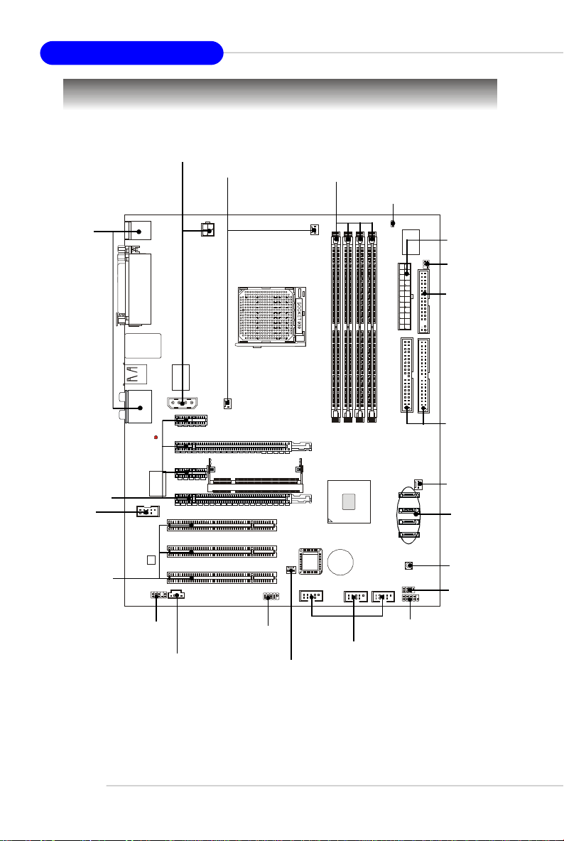
Quick Components Guide
PCIE_PW1,
JPW1, p. E-12
CPUFAN1,
SFAN1, p. E-12
DDR DIMMs, p. E-10
JCI1, p. E-15
I/O Ports,
p. E-14
PCI Express
Slots, p. E-20
J1394_1,
p. E-18
PCI Slots,
p. E-20
JAUD1, p. E-17
JCD1, p. E-15
JDB1, p. E-18
SFAN2, p. E-16
JUSB1/2/3, p. E-19
JFP1, p. E-17
ATX1, p. E-12
JIR1, p. E-17
FDD1, p. E-15
IDE1/2,
p. E-16
NBFAN1,
p. E-16
SATA1/2/
3/4, p. E-15
SW1, p. E-19
JFP2, p. E-17
E-6
Page 15
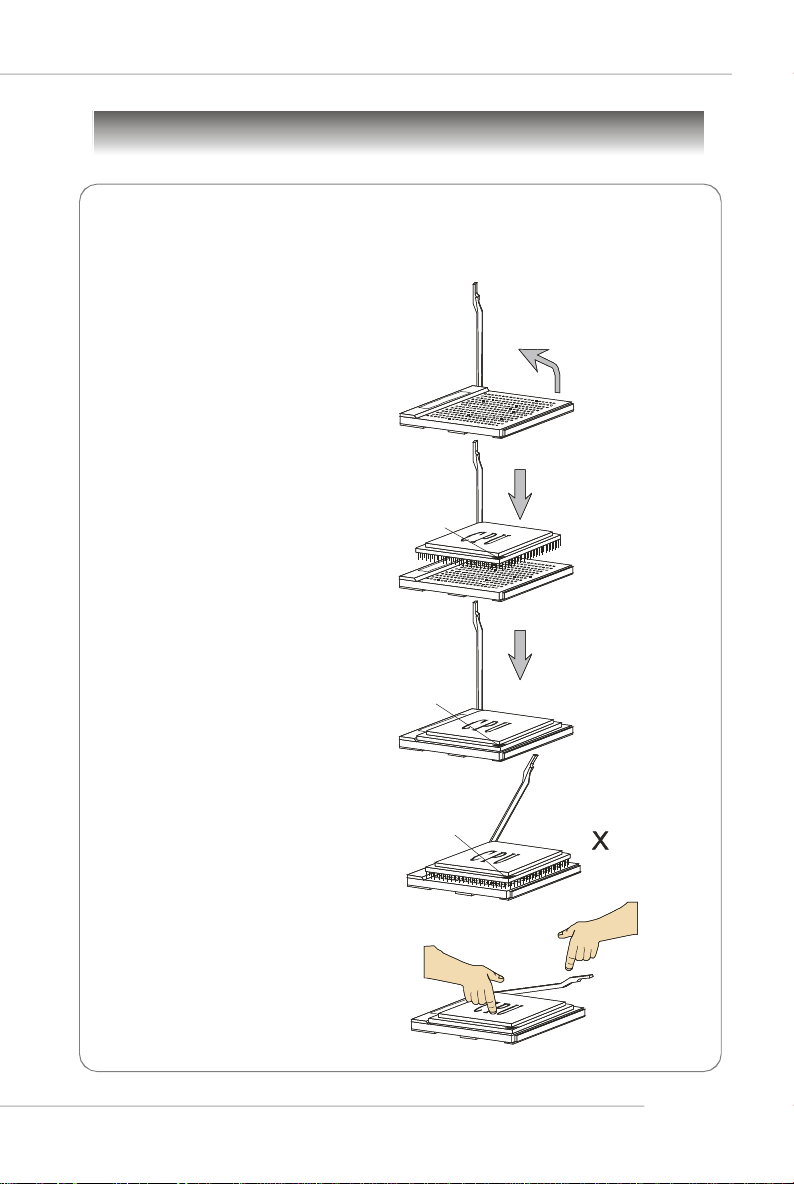
Central Processing Unit: CPU
Gold arrow
Gold Arrow
Gold Arrow
Correct CPU placement
O
Incorrect CPU placement
CPU Installation Procedures for Socket 939
1.Please turn off the power and
unplug the power cord before
installing the CPU.
Quick User’s Guide
Open Lever
2.Pull the lever sideways away
from the socket. Make sure to
raise the lever up to a 90-degree angle.
3.Look for the gold arrow on the
CPU. The gold arrow should point
as shown in the picture. The CPU
can only fit in the correct
orientation.
4.If the CPU is correctly installed,
the pins should be completely
embedded into the socket and
can not be seen. Please note
that any violation of the correct
installation procedures may
cause permanent damages to
your mainboard.
5. Press the CPU down firmly into
the socket and close the lever.
As the CPU is likely to move while
the lever is being closed, always close the lever with your
fingers pressing tightly on top of
the CPU to make sure the CPU is
properly and completely embedded into the socket.
Sliding
Plate
90 degree
Press down
the CPU
Close the lever
E-7
Page 16
MS-7185 ATX Mainboard
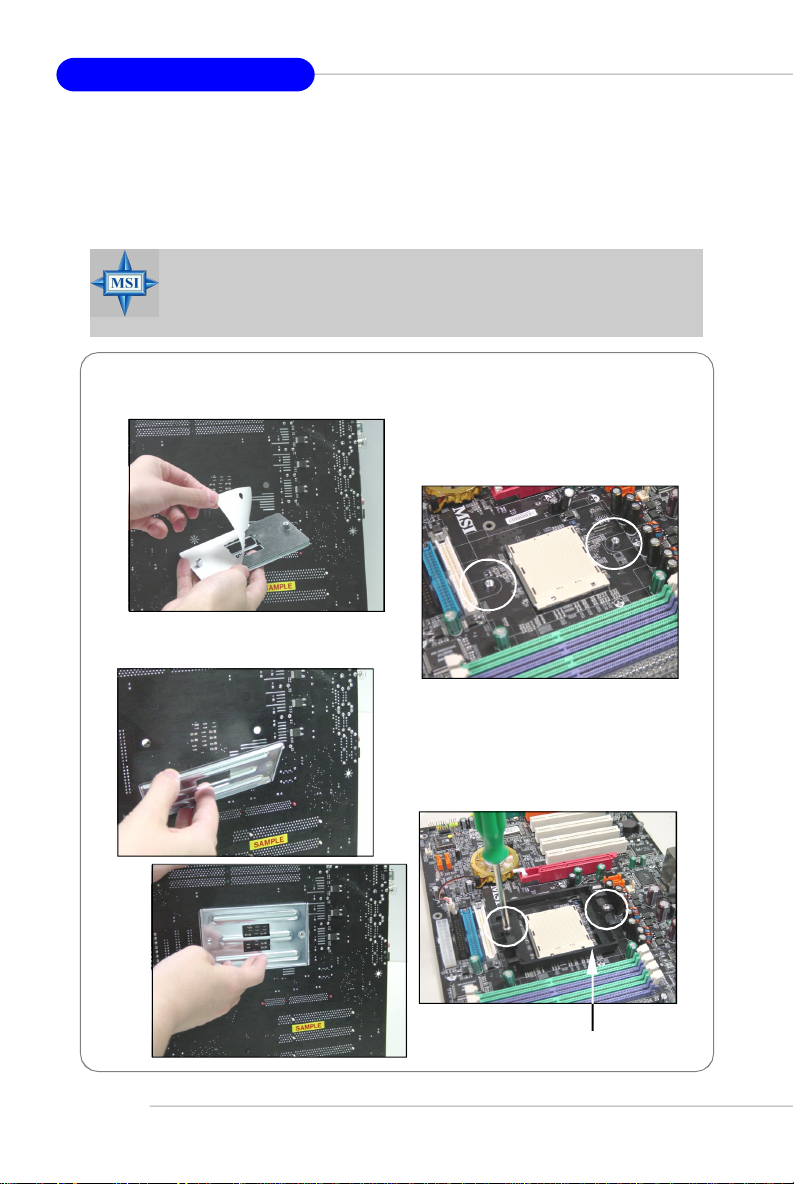
Installing AMD Athlon64 CPU Cooler Set
When you are installing the CPU, make sure the CPU has a heat sink and a
cooling fan attached on the top to prevent overheating. If you do not have
the heat sink and cooling fan, contact your dealer to purchase and install them
before turning on the computer.
MSI Reminds You...
Mainboard photos shown in this section are for demonstration of the
cooler installation for Socket 939 CPUs only. The appearance of
your mainboard may vary depending on the model you purchase.
1.Detach the shield off the
backplate’s paster.
2.Turn over the mainboard, and install
the backplate to the proper position.
3.Turn over the mainboard again, and
place the mainboard on the flat
surface. Locate the two screw
holes of the mainboard.
E-8
4.Align the retention mechanism and
the backplate.
Fix the retention mechanism and
the backplate with two screws.
retention mechanism
Page 17
Quick User’s Guide
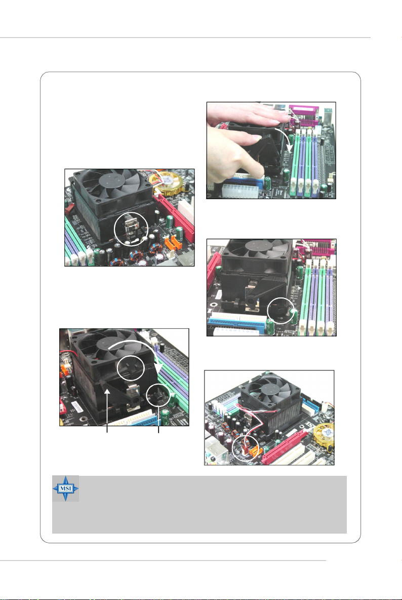
5.Position the cooling set onto the
retention mechanism.
Hook one end of the clip to hook
first, and then press down the
other end of the clip to fasten the
cooling set on the top of the
retention mechanism.
6.Locate the Fix Lever, Safety Hook
and the Fixed Bolt.
Lift up the intensive fixed lever.
Safety Hook
7.Fasten down the lever.
8.Make sure the safety hook completely clasps the fixed bolt of the
retention mechanism.
9.Attach the CPU Fan cable to the CPU
fan connector on the mainboard.
Fixed Lever
MSI Reminds You...
While disconnecting the Safety Hook from the fixed bolt, it is necessary to keep an eye on your fingers, because once the Safety Hook
is disconnected from the fixed bolt, the fixed lever will spring back
instantly.
Fixed Bolt
E-9
Page 18
MS-7185 ATX Mainboard
Memory
The mainboard provides 4 slots for 184-pin DDR DIMM (Double In-Line Memory Module)
modules and supports the memory size up to 4GB. You can install DDR 266/333/400
modules on the DDR DIMM slots (DIMM 1~4).
For the updated supporting memory modules, please visit http://www.msi.com.tw/
program/products/mainboard/mbd/pro_mbd_trp_list.php.
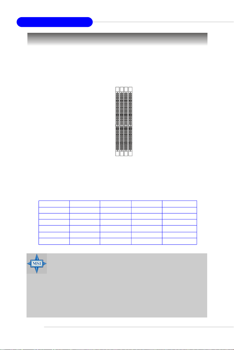
DIMM1~DIMM4
(from left to right)
DIMM Module Combination
Install at least one DIMM module on the slots. Each DIMM slot supports up to a maximum
size of 1GB. Users can install either single- or double-sided modules to meet their
own needs. Users may install memory modules of different type and density on
different-channel DDR DIMMs. However, memory modules of the same type and
density are required while using dual-channel DDR, or instability may happen.
DIMM1 (CH A) DIMM2 (CH B) DIMM3 (CH A)DIMM4 (CH B) Mode
128MB~1GB Single Channel
128MB~1GB Single Channel
128MB~1GB 128MB~1GB Single Channel
128MB~1GB 128MB~1GB Dual Channel
128MB~1GB 128MB~1GB Dual Channel
128MB~1GB 128MB~1GB 128MB~1GB 128MB~1GB Dual Channel
MSI Reminds You...
- The system operates ONLY when the DDR modules are installed in
accordance with the above-mentioned memory population rules.
- In dual-channel mode, make sure that you install memory modules
of the same type and density on DDR DIMMs.
- To enable successful system boot-up, always insert the memory
modules into the Channel A slots (DIMM1 or DIMM3) first.
- This mainboard DO NOT support the memory module installed
with more than 18 pieces of IC (integrated circuit).
- Do not support three memory modules.
E-10
Page 19
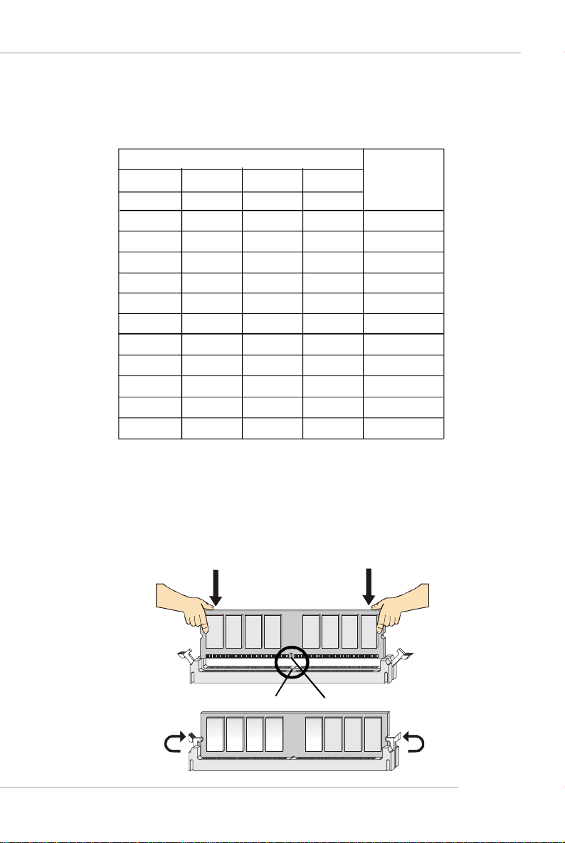
Recommended Memory Combination List
DIMM Slots
Green Green
DIMM1
S
-
D
-
S
D
S
D D
Purple
DIMM2 DIMM3 DIMM4
- -
-
-
-
-
-
S
- - D
S
D
S
D
S
-
D
S
D
-
- -
S
D
Purple
-
-
-
-
-
-
-
D
S
D
Quick User’s Guide
Max Speed
DDR 400
DDR 400
DDR 400
DDR 400
DDR 400
DDR 333
DDR 400
DDR 400
DDR 400
DDR 400
DDR 333
S: Single Side D: Double Side
Installing DDR Modules
1. The DDR DIMM has only one notch on the center of module. The module will
only fit in the right orientation.
2. Insert the DIMM memory module vertically into the DIMM slot. Then push it in
until the golden finger on the memory module is deeply inserted in the socket.
3. The plastic clip at each side of the DIMM slot will automatically close.
Volt
Notch
E-11
Page 20
MS-7185 ATX Mainboard
Power Supply
The mainboard supports ATX power supply for the power system. Before inserting
the power supply connector, always make sure that all components are installed
properly to ensure that no damage will be caused.
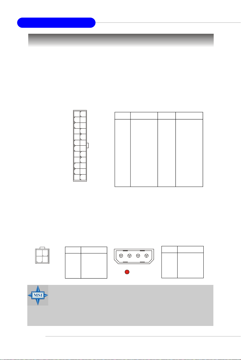
ATX 24-Pin System Power Connector: ATX1
This connector allows you to connect to an ATX power supply. To connect to the ATX
power supply, make sure the plug of the power supply is inserted in the proper
orientation and the pins are aligned. Then push down the power supply firmly into the
connector.
12
24
ATX1
1
13
ATX 4-Pin CPU Power Connector: JPW1
This connector provides 12V power output to the CPUs.
ATX1 Pin Definition
PIN SIGNAL
1 +3.3V
2 +3.3V
3 GND
4 +5V
5 GND
6 +5V
7 GND
8 PWR OK
9 5VSB
10 +12V
11 +12V
12 +3.3V
PIN SIGNAL
13 +3.3V
14 -12V
15 GND
16 PS-ON#
17 GND
18 GND
19 GND
20 3VSB
21 +5V
22 +5V
23 +5V
24 GND
ATX 4-Pin VGA Power Connector: PCIE_PW1
This connector is designed to connect 12V power supply for add-on PCI Express
graphics card(s). If users fail to connect this connector with an adequate power
supply, the alert LED (LED1) will glow.
PCIE_PW1 Pin Definition
PIN SIGNAL
12
1 5V
2 GND
3 GND
4 +12V
3 4
1
JPW1
E-12
JPW1 Pin Definition
PIN SIGNAL
2
1 GND
2 GND
3 12V
4 12V
PCIE_PW1
34
LED1
MSI Reminds You...
1. Maker sure that all three connectors are connected to adequate
ATX power supplies to ensure stable operation of the mainboard.
2. Power supply of 450watts (and above) is highly recommended
for system stability.
3. ATX 12V power connection should be greater than 20A.
Page 21
Quick User’s Guide
Important Notification about Power Issue
NForce chipset is very sensitive to ESD (Electrostatic Discharge), therefore this
issue mostly happens while the users intensively swap memory modules under S5
(power-off) states, and the power code is plugged while installing modules. Due to
several pins are very sensitive to ESD, so this kind of memory-replacement actions
might cause system chipset unable to boot. Please follow the following solution to
avoid this situation.
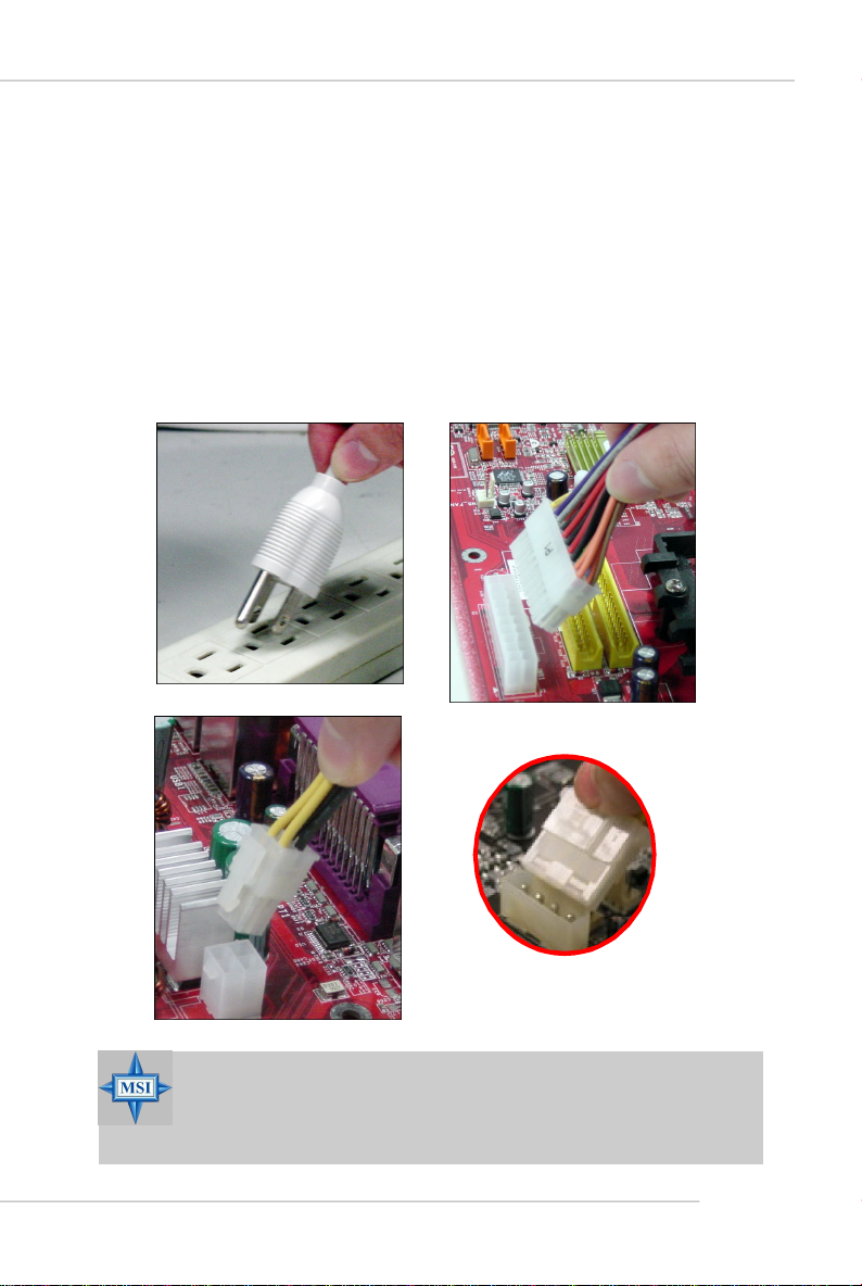
Unplug the AC power cable or unplug the power connectors (as shown below)
before the 1st installation or during system upgrade procedure.
Unplug the AC power cable Unplug the power connector
Unplug power connectors
MSI Reminds You...
Mainboard photos shown in this section are for demonstration only.
The appearance of your mainboard may vary depending on the model
you purchased.
E-13
Page 22
MS-7185 ATX Mainboard
Mouse
Keyboard
Serial Port
Parallel
1394 Port
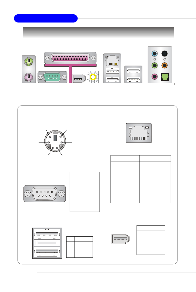
Back Panel
LAN
SPDIF
Out
(Coaxial)
USB Ports
L-In
L-Out
Mic
RS-Out
CS-Out
SPDIF Out
(Optical)
Mouse/Keyboard Connector
Pin5
Pin6 NC
Pin2 NC
Serial Port
1 2 3 4 5
6 7 8 9
Mouse/KBD Clock
Pin3 GNDPin4 VCC
Pin1
Mouse/KBD
DATA
PIN SIGNAL
1 DCD
2 SIN
3 SOUT
4 DTR
5 GND
6 DSR
7 RTS
8 CTS
9 RI
USB Ports
1 2 3 4
PIN SIGNAL
1 VCC
2 -Data
3 +Data
4 GND
RJ-45 LAN Jack
8 1
Gigabit LAN
PIN SIGNAL DESCRIPTION
1 D0P Differential Pair 0+
2 D0N Differential Pair 03 D1P Differential Pair 1+
4 D2P Differential Pair 2+
5 D2N Differential Pair 26 D1N Differential Pair 17 D3P Differential Pair 3+
8 D3N Differential Pair 3-
IEEE 1394 Port
PIN SIGNAL
246
1
35
1 PWR
2 GND
3 TPB4 TPB+
5 TPA6 TPA+
E-14
Page 23
Quick User’s Guide
Connectors
Floppy Disk Drive Connector: FDD1
The mainboard provides a standard floppy disk drive connector that supports 360K, 720K, 1.2M, 1.44M and 2.88M floppy disk types.
CD-In Connector: JCD1
This connector is provided for CD-ROM audio.
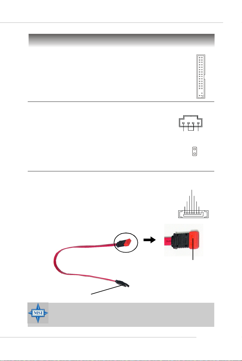
Chassis Intrusion Switch Connector: JCI1
This connector is connected to a 2-pin chassis switch. If the
chassis is opened, the switch will be short. The system will record
this status and show a warning message on the screen. To clear
the warning, you must enter the BIOS utility and clear the record.
SATA RAID Connectors: SATA1/SATA2/SATA3/SATA4
The nVIDIA nForceTM4 SLI provides a hybrid solution that combines
four independent SATA ports for support of up to four Serial ATA
(Serial ATA RAID) drives and utilizes nVIDIA Serial ATA software
RAID to support RAID levels 0, 1, 0+1, and JBOD for easy
management of the storage subsystems. These connectors support
2nd generation serial ATA data rates of 300 MB/s and are fully
compliant with Serial ATA II specifications.
Serial ATA cable
Take out the dust cover and
connect to the hard disk
devices
JCD1
R
GND
CINTRU
RXN
RXP
GND
GND
JCI1
GND
L
2
1
TXN
TXP
GND
Connect to SATA1/2/3/4
MSI Reminds You...
Please do not fold the Serial ATA cable into 90-degree angle. Otherwise,
data loss may occur during transmission.
E-15
Page 24
MS-7185 ATX Mainboard
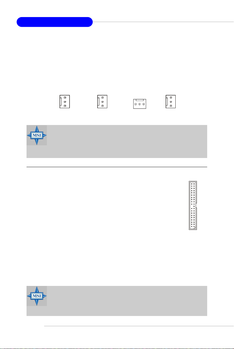
Fan Power Connectors: CPUFAN1 / SFAN1 / SFAN2 / NBFAN1
The fan power connectors support system cooling fan with +12V. When connecting
the wire to the connectors, always take note that the red wire is the positive and
should be connected to the +12V, the black wire is Ground and should be connected
to GND. If the mainboard has a System Hardware Monitor chipset onboard, you must
use a specially designed fan with speed sensor to take advantage of the CPU fan
control.
+1 2V
GND
SFAN2
NC
GND
+12V
SENSOR
NBFAN1
GND
+12V
SENSOR
CPUFAN1
SFAN1
GND
+12V
SENSOR
MSI Reminds You...
1.CPUFAN1 supports fan control. You can install Core Center utility
that will automatically control the CPU fan speed according to the
actual CPU temperature.
2. Please refer to the recommended CPU fans at AMD® official website.
ATA133 Hard Disk Connectors: IDE1 & IDE2
The mainboard has a 32-bit Enhanced PCI IDE and Ultra DMA 66/100/133
controller that provides PIO mode 0~4, Bus Master, and Ultra DMA 66/100/
133 function. You can connect up to four hard disk drives, CD-ROM and
other IDE devices.
The Ultra ATA133 interface boosts data transfer rates between the
computer and the hard drive up to 133 megabytes (MB) per second. The
new interface is one-third faster than earlier record-breaking Ultra ATA/
100 technology and is backwards compatible with the existing Ultra ATA
interface.
IDE1 (Primary IDE Connector)
The first hard drive should always be connected to IDE1. IDE1 can connect a Master
and a Slave drive. You must configure second hard drive to Slave mode by setting the
jumper accordingly.
IDE2 (Secondary IDE Connector)
IDE2 can also connect a Master and a Slave drive.
MSI Reminds You...
If you install two hard disks on cable, you must configure the second
drive to Slave mode by setting its jumper. Refer to the hard disk documentation supplied by hard disk vendors for jumper setting instructions.
E-16
Page 25
Quick User’s Guide
IrDA Infrared Module Header: JIR1
The connector allows you to connect to IrDA Infrared module. You must configure the
setting through the BIOS setup to use the IR function. JIR1 is compliant with Intel
Front Panel I/O Connectivity Design Guide.
JIR1
IRRX
GND
IRTX
NC
VCC5
Front Panel Connectors: JFP1, JFP2
The mainboard provides two front panel connectors for electrical connection to the
front panel switches and LEDs. The JFP1 is compliant with Intel® Front Panel I/O
Connectivity Design Guide.
PWR_SW_P
FP PWR/SLP
FP PWR/SLP
HDD_LED_P
HDD_LED_N
PWR_SW_N
Reserved
RST_SW_P
RST_SW_N
JFP1
SPK-
GND
BUZ+
SLED
BUZ-
PLED
SPK+
JFP2
®
Front Panel Audio Connector: JAUD1
The JAUD1 front panel audio connector allows you to connect to the front panel
audio and is compliant with Intel® Front Panel I/O Connectivity Design Guide.
JAUD1
AUD_VCC
AUD_GND
AUD_MIC
AUD_MIC_BIAS
MSI Reminds You...
If you don’t want to connect to the front audio header, pins
5 & 6, 9 & 10 have to be jumpered in order to have signal
output directed to the rear audio ports. Otherwise, the
Line-Out connector on the back panel will not function.
AUD_RET_R
2
1
AUD_FPOUT_R
10
AUD_RET_L
AUD_FPOUT_L
9
HP_ON
6
10
5
9
E-17
Page 26
MS-7185 ATX Mainboard
D-Bracket™ 2 Connector: JDB1
The mainboard comes with a JDB1 connector for you to
connect to D-Bracket™ 2. D-Bracket™ 2 is an external
USB Bracket that supports both USB1.1 & 2.0 spec. It
integrates four LEDs and allows users to identify system problems through 16 various combinations of LED
signals.
Connect to JDB1
D-Bracket™ 2
(Optional)
Connected to JUSB1/2/3
DBR2
DBR1
DBG1
DBG2
JDB1
DBR3
2
1
1 2
3 4
DBG3
DBR4
10
NC
9
DBG4
LEDs
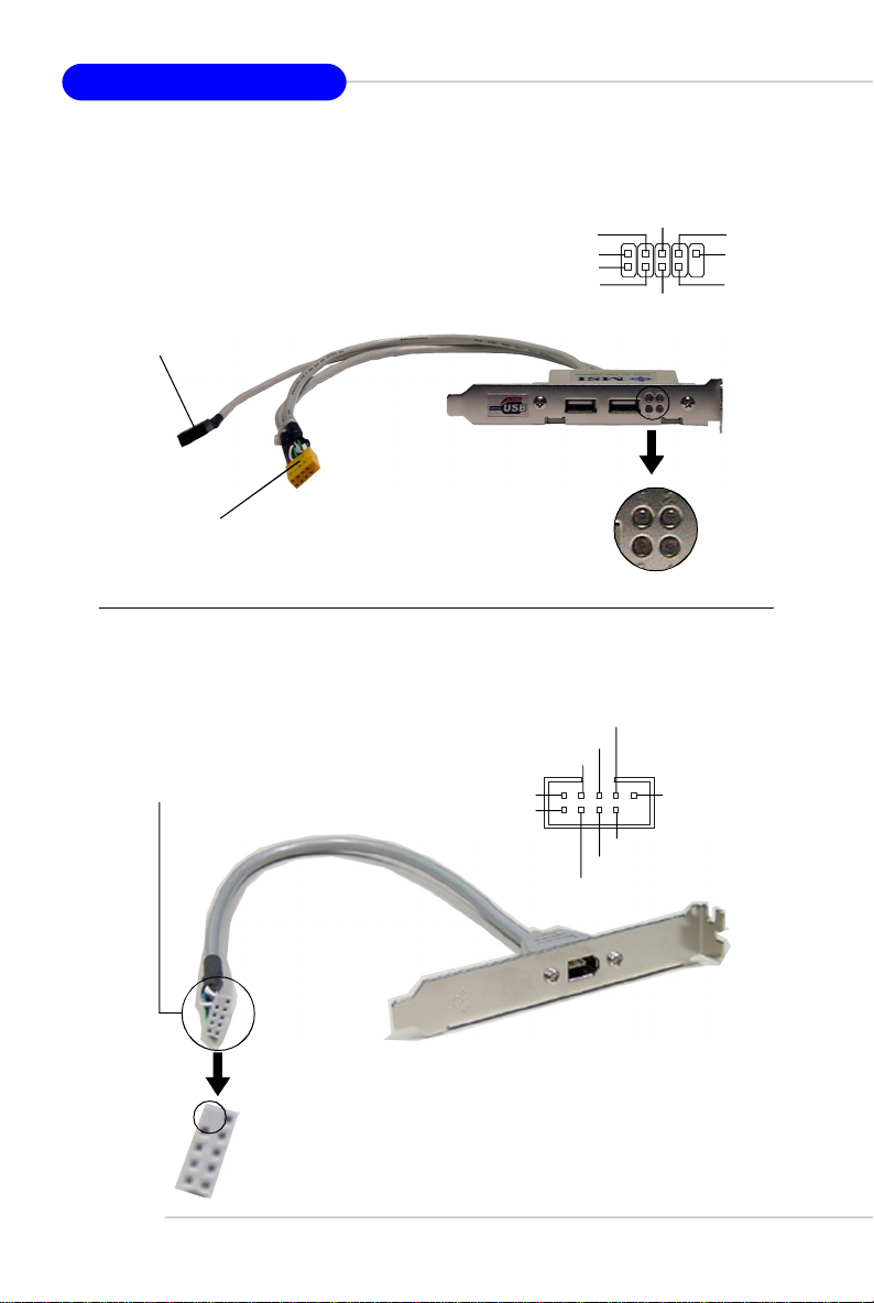
IEEE 1394 Connector: J1394_1
The mainboard provides one 1394 pinheader that allows you to connect IEEE 1394
ports via an external IEEE1394 bracket.
Connected to J1394_1 (the 1394
pinheader in GREEN color)
J1394_1
TPA-
TPA+
Cable Power
TPB-
GND
2 10
1
Cable Power
TPB+
GND
GND
E-18
IEEE1394 Bracket (Optional)
Foolproof
design
Page 27
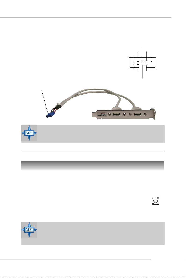
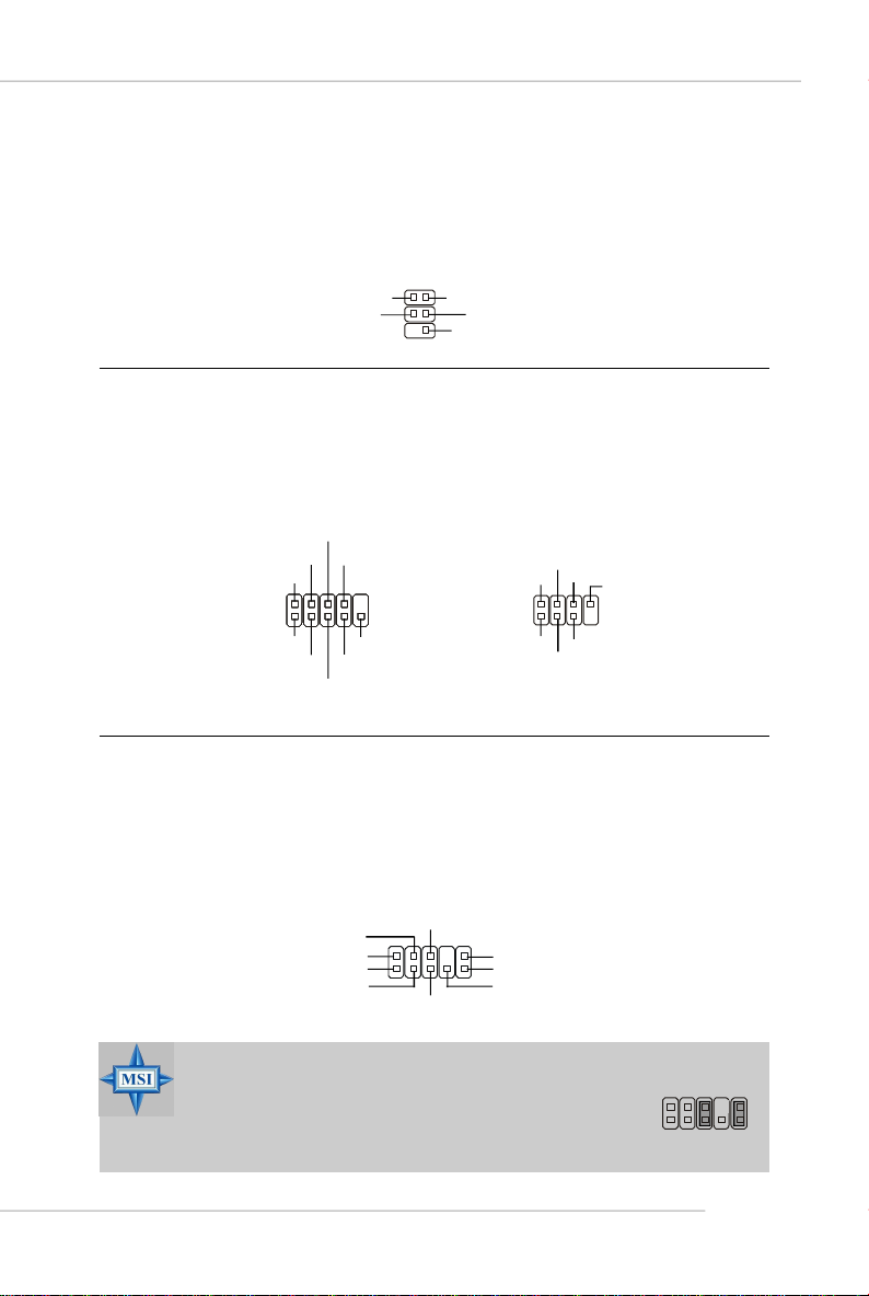
Front USB Connectors: JUSB1, JUSB2, JUSB3
The mainboard provides three standard USB 2.0
pin headers. USB 2.0 technology increases data
transfer rate up to a maximum throughput of
480Mbps, which is 40 times faster than USB 1.1,
and is ideal for connecting high-speed USB
interface peripherals such as USB HDD, digital
cameras, MP3 players , printers, modems
and the like.
Connect to JUSB1, JUSB2, or JUSB3
(the USB pinheader in YELLOW color)
USB 2.0 Bracket
(Optional)
MSI Reminds You...
Note that the pins of VCC and GND must be connected correctly to
avoid possible damage.
JUSB1/2/3
Quick User’s Guide
USB1+
USB1-
GND
2
1
VCC
VCC
USB0-
USBOC
10
GND
USB0+
Button
Clear CMOS Button: SW1
CMOS stands for Complementary Metal-Oxide Semiconductor and is more specifically referred to as CMOS RAM. It is a tiny 64-byte region of memory that,
owing to battery power, retains system configuration data when the PC is
shut off. With the CMOS RAM, the system can automatically boot OS every
time it is turned on. If you want to clear the system configuration, press the
SW1 button to have the data erased.
MSI Reminds You...
You can clear CMOS by pressing this button while the system is off.
Avoid clearing CMOS while the system is on; it will damage the
mainboard.
SW1
E-19
Page 28
MS-7185 ATX Mainboard
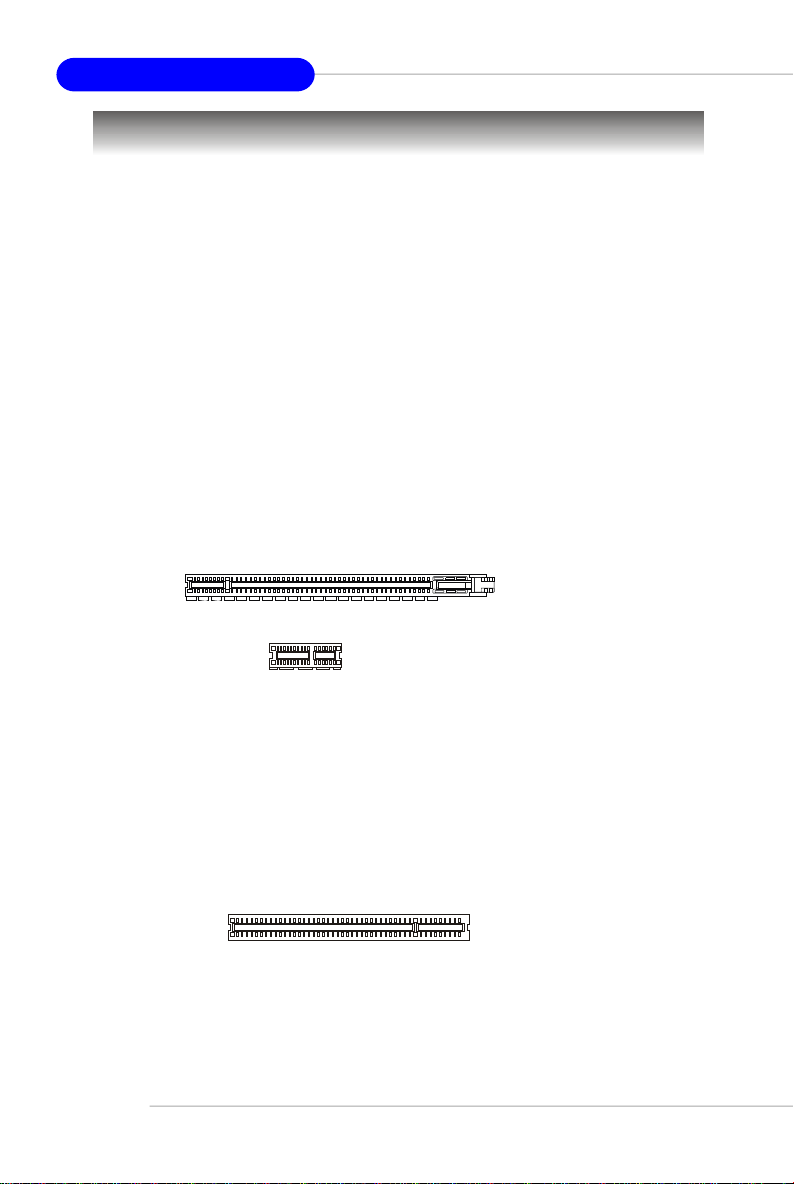
Slots
The motherboard provides two PCI Express x1 slots, two PCI Express x16 slots, and
three 32-bit PCI slots.
PCI (Peripheral Component Interconnect) Express Slots
The PCI Express slots support high-bandwidth, low pin count, and serial interconnect
technology. You can insert the expansion cards to meet your needs. When adding or
removing expansion cards, make sure that you unplug the power supply first.
PCI Express architecture provides a high performance I/O infrastructure for Desktop
Platforms with transfer rates starting at 2.5 Giga transfers per second over a PCI
Express x1 lane for Gigabit Ethernet, TV Tuners, 1394 controllers, and general purpose I/O. Also, desktop platforms with PCI Express Architecture will be designed to
deliver highest performance in video, graphics, multimedia and other sophisticated
applications. Moreover, PCI Express architecture provides a high performance graphics
infrastructure for Desktop Platforms doubling the capability of existing AGP 8x designs with transfer rates of 4.0 GB/s over a PCI Express x16 lane for graphics
controllers, while PCI Express x1 supports transfer rate of 250 MB/s.
PCI Express x16 slot
PCI Express x1 slot
PCI (Peripheral Component Interconnect) Slots
The PCI slots allow you to insert the expansion cards to meet your needs. When
adding or removing expansion cards, make sure that you unplug the power supply
first. Meanwhile, read the documentation for the expansion card to make any necessary hardware or software settings for the expansion card, such as jumpers,
switches or BIOS configuration.
PCI Slots
E-20
Page 29

Quick User’s Guide
PCI Interrupt Request Routing
The IRQ, acronym of interrupt request line and pronounced I-R-Q, are hardware lines
over which devices can send interrupt signals to the microprocessor. The PCI IRQ
pins are typically connected to the PCI bus pins as follows:
Order 1 Order 2 Order 3 Order 4
PCI Slot 1 INT A# INT B# INT C# INT D#
PCI Slot 2 INT B# INT C# INT D# INT A#
PCI Slot 3 INT C# INT D# INT A# INT B#
NV SLI (Scalable Link Interface) Slot: PCI_E4
NVIDIA SLI (Scalable Link Interface) technology allows two GPUs to run in tandem
within a system to achieve up to twice the performance of a single graphics card. To
utilize this technology, the two GPU cards must be
connected by an SLI bridge card.
You can find an SLI switch card on the mainboard
configured to non-SLI mode by default.
SLI Switch Card
If you intend to use the SLI interface for better graphics performance, please refer to
the following instructions.
1. Push the retaining clips (on the sides of the SLI slot) outwards to release the
SLI switch card.
MSI Reminds You...
Make sure that you unplug the power supply before removing the SLI
switch card.
SLI Bridge Card
non-SLI mode
E-21
Page 30

MS-7185 ATX Mainboard
2. Remove the SLI switch card. Flip it over to the other side (SLI mode side) and
insert it slantwise (at 45-degree angle) into the SLI slot.
SLI mode
3. Press down the SLI switch card. The retaining clips (on the sides of the SLI
slot) will automatically lock onto the notches in the ends of the card. The card
should securely fit into the slot. Before installing or removing the SLI switch
card, make sure that you unplug the power supply first.
4. After configuring the switch card to SLI mode, you can now install two
graphics cards on PCI Express x16 slots. With two cards installed, an SLI
bridge card is required to connect the atop golden fingers of these two
graphics cards. Please note that although you have installed two graphics
cards, only the video outputs on the first card will work. Hence, you only
need to connect a monitor to the first PCI Express card.
E-22
SLI bridge
card
MSI Reminds You...
1. Mainboard photos shown in this section are for demonstration only.
The appearance of your mainboard may vary depending on the
model you purchase.
2. If you intend to install only ONE x16 graphics card, make sure
that:a. your graphics card is Installed on the PCI_E1 slot;
b. the SLI switch card is set to non-SLI mode.
3. If you intend to install TWO x16 graphics cards, make sure that:
a. these two graphics cards are of the same brand and
specifications;
b. the SLI switch card is set to SLI mode.
Page 31

Quick User’s Guide
5. After the hardware installation is completed, restart the system and install
the NV SLI driver/utility. A configuration panel will be provided for Multi-GPU
control. Check the Enable multi-GPU box to enable the SLI function for the
onboard graphics cards (concerning the details of multi-GPU settings, please
refer to your graphics card manual) .
Check the box
6. Restart your system and a pop-up will show in the system tray confirming
that Multi-GPU has been enabled.
MSI Reminds You...
1. If you want to remove one graphics card and quit the SLI function,
make sure that you reset the SLI switch card (SLI mode to non-SLI
mode) and disable the "MultiGPU" function.
2. The onboard PCIE_PW1 VGA power connector (p. E-12) is designed to connect 12V power supply for add-on PCI Express graphics card(s). Make sure that you connect an adequate power supply
to this PCIE_PW1 connector (or to the power connection on the
graphics card) to ensure stable operation of the graphics card.
E-23
Page 32

MS-7185 ATX Mainboard
Restore the previous CMOS value from CMOS, only for
BIOS Setup
Power on the computer and the system will start POST (Power On Self Test) process.
When the message below appears on the screen, press <DEL> key to enter Setup.
Press DEL to enter SETUP
If the message disappears before you respond and you still wish to enter Setup,
restart the system by turning it OFF and On or pressing the RESET button. You may
also restart the system by simultaneously pressing <Ctrl>, <Alt>, and <Delete> keys.
Control Keys
<↑>
<↓>
<←>
<→>
<Enter> Select the item
<Esc> Jumps to the Exit menu or returns to the main menu
<+/PU> Increase the numeric value or make changes
<-/PD> Decrease the numeric value or make changes
<F1> General help, only for Status Page Setup Menu and
<F5>
<F7> Load Optimized defaults
<F10> Save all the CMOS changes and exit
MSI Reminds You...
The items under each BIOS category described in this section are
under continuous update for better system performance. Therefore,
the description may be slightly different from the latest BIOS and
should be held for reference only.
Move to the previous item
Move to the next item
Move to the item in the left hand
Move to the item in the right hand
from a submenu
Option Page Setup Menu
Option Page Setup Menu
E-24
Page 33

Quick User’s Guide
The Main Menu
Standard CMOS Features
Use this menu for basic system configurations, such as time, date etc.
Advanced BIOS Features
Use this menu to setup the items of AWARD® special enhanced features.
Advanced Chipset Features
Use this menu to change the values in the chipset registers and optimize your system’s
performance.
Integrated Peripherals
Use this menu to specify your settings for integrated peripherals.
Power Management Setup
Use this menu to specify your settings for power management.
PNP/PCI Configurations
This entry appears if your system supports PnP/PCI.
H/W Monitor
This entry shows your PC health status.
Cell Menu
Use this menu to specify your settings for CPU/AGP frequency/voltage control and
overclocking.
Load Optimized Defaults
Use this menu to load the default values set by the mainboard manufacturer specifically for optimal performance of the mainboard.
BIOS Setting Password
Use this menu to set the password for BIOS.
E-25
Page 34

MS-7185 ATX Mainboard
Cell Menu
Current CPU / DDR Clock
These two items show the current clocks of CPU & DDR. Read-only.
High Performance Mode
This field allows you to select the DDR timing setting. Setting to [Optimized] enables
Adjust DDR Memory Frequency automatically to be determined by SPD. Selecting
[Manual] allows users to configure these fields manually. Setting options: [Optimized],
[Manual].
Aggressive timing
This item allows you to enable or disable the memory clock. When [Enabled] is selected,
the timing delay of memory will be shorten to increase the performance. Setting
options: [Enabled], [Disabled].
Dynamic Overclocking
Dynamic Overclocking Technology is the automatic overclocking function, included in
the MSITM’s newly developed CoreCell
balance of CPU while running programs, and to adjust the best CPU frequency
automatically. When the motherboard detects CPU is running programs, it will speed
up CPU automatically to make the program run smoothly and faster. When the CPU is
temporarily suspending or staying in the low load balance, it will restore the default
settings instead. Usually the Dynamic Overclocking Technology will be powered only
when users' PC need to run huge amount of data like 3D games or the video process,
and the CPU frequency need to be boosted up to enhance the overall performance.
Setting options:
[Disabled] Disable Dynamic Overclocking function.
[Private] 1st level of overclocking, increasing the CPU frequency by 1%.
[Sergeant] 2nd level of overclocking, increasing the CPU frequency by 3%.
[Captain] 3rd level of overclocking, increasing the CPU frequency by 5%.
[Colonel] 4th level of overclocking, increasing the CPU frequency by 7%.
TM
Technology. It is designed to detect the load
E-26
Page 35

Quick User’s Guide
[General] 5th level of overclocking, increasing the CPU frequency by 9%.
[Commander] 6th level of overclocking, increasing the CPU frequency by 11%.
MSI Reminds You...
Even though the Dynamic Overclocking Technology is more stable
than manual overclocking, basically, it is still risky. Users are suggested to check their CPU’s overclocking capability first. If the PC
appears to be unstable or reboot incidentally, it's better to disable
Dynamic Overclocking or to lower the level of overclocking options.
By the way, if you need to conduct overclocking manually, you also
need to disable Dynamic Overclocking first.
Adjust CPU FSB Frequency
This item allows you to select the CPU Front Side Bus clock frequency (in MHz).
Select the number between [200]~[400] for needed frequency.
HT Frequency
This setting specifies the maximum operating frequency of the link’s transmitter clock.
Setting options: [1x], [1.5x], [2x], [2.5x], [3x], [4x], [5x].
HT Width
This field allows you to set the HT Width between CPU & Chip.↑ mark means Chip to
CPU HT Width. And ↓ mark means CPU to Chip HT Width. Setting options: [ ↓ 8 ↑ 8], [
↓ 16 ↑ 8], [↓ 8 ↑16], [ ↓16 ↑16].
CPU Spread Spectrum
This setting is used to enable or disable the CPU Spread Spectrum feature. When
overclocking the CPU, always set it to [Disabled]. Setting options: [Center Spread],
[Disabled].
SATA Spread Spectrum
This setting is used to enable or disable the SATA Spread Spectrum feature. When
overclocking the CPU, always set it to [Disabled]. Setting options: [Disabled], [Down
Spread].
PCIE Spread Spectrum
This setting is used to enable or disable the PCI Express Spread Spectrum feature.
When overclocking the CPU, always set it to [Disabled]. Setting options: [Disabled],
[Down Spread].
PCIE Clock
This item allows you to select the PCIE Bus clock frequency (in MHz). Select the
number between [100]~[145] for needed frequency.
SSE/ SSE2 Instructions
This setting disables/enables the SSE/SSE2 Instructions. The Streaming SIMD Extensions (SSE) were introduced in the Pentium III processor. The SSE extensions consist of a new set of instructions and a new set of registers. These instructions and
registers are designed to allow Single-Instruction Multiple-Data (SIMD) computations
to be made on single-precision floating-point numbers.
The Streaming SIMD Extensions 2 (SSE2) were introduced in the Pentium 4 and Intel
E-27
Page 36

MS-7185 ATX Mainboard
Xeon processors. They consist of a new set of instructions that operate on the XXM
and MXCSR registers and perform SIMD operations on double-precision floatingpoint values and on integer values.Several of these new SSE/SSE2 instructions also
operate in the MMX registers. Setting options: [Enabled], [Disabled].
Cool’n’Quiet
This feature is especially designed for AMD Athlon processor, which provides a CPU
temperature detecting function to prevent your CPU’s from overheating due to the
heavy working loading. Setting options: [Disabled], [Auto].
MSI Reminds You...
For the purpose of ensuring the stability of Cool'n'Quiet function, it is
always recommended to have the memories plugged in DIMM1.
Adjust CPU Ratio
This item lets you adjust the CPU ratio. Setting to [Startup] enables the CPU running
at the fastest speed which is detected by system. Setting options are: [Startup],
[x4]~[x25].
Adjust CPU VID
This item lets you adjust the CPU VID. Setting to [Startup] enables the CPU running
at the default VID which is detected by system. Setting options are: [Startup], [0.
825V], [0.850V],[0.875V],~, [1.550V].
Extra CPU Voltage
This feature allows you to add extra voltage to the CPU. Setting options are: [By
CPU VID], [Over VID 3.3%], [Over VID 6.6%],[Over VID 8.3%].
CPU Voltage
This setting shows the voltage of the CPU.
Memory Voltage
Adjusting the DDR voltage can increase the DDR speed. Any changes made to this
setting may cause a stability issue, so changing the DDR voltage for long-term
purpose is NOT recommended. Setting options: [Auto], [2.50V] ~ [2.85V].
NF4 Voltage
NF4 voltage is adjustable in the field. Setting options: [1.50V] ~ [1.85V].
MSI Reminds You...
The settings shown in different color in CPU Voltage, Memory
Voltage and NF4 Voltage help to verify if your setting is proper for
your system.
Gray: Default setting.
Yellow:High performance setting.
Red: Not recommended setting and the system may be
Changing CPU Voltage, Memory Voltage and NF4 Voltage may
result in the instability of the system; therefore, it is NOT recommended to change the default setting for long-term usage.
unstable.
E-28
Page 37

Kurzanleitung
K8N SLI Series
(MS-7185 V1.X)
ATX Mainboard
Deutsch
D-1
Page 38

MS-7185 ATX Mainboard
D-2
Page 39

Kurzanleitung
MS-7185 (V1.X)
Kurzanleitung
Danke, dass Sie mit das ATX Mainboard K8N SLI Series (MS-7185
V1.X), ein exzellentes Mainboard von MSI, erworben haben.
Aufbauend auf dem innovativen nVIDIA® nForceTM4 SLI Chipsatz
für ein optimales und effizientes System, nimmt das K8N SLI Series
die fortschrittlichen AMD K8 AthlonTM 64 X2 Dual-Core / Athlon
64 FX / AthlonTM 64 Prozessoren im Sockel 939 auf und unterstützt
bis zu vier 144-bit DDR DIMMs (mit 200, 266, 333 und 400 MHz) womit es einen maximalen Speicherausbau auf bis zu 4GB ermöglicht.
TM
MSI weist darauf hin...
1. Beachten Sie bitte, dass die beigelegte MSI Treiber/Utility CD
AUSCHLIESSLICH dieses Mainboard mit Windows 2000/XP
Systemtreibern unterstützt.
2. Um ein bootfähiges RAID Laufwerk unter Windows 2000 zu
erzeugen, wird Microsoft’s Windows 2000 Service Pack 4
(SP4) benötigt. Da der Endanwender nicht ohne SP4 booten
kann, muss eine kombinierte Installations- CD erstellt
werden, bevor der Versuch unternommen werden kann, das
Betriebssystem auf ein bootfähiges RAID Laufwerk zu
installieren.
Entnehmen Sie bitte folgender Website, wie Sie eine
kombinierte Installations- CD erstellen:
http://www.microsoft.com/windows2000/downloads/
servicepacks/sp4/HFdeploy.htm
D-3
Page 40

MS-7185 ATX Mainboard
Mainboard Spezifikationen
CPU
† Unterstützt den Sockel 939 für AMD K8 AthlonTM 64 X2 Dual-Core / AthlonTM 64 FX
/ AthlonTM 64 Prozessoren
† Unterstützt CPUs bis hin zum Athlon64 4200+ oder höher
(Die neuesten Informationen zu unterstützten Prozessoren finden Sie unter http:/
/www.msi.com.tw/program/products/mainboard/mbd/pro_mbd_cpu_support.
php)
Chipsatz
† nVIDIA nForce4 SLI
- HyperTransport Anbindung an AMD K8 AthlonTM 64 X2 Dual-Core / AthlonTM 64 FX
/ AthlonTM 64 CPU
- HyperTransport unterstützt Geschwindigkeiten von bis zu 1GHz (2000MT/s)
- Unterstützt 2 PCI Express x16/ x1 Schnittstellen
- Zwei unabhängige SATA Kontroller, für vier Laufwerke
- Dual Ultra ATA 133/100/66 IDE Kontroller
- Unterstützt Hochgeschwindigkeits- USB2.0 Ports
- IEEE802.3 nVIDIA MAC für 1000BASE-T
Hauptspeicher
† Unterstützt acht Zweikanal DDR 266/333/400 Speicherbänke für vier 184-pin
DDR DIMMs
† Unterstützt einen maximalen Speicherausbau auf bis zu 4GB
† Unterstützt 2,5V DDR SDRAM DIMMs
(Um den letzten Stand bezüglich der unterstützten Speichermodule zu erhalten,
besuchen Sie bitte http://www.msi.com.tw/program/products/mainboard/mbd/
pro_mbd_trp_list.php.)
Steckplätze
† Drei 32-bit/33Mhz Master PCI Bus Slots, einschließlich eines orangefarbenen,
der 2 Master für MSI PCI Karten mit Spezialfunktion bereit stellt (z.B. Wireless
LAN und Bluetooth Kombikarte)
† Zwei PCI Express x1 Slots (erfüllen die PCI Express Bus Spezifikation V1.0a)
† Zwei PCI Express x16 Sockel, die durch automatische Erkennung oder über
Softwareeinstellung zwischen Normal und dem SLI Betrieb umschaltbar sind
(erfüllen die PCI Express Bus Spezifikation V1.0a)
SLI Modus - Primärer PCI _ E Slot ist kompatibel mit PCI Express x 8
- Sekundärer PCI_E Slot ist kompatibel mit PCI Express x 8
Normaler Modus - Primärer PCI_E Slot ist kompatibel mit PCI Express x 16
Festplattenschnittstellen
† Dual IDE Kontroller im nVIDIA® nForceTM4 SLI Chipsatz enthalten
- Bietet IDE HDD/CD-ROM Zugriff mit den Betriebsmodi PIO, Bus Mastering und
Ultra DMA 133/100/66
- Bis zu vier IDE Geräte anschließbar
† Zwei unabhängige SATA Kontroller im nVIDIA® nForceTM4 SLI Chipsatz enthalten
- NV RAID unterstützt 4 SATA II Ports mit Übertragungsraten von bis zu 300MB/s
- Sekundärer PCI_E Slot ist kompatibel mit PCI Express x 1
D-4
Page 41

Kurzanleitung
NV RAID (Software)
† Unterstützt bis zu 4 SATA und 4 PATA133 Festplatten
-Bietet RAID 0 oder 1, 0+1, sowie JBOD ( Betrieb ohne Raid- Funktionalität)
-RAID Funktionalität verfügbar für PATA133+SATA Festplatten oder 4 SATA
Festplatten
Peripherieanschlüsse onboard
† 1 Anschluss für 1 Diskettenlaufwerk mit 360 KB, 720 KB, 1,2 MB, 1,44 MB oder
2,88 MB
† 1 PS/2 Tastaturanschluss
† 1 PS/2 Mausanschluss
† 1 Serielle Schnittstelle
† 1 Parallele Schnittstelle, die die Betriebsmodi SPP/EPP/ECP unterstützt
† 1 RJ-45 Port (mit LEDs)
† 10 USB Anschlüsse (6 vordere und 4 hintere)
† 2 IEEE 1394 (1 vordere und 1 hintere)
† 1 Audio Buchse (5-in-1), koaxial/Glasfaser SPDIF Ausgang
† 1 IrDA Stiftleiste
† 1 D-Bracket 2 Stiftleistenanschluss
† 1 CD-Eingang als Stiftleiste
Onboard LAN
† nVIDIA MAC für 1000BASE-T
† Marvell PHY 88E1111 10/100/1000 Fast Ethernet
Onboard Audio
† Realtek ALC850 8-Kanal Codec
- 8-Kanal DA Anschluss mit 48 KHz
- Erfüllt die Spezifikation AC97 2.3
- Erfüllt die Audioleistungsanforderungen an Systeme gemäß PC 97/2001
- Erfüllt die Microsoft WHQL / WLP 2.0 Audioanforderungen
Onboard IEEE 1394
† VIA VT6307 IEEE 1394 Kontroller
BIOS
† Das Mainboard- BIOS verfügt über “Plug & Play”- Funktionalität, mit der ange-
schlossene Peripheriegeräte und Erweiterungskarten automatisch erkannt
werden.
† Das Mainboard stellt ein Desktop - Management - Interface (DMI) zur Verfügung,
welches automatisch die Spezifikationen Ihres Mainboards aufzeichnet.
† Unterstützt das Hochfahren aus dem Netzwerk, von USB 1.1 und 2.0 Geräten und
SATA Festplatten
Abmessungen
† ATX Form Faktor (30,5 cm X 24,5 cm)
Montage
† 9 Montagebohrungen
D-5
Page 42

MS-7185 ATX Mainboard
Kurzeinführung Komponenten
PCIE_PW1,
JPW1, S. D-12
CPUFAN1,
SFAN1, S. D-12
DDR DIMMs, S. D-10
Ein-/Ausgabe
Ports, S. D-14
PCI Express
Slots, S. D-20
J1394_1,
S. D-18
PCI Slots,
S. D-20
JCI1, S. D-15
ATX1, S. D-12
JIR1, S. D-17
FDD1, S. D-15
IDE1/2,
S. D-16
NBFAN1,
S. D-16
SATA1/2/
3/4, S. D-15
SW1, S. D-19
JFP2, S. D-17
D-6
JAUD1, S. D-17
JCD1, S. D-15
JDB1, S. D-18
SFAN2, S. D-16
JFP1, S. D-17
JUSB1/2/3, S. D-19
Page 43

Hauptprozessor: CPU
Goldener
Goldener
Goldener
Richtige Platzierung
O
CPU Einbau Sockel 939
1.Bitte Schalten Sie das System aus
und ziehen Sie den Netz-stecker,
bevor Sie die CPU einbauen.
Kurzanleitung
Hebel 鐪fnen
Hebel öffnen
2.Ziehen Sie den Hebel leicht seitlich
weg vom Sockel, heben Sie ihn
danach bis zu einem Winkel von ca.
90° an.
3.Suchen Sie nach einem goldenen Pfeil
auf der CPU. Der goldene Pfeil solle
wie im Bild aus-gerichtet sein. Die
CPU passt nur in der korrekten
Ausrichtung.
4.Ist die CPU korrekt installiert, sollten
die Pins an der Unterseite vollständig
versenkt und nicht mehr sichtbar
sein. Beachten Sie bitte, dass jede
Abweichunng von der richtigen
Vorgehensweise beim Einbau Ihr
Mainboard dauerhaft beschädigen
kann.
5. Drücken Sie die CPU fest in den
Sockel und drücken Sie den Hebel
wieder nach unten bis in seine
Ursprungsstellung. Da die CPU
während des Schließens des Hebels
dazu neigt, sich zu bewegen,
sichern Sie diese bitte während des
Vorgangs durch permanenten
Fingerdruck von oben, um
sicherzustellen, dass die CPU richtig
und vollständig im Sockel sitzt.
Gleitplatte
Pfeil
Pfeil
Pfeil
90 Grad
der CPU
Falsche Platzierung
der CPU
D-7
Page 44

MS-7185 ATX Mainboard
Installation des AMD Athlon64 CPU Kühlersets
Wenn Sie die CPU einbauen, stellen Sie bitte sicher, dass Sie auf der CPU
einen Kühlkörper mit aktiven Prozessorlüfter anbringen, um Überhitzung
zu vermeiden. Verfügen Sie über keinen aktiven Prozessorlüfter mit Kühlkörper,
setzen Sie sich bitte mit Ihrem Händler in Verbindung, um einen solchen zu erwerben
und zu installieren, bevor Sie Ihren Computer anschalten.
MSI weist darauf hin...
Die Mainboarddarstellungen in diesem Abschnitt dienen lediglich zur
Demonstration des Kühlereinbaus bei CPUs für den Sockel 939. Die
Erscheinung Ihres Mainboards kann in Abhängigkeit vom erworbenen
Modell variieren.
1.Ziehen Sie die Schutzfolie von der
Klebstoffschicht der Rückplatte ab
2.Drehen Sie das Mainboard um und
bringen Sie die Rückplatte an der
geeigneten Stelle an.
3.Drehen Sie das Mainboard wieder
auf die Vorderseite und legen Sie
es auf einer ebenen Fläche ab.
Machen Sie die zwei Bohrungen
auf dem Mainboard ausfinding.
D-8
4.Richten Sie den Rückhaltemecha-
nismus und die Rückplatte aufein-
ander aus.
Sichern Sie beide mit zwei Schrauben gegeneinander.
Rückhaltemechanismus
Page 45

Kurzanleitung
5.Setzen Sie das Kühlerset auf den
Rückhaltemechanismus.
Haken Sie zuerst ein Ende des
Haltebügels ein, dann drücken Sie
das andere Ende des Bügels
herunter, um das Kühlerset auf
dem Rückhaltemechanismus zu
befestigen.
6.Machen Sie den Sicherungshebel,
den Sicherungshaken und den
Sicherungsbolzen ausfindig.
Heben Sie den Sicherungshebel
an.
Sicherungshaken
7.Drücken Sie den Sicherungshebel
herab.
8.Stellen Sie sicher, dass der Sicher-
ungshaken den Sicherungsbolzen
des Rückhaltemechanismus vollständig umfasst.
9.Verbinden Sie das Stromkabel des
CPU Lüfters mit dem Anschluss auf
dem Mainboard.
Sicherungshebel
MSI weist darauf hin...
Es besteht Verletzungsgefahr, wenn Sie den Sicherungshaken
vom Sicherungsbolzen trennen. Sobald der Sicherungshaken
gelöst wird, schnellt der Sicherungshaken sofort zurück.
Fixed Bolt
Sicherungsbolzen
D-9
Page 46

MS-7185 ATX Mainboard
Speicher
Das Mainboard bietet Platz für vier 184-pin DDR SDRAM DIMMs (Double In-Line Memory
Module) und unterstützt den Speicherausbau auf bis zu 4GB. Sie können DDR266/
333 oder 400 Module in die DDR DIMM Sockel einsetzen (DIMM 1- 4).
Um den letzten Stand bezüglich der unterstützten Speichermodule zu erhalten,
besuchen Sie bitte http://www.msi.com.tw/program/products/mainboard/mbd/
pro_mbd_trp_list.php .
DIMM1~DIMM4
(von links nach
rechts)
DIMM Speicherzusammensetzung
Setzen Sie mindestens ein Speichermodul in einen Stecksockel. Jeder DIMM Sockel
unterstützt einen Speicherriegel mit maximal 1 GB. Gemäß Ihren Anforderungen können
Sie entweder ein- oder doppelseitige Module verwenden. Sie können Speichermodule
unterschiedlichen Typs und unterschiedlicher Dichte in unterschiedlichen Kanälen
einsetzen. Setzen Sie jedoch den Speicher im Zweikanalbetrieb ein, benötigen Sie
Module desselben Typs und derselben Speicherdichte, sonst kann es zu
Instabilitäten kommen.
DIMM1 (Kan. A)DIMM2 (Kan. B)DIMM3 (Kan. A)DIMM4 (Kan. B)Betriebsart
128MB~1GB Einkanal
128MB~1GB Einkanal
128MB~1GB 128MB~1GB Einkanal
128MB~1GB 128MB~1GB Zweikanal
128MB~1GB 128MB~1GB Zweikanal
128MB~1GB 128MB~1GB 128MB~1GB 128MB~1GB Zweikanal
D-10
MSI weist darauf hin...
- Das System arbeitet NUR DANN ordnungsgemäß, wenn die DDR
Module in Übereinstimmung mit den Regeln zur
Speicherzusammensetzung oben eingesetzt werden.
- Stellen Sie sicher, dass Sie im Zweikanalbetrieb Speichermodule
des selben Typs und der gleichen Dichte einsetzen.
- Um ein erfolgreichen Systemstart zu ermöglichen, setzen Sie
stets zuerst Module in die Sockel des Kanal A ein (DIMM1
oder DIMM3).
- Dieses Mainboard unterstützt KEINE Speichermodule mit mehr
als 18 ICs (Integrierte Schaltkreise).
- Einsatz von drei Speichermodulen wird nicht unterstützt.
Page 47

List empfohlener Speicherzusammensetzungen
Kurzanleitung
DIMM Sockel
Grün Grün
DIMM1
E
-
D
-
E
D
E
D D
Lila
DIMM2 DIMM3 DIMM4
- -
-
-
-
-
-
E
- - D
E
D
E
D
Lila
-
E
-
D
E
D
-
-
-
-
-
-
-
- -
D
E
D
E: Einseitig D: Doppelseitig
E
D
Max.
Geschwin-
digkeit
DDR 400
DDR 400
DDR 400
DDR 400
DDR 400
DDR 333
DDR 400
DDR 400
DDR 400
DDR 400
DDR 333
Vorgehensweise beim Einbau von DDR Modulen
1. DDR DIMMs haben nur eine Kerbe in der Mitte des Moduls. Sie passen nur in
einer Richtung in den Sockel.
2. Setzen Sie den DIMM- Speicherbaustein senkrecht in den DIMM- Sockel, dann
drücken Sie ihn hinein, bis die goldenen Kontakte tief im Sockel sitzen.
3. Die Plastikklammern an den Seiten des DIMM- Sockels schließen sich
automatisch.
Volt
Kerbe
D-11
Page 48

MS-7185 ATX Mainboard
Stromversorgung
Das Mainboard unterstützt zur Stromversorgung ATX Netzteile. Bevor Sie den
Netzteilstecker einstecken, stellen Sie stets sicher, dass alle Komponenten
ordnungsgemäß eingebaut sind, um Schäden auszuschließen.
ATX 24-Pin Stromanschluss: ATX1
Dient zum Anschluss eines ATX Netzteil. Wenn Sie die Verbindung herstellen, stellen
Sie sicher, dass der Stecker in der korrekten Ausrichtung eingesteckt wird und die
Pins ausgerichtet sind. Drücken Sie dann den Netzteilstecker fest in den Steckersockel.
12
24
ATX1
1
13
ATX 4-Pin CPU Stromanschluss: JPW1
Dieser Anschluss stellt die Versorgung mit 12V für CPUs zur Verfügung.
ATX1 Pinbelegung
PIN SIGNAL
1 +3.3V
2 +3.3V
3 GND
4 +5V
5 GND
6 +5V
7 GND
8 PWR OK
9 5VSB
10 +12V
11 +12V
12 +3.3V
PIN SIGNAL
13 +3.3V
14 -12V
15 GND
16 PS-ON#
17 GND
18 GND
19 GND
20 3VSB
21 +5V
22 +5V
23 +5V
24 GND
ATX 4-Pin VGA Stromanschluss: PCIE_PW1
Dieser Anschluss wurde entworfen, um PCI Express Grafikkarten mit 12V zu
versorgen. Wird dieser Anschluss nicht mit einer angemessenen Stromquelle
verbunden, leuchtet die Alarm- LED (LED1).
PCIE_PW1 Pinbelegung
PIN SIGNAL
12
1 5V
2 GND
3 GND
4 +12V
3 4
1
JPW1
D-12
JPW1 Pinbelegung
PIN SIGNAL
2
1 GND
2 GND
3 12V
4 12V
PCIE_PW1
34
LED1
MSI weist darauf hin...
1. Stellen Sie die Verbindung aller drei Anschlüsse mit einem
angemessenem ATX Netzteil sicher, um den stabilen Betrieb des
Mainboards sicher zu stellen.
2. Netzteile mit 450 Watt (und mehr) werden aus Gründen der
Systemstabilität dringend empfohlen.
3. Die ATX 12V Stromversorgung sollte mit mehr als 20 A erfolgen.
Page 49

Kurzanleitung
Wichtiger Hinweis in Bezug auf Probleme mit der Stromversorgung
Der NForce Chipsatz ist gegenüber statischen Entladungen sehr empfindlich,
deswegen kommt es zu diesem Problem vornehmlich, wenn der Nutzer häufig
Speichermodule im Modus S5 (Strom aus) austauscht, und das Stromkabel während
des Tausches eingesteckt ist. Da einige Pins sehr empfindlich auf statische
Entladungen reagieren, kann dies dazu führen, dass der Chipsatz nicht mehr hochfährt.
Beachten Sie bitte die folgende Lösung, um diese Situation zu vermeiden.
Ziehen Sie vor der ersten Installation oder bei der Aufrüstung des Systems die
Stromstecker (wie unten dargestellt).
Ziehen Sie den Netzstecker Lösen Sie die Stromanschlüsse
Lösen Sie die Stromanschlüsse
MSI weist darauf hin...
Die Mainboarddarstellungen in diesem Abschnitt dienen lediglich
Demonstrationszwecken. Die Erscheinung Ihres Mainboards kann
in Abhängigkeit vom erworbenen Modell abweichen.
D-13
Page 50

MS-7185 ATX Mainboard
Hinteres Anschlusspaneel
Maus
Tastatur
Serieller
Port
Parallel
1394 Port
SPDIF
Out
(Koaxial)
LAN
USB Ports
L-In
L-Out
Mic
RS-Out
CS-Out
SPDIF Out
(Optical)
Maus-/Tastaturanschluss
Connector
Pin6 NC
Pin2 NC
Pin5
Mouse/KBD Clock
Pin1
Mouse/KBD
DATA
Serielle Schnittstelle
1 2 3 4 5
6 7 8 9
USB Ports
1 2 3 4
PIN SIGNAL
1 VCC
2 -Data
3 +Data
4 GND
Pin3 GNDPin4 VCC
PIN SIGNAL
1 DCD
2 SIN
3 SOUT
4 DTR
5 GND
6 DSR
7 RTS
8 CTS
9 RI
RJ-45 LAN Buchse
8 1
Gigabit LAN
PIN SIGNAL BESCHREIBUNG
1 D0P Differential Pair 0+
2 D0N Differential Pair 03 D1P Differential Pair 1+
4 D2P Differential Pair 2+
5 D2N Differential Pair 26 D1N Differential Pair 17 D3P Differential Pair 3+
8 D3N Differential Pair 3-
IEEE 1394 Port
PIN SIGNAL
246
1
35
1 PWR
2 GND
3 TPB4 TPB+
5 TPA6 TPA+
D-14
Page 51

Kurzanleitung
Anschlüsse
Anschluss des Diskettenlaufwerks: FDD1
Das Mainboard verfügt über einen Standardanschluss für
Diskettenlaufwerke mit 360 KB, 720 KB, 1,2 MB, 1,44 MB oder 2,88 MB
Kapazität.
CD-Eingang: JCD1
JCD1
Hier kann das Audiokabel des CD-ROM Laufwerkes
angeschlossen werden.
R
L
Gehäusekontaktschalter: JCI1
GND
Dieser Anschluss wird mit einem 2-poligen Kontaktschalter
verbunden. Wird das Gehäuse geöffnet, wird der Schalter
geschlossen, das System zeichnet dies auf und gibt auf dem
Bildschirm eine Warnung aus. Um die Warnmeldung zu löschen,
muss das BIOS aufgerufen und die Aufzeichnung gelöscht werden.
SATA RAID Anschlüsse: SATA1/SATA2/SATA3/SATA4
Der nVIDIA nForceTM4 SLI bietet eine Mischlösung, die vier
unabhängige SATA Anschlüsse zur Unterstützung von bis zu vier
Serial ATA (Serial ATA RAID) Laufwerken kombiniert und nVIDIA
Serial ATA Software RAID mit den RAID Versionen 0, 1, 0+1 und
CINTRU
GND
GND
RXN
RXP
2
1
JCI1
GND
TXN
TXP
GND
JBOD zur leichten Verwaltung des Speichersubsystems verwendet.
Diese Anschlüsse unterstützen Serial ATA der 2ten Generation mit
einem Datendurchsatz von 300 MB/s und erfüllen vollständig die Serial ATA II
Spezifikationen.
Serial ATA Kabel
Nehmen Sie die Staubschutzkappe ab und stellen
Sie die Verbindung mit den
Festplatten her
Verbindung zu SATA1/2/3/4
MSI weist darauf hin...
Bitte falten Sie das Serial ATA Kabel nicht in einem Winkel von 90 Grad,
da dies zu Datenverlusten während der Datenübertragung führt.
D-15
Page 52

MS-7185 ATX Mainboard
Stromanschlüsse für Lüfter: CPUFAN1 / SFAN1 / SFAN2 / NBFAN1
Die Lüfteranschlüsse unterstützen aktive Systemlüfter mit + 12V. Wenn Sie den
Anschluss herstellen, sollten Sie immer darauf achten, dass der rote Draht der
positive Pol ist, und mit +12V verbunden werden sollte, der schwarze Draht ist der
Erdkontakt und sollte mit GND verbunden werden. Ist Ihr Mainboard mit einem
Chipsatz zur Überwachung der Systemhardware versehen, dann brauchen Sie
einen speziellen Lüfter mit Tacho, um die Vorteile der Steuerung des CPU Lüfters
zu nutzen.
+1 2V
GND
SFAN2
NC
GND
+12V
SENSOR
NBFAN1
GND
+12V
SENSOR
CPUFAN1
SFAN1
GND
+12V
SENSOR
MSI weist darauf hin...
1.CPUFAN1 unterstützt Lüfterkontrolle. Sie können das Utility Core
Center installieren, dass den CPU Lüfter automatisch in
Abhängigkeit von der tatsächlichen CPU Temperatur steuert.
2. Bitte informieren Sie sich auf der offiziellen Website von AMD
über empfohlene CPU Kühler.
ATA133 Festplattenanschlüsse: IDE1 & IDE2
Das Mainboard besitzt einen 32-Bit Enhanced PCI IDE und Ultra DMA 66/100/
133 Kontroller, der die PIO Modi 0- 4 bereitstellt, Bus Mastering beherrscht
und Ultra DMA 66/100/133 Funktionalität bietet. Der Anschluss auf dem
Mainboard erlaubt Ihnen bis zu vier Festplatten, CD-ROMs oder andere
Geräte anzuschließen.
Die Ultra ATA133 Schnittstelle steigert die Datenübertragungsraten zwischen
dem Computer und der Festplatte auf bis zu 133 Megabytes (MB) pro
Sekunde. Die neue Schnittstelle ist um ein Drittel schneller als die vorgehende
bahnbrechende Ultra ATA/100 Technologie und ist rückwärtskompatibel mit der
bestehenden Ultra ATA Schnittstelle.
®
IDE1 (Primärer IDE Anschluss)
Die erste Festplatte sollte immer an IDE1 angeschlossen werden. IDE1 kann ein Masterund ein Slave- Laufwerk verwalten. Das zweite Laufwerk muss durch das
entsprechende Setzen einer Steckbrücke als Slave eingestellt werden.
IDE2 (Sekundärer IDE Anschluss)
An IDE2 kann ebenfalls ein Master und ein Slave- Laufwerk angeschlossen werden.
MSI weist darauf hin...
Verbinden Sie zwei Laufwerke über ein Kabel, müssen Sie das zweite
Laufwerk im Slave-Modus konfigurieren, indem Sie entsprechend den
Jumper setzen. Entnehmen Sie bitte die Anweisungen zum Setzen des
Jumpers der Dokumentation der Festplatte, die der Festplattenhersteller zur Verfügung stellt.
D-16
Page 53

Kurzanleitung
IrDA Infrarotmodul Stifleiste: JIR1
Gestattet den Anschluss eines Infrarotmoduls. Sie müssen im BIOS die notwendigen
Einstellungen vornehmen, um die IR Funktion nutzen zu können. JIR1 erfüllt die
Anforderungen des “Intel® Front Panel I/O Connectivity Design Guide.”
JIR1
IRRX
GND
IRTX
NC
VCC5
Frontpaneel Anschlüsse: JFP1, JFP2
Das Mainboard verfügt über zwei Anschlüsse für das Frontpaneel, diese dienen zum
Anschluss der Schalter und LEDs des Frontpaneels. JFP1 erfüllt die Anforderungen
des “Intel Front Panel I/O Connectivity Design Guide“.
PWR_SW_P
FP PWR/SLP
FP PWR/SLP
HDD_LED_P
HDD_LED_N
PWR_SW_N
Reserved
RST_SW_P
RST_SW_N
JFP1
SPK-
GND
BUZ+
SLED
BUZ-
PLED
SPK+
JFP2
Audioanschluss des Frontpaneels: JAUD1
Der Audio Vorderanschluss JAUD1 ermöglicht den Anschluss von Audioein- und -
ausgängen eines Frontpaneels und entspricht den Richtlinien des “Intel® Front Panel
I/O Connectivity Design Guide”.
JAUD1
AUD_VCC
AUD_GND
AUD_MIC
AUD_MIC_BIAS
MSI weist darauf hin...
Wenn Sie die vorderen Audioanschlüsse nicht verwenden,
müssen die Pins 5 & 6 und 9 & 10 mit sog. „Jumpern”
gebrückt werden, um die Signalausgabe auf die hinteren
Audioanschlüsse umzuleiten. Andernfalls ist der Line Out Ausgang im hinteren Anschlussfeld ohne Funktion.
AUD_RET_R
2
1
AUD_FPOUT_R
10
AUD_RET_L
AUD_FPOUT_L
9
HP_ON
6 10
5
9
D-17
Page 54

MS-7185 ATX Mainboard
D-Bracket™ 2 Anschluss: JDB1
Das Mainboard verfügt über einen JDB1 Anschluss, der
den Anschluss der D-Bracket™ 2 ermöglicht. Die DBracket™ 2 ist ein USB Slotblech, das die Spezifikationen
USB1.1 und 2.0 befolgt. Es beinhaltet vier LEDs und
ermöglicht es dem Anwender Probleme zu identifizieren,
indem es 16 unterschiedliche Kombinationen von LED
Signalen ausgibt.
Anschluss zu JDB1
D-Bracket™ 2
(Optional)
DBR2
DBR1
DBG1
DBG2
JDB1
DBR3
2
1
DBG3
DBR4
10
NC
9
DBG4
Anschluss zu JUSB1/2/3
1 2
3 4
LEDs
IEEE 1394 Anschluss: J1394_1
Das Mainboard verfügt über einen 1394 Stiftblock, der den Anschluss von 1394 Ports
über ein externes IEEE1394 Slotblech ermöglicht.
Verbindung zu J1394_1 (der 1394
Stiftblock in GRÜN)
Vertauschungssicheres Design
J1394_1
TPA-
TPA+
IEEE1394 Bracket (Optional)
Cable Power
TPB-
GND
2 10
1
Cable Power
TPB+
GND
GND
D-18
Page 55

USB Vorderanschlüsse: JUSB1, JUSB2, JUSB3
Das Mainboard verfügt über drei Standard- USB-
2.0- Anschlüsse in Form dreier Stift- Blöcke. Die
USB 2.0 Technologie erhöht den Datendurchsatz
auf maximal 480Mbps, 40 mal schneller als USB
1.1, und ist bestens geeignet, Hochgeschwindigkeits- USB- Peripheriegeräte anzuschließen,
wie z.B. USB Festplattenlaufwerke, Digital-
kameras, MP3-Player, Drucker, Modems
und ähnliches.
Verbindung zu JUSB1, JUSB2, oder JUSB3
(die USB Sifleiste in GELB)
USB 2.0 Slotblech
(Optional)
MSI weist darauf hin...
Bitte beachten Sie, dass Sie die mit VCC (Stromführende Leitung)
und GND (Erdleitung) bezeichneten Pins korrekt verbinden müssen,
ansonsten kann es zu Schäden kommen.
JUSB1/2/3
Kurzanleitung
USB1+
USB1-
GND
VCC
2
1
VCC
GND
USB0-
USB0+
USBOC
10
Schalter
Taster zur CMOS Löschung: SW1
CMOS steht für “Complementary Metal-Oxide Semiconductor” (Komplement ärer
Metalloxyd Halbleiter) und wird genauer als CMOS RAM bezeichnet. Es
handelt sich um eine winzigen 64 Byte großen Speicherbereich, der von
Batteriestrom gespeist die Daten der Systemkonfiguration auch bei
ausgeschaltetem PC behält. Das CMOS RAM ermöglicht es dem
Betriebssystem, mit jedem Einschalten automatisch hochzufahren. Wollen
Sie die Systemkonfiguration löschen, drücken Sie hierzu den Knopf SW1.
MSI weist darauf hin...
Sie können den CMOS löschen, indem Sie diesen Knopf bei
ausgeschaltetem System drücken. Vermeiden Sie es, den CMOS bei
eingeschaltetem System zu löschen, dies würde das Mainboard
beschädigen.
SW1
D-19
Page 56

MS-7185 ATX Mainboard
Sockel
Das Mainboard stellt zwei PCI Express x1, zwei PCI Express x16 und drei 32-bit
Master PCI- Bus Sockel zur Verfügung.
PCI (Peripheral Component Interconnect) Express Sockel
Die PCI Express Slots verwenden eine serielle Anschlusstechnologie, die sich durch
eine hohe Bandbreite und eine niedrige Anzahl an Pins auszeichnet. Hier können Sie
Erweiterungskarten gemäß Ihren Anforderungen einsetzen. Stellen Sie sicher zuerst
den Netzstecker zu ziehen, bevor Sie Erweiterungskarten ein- oder ausbauen.
Die PCI Express Architektur stellt eine Hochleistungs- Ein-/Ausgabe- Infrastruktur für
Desktop Plattformen mit Datendurchsätzen zur Verfügung, die bei 2,5 GigaÜbertragungen pro Sekunde über eine PCI Express x1 Leitung für Gigabit- Lan, TV -
Karten, 1394 Kontroller und allgemeine Ein- und Ausgabe anfängt. Zudem werden
Desktopplattformen mit PCI Express Architektur entworfen, um Höchstleistungen in
Bezug auf Videodarstellung, Grafik, Multimedia- und weitere hoch entwickelte
Anwendungen zu bieten. Ferner offeriert die PCI Express Architektur eine
Hochleistungsgrafikinfrastruktur für Desktopplattformen, die die Leistungsfähigkeit
bestehender AGP8x Designs mit Übertragungsraten von 4.0 Gbit/Sek über eine PCI
Express 16-fach Leitung für Grafikkarten verdoppelt, während PCI Express 1-fach
Übertragungsraten von 250 MBit/Sek unterstützt.
PCI Express x16 Sockel
PCI Express x1 Sockel
PCI (Peripheral Component Interconnect) Sockel
Die PCI Steckplätze ermöglichen Ihnen den Einsatz von PCI-Karten, um das System
Ihren Anforderungen anzupassen. Stellen Sie vor dem Einsetzen oder Entnehmen von
Karten sicher, dass Sie den Netzstecker gezogen haben. Studieren Sie bitte die Anleitung
zur Erweiterungskarte, um jede notwendige Hard - oder Softwareeinstellung für die
Erweiterungskarte vorzunehmen, sei es an Steckbrücken (“Jumpern”), Schaltern oder
im BIOS.
PCI Sockel
D-20
Page 57

Kurzanleitung
PCI Interrupt Request Routing
Die IRQs (Interrupt Request Lines) sind Hardwareverbindungen, über die Geräte
Interruptsignale an den Prozessor senden können. Die PCI IRQ Pins sind typischer
Weise in der folgenden Art mit den PCI Bus verbunden:
Reihenf. 1 Reihenf. 2 Reihenf. 3 Reihenf. 4
PCI Slot 1 INT A# INT B# INT C# INT D#
PCI Slot 2 INT B# INT C# INT D# INT A#
PCI Slot 3 INT C# INT D# INT A# INT B#
NV SLI (Scalable Link Interface) Slot: PCI_E4
Die NVIDIA SLI (Scalable Link Interface) Technologie gestattet es zwei GPUs im
Tandembetrieb innerhalb eines Systems zu betreiben, so dass diese bis hin zur
doppelten Leistung einer einzelnen Grafikkarte erreichen. Um diese Technologie
einsetzen zu können, müssen die beiden GPU Karten durch eine sogenannte SLI
Bridge verbunden werden.
Sie können eine SLI Schaltkarte auf dem Mainboard finden, diese ist ab Werk auf
“nicht-SLI” (non-SLI) eingestellt.
SLI Schalterkarte
nicht-SLI
Betrieb (nonSLI)
Wenn Sie beabsichten die SLI Schnittstelle zur Steigerung der Grafikleistung zu
verwenden, dann befolgen Sie bitte die folgenden Anweisungen.
1. Drückem Sie die Rückhalteklammern (an den Seiten des SLI Sockels) nach
außen, um die SLI Schaltkarte frei zu geben.
MSI weist darauf hin...
Stellen Sie sicher, dass Sie die Verbindung zum Netzteil trennen,
bevor Sie die SLI Schaltkarte entnehmen.
SLI Bridge
D-21
Page 58

MS-7185 ATX Mainboard
2. Entfernen Sie die SLI Schalterkarte. Drehen Sie sie um auf die andere Seite
(die Seite für den SLI- Betrieb) und setzen Sie sie schräg (in einem 45 Grad
Winkel) in den SLI Sockel ein.
SLI
Betrieb
3. Dr ücken Sie die SLI Schalterkarte herab. Die Rückhalteklammern (an den
Seiten des SLI Sockels) rasten automatisch in die Kerben an den Enden der
Karte ein. Die Karte sollte sicher in den Sockel passen. Bevor Sie die SLI
Schalterkarte einsetzen oder entnehmen, stellen Sie zunächst sicher, den
Stecker des Netzteils abzuziehen.
4. Nach der Einstellung der Schalterkarte auf den SLI Betrieb können Sie nun
zwei Grafikkarten in die PCI Express x16 Sockel einsetzen. Sind zwei Karten
eingebaut, wird eine SLI Bridge benötigt, um die goldenen Kontakte am oberen
Ende dieser zwei Grafikkarten zu verbinden. Beachten Sie bitte, dass trotz
des Einsatzes zweier Grafikkarten nur die Bildausgabe der ersten Karte
arbeitet. Deswegen brauchen Sie auch nur den Monitor an die erste PCI
Express Karte anzuschließen.
D-22
SLI Bridge
MSI weist darauf hin...
1. Die Mainboarddarstellungen in diesem Abschnitt dienen lediglich
Demonstrationszwecken. Die Erscheinung Ihres Mainboards kann
in Abhängigkeit vom erworbenen Modell abweichen.
2.Wenn Sie beabsichtigen nur EINE x16 Grafikkarte einzusetzen,
stellen Sie sicher, dass:
a. Ihre Grafikkarte in den PCI_E1 Slot eingesetzt wird;
b. die SLI Schalterkarte auf “non-SLI” Betrieb eingestellt ist.
3. Wenn Sie beabsichtigen, ZWEI x16 Grafikkarten einzusetzen,
stellen Sie sicher, dass:
a. diese zwei Grafikkarten von identischer Marke und
Spezifikationen sind;
b. die SLI Schalterkarte auf “SLI” Betrieb eingestellt ist.
Page 59

Kurzanleitung
5. Beenden Sie die Hardwareeinrichtung, führen Sie einen Neustart durch und
installieren Sie den NV SLI Treiber/das Utility. Ein Konfigurationspaneel für
Multi- GPU Grafikkarten wird bereit gestellt. Setzen Sie einen Haken neben
“Enable multi-GPU”, um den SLI Modus für die Grafikkarte onboard zu
aktivieren. (Details zu den Multi-GPU Einstellungen entnehmen Sie bitte dem
Handbuch der von Ihnen eworbenen Grafikkarte).
Kästchen
anklicken.
6. Schließlich müssen Sie das System neu starten und Sie erhalten eine
Information, “Multi-GPU has been enabled“, die besagt das Multi GPU
nun eingeschaltet ist.
MSI weist darauf hin...
1. Wollen Sie eine Grafikkarte entfernen und vom SLI-Modus zum
Normalbetrieb zurückkehren, stellen Sie sicher, dass Sie die SLI
Schalterkarte zurücksetzen (vom SLI Betrieb zum nicht-SLI Betrieb)
und die “MultiGPU” Funktion abschalten.
2. Der VGA Stromanschluss PCIE_PW1 (S. D-12) onboard wurde
entworfen, um mit 12V verbunden zu werden und zusätzliche PCI
Express Grafikkarten zu versorgen. Stellen Sie sicher, dass Sie
mit diesem Anschluss (oder dem Stromanschluss auf der
Grafikkarte) ein Netzteil angemessener Leistung verbinden, um
den stabilen Betrieb der Grafikkarte sicher zu stellen.
D-23
Page 60

MS-7185 ATX Mainboard
BIOS Setup
Nach dem Einschalten beginnt der Computer den POST (Power On Self Test Selbstüberprüfung nach Anschalten). Sobald die Meldung unten erscheint, drücken
Sie die Taste <Entf>(<Del>) um das Setup aufzurufen.
Press DEL to enter SETUP
Wenn die Nachricht verschwindet, bevor Sie reagieren und Sie möchten immer noch
ins Setup, starten Sie das System neu, indem Sie es erst AUS- und danach wieder
ANSCHALTEN, oder die “RESET”-Taste am Gehäuse betätigen. Sie können das Sys-
tem außerdem neu starten, indem Sie gleichzeitig die Tasten <Strg>,<Alt> und <Entf>
drücken (bei manchen Tastaturen <Ctrl>,<Alt> und <Del>).
Steuertasten
<↑> Vorhergehender Menüpunkt
<↓> Nächster Menüpunkt
<←> Ein Eintrag nach links
<→> Ein Eintrag nach rechts
<Eingabe> Auswahl eines Eintrages
<Esc> Menü verlassen oder Aufruf des Hauptmenüs aus
Untermenü
<+/Bild auf> Hochzählen eines Wertes oder Ändern
<-/Bild ab> Herunterzählen eines Wertes oder Ändern
<F1> Allgemeine Hilfe, nur auf der Statusseite und der Options-
seite des Setup- Menü.
<F5> Wiederherstellung des vorhergehenden CMOS Werte aus
dem CMOS, nur auf der Optionsseite des Setup- Menü.
<F7> Lädt die optimierten Werkseinstellungen.
<F10> Speichern aller Änderungen im CMOS u.Verlassen d. BIOS
D-24
MSI weist darauf hin...
Die Menüpunkte jeder BIOS Kategorie, die in diesem Kapitel
beschrieben wird, werden permanent auf den neuesten Stand
gebracht, um die Systemleistung zu verbessern. Aus diesem Grunde
kann die Beschreibung geringfügig von der aktuellsten Version des
BIOS abweichen und sollte dementsprechend lediglich als
Anhaltspunkt dienen.
Page 61

Kurzanleitung
Das Hauptmenü
Standard CMOS Features
In diesem Menü können Sie die Basiskonfiguration Ihres Systems anpassen, so z.B.
die Uhrzeit, das Datum usw.
Advanced BIOS Features
Verwenden Sie diesen Menüpunkt, AWARD® - spezifische weitergehende
Einstellungen an Ihrem System vorzunehmen.
Advanced Chipset Features
Verwenden Sie dieses Menü, um die Werte in den Chipsatzregistern zu ändern
und die Leistungsfähigkeit Ihres Systems zu optimieren.
Integrated Peripherals
Hier können Sie die Einstellungen für die integrierten Peripheriegeräte vornehmen.
Power Management Setup
Verwenden Sie dieses Menü, um die Einstellungen für die Stromsparfunktionen
vorzunehmen.
PNP/PCI Configurations
Dieser Eintrag erscheint, wenn Ihr System Plug and Play- Geräte am PCI-Bus
unterstützt.
H/W Monitor
Dieser Eintrag gibt den Systemstatus wieder.
Cell Menu
Hier können Sie die Einstellungen bezüglich Frequenz und Spannung von CPU und
AGP sowie zur Übertaktung vornehmen.
Load Optimized Defaults
In diesem Menü können Sie die BIOS- Einstellungen laden, die der Mainboardhersteller
zur Erzielung der besten Systemleistung vorgibt.
BIOS Setting Password
Verwenden sie dieses Menü, um das Kennwort für den BIOS- Zugriff einzugeben.
D-25
Page 62

MS-7185 ATX Mainboard
Cell Menu
Current CPU / DDR Clock
Diese beiden Punkte zeigen die derzeitige Taktung des eingebauten Speichers und
der CPU an. Nur Anzeige.
High Performance Mode
Gestattet das Speichertiming festzulegen. Die Einstellung [Optimized] ermöglicht die
automatische Auslesung der Werte unter “Adjust DDR Memory Frequency“ aus
dem SPD. Die Einstellung [Manual] erlaubt die manuelle Konfiguration dieser Felder.
Mögliche Einstellungen: [Optimized], [Manual].
Aggressive timing
Gestattet den Speichertakt ein- oder auszuschalten. Lautet die Auswahl [Enabled]
(eingeschaltet), wird die Verzögerung im Speichertiming verkürzt, um eine
Leistungssteigerung zu erzielen. Mögliche Einstellungen: [Enabled] (eingeschaltet)
oder [Disabled] (ausgeschaltet).
Dynamic Overclocking
Dynamic Overclocking Technology (D.O.T) ist die automatische Ü bertaktungsfunktion,
die in MSITM’s neu entwickelter CoreCell
Feststellung des Auslastungsgrades der CPU, während diese Programme abarbeitet,
und passt die CPU-Frequenz automatisch an. Stellt das Motherboard fest, dass die
CPU Programme ausführt, beschleunigt es automatisch die CPU und erlaubt so eine
flüssige und schnellere Ausführung. Ist die CPU ohne Last oder nur wenig ausgelastet,
werden statt dessen die Voreinstellungen wieder hergestellt. Üblicherweise kommt
die Technologie der dynamischen Übertaktung nur zum Einsatz, wenn große
Datenmengen bewältigt werden müssen, wie das bei 3D Spielen oder der
Videoverarbeitung der Fall ist. In diesen Fällen ist es notwendig, die CPU -Frequenz
zu erhöhen, um die Gesamtleistung des Systems zu erhöhen. Die möglichen
Einstellungen sind:
[Disabled] Dynamic Overclocking ist ausgeschaltet.
[Private] Erste Übertaktungsstufe, Steigerung der CPU Frequenz um 1%.
[Sergeant] Zweite Übertaktungsstufe, Steigerung der CPU Frequenz um 3%.
D-26
TM
Technologie enthalten ist. Sie dient zur
Page 63

Kurzanleitung
[Captain] Dritte Übertaktungsstufe, Steigerung der CPU Frequenz um 5%.
[Colonel] Vierte Übertaktungsstufe, Steigerung der CPU Frequenz um 7%.
[General] Fünfte Übertaktungsstufe, Steigerung der CPU Frequenz um 9%.
[Commander] Sechste Übertaktungsstufe, Steigerung der CPU Frequenz um
Adjust CPU FSB Frequency
Gestattet die Wahl der Taktfrequenz des CPU Front Side Bus (in MHz). W ählen Sie
die benötigte Frequenz mit einer Zahl zwischen [200] und [400].
HT Frequency
Setzt die maximale Betriebsfrequenz des Taktgebers des Hypertransport Links fest.
HT Width
Dies dient zur Einstellung der HT Bandbreite zwischen CPU & Chip.Die Markierung “↑“
bedeuted Bandbreite vom Chip zur CPU. Ein ↓ bedeutet HT Bandbreite von der CPU
zum Chip HT. Mögliche Einstellungen: [ ↓ 8 ↑ 8], [ ↓ 16 ↑ 8], [↓ 8 ↑16], [ ↓16 ↑ 16].
CPU Spread Spectrum
Dient zum Ein- oder Ausschalten der CPU Spread Spectrum Funktion. Setzen Sie
diese Einstellung stets [Disabled] (ausgeschaltet), wenn Sie die CPU übertakten.
Mögliche Einstellungen: [Center Spread], [Disabled] (ausgeschaltet).
SATA Spread Spectrum
Dient zum Ein- oder Ausschalten der SATA Spread Spectrum Funktion. Setzen Sie
diese Einstellung stets auf[Disabled] (ausgeschaltet), wenn Sie die CPU übertakten.
Mögliche Einstellungen: [Disabled] (ausgeschaltet), [Down Spread].
PCIE Spread Spectrum
Dient zum Ein- oder Ausschalten der PCIE Spread Spectrum Funktion. Setzen Sie
diese Einstellung stets [Disabled] (ausgeschaltet), wenn Sie die CPU übertakten.
Mögliche Einstellungen: [Disabled] (ausgeschaltet), [Down Spread].
PCIE Clock
Gestattet es, die Taktfrequenz (in Mhz) des PCIE Bus zu wählen. Wählen Sie die
benötigte Frequenz als Zahl zwischen [100] und [145].
SSE/ SSE2 Instructions
Diese Einstellung schaltet die SSE/SSE2 Instructions ein-/aus. Die Streaming SIMD
Extensions (SSE) wurden mit dem Pentium III Prozessor eingeführt. Die SSE
Erweiterungen bestehen aus einem neuen Satz von Befehlen und einen neuen Satz
von Registern. Diese Befehle und Register wurden entworfen, um Single-Instruction
Multiple-Data (SIMD) Berechnungen mit einfach präzisen Fließkommazahlen
durchzuführen.
11%.
MSI weist darauf hin...
Obgleich die Dynamic Overclocking Technology stabiler ist als
manuelles Übertakten, ist es dennoch grundsätzlich riskant. Es ist
empfehlenswert zuerst sicher zu stellen, dass Ihre CPU eine
regelmäßige Übertaktung verträgt. Sollten Sie feststellen, dass Ihr
PC instabil erscheint oder ohne erkennbaren Grund Neustarts
durchführt, it es besser, die dynamische Übertaktung abzuschalten
oder aber eine niedrigere Übertaktungsstufe zu wählen. Im Übrigen
ist zu erwähnen, dass Sie das Dynamic Overclocking zuerst
abschalten müssen, bevor Sie Ihr System manuell übertakten.
D-27
Page 64

MS-7185 ATX Mainboard
Die Streaming SIMD Extensions2 (SSE2) wurden mit den Pentium 4 und Intel Xeon
Prozessoren eingeführt. Sie bestehen aus einem neuen Satz von Befehlen die in den
XXM und MXCSR Registern arbeiten und SIMD Operationen mit zweifach präzisen
Fließkommazahlen und Ganzzahlwerten durchführen. Verschiedene dieser neuer
SSE/SSE2 Anweisungen arbeiten auch in den MMX Registern. Mögliche Einstellungen:
[Enabled] (eingeschaltet) oder [Disabled] (ausgeschaltet).
Cool’n’Quiet
Wurde speziell für AMD Athlon Prozessoren entworfen und stellt eine Funktion zur
Erfassung der CPU Temperatur bereit, um Ihre CPU vor Überhitzung durch hohe Last
zu bewahren. Mögliche Einstellungen: [Disabled] (ausgeschaltet), [Auto].
MSI weist darauf hin...
Um einen stabilen Betrieb der Cool'n'Quiet Funktion sicher zu stellen,
ist es immer ratsam, die Speicherbank DMM1 zu bestücken.
Adjust CPU Ratio
Hier können Sie den CPU-Taktmultiplikator anpassen. Die Einstellung [Startup] ermöglicht
es dem Prozessor, mit der schnellsten vom System ermittelten Geschwindigkeit zu
laufen. Die möglichen Einstellungen sind:[Startup], [x4] bis [x25].
Adjust CPU VID
Erlaubt Ihnen die CPU VID anzupassen. Die Einstellung [Startup] gestattet es der CPU
mit der voreingestellten VID zu laufen, welche vom System erkannt wird. Mögliche
Einstellungen: [Startup], [0.825V], [0.850V],[0.875V],~, [1.550V].
Extra CPU Voltage
Gestattet die Steigerung der CPU- Spannung. Mögliche EInstellungen: [By CPU VID],
[Over VID 3.3%], [Over VID 5.0%],[Over VID 8.3%].
CPU Voltage
Zeigt die Spannung der CPU an.
Memory Voltage
Die Spannung des DDR anzuheben, kann diesen beschleunigen. Jede Änderung dieser
Option kann zu Stabilitätsproblemen führen, deswegen wird von einer langfristigen
Änderung der DDR Spannung ABGERATEN. Mögliche EInstellungen:[Auto], [2.
50V]~[2.85V].
NF4 Voltage
Gestattet die Anpassung der NF4 Spannung. Mögliche EInstellungen: [1.50V]~[1.
85V].
MSI weist darauf hin...
Die unterschiedliche Farbgebung der Punkte CPU Voltage, Memory
Voltage und NF4 Voltage hilft Ihnen zu überprüfen, ob Ihre
Einstellungen für Ihr System angemessen sind.
Grau: Voreinstellung.
Gelb: Hochleistungseinstellung.
Rot: Nicht empfehlenswerte Einstellung, das System kann
CPU Voltage, Memory Voltage und NF4 Voltage zu verändern kann
zur Instabilität des Systems führen, aus diesem Grunde wird davon
ABGERATEN, längerfristig von den Voreinstellungen abzuweichen.
instabil sein.
D-28
Page 65

Guide d’ utilisation
K8N SLI Series
(MS-7185 v1.X)
Cart Mère ATX
Français
F-1
Page 66

Carte Mère ATX MS-7185
F-2
Page 67

Guide d’ utilisation
MS-7185 (v1.X)
Guide d’utilisation
Félicitation vous venez d’acheter une carte mère ATX K8N SLI Series
(MS-7185 v1.X), une excellente carte mère ATX créée par MSI.
Basé sur l’innovant Chipset nVIDIA® nForceTM4 SLI pour une efficacité
du système optimale, la carte mère K8N SLI Series est compatible
avec les derniers processeurs AMD K8 AthlonTM 64 X2 Dual-Core
/ AthlonTM 64 FX / AthlonTM 64 (Socket 939) et supporte jusqu’à
quatre DDR DIMMs 144 bits (à 200, 266, 333, et 400 MHz) une capacité
de mémoire maximum de 4GB.
MSI Vous Rappelle...
1.Merci de noter que le CD MSI Driver/Utility de cette carte
mère est uniquement compatible avec Windows 2000/XP
uniquement.
2.Afin de créer un volume RAID bootable pour Windows 2000,
Microsoft’s Windows 2000 Service Pack 4 (SP4) est recquis.
Si vous bootez sans SP4, un CD d’installation de combinaison
doit être créé avant d’essayer d’installer le système sur le
volumle RAID bootable.
Afin de créer le CD d’installation de combinaison, merci de
vous réferez au site suivant :
http://www.microsoft.com/windows2000/downloads/
servicepacks/sp4/HFdeploy.htm
F-3
Page 68

Carte Mère ATX MS-7185
Spécificités
CPU
† Supporte Socket 939 pour processeurs AMD K8 AthlonTM 64 X2 Dual-Core / Athlon
64 FX / AthlonTM 64
† Supporte les CPU Athlon64 4200+ ou plus
(Pour les dernières informations à propos du CPU, merci de visiter http://www.
msi.com.tw/program/products/mainboard/mbd/pro_mbd_cpu_support.php)
Chipset
† nVIDIA nForce4 SLI
- HyperTransport link pour CPU AMD K8 AthlonTM 64 X2 Dual-Core / AthlonTM 64 FX
/ AthlonTM 64
- HyperTransport supportant une vitesse jusqu’à 1GHz (2000MT/s)
- Supporte 2 interfaces PCI Express x16/ x1
- Deux contrôleurs SATA indépendants pour quatre disques
- Double contrôleurs IDE Ultra ATA 133/100/66
- Supporte des ports haute vitesse USB 2.0
- IEEE802.3 nVIDIA MAC pour 1000BASE-T
Mémoire Principale
† Supporte dual channel, huit banques de mémoires DDR 266/333/400 utilisant quatre
DDR DIMMs 184 broches
† Supporte une mémoire maximum de 4GB
† Supporte le 2.5v DDR SDRAM DIMM
(Pour lesdernières mises à jours de mémoire, merci de visiter http://www.msi
com.tw/program/products/mainboard/mbd/pro_mbd_trp_list.php.)
Slots
† Trois slots PCI Bus Master 32-bit/33MHz, incluant un slot orange qui supporte 2
master pour carte PCI MSI (ex. wireless LAN et carte bluetooth combo)
† Deux slots PCI Express x1 (compatible avec les spécificités PCI Express Bus
v1.0a)
† Deux slots PCI Express x16 supportant les modes normal et SLI par détection
automatique ou configuration matériel (compatible avec les spécificités PCI Ex-
press Bus v1.0a)
Mode SLI - Premier slot PCI _ E compatible avec PCI Express x 8
Second slot PCI_E compatible avec PCI Express x 8
Mode non-SLI - Premier slot PCI_E compatible avec PCI Express x 16
Secont slot PCI_E compatible avec PCI Express x 1
TM
.
Interface HDD
† Double contrôleur IDE sur le chipset nVIDIA® nForceTM4 SLI
- Procure les modes opératoires IDE HDD/CD-ROM with PIO, Bus Master et Ultra
DMA 133/100/66
- Possibilité de connecter jusqu’à quatre matériaux IDE
† Deux contrôleurs SATA indépendants sur chipset SLI nVIDIA® nForceTM4 SLI
- NV RAID supporte 4 ports SATA II avec un taux de transfert jusqu’à 300MB/s
F-4
Page 69

Guide d’ utilisation
NV RAID (Software)
† Supporte jusqu’à 4 ports SATA et 4 disques durs PATA133
-RAID 0 ou 1, 0+1, JBOD supporté
-Fonction RAID disponible pour disques PATA133+SATA H/D ou 4 SATA H/D
Périph ériques Intégrés
† 1 port floppy supportant 1 FDD avec 360KB, 720KB, 1.2MB, 1.44MB, et 2.88MB
† 1 port clavier PS/2
† 1 port souris PS/2
† 1 port de série
† 1 port parallèle supportant les modes SPP/EPP/ECP
† 1 port RJ-45 (avec LEDs)
† 10 ports USB (6 à l’avant et 4 à l’arrière)
† 2 ports IEEE 1394 (1 avant et 1 arrière)
† 1 Audio jack (5-in-1), coaxial/fiber SPDIF out
† 1 port IrDA
† 1 port D-Bracket2
† 1 port CD-In
LAN Intégré
† nVIDIA MAC pour 1000BASE-T
† Marvell PHY 88E1111 10/100/1000 Fast Ethernet
Audio intégré
† Realtek ALC850 8-channel codec
- Connecteur 8 canaux DA avec un taux de 48KHz
- Compatibles avec les spécificités AC97 2.3
- Recquière les performances audio PC 97/2001
- Recquière Microsoft WHQL / WLP 2.0 audio
IEEE 1394 Intégré
† Contrôleur VIA VT6307 IEEE 1394
BIOS
† Le BIOS de la carte mère procure “Plug & Play” BIOS qui détecte automatiquement
les matériaux périphériques et les cartes d’expansion de la carte.
† La carte mère procure une fonction Desktop Management Interface (DMI) qui
enregistre les spécificités de votre carte.
† Supporte boot de LAN, USB Device 1.1 & 2.0, and SATA HDD
Dimension
† Format ATX (30.5 cm X 24.5 cm)
Montage
† 9 trous de montage
F-5
Page 70

Carte Mère ATX MS-7185
Guide des Composants
PCIE_PW1,
JPW1, p. F-12
CPUFAN1,
SFAN1, p. F-12
DDR DIMMs, p. F-10
JCI1, p. F-15
I/O Ports,
p. F-14
PCI Express
Slots, p. F-20
J1394_1,
p. F-18
PCI Slots,
p. F-20
JAUD1, p. F-17
JCD1, p. F-15
JDB1, p. F-18
SFAN2, p. F-16
JUSB1/2/3, p. F-19
JFP1, p. F-17
ATX1, p. F-12
JIR1, p. F-17
FDD1, p. F-15
IDE1/2,
p. F-16
NBFAN1,
p. F-16
SATA1/2/
3/4, p. F-15
SW1, p. F-19
JFP2, p. F-17
F-6
Page 71

Guide d’ utilisation
Gold arrow
Gold Arrow
Gold Arrow
Correct CPU placement
O
Incorrect CPU placement
Central Processing Unit: CPU
Procédure d’installation de CPU pour Socket 939
1. Veuillez éteindre et débrancher
votr e PC avant l’installation du
CPU
Open Lever
2. Tirez le levier vers le haut.
Assurez-vous que celui-ci est
bien en position ouverte maximum (angle de 90°)
3.Repérez la flèche dorée. La
flèche dorée doit se trouver
sur le coté le plus proche du
levier. Le CPU ne peut être
installer que dans un seul
sens.
4.Si le CPU est correctement
installé alors les broches ne
sont plus visibles. Une
mauvaise installation pourrait
entraîner des dommages vis-à-
vis de la carte mère.
5. Appuyez sur le CPU pendant
que vous abaissez le levier. Il
faut toujours exercer une
pression sur le CPU pour éviter
que ce dernier ne soit pas bien
fixé une fois le levier abaissé.
Sliding
Plate
90 degree
Press down
the CPU
Close the lever
F-7
Page 72

Carte Mère ATX MS-7185
Installation du système de refroidissement CPU AMD Athlon64
Quand vous installez votre CPU, assurez-vous que le CPU possède un système de
refroidissement pour prévenir les surchauffes. Si vous ne possédez pas de
système de refroidissement, contactez votre revendeur et installez le avant de
démarrer votre PC.
MSI Vous Rappelle...
Les photos des cartes mères sont publiées à titre de démonstration
pour l’installation du CPU Socket 939 uniquement. L’apparence de
votre carte mère peut varier selon les modèles.
1.Détacher la protection.
3.Retourner la carte mère et localiser
les deux trous de vis sur la carte
mère.
2.Retourner la carte mère et installer la
plaque métallique.
F-8
4.Aligner le méchanisme de rétention
et la plaque métallique.
Fixer le méchanisme de rétention et
la plaque métallique avec les vis.
méchanisme de rétention
Page 73

Guide d’ utilisation
5. Positionner le ventilateur sur le
méchanisme de rétention.
Attacher un coté puis l’autre en
s’assurant que l’ensemble est bien
sécurisé.
6.Localiser le levier de fixation et le
crochet de sécurit é.
Relever le levier.
Safety Hook
7.Abaisser le levier.
8.S’assurer que le crochet est
sécurisé ( avec le méchanisme de
rétention).
9. Connectez le câble d’alimentation sur
le connecteur de la carte mère
prévu à cet effet.
Levier de
fixation
MSI Vous Rapelle...
Lorsque vous déconnectez le crochet, il est nécessaire de garder
un oeil sur vos doigts car une fois le crochet déconnecté, celui-
ci reprend sa position initial du à son ressort.
Vis de fixation
F-9
Page 74

Carte Mère ATX MS-7185
Mémoire
La carte mère procure 4 slots pour modules DDR DIMM 184 broches (Double In-Line
Memory Module) et supporte une taille de mémoire jusqu’ 4GB. Vous pouvez installer
des modules DDR 266/333/400 sur les slots DDR DIMM (DIMM 1~4).
Pour les mises à jour des modules de mémoire, merci de visiter http://www.msi.com.
tw/program/products/mainboard/mbd/pro_mbd_trp_list.php.
DIMM1~DIMM4
(de gauche à droite)
Combinaison des modules DIMM
Installez au moins un module DIMM sur les slots. Chaque slot DIMM supporte une taille
maximum de 1GB. Vous pouvez installer des modules simples ou doubles faces selon
vos besoins. Vous pouvez installer des modules de mémoire de différents types et
densités sur différents canaux DDR DIMMs différents. Cependant, des modules de
mémoire de même type et densité sont recquis pour utiliser le dual channel DDR, ou
des instabilités peuvent apparaitre.
DIMM1 (CH A) DIMM2 (CH B) DIMM3 (CH A)DIMM4 (CH B) Mode
128MB~1GB Single Channel
128MB~1GB Single Channel
128MB~1GB 128MB~1GB Single Channel
128MB~1GB 128MB~1GB Dual Channel
128MB~1GB 128MB~1GB Dual Channel
128MB~1GB 128MB~1GB 128MB~1GB 128MB~1GB Dual Channel
MSI Vous Rappelle...
- Le système fonctionne uniquement lorsque les modules DDR sont
installés selon les règles de population de mémoire mentionnées
ci-dessus.
- En mode dual-channel, assurez-vous que vous installez des modules de mémoire de même type et densité sur les DDR DIMMs.
- pour permettre au système de booter correctement, insérez toujours
les modules de mémoire sur les slots Channel A en premier
(DIMM1 ou DIMM3).
- La carte mère ne supporte pas les modules de mémoire installés
avec plus de 18 pieces d’IC (integrated circuit).
- Elle ne supporte pas trois modules de mémoire.
F-10
Page 75

Guide d’ utilisation
Liste des combinaisons de mémoire recommandées
Slots DIMM
Vert Vert
DIMM1
S
-
D
-
S
D
S
D D
Violet
DIMM2 DIMM3 DIMM4
- -
-
-
-
-
-
S
- - D
S
D
S
D
S
-
D
S
D
-
- -
S
D
Violet
-
-
-
-
-
-
-
D
S
D
Vitesse
Maximum
DDR 400
DDR 400
DDR 400
DDR 400
DDR 400
DDR 333
DDR 400
DDR 400
DDR 400
DDR 400
DDR 333
S: Single Side D: Double Side
Installation des modules DDR
1. La DDR DIMM ne posséde qu’une encoche en son centre. Le module ne peut être
monté que dans le bon sens.
2. Insérez le module de mémoire DIMM verticalement sur le slot. Puis appuyez dessus.
3. Le clip en plastique situé de chaque coté du module va se fermer automatiquement.
Volt
Notch
F-11
Page 76

Carte Mère ATX MS-7185
Alimentation
La carte mère supporte les alimentations ATX. Avant de brancher le connecteur
d’alimentation, il faut toujours vous assurer que tous les composants sont bien installés
afin de ne pas les endommager.
Connecteur d’alimentation ATX 24 broches: ATX1
Ce connecteur vous permet de connecter l’alimentation ATX. Pour ce faire assurez
vous que le connecteur est bein positionné dans le bon sens. Puis appuyez sur le
câble.
12
24
ATX1
1
13
Connecteur d’alimentation CPU ATX 4 broches : JPW1
Ce connecteur procure une alimentation +12V au CPUs.
ATX1 Pin Definition
PIN SIGNAL
1 +3.3V
2 +3.3V
3 GND
4 +5V
5 GND
6 +5V
7 GND
8 PWR OK
9 5VSB
10 +12V
11 +12V
12 +3.3V
PIN SIGNAL
13 +3.3V
14 -12V
15 GND
16 PS-ON#
17 GND
18 GND
19 GND
20 3VSB
21 +5V
22 +5V
23 +5V
24 GND
Connecteur d’alimentation VGA ATX 4 broches: PCIE_PW1
Ce connecteur procure une alimentation 12V pour les cartes graphiques PCI Express.
Si vous connecter ce connecteur à une alimentation adéquate, l’alerte LED (LED1)
s’allumera.
PCIE_PW1 Pin Definition
PIN SIGNAL
12
1 5V
2 GND
3 GND
4 +12V
3 4
1
JPW1
F-12
JPW1 Pin Definition
PIN SIGNAL
2
1 GND
2 GND
3 12V
4 12V
PCIE_PW1
34
LED1
MSI Vous Rappelle...
1. Assurez-vous que les trois connecteurs sont connectés à une
alimentation ATX adé quate pour assurer la stabilité des opérations
de la carte mère.
2. Une alimentation de 450watts (ou plus) est fortement
recommandé pour assurer la stabilité du système.
3. La connection d’alimentation ATX 12V doit être supérieure à 20A.
Page 77

Guide d’ utilisation
Information Importante sur l’alimentation
Le chipset NForce est très sensible à l’ESD (Décharge Eléctrostatique). Ce problème
intevient la plupart du temps lorsque l’utilisateur change des modules de mémoire
lorsque le pc est en veille (S5) et que l’alimentation est toujours connectée. Etant
donné que les broches des modulmes de mémoire sont sensibles aux (ESD) le
remplacement de la mémoire dans ces conditions peut endomager le chipset et
l’empecher de booter correctement. Veuillez suivre les indications ci-dessous :
Débrancher le câble d’alimentation ou débrancher les connecteurs d’alimentation
avant la première installation ou une mise à jour de votre matériel comme suivant :
Débrancher la prise du secteur Débrancher l’alimentation
Débrancher les alimentations
MSI Vous Rappelle...
Les images ci-dessous servent de démonstration uniquement.
L’apparence de votre carte mère peut varier selon les modèles.
F-13
Page 78

Carte Mère ATX MS-7185
Souris
Clavier
Port de
Série
Parallèle
Port 1394
Panneau Arričre
LAN
SPDIF
Out
(Coaxial)
Ports USB
L-In
L-Out
Mic
RS-Out
CS-Out
SPDIF Out
(Optical)
Connecteur Souris/Clavier
Pin5
Pin6 NC
Pin2 NC
Mouse/KBD Clock
Pin3 GNDPin4 VCC
Pin1
Mouse/KBD
DATA
Port de série
1 2 3 4 5
6 7 8 9
Ports USB
1 2 3 4
PIN SIGNAL
1 VCC
2 -Data
3 +Data
4 GND
PIN SIGNAL
1 DCD
2 SIN
3 SOUT
4 DTR
5 GND
6 DSR
7 RTS
8 CTS
9 RI
RJ-45 LAN Jack
8 1
Gigabit LAN
PIN SIGNAL DESCRIPTION
1 D0P Differential Pair 0+
2 D0N Differential Pair 03 D1P Differential Pair 1+
4 D2P Differential Pair 2+
5 D2N Differential Pair 26 D1N Differential Pair 17 D3P Differential Pair 3+
8 D3N Differential Pair 3-
Port IEEE 1394
PIN SIGNAL
246
1
35
1 PWR
2 GND
3 TPB4 TPB+
5 TPA6 TPA+
F-14
Page 79

Guide d’ utilisation
Connecteurs
Connecteur Floppy Disk Drive : FDD1
La carte mère procure un connecteur standard Floppy disk drive qui supporte
360K, 720K, 1.2M, 1.44M et2.88M .
Connecteur CD-In : JCD1
This connector is provided for CD-ROM audio.
Connecteur Chassis Intrusion Switch : JCI1
Ce connecteur est connecté à un chassis switch 2 broches. Si le
chassis est ouvert, le switch sera court. Le système enregistrera
le statut et affichera un message d’alerte à l’écran. Pour effacer
l’alerte, vous devez entrer dans l’utilitaire du BIOS et effacer
l’enregistrement.
Connecteurs SATA RAID : SATA1/SATA2/SATA3/SATA4
Le nVIDIA nForceTM4 SLI procure une solution hybride qui combine
quatre ports SATA indépendants supportant jusqu’à quatre disques
Serial ATA (Serial ATA RAID) et utilise le logiciel nVIDIA Serial ATA
RAID pour supporter RAID 0, 1, 0+1, et JBOD pour une facilitée de
gestion du stockage du système. Ces connecteurs supporte la 2
generation de taux de données serial ATA de 300 MB/s et sont
totalement compatibles avec les spécificités Serial ATA II.
Cable Serial ATA
Retirez la protection et
connecter le disque dur
nd
JCD1
R
GND
CINTRU
RXN
RXP
GND
GND
JCI1
GND
L
2
1
TXN
TXP
GND
Connection à SATA1/2/3/4
MSI Vous Rappelle...
Ne pas tordre les câble serial ata à un angle de 90° cela pourraît gêner
la transmission des données.
F-15
Page 80

Carte Mère ATX MS-7185
Connecteurs d’alimentation de ventilateurs: CPUFAN1 / SFAN1 /
SFAN2 / NBFAN1
Ces connecteurs supportent le +12V. En connectant le câble au connecteur,
souvenez vous que le fil rouge est positif et doit être connecté au +12V, le fil noir est
la masse et doit être connecté à GND. Cette carte mère à un système de surveillance
matériel intégré, vous devez donc utilsier un ventillateur avec des capteur de vitesse
pour utiliser cette fonction de surveillance.
+1 2V
GND
SFAN2
NC
GND
+12V
SENSOR
NBFAN1
GND
+12V
SENSOR
CPUFAN1
SFAN1
GND
+12V
SENSOR
MSI Vous Rappelle...
1.CPUFAN1 supporte le contrôle de ventilateur. Vous pouvez installer
l’utilitaire Core Center qui contrôlera automatiquement la vitesse
du ventilateur de CPU en fonction de la température du CPU.
2. Merci de vous référer aux ventilateurs de CPU recommendés sur le
site officiel d’AMD®.
Connecteurs de disque dur ATA133 : IDE1 & IDE2
La carte mère offre un contrôleur 32-bit Enhanced PCI IDE et Ultra DMA
33/66/100/133 qui procure le PIO mode 0~4, Bus Master, et les fonctions
Ultra DMA 33/66/100/133. Vosu pouvez connecter jusqu’à quatre disques
durs, CD-ROM ou d’autres matériels.
L’interface Ultra ATA133 boosts le taux de transfert de données entre le PC
et le disque dur jusqu’à 133 megabytes (MB) par seconde. La nouvelle
interface est un tiers plus rapide que l’ancienne technologie Ultra ATA/100
et est compatible avec l’interface Ultra ATA existente
IDE1 (Connecteur IDE Primaire)
Le premier disque dur doit oujours être relié à l’IDE1. Vous pouvez connecter un
disque en “maître” et un autre en “esclave” sur l’IDE1.
IDE2 (Connecteur IDE Secondaire)
Possibilité de connecter un disque en “maître” et un autre en “esclave” sur l’IDE2
MSI Vous Rappelle...
Si vous installez 2 disques durs sur une mźme nappe, vous devez
configurer le second disque en mode Slave (esclave) en bougeant un
cavalier. Pour cela il faut vous reporter ą la documentation du disque
dur concerant le changement de cavaliers (jumpers).
F-16
Page 81

Guide d’ utilisation
Connecteur IrDA Infrarouge : JIR1
Le connecteur vous permet la connection au module IrDA Infrarouge. Vous devez
configurer les paramètres du BIOS pour utiliser la fonction IR. JIR1 est compatible
avec Intel® Front Panel I/O Connectivity Design Guide.
JIR1
IRRX
GND
IRTX
NC
VCC5
Connecteurs Front Panel : JFP1, JFP2
La carte mère procure deux connecteurs front panel pour une connection des switches
et LEDs au panneau avant. JFP1 est compatible avec Intel® Front Panel I/O Connectivity Design Guide.
PWR_SW_P
FP PWR/SLP
FP PWR/SLP
HDD_LED_P
HDD_LED_N
PWR_SW_N
Reserved
RST_SW_P
RST_SW_N
JFP1
SPK-
GND
BUZ+
SLED
BUZ-
PLED
SPK+
JFP2
Connecteur Front Panel Audio : JAUD1
Le connecteur front panel audio JAUD1 permet de vous connecter au front panel
audio et est compatible avec Intel® Front Panel I/O Connectivity Design Guide.
JAUD1
AUD_VCC
AUD_GND
AUD_MIC
AUD_MIC_BIAS
MSI Vous Rappelle...
Si vous ne voulez pas connecter le connecteur front audio
, les broches 5 & 6, 9 & 10 doivent être recouvertes avec
un cavalier pour que le signal de sortie soit redirigé sur
les ports audio de l’arrière. Dans le cas contraire, le
connecteur Line-Out sur le panneau arrière ne fonctionnera pas
AUD_RET_R
2
1
AUD_FPOUT_R
10
AUD_RET_L
AUD_FPOUT_L
9
HP_ON
6
10
5
9
F-17
Page 82

Carte Mère ATX MS-7185
Connecteur D-Bracket™ 2 : JDB1
La carte mère possède un connecteur JDB1 pour con-
necter un D-Bracket™ 2. D-Bracket™ 2 est un bracket
USB externe supportant les spécificités USB1.1 & 2.0. Il
intègre quatre LEDs et permet à l’utilisateur d’identifier
les problèmes du système à travers 16 combinaisons de
signaux LED.
Connect to JDB1
D-Bracket™ 2
(Optionnel)
Connected to JUSB1/2/3
DBR2
DBR1
DBG1
DBG2
JDB1
DBR3
2
1
1 2
3 4
DBG3
DBR4
10
NC
9
DBG4
LEDs
Connecteur IEEE 1394: J1394_1
La carte mère procure un connecteur 1394 qui permet la connection aux portsIEEE1394
par un bracket IEEE1394 externe.
Connecté à J1394_1 (le
connecteur 1394 est en vert)
J1394_1
TPA-
TPA+
Cable Power
TPB-
GND
2 10
1
Cable Power
TPB+
GND
GND
F-18
Foolproof
design
bracket IEEE1394
(Optionnel)
Page 83

Connecteurs Front USB: JUSB1, JUSB2, JUSB3
La carte mèr e procure trois connecteurs
standardUSB 2.0. La technologie USB 2.0
augmente le taux de transfert de données jusqu’à
un maximum de 480Mbps,ce qui est 40 fois plus
rapide que l’USB 1.1, et idéal pour connecter les
périphériques d’interface USB haute vitesse tels
que USB HDD, cameras, MP3, imprimantes,
modems et autres.
Connect to JUSB1, JUSB2, or JUSB3
(the USB pinheader in YELLOW color)
USB 2.0 Bracket
(Optionnel)
MSI Vous Rappelle...
Noter que les broches VCC et GND doivent être connecté correctement
pour éviter de l’endommager.
JUSB1/2/3
Guide d’ utilisation
USB1+
USB1-
GND
2
1
VCC
VCC
USB0-
USBOC
10
GND
USB0+
Cavaliers
Cavalier Clear CMOS: SW1
CMOS (Complementary Metal-Oxide Semiconductor) se référant à la CMOS RAM.
C’es une minuscule région de mémoire de 64-byte qui, dû à l’alimentation de
la batterie, retiens les données de configuration du système quand le PC
est éteint. Avec la CMOS RAM, le système peut automatiquement booter à
chaque fois que le PC est allumé. Si vous voulez effacer la configuration du
système, utiliser le SW1 pour effacer les données
MSI Vous Rappelle..
Vous pouvez effacer le CMOS en appuyant sur ce cavalier lorsque le
système est éteint. Si vous essayer d’effacer le CMOS lorsque le
système est allumé, cela endommagera votre carte mère.
SW1
F-19
Page 84

Carte Mère ATX MS-7185
Slots
La carte mère procure deux slots PCI Express x1, deux slots PCI Express x16, trois
slots PCI 32-bit.
Slots PCI (Peripheral Component Interconnect) Express
Les slots PCI Express possèdent une large bande passante, supportent les plateformes
desktop AMD haute performances utilisant le processeur AMD ainsi que les avantages
de cette plateforme. L’architecture PCI Express procure une infrastructure performante
pour le graphique et double la capacité de l’AGP 8X avec un taux de transfert de
données de 4.0 GB/s sur un PCI Express x16 pour contrôleur graphique alors que le
PCI Express x 1 supporte un taux de transfert de 250 MB/s.
PCI Express x16 slot
PCI Express x1 slot
Slots PCI (Peripheral Component Interconnect)
Vous pouvez insérer des cartes d’expansion selon vos besoins. Lorsque vous
ajoutez ou enlever une carte d’expansion, assurez-vous que le PC n’est pas relié au
secteur
PCI Slots
F-20
Page 85

Guide d’ utilisation
PCI Interrupt Request Routing
Les IRQ abréviation de interrupt request line sont des signaux émis par des matériels
Les PCI IRQsont connectés aux brochesPCI bus comme suivant:
Order 1 Order 2 Order 3 Order 4
PCI Slot 1 INT A# INT B# INT C# INT D#
PCI Slot 2 INT B# INT C# INT D# INT A#
PCI Slot 3 INT C# INT D# INT A# INT B#
Slot NV SLI (Scalable Link Interface): PCI_E4
La technologie NVIDIA SLI (Scalable Link Interface) permet aux deux GPU de fonctionner
en tandem dans un système afin de doubler les performances d’une seule carte
graphique. Pour utiliser cette technologie, les deux
cartes doivent être connectées par le pont SLI. Vous
trouverez une carte SLI sur la carte mère configuré
en mode non SLI par défaut.
Carte SLI Switch
Si vous souhaitez utiliser l’interface SLI pour des performacnes graphiques plus
importantes, réferez vous aux instructions suivantes
1. Tirez les clips vers l’extérieur (sur les cotés du slot SLI) pour retirer la carte
SLI switch
MSI Vous Rappelle...
Assurez-vous que que le PC est éteint avant de retirer la carte SLI
switch.
Pont SLI
mode non-SLI
F-21
Page 86

Carte Mère ATX MS-7185
2. Retirez la carte SLI switch. La retournez dans le sens Mode SLI puis l’insérer
à un angle de 45 degrés.
Mode SLI
3. Apuuyez sur la carte SLI switch. Les clips sur les cot és du slot SLIse
refermeront automatiquement. La carte sera sécuris ée dans les slots. Avant
d’installer ou de retirer la carte switch SLI, assurez-vous que le PC est éteint.
4. Après avoir configurer le switch en mode SLI, vous pouvez désormais in-
staller deux cartes graphiques sur les slots PCI Express 16x. Avec deux
cartes installées, le pont SLI est nécessaire pour connecter les deux parties
dorées des deux cartes graphiques. Merci de noter qu’après cette installation,
seules les sorties vidéo de la première carte fonctionneront. Par conséquent,
votre écran doit être connecter sur la première carte graphique.
F-22
Pont SLI
MSI Vous Rappelle...
1. Les photos de la carte mère servent uniquement de démonstration
et sont utilisées à titre indicatif. L’apparence de votre carte mère
peut varier selon le modèle possédé.
2. Si vous souhaitez n’installer qu’une carte graphique 16x, assurez-
vous que : a. votre carte graphique est installée sur le slot PCI_E1;
b. Le switch SLI est installé en mode non-SLI.
3. Si vous avez l’intention d’installer deux cartes graphiques 16x,
assurez-vous que: a. ces deux cartes sont de même marque et
avec les même spécificités; b. Le switch SLI est en mode SLI.
Page 87

Guide d’ utilisation
5. Après avoir fini l’installation, redémarrez votre système et installez les driv-
ers et utilitaires NV SLI. Une configuration du panneau sera effectuée pour un
contrôle Multi-GPU. Cochez la case Enable multi-GPU pour pouvoir utiliser
la fonction SLI avec les cartes graphiques installées (pour les détails
concernant les paramètres du multi-GPU, référez-vous au manuel de la carte
graphique) .
Cochez la
case
6. Redémarrez votre système et un pop-up aparaîtra à l’écran, vous
confirmant que le mode Multi-GPU fonctionne bien .
MSI Vous Rappelle...
1. Si vous souhaitez retirer une carte graphique et désactivez la fonction
SLI, assurez-vous que le switch SLI est en mode non-SLI et que la
fontionn Multi-GPU est désactivée.
2.Le connecteur PCIE_PW1 VGA intégré (p. F-12) est utilisé pour
connecter une alimentation 12V pour des cartes graphiques PCI
Express. Assurez-vous qu’une alimentation adé quate est connectée
au PCIE_PW1 (ou à l’alimentation de la carte graphique) pour
assurez des opérations stables de la carte graphique.
F-23
Page 88

Carte Mère ATX MS-7185
Restore the previous CMOS value from CMOS, only for
Setup du BIOS
Allumez votre ordinateur, le système lance le processus de POST (Power On Self
Test). Quand le message ci-dessous apparaît à l’écran, appuyez sur le bouton <DEL>
pour entrer dans le setup.
Press DEL to enter SETUP
Si le message disparaît avant que vous ne puissiez entrer dans le setup, redémarrez
votre ordinateur en appuyant sur le bouton RESET. Vous pouvez aussi utiliser
simultanément la combinaison de touches : <Ctrl>, <Alt>, et <Delete>.
Touches de Contrōle
<↑>
<↓>
<←>
<→>
<Enter> Select the item
<Esc> Jumps to the Exit menu or returns to the main menu
<+/PU> Increase the numeric value or make changes
<-/PD> Decrease the numeric value or make changes
<F1> General help, only for Status Page Setup Menu and
<F5>
<F7> Load Optimized defaults
<F10> Save all the CMOS changes and exit
MSI Vous Rappelle...
Les descriptions des catégories de BIOS sont soumises à des mises
à jour continuelles pour une meilleure performance du système Par
conséquent la description peut êt elégéèrement différente du dernier
BIOS et doit être utilisée à titre de référence uniquement.
Move to the previous item
Move to the next item
Move to the item in the left hand
Move to the item in the right hand
from a submenu
Option Page Setup Menu
Option Page Setup Menu
F-24
Page 89

Guide d’ utilisation
Menu Principal
Standard CMOS Features
Cette fonction permet le paramétrage des éléments standards du BIOS.
Advanced BIOS Features
Cette fonction permet de paramétrer des éléments avancés du Bios.
Advanced Chipset Features
Cette option vous permet de paramétrer les éléments relatifs au registre
du chipset, permettant ainsi d’optimiser les performances de votre système.
Integrated Peripherals
Utilisez ce menu pour changer les choix relatifs aux périphériques intégrés.
Power Management Features
Utilisez ce menu afin de spécifier vos choix pour la gestion de l’energie.
PNP/PCI Configurations
Apparaît si votre système supporte PNP/PCI.
H/W Monitor
Voir les statuts des CPU, ventilateur, et alarme système.
Cell Menu
Utilisez ce menu pour spécifier vos paramètres pour la fréquence et le voltage des
CPU/DRAM.
Load Optimized Defaults
Charge les paramètres optimum du BIOS sans affecter la stabilité du système.
BIOS Setting Password
Utilisez ce menu pour mettre un mot de passe BIOS.
F-25
Page 90

Carte Mère ATX MS-7185
Cell Menu
Current CPU / DDR Clock
Vitesse d’horloge des CPU & DDR. Lecture seule.
High Performance Mode
Sélectionner les paramètres the CPU/FSB. Options: [Manual], [Optimized]. Lorsque
[Optimized] est sélectionné, le système utilisera des paramètres d’overclocking pour
le CPU/FSB. Sélectionner [Manual] pour le mode normal CPU/FSB.
Aggressive timing
Cet élément permet d’activer/désactiver l’horloge mémoire. Quiand [Enabled] est
selectionné, le temps d’attente de la mémoire sera diminué afin d’accroître les
performances. Les paramètres sont : [Enabled], [Disabled].
Dynamic Overclocking
Le DOT (Dynamic Overclocking Technology) est une fonction overclocking automatique
inclut dans la nouvelle technologie CoreCell
la charge de travail du CPU lors de l’utilisation de programmes, le DOT permet
d’augmenter la fréquence du CPU automatiquement afin que le programme soit utilisé
dans les meilleures conditions. Quand le CPU ne travaille pas ou que son activité est
faible alors les paramètres par défaut sont utilisés. En règle général, le DOT se met en
action lorsque la demande en puissance est importante comme lorsque vous utilisez
des jeux 3D. Les options sont :
[Disabled] Désactive la fonction DOT.
[Private] 1er niveau d’overclocking, augmentant la fréquence CPU de 1%.
[Sergeant] 2ème niveau d’overclocking, augmentant la fréquence CPU de
3%.
[Captain] 3ème niveau d’overclocking augmentant la fréquence CPU de
5%.
[Colonel] 4ème niveau d’overclocking, augmentant la fréquence CPU de
7%.
F-26
TM
développée par MSITM. Déstiné à détecter
Page 91

Guide d’ utilisation
[General] 5ème niveau d’overclocking, augmentant la fréquence CPU de
[Commander] 6ème niveau d’overclocking, augmentant la fréquence CPU de
Adjust CPU FSB Frequency
Cet élément vous permet de sélectionner la fréquence du FSB du CPU (en MHz).
Choisir un nombre entre [200]~[400] pour la fréquence voulue.
HT Frequency
Ce paramètre spécifie la fréquence maximale d’exploitation. Les options: [1x], [1.5x],
[2x], [2.5x], [3x], [4x], [5x].
HT Width
Ce champs vous permet de paramétrer l’HT Width entre CPU & Chip.- mark means Chip
to CPU HT Width.
CPU Spread Spectrum
Ce paramètre permet d’activer/désactiver la fonction de Spread Spectrum CPU. Lorsque
vous faites de l’overclocking sur le FSB, veuillez toujours sélectionner [Disabled].
Les options : [Center Spread], [Disabled].
SATA Spread Spectrum
Ce paramètre permet d’activer/désactiver la fonction de Spread Spectrum SATA. Les
options: [Disabled], [Down Spread].
PCIE Spread Spectrum
Ce paramètre permet d’activer/désactiver la fonction de Spread Spectrum CPU. Lorsque
vous faites de l’overclocking sur le FSB, veuillez toujours sélectionner [Disabled].
Les options : [Disabled], [Down Spread].
PCIE Clock
Ce paramètre détermine la fréquence d’horloge des slots PCI Expresss. Setting options:
[100MHz] ~ [145MHz].
Instructions SSE/SSE2
Cet élément active/désactive les instructions SSE/SSE2. Le SSE (Streaming SIMD
Extensions) est introduit avec les processeurs Pentium III. Les extensions SSE consistent en un nouveau jeu d’instructions pour le registre. Ces fonctions sont
développées pour des instructions simples ou multiples (SIMD).
Les SSE2 (Streaming SIMD Extensions 2) sont introduites avec les processeurs
9%.
11%
MSI Vous Rappelle...
Même lorsque le Dynamic Overclocking Technology est plus stable
que l’ overclocking manuel, cela est toujours risqué. Nous vous
suggérons de vous assurez tout d’abord que votre CPU supporte
l’overclocking régulier. Si votre PC devient instable ou reboot, il est
préférable de désactiver le Dynamic Overclocking ou de baisser le
niveau des options d’overclocking. Par ailleurs, si vous souhaitez
overclocker manuellement, vous devez également désactiver la
fonction Dynamic OverClocking auparavant.
F-27
Page 92

Carte Mère ATX MS-7185
Pentium 4 et Intel Xeon. Elles consistent en de nouveaux jeux d’instructions qui
fonctionnent avec les registres XXM et MXCSR pour améliorer les performances SIMD
des opérations en virgules flottantes et en valeurs intégrées. Plusieurs de ces
nouvelles instructions fonctionnent avec le registre MMX. Options: [Enabled], [Disabled].
Cool’n’Quiet control
Cette fonction est exclusivement réservée aux processeurs AMD Athlon, elle pro-
cure une fonction de détection de la température du CPU permettant ainsi d’éviter la
surchauffe. Les options: [Disabled], [Auto].
MSI Vous Rappelle...
Afin d’assurer la stabilité de la fonction Cool'n'Quiet, il est recommandé
de mettre de la mémoire sur le DIMM1.
Adjust CPU Ratio
Cet élément vous permet d’ajuster le ratio du CPU. En mode [Startup] cela permet
au CPU de fonctionner plus rapidement. Les options : [Startup], [x4]~[x25].
Adjust CPU VID
Ce champs vous permet d’ajuster le CPU VID. En position [Startup] cela permet au CPU
de fonctionner avec le VID par défaut détecter par le système. Paramètres: [Startup],
[1.550V] ~ [0.825V].
Extra CPU Voltage
Ce paramètre vous permet d’ajouter d’autre voltage au CPU. Paramè tres: [By CPU
VID], [Over VID 3.3%], [Over VID 6.6%],[Over VID 8.3%].
CPU Voltage
Ce paramète montre le voltage du CPU.
Memory Voltage
Modifier le voltage DDR peut augmenter la vitesse de la DDR. Tous les changements
peuvent entraîner une instabilité, par conséquent l’utilisation d’un paramètre modifiée
doit pas se faire de façon défintive mais temporaire.
NF4 Voltage
NF4 voltage est ajustable dans ce champs.
MSI Vous Rappelle...
Les paramčtres de couleurs différentes pour CPU Voltage,
Memory Voltage et AGP Voltage vous aident ą vérifier si les
paramčtres pour votre systčme sont correctes.
Gris: Paramčtres par défaut.
Jaune:Paramčtres hautes performances.
Rouge:Paramčtres non recommandés et systčme instable.
Changer le CPU Voltage, Memory Voltage et AGP Voltage peut
entraīner une instabilité, c’est pourquoi nous ne recommandons pas
de changer ces paramčtres pour une utilisation prolongée.
F-28
 Loading...