

Page 1

Quick Start
Thank you for purchasing the MSI® B350 PC MATE motherboard.
This Quick Start section provides demonstration diagrams about
how to install your computer. Some of the installations also provide
video demonstrations. Please link to the URL to watch it with the web
browser on your phone or tablet. You may have even link to the URL
by scanning the QR code.
Kurzanleitung
Danke, dass Sie das MSI® B350 PC MATE Motherboard gewählt
haben. Dieser Abschnitt der Kurzanleitung bietet eine Demo zur
Installation Ihres Computers. Manche Installationen bieten auch
die Videodemonstrationen. Klicken Sie auf die URL, um diese
Videoanleitung mit Ihrem Browser auf Ihrem Handy oder Table
anzusehen. Oder scannen Sie auch den QR Code mit Ihrem Handy,
um die URL zu öffnen.
Présentation rapide
Merci d’avoir choisi la carte mère MSI® B350 PC MATE. Ce manuel
fournit une rapide présentation avec des illustrations explicatives
qui vous aideront à assembler votre ordinateur. Des tutoriels vidéo
sont disponibles pour certaines étapes. Cliquez sur le lien fourni
pour regarder la vidéo sur votre téléphone ou votre tablette. Vous
pouvez également accéder au lien en scannant le QR code qui lui est
associé.
Быстрый старт
Благодарим вас за покупку материнской платы MSI® B350
PC MATE. В этом разделе представлена информация,
которая поможет вам при сборке комьютера. Для некоторых
этапов сборки имеются видеоинструкции. Для просмотра
видео, необходимо открыть соответствующую ссылку в
веб-браузере на вашем телефоне или планшете. Вы также
можете выполнить переход по ссылке, путем сканирования
QR-кода.
Quick Start
I
Page 2
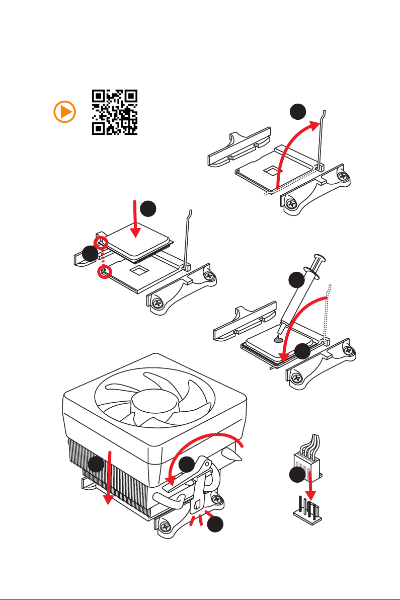
Installing a Processor/ Installation des Prozessors/ Installer un
processeur/ Установка процессора
1
https://youtu.be/Xv89nhFk1vc
3
2
5
Quick Start
II
4
6
8
9
7
Page 3
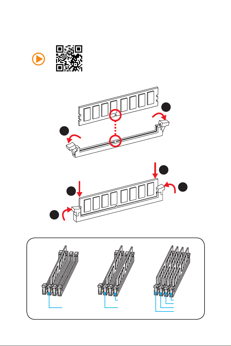
Installing DDR4 memory/ Installation des DDR4-Speichers/
Installer une mémoire DDR4/ Установка памяти DDR4
http://youtu.be/T03aDrJPyQs
1
1
2
2
3
DIMMB2 DIMMB2
DIMMA2 DIMMA2 DIMMA2
3
DIMMB1
DIMMA1
Quick Start
III
Page 4
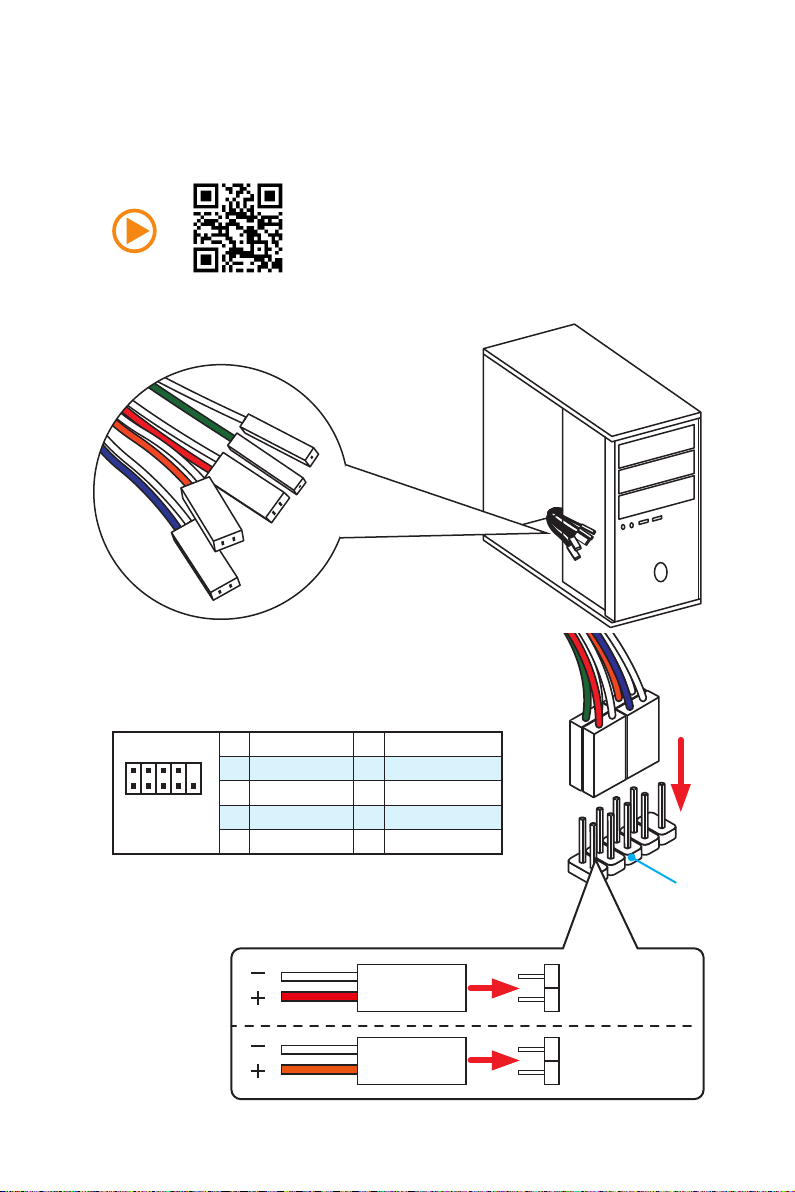
RESET SW
POWER SW
POWER LED+
POWER LED-
HDD LED
Connecting the Front Panel Header/ Anschließen der
Frontpanel-Stiftleiste/ Connecter un connecteur du panneau
avant/ Подключение разъемов передней панели
http://youtu.be/DPELIdVNZUI
IV
2 10
1
Quick Start
JFP1
1 HDD LED + 2 Power LED +
3 HDD LED - 4 Power LED -
5 Reset Switch 6 Power Switch
9
7 Reset Switch 8 Power Switch
9 Reserved 10 No Pin
HDD LED
POWER LED
RESET SW
HDD LED
JFP1
HDD LED HDD LED +
POWER LED POWER LED +
Page 5
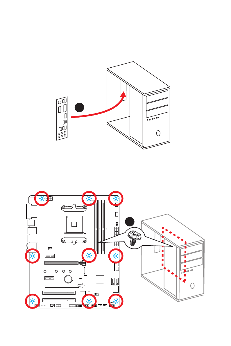
Installing the Motherboard/ Installation des Motherboards/
Installer la carte mère/ Установка материнской платы
1
2
BAT1
Quick Start
V
Page 6
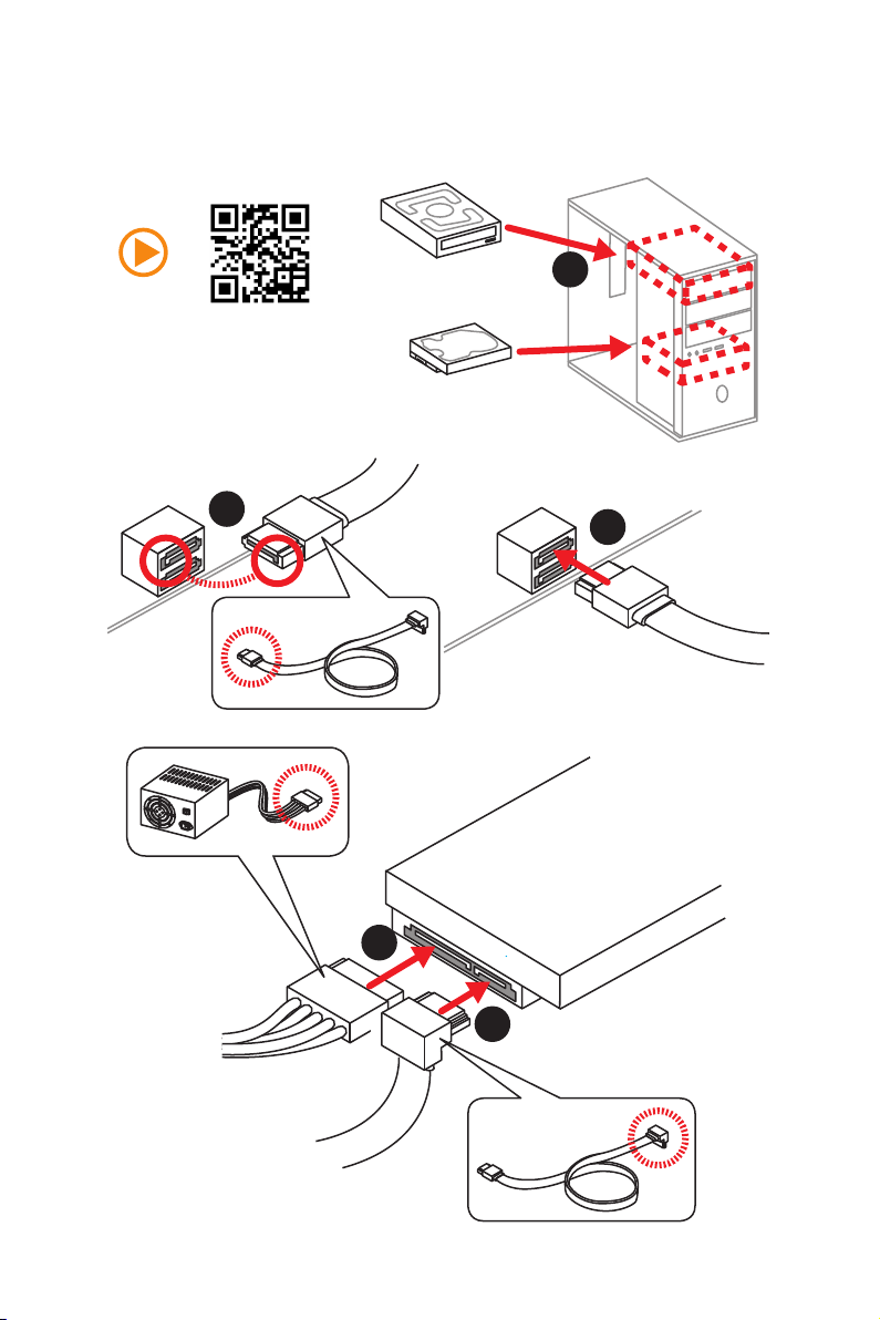
Installing SATA Drives/ Installation der SATA-Laufwerke/
Installer le disque dur SATA/ Установка дисков SATA
1
http://youtu.be/RZsMpqxythc
2
3
5
4
VI
Quick Start
Page 7
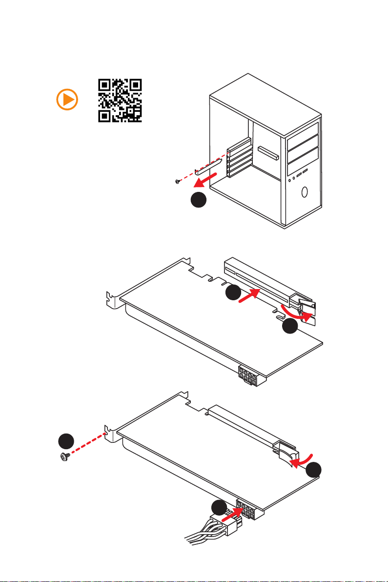
Installing a Graphics Card/ Einbau der Grafikkarte/ Installer
une carte graphique/ Установка дискретной видеокарты
http://youtu.be/mG0GZpr9w_A
1
3
2
5
4
6
Quick Start
VII
Page 8
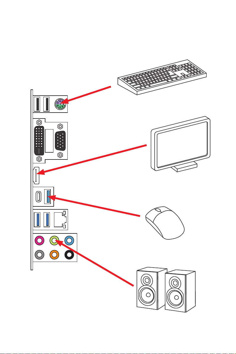
Connecting Peripheral Devices/ Peripheriegeräte/
Connecter un périphérique anschliessen/ Подключение
периферийных устройств
(7th Gen A-series/ Athlon™ processor)
VIII
Quick Start
Page 9
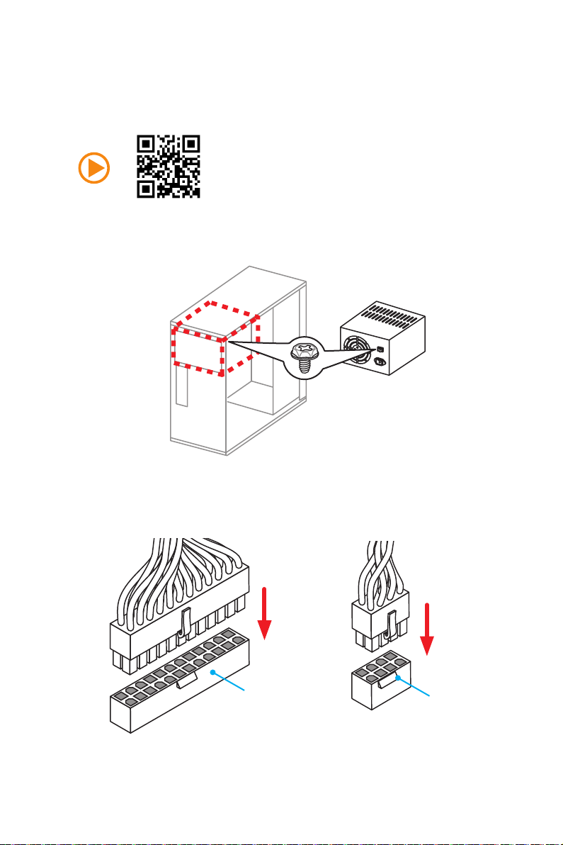
Connecting the Power Connectors/ Stromanschlüsse
anschliessen/ Connecter les câbles du module d’alimentation/
Подключение разъемов питания
http://youtu.be/gkDYyR_83I4
ATX_PWR1
CPU_PWR1
Quick Start
IX
Page 10
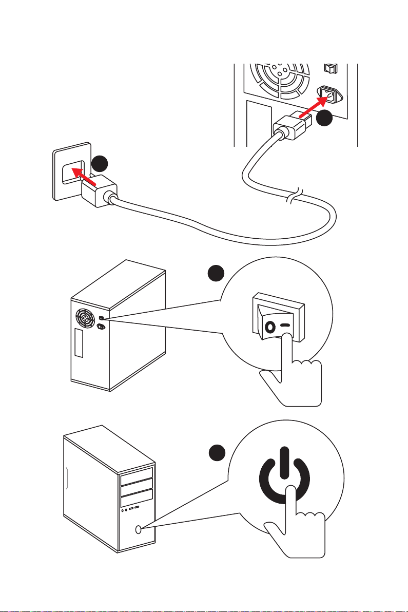
Power On/ Einschalten/ Mettre sous-tension/ Включение
питания
1
2
3
Quick Start
X
4
Page 11

Contents
Safety Information ................................................................................................. 2
Specifications ......................................................................................................... 3
Rear I/O Panel ....................................................................................................... 6
LAN Port LED Status Table..................................................................................... 6
Audio Ports Configuration ...................................................................................... 6
Realtek HD Audio Manager .................................................................................... 7
Overview of Components ...................................................................................... 9
CPU Socket ........................................................................................................... 10
DIMM Slots ............................................................................................................ 11
PCI_E1~4, PCI1~2: PCIe & PCI Expansion Slots .................................................. 12
M2_1: M.2 Slot (Key M) ......................................................................................... 13
SATA1~4: SATA 6Gb/s Connectors ....................................................................... 14
JAUD1: Front Audio Connector ............................................................................14
CPU_PWR1, ATX_PWR1: Power Connectors ....................................................... 15
JUSB1~2: USB 2.0 Connectors ............................................................................. 16
JUSB3~4: USB 3.1 Gen1 Connectors ................................................................... 16
CPU_FAN1, PUMP_FAN1, SYS_FAN1~4: Fan Connectors ................................... 17
JCI1: Chassis Intrusion Connector ....................................................................... 18
JLPT1: Parallel Port Connector ........................................................................... 18
JFP1, JFP2: Front Panel Connectors ................................................................... 19
JTPM1: TPM Module Connector ........................................................................... 19
JCOM1: Serial Port Connector ............................................................................. 19
JLED1: RGB LED strip connector ......................................................................... 20
JBAT1: Clear CMOS (Reset BIOS) Jumper ........................................................... 21
EZ Debug LEDs ..................................................................................................... 21
GPU LED ............................................................................................................... 21
BIOS Setup ........................................................................................................... 22
Entering BIOS Setup ............................................................................................. 22
Resetting BIOS ...................................................................................................... 23
Updating BIOS ....................................................................................................... 23
EZ Mode ................................................................................................................ 24
Advanced Mode .................................................................................................... 26
OC Menu................................................................................................................ 27
Software Description ........................................................................................... 30
Installing Windows® 7 64-bit/ Windows®10 64-bit ............................................... 30
Installing Drivers .................................................................................................. 30
Installing Utilities ................................................................................................. 30
Contents
1
Page 12

Safety Information
y The components included in this package are prone to damage from electrostatic
discharge (ESD). Please adhere to the following instructions to ensure successful
computer assembly.
y Ensure that all components are securely connected. Loose connections may cause
the computer to not recognize a component or fail to start.
y Hold the motherboard by the edges to avoid touching sensitive components.
y It is recommended to wear an electrostatic discharge (ESD) wrist strap when
handling the motherboard to prevent electrostatic damage. If an ESD wrist strap
is not available, discharge yourself of static electricity by touching another metal
object before handling the motherboard.
y Store the motherboard in an electrostatic shielding container or on an anti-static
pad whenever the motherboard is not installed.
y Before turning on the computer, ensure that there are no loose screws or metal
components on the motherboard or anywhere within the computer case.
y Do not boot the computer before installation is completed. This could cause
permanent damage to the components as well as injury to the user.
y If you need help during any installation step, please consult a certified computer
technician.
y Always turn off the power supply and unplug the power cord from the power outlet
before installing or removing any computer component.
y Keep this user guide for future reference.
y Keep this motherboard away from humidity.
y Make sure that your electrical outlet provides the same voltage as is indicated on
the PSU, before connecting the PSU to the electrical outlet.
y Place the power cord such a way that people can not step on it. Do not place
anything over the power cord.
y All cautions and warnings on the motherboard should be noted.
y If any of the following situations arises, get the motherboard checked by service
personnel:
Liquid has penetrated into the computer.
The motherboard has been exposed to moisture.
The motherboard does not work well or you can not get it work according to user
guide.
The motherboard has been dropped and damaged.
The motherboard has obvious sign of breakage.
y Do not leave this motherboard in an environment above 60°C (140°F), it may damage
the motherboard.
Safety Information
2
Page 13
Specifications
®
CPU
Chipset AMD
Supports AMD
A-series/ Athlon™ processors for Socket AM4
®
B350 Chipset
y4x DDR4 memory slots, support up to 64GB
Support DDR4 1866/ 2133/ 2400/ 2667(OC)/ 2933(OC)/
Memory
3200(OC)+ Mhz*
yDual channel memory architecture
* 7th Gen A-series/ Athlon ™ processors only support up to 2400 MHz. Please
refer www.msi.com for more information on compatible memory.
y 1x PCIe 3.0 x16 slot (PCI_E2)
Supports x 16 speed with RYZEN Series Processors
Supports x 8 speed with 7th Gen A-series/ Athlon™
processors
Expansion Slots
y 1x PCIe 2.0 x16 slot (PCI_E4, supports x4 mode)*
y 2x PCIe 2.0 x1 slots
y 2x PCI slots
* PCI_E4 slot will only support PCIe 2.0 x2 mode, when installing device in any
PCIe x1 slot.
Multi-GPU y Supports 2-Way AMD® CrossFire™ Technology
y 1x VGA port, supports a maximum resolution of
2048x1280@60HZ (RB)*
y 1x DVI-D port, supports a maximum resolution of
Onboard Graphics
1920x1200@60Hz*
y 1x HDMI™ port, supports a maximum resolution of
4096x2160@24Hz*
* Only support when using a 7th Gen A-series/ Athlon™ processor
®
AMD
B350 Chipset
y 4x SATA 6Gb/s ports*
Support RAID 0, RAID 1 and RAID 10
Storage
y 1x M.2 port (Key M)
Supports PCIe 3.0 x4 (RYZEN Series Processors) or PCIe
3.0 x2 (7th Gen A-series/ Athlon™ processors ) and SATA
6Gb/s
Suprts 2242/ 2260 /2280/ 22110 storage devices
Audio
y Realtek
y 7.1-Channel High Definition Audio
LAN y 1x Realtek
RYZEN series processors and 7th Gen
®
ALC892 Codec
®
8111H Gigabit LAN controller
Continued on next page
Specifications
3
Page 14

Continued from previous page
®
y AMD
B350 Chipset
4x USB 3.1 Gen1 (SuperSpeed USB) ports available
through the internal USB 3.1 Gen1 connectors
6x USB 2.0 (High-speed USB) ports (2 Type-A ports on
USB
the back panel, 4 ports available through the internal
USB 2.0 connectors)
®
y AMD
processor
4x USB 3.1 Gen1 (SuperSpeed USB) ports (3 Type-A
ports and 1 Type-C port on the back panel)
y 1x PS/2 keyboard/ mouse combo port
y 2x USB 2.0 Type-A ports
y 1x VGA port
Back Panel
Connectors
y 1x DVI-D port
y 1x HDMI
™
port
y 3x USB 3.1 Gen1 Type-A ports
y 1x USB 3.1 Gen1 Type-C port
y 1x LAN (RJ45) port
y 6x audio jacks
y 1x 24-pin ATX main power connector
y 1x 8-pin ATX 12V power connector
y 4x SATA 6Gb/s connectors
y 2x USB 2.0 connectors (support additional 4 USB 2.0 ports)
y 2x USB 3.1 Gen1 connectors (support additional 4 USB 3.1
Gen1 ports)
y 1x 4-pin CPU fan connector
y 1x 4-pin water-pump-fan connector
Internal Connectors
y 4x 4-pin system fan connectors
y 1x 4-pin RGB LED strip connector
y 1x Serial port connector
y 1x Parallel port connector
y 1x TPM module connector
y 1x Front panel audio connector
y 2x System panel connectors
y 1x Chassis Intrusion connector
y 1x Clear CMOS jumper
I/O Controller NUVOTON NCT6795D Controller Chip
Specifications
4
Continued on next page
Page 15

Hardware Monitor
Form Factor
BIOS Features
Software
Special Features
Continued from previous page
y CPU/System temperature detection
y CPU/System fan speed detection
y CPU/System fan speed control
y ATX Form Factor
y 12 in. x 9.6 in. (30.4 cm x 24.3 cm)
y 1x 128 Mb flash
y UEFI AMI BIOS
y Multi-language
y Drivers
y SUPER CHARGER
y COMMAND CENTER
y LIVE UPDATE 6
y MSI SMART TOOL
y MYSTIC LIGHT
y X-BOOST
y RAMDISK
y NETWORK GENIE
y CPU-Z MSI GAMING
y Google Chrome
y Norton
™
™
Internet Security Solution
,Google Toolbar, Google Drive
y Audio Boost
y Turbo M.2
y Pump Fan
y Smart Fan Control
y Mystic Light Extension
y Mystic light SYNC
y EZ DEBUG LED
y PCI-E Steel Armor
y DDR4 Boost
y Lightning USB
y Military Class 4
y 7000+ Quality Test
y VR Ready
y Click BIOS 5
y AMD FreeSync™ Ready
y AMD OverDriver™ Ready
Specifications
5
Page 16
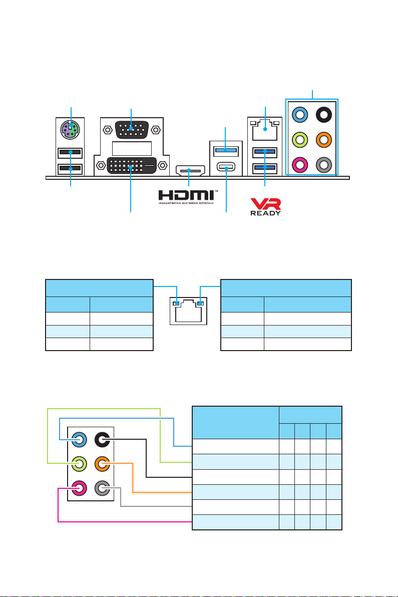
Rear I/O Panel
PS/2 LAN
VGA
USB 3.1 Gen1
Audio Ports
USB 2.0
DVI-D
LAN Port LED Status Table
Link/ Activity LED
Status Description
Off No link
Yellow Linked
Blinking Data activity
Audio Ports Configuration
USB 3.1 Gen1
USB 3.1 Gen1
Type-C
Speed LED
Status Description
Off 10 Mbps connection
Green 100 Mbps connection
Orange 1 Gbps connection
Audio Ports
Line-In
Line-Out/ Front Speaker Out ● ● ● ●
Rear Speaker Out ● ● ●
Center/ Subwoofer Out ● ●
Side Speaker Out ●
Mic In
Channel
2 4 6 8
(●: connected, Blank: empty)
Rear I/O Panel
6
Page 17
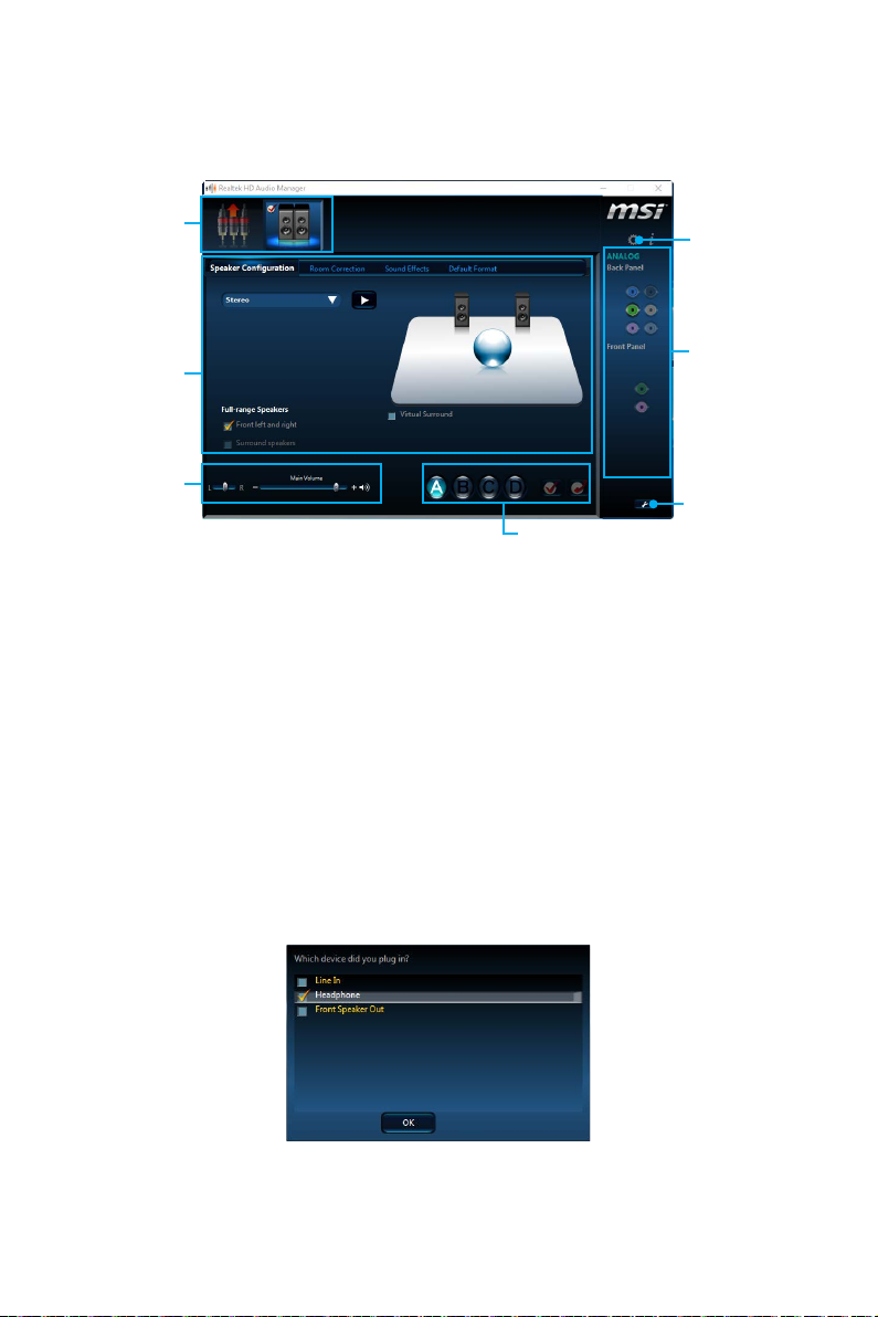
Realtek HD Audio Manager
After installing the Realtek HD Audio driver, the Realtek HD Audio Manager icon will
appear in the system tray. Double click on the icon to launch.
Device
Selection
Advanced
Settings
Application
Enhancement
Main Volume
Profiles
Jack Status
Connector
Strings
y Device Selection - allows you to select a audio output source to change the related
options. The check sign indicates the devices as default.
y Application Enhancement - the array of options will provide you a complete
guidance of anticipated sound effect for both output and input device.
y Main Volume - controls the volume or balance the right/left side of the speakers
that you plugged in front or rear panel by adjust the bar.
y Profiles - toggles between profiles.
y Advanced Settings - provides the mechanism to deal with 2 independent audio
streams.
y Jack Status - depicts all render and capture devices currently connected with your
computer.
y Connector Settings - configures the connection settings.
Auto popup dialog
When you plug into a device at an audio jack, a dialogue window will pop up asking you
which device is current connected.
Each jack corresponds to its default setting as shown on the next page.
Rear I/O Panel
7
Page 18
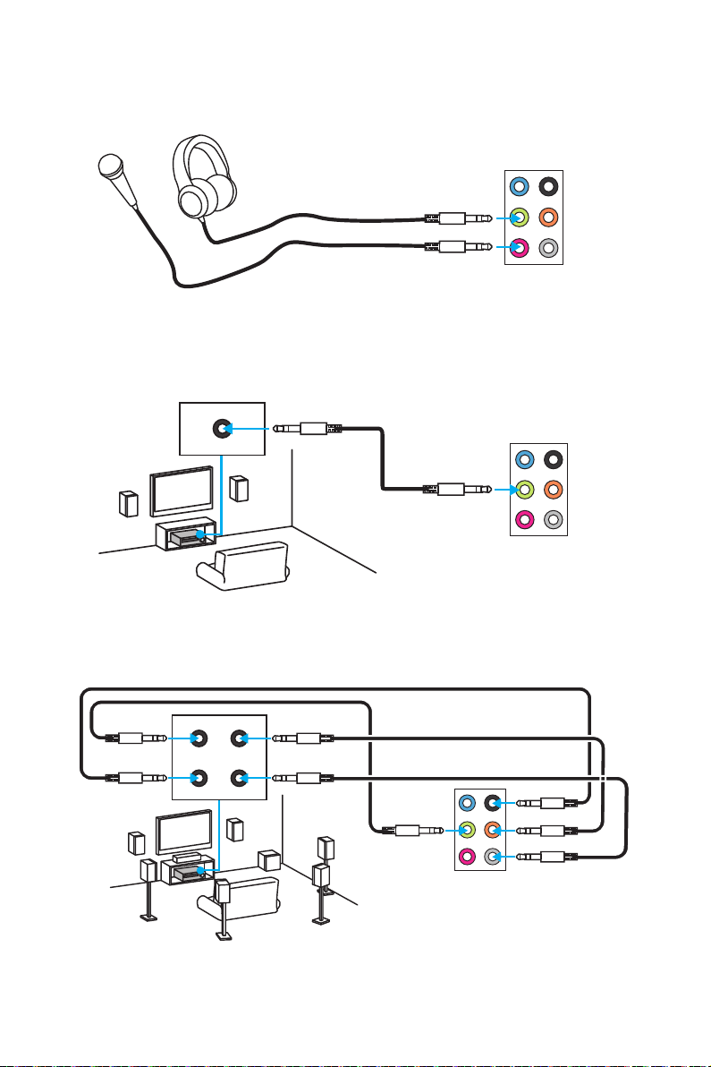
Audio jacks to headphone and microphone diagram
Audio jacks to stereo speakers diagram
AUDIO INPUT
Audio jacks to 7.1-channel speakers diagram
AUDIO INPUT
Front
Center/
Subwoofer
Side
Rear
Rear I/O Panel
8
Page 19
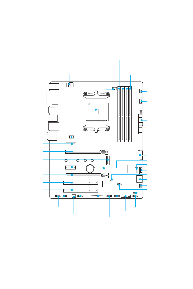
Overview of Components
PCI_E1
PCI_E2
M2_1
PCI_E3
PCI_E4
PCI1
PCI2
CPU_PWR1
SYS_FAN1
CPU Socket
BAT1
CPU_FAN1
DIMMA1
DIMMA2
DIMMB1
DIMMB2
PUMP_FAN1
SYS_FAN3
ATX_PWR1
JUSB4
JBAT1
SATA4
SATA3
JCI1
SATA▼1▲2
SYS_FAN4
JTPM1
JFP2
JAUD1
JLED1
SYS_FAN2
JCOM1
JLPT1
JUSB1
JUSB2
JFP1
JUSB3
Overview of Components
9
Page 20
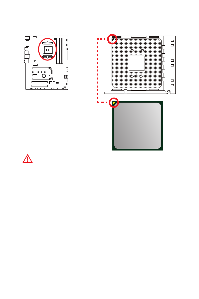
CPU Socket
Introduction to the AM4 CPU
The surface of the AM4 CPU has a
yellow triangle to assist in correctly
lining up the CPU for motherboard
placement. The yellow triangle is
the Pin 1 indicator.
Important
y
When changing the processor, the system configuration could be cleared and reset
BIOS to default values, due to the AM4 processor’s architecture.
y
Always unplug the power cord from the power outlet before installing or removing
the CPU.
y
When installing a CPU, always remember to install a CPU heatsink. A CPU heatsink
is necessary to prevent overheating and maintain system stability.
y
Confirm that the CPU heatsink has formed a tight seal with the CPU before booting
your system.
y
Overheating can seriously damage the CPU and motherboard. Always make sure
the cooling fans work properly to protect the CPU from overheating. Be sure to
apply an even layer of thermal paste (or thermal tape) between the CPU and the
heatsink to enhance heat dissipation.
y
If you purchased a separate CPU and heatsink/ cooler, Please refer to the
documentation in the heatsink/ cooler package for more details about installation.
y
This motherboard is designed to support overclocking. Before attempting to
overclock, please make sure that all other system components can tolerate
overclocking. Any attempt to operate beyond product specifications is not
recommended. MSI® does not guarantee the damages or risks caused by
inadequate operation beyond product specifications.
Overview of Components
10
Page 21
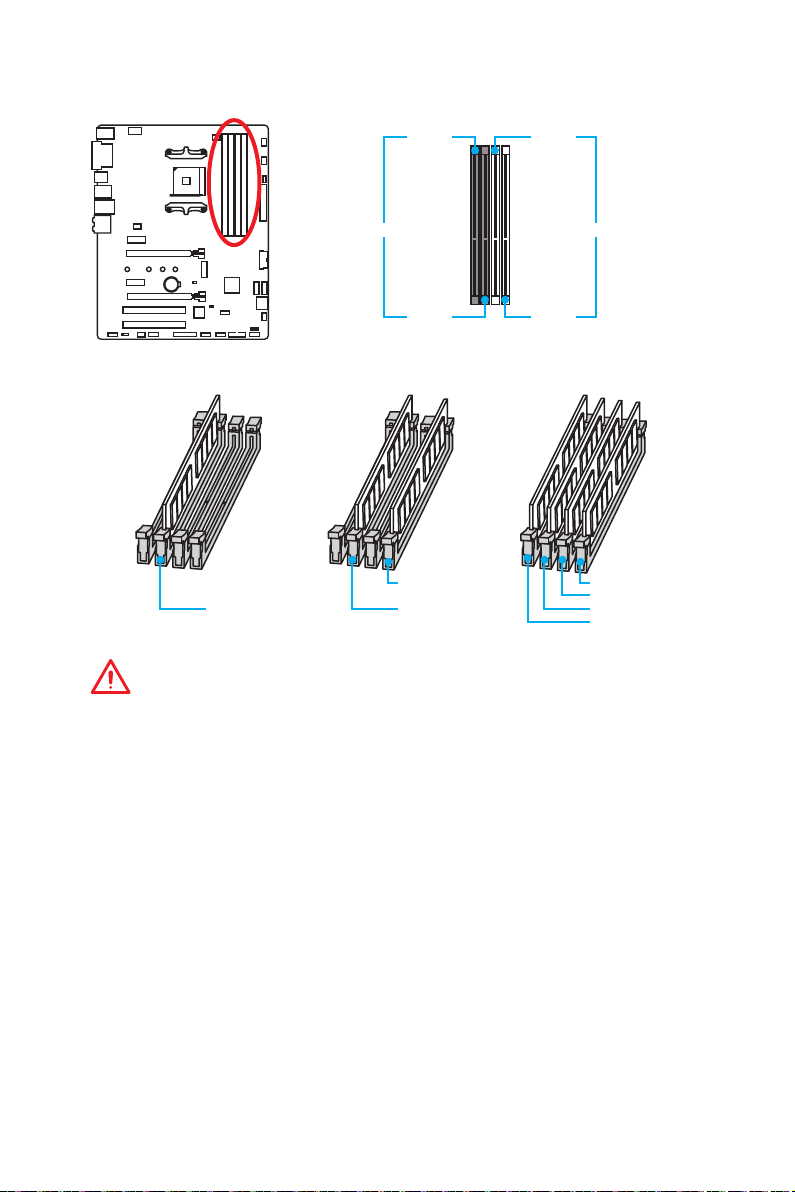
DIMM Slots
DIMMA1 DIMMB1
Channel A Channel B
DIMMA2 DIMMB2
Memory module installation recommendation
DIMMB2 DIMMB2
DIMMA2 DIMMA2 DIMMA2
DIMMB1
DIMMA1
Important
y
Always insert memory modules in the DIMMA2 slot first.
y
Due to chipset resource usage, the available capacity of memory will be a little less
than the amount of installed.
y
Based on processor specification, the Memory DIMM voltage below 1.35V is
suggested to protect the processor.
y
Some memory modules may operate at a lower frequency than the marked value
when overclocking due to the memory frequency operates dependent on its Serial
Presence Detect (SPD). Go to BIOS and find the DRAM Frequency! to set the
memory frequency if you want to operate the memory at the marked or at a higher
frequency.
y
It is recommended to use a more efficient memory cooling system for full DIMMs
installation or overclocking.
y
The stability and compatibility of installed memory module depend on installed
processor and devices when overclocking.
y
Due to AM4 CPU/memory controller official specification limitation, the frequency of
memory modules may operate lower than the marked value under the default state.
Please refer www.msi.com for more information on compatible memory.
Overview of Components
11
Page 22
PCI_E1~4, PCI1~2: PCIe & PCI Expansion Slots
PCI_E1: PCIe 2.0 x1
PCI_E2: PCIe 3.0 x16 (RYZEN Series processors)
PCIe 3.0 x8 (7th Gen A-series/ Athlon™
BAT1
PCI_E3: PCIe 2.0 x1
PCI_E4: PCIe 2.0 x4
PCI1: PCI slot
PCI2: PCI slot
Important
y
If you install a large and heavy graphics card, you need to use a tool such as MSI
Gaming Series Graphics Card Bolster to support its weight to prevent deformation
of the slot.
y
For a single PCIe x16 expansion card installation with optimum performance, using
the PCI_E2 slot is recommended.
y
When adding or removing expansion cards, always turn off the power supply and
unplug the power supply power cable from the power outlet. Read the expansion
card’s documentation to check for any necessary additional hardware or software
changes.
y
Only when both PCIe x1 slots are empty, this motherboard could support AMD®
CrossFire™ technology.
PCIe bandwidth table
For RYZEN series processors
processors)
Slot Bandwidth
PCI_E1 Empty 2.0 x1 Empty 2.0 x1
PCI_E2 3.0 x16 3.0 x16 3.0 x16 3.0 x16
PCI_E3 Empty Empty 2.0 x1 2.0 x1
PCI_E4 2.0 x4 2.0 x2 2.0 x2 2.0 x2
M2_1 3.0 x4 3.0 x4 3.0 x4 3.0 x4
For 7th Gen A-series/ Athlon™ processors
Slot Bandwidth
PCI_E1 Empty 2.0 x1 Empty 2.0 x1
PCI_E2 3.0 x8 3.0 x8 3.0 x8 3.0 x8
PCI_E3 Empty Empty 2.0 x1 2.0 x1
PCI_E4 2.0 x4 2.0 x2 2.0 x2 2.0 x2
M2_1 3.0 x2 3.0 x2 3.0 x2 3.0 x2
Overview of Components
12
Page 23

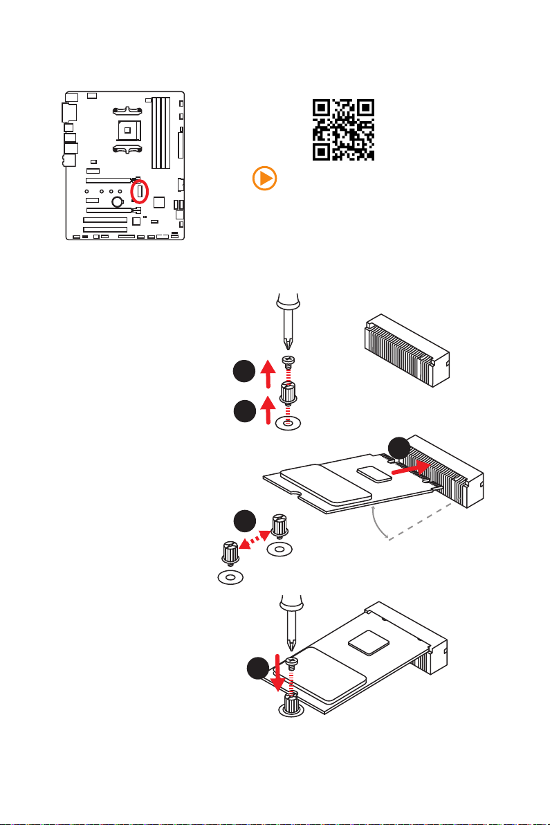
M2_1: M.2 Slot (Key M)
Installing M.2 module
1. Remove the screw from
the base screw.
2. Remove the base screw.
Video Demonstration
Watch the video to learn how to Install M.2
module.
http://youtu.be/JCTFABytrYA
1
2
3. Tighten the base screw
into the hole of the
distance to the M.2 slot
as the length your M.2
module.
4. Insert your M.2 module
into the M.2 slot at a
30-degree angle.
5. Put the screw in the
notch on the trailing edge
of your M.2 module and
tighten it into the base
screw.
4
3
30°
5
Overview of Components
13
Page 24
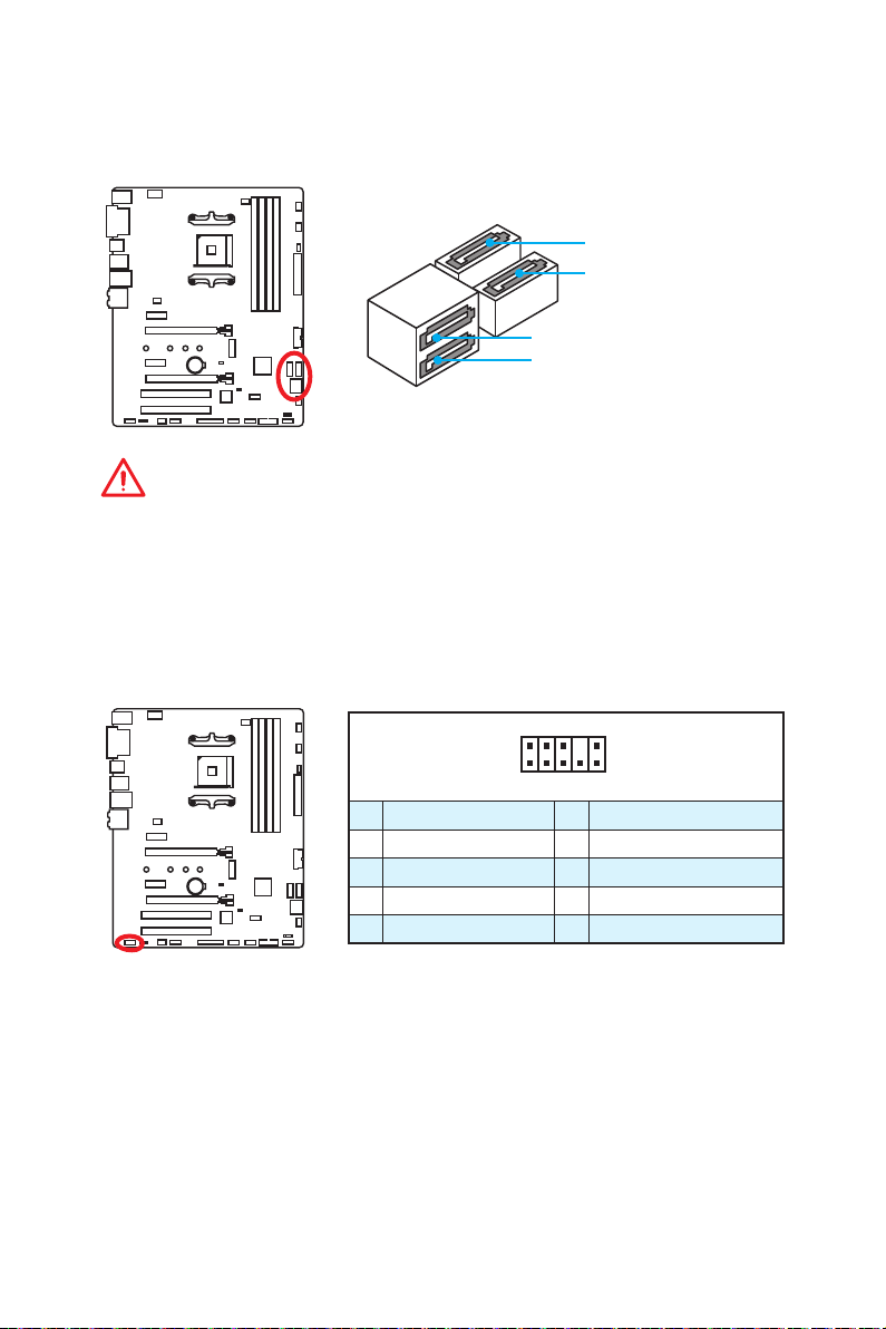
SATA1~4: SATA 6Gb/s Connectors
These connectors are SATA 6Gb/s interface ports. Each connector can connect to one
SATA device.
SATA4
SATA3
SATA2
SATA1
Important
y
Please do not fold the SATA cable at a 90-degree angle. Data loss may result during
transmission otherwise.
y
SATA cables have identical plugs on either sides of the cable. However, it is
recommended that the flat connector be connected to the motherboard for space
saving purposes.
JAUD1: Front Audio Connector
This connector allows you to connect audio jacks on the front panel.
2 10
Overview of Components
14
1
9
1 MIC L 2 Ground
3 MIC R 4 NC
5 Head Phone R 6 MIC Detection
7 SENSE_SEND 8 No Pin
9 Head Phone L 10 Head Phone Detection
Page 25
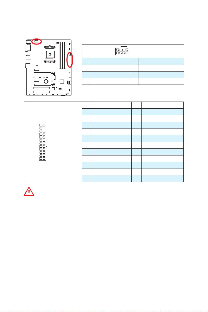
CPU_PWR1, ATX_PWR1: Power Connectors
These connectors allow you to connect an ATX power supply.
8
4 1
1 Ground 5 +12V
2 Ground 6 +12V
3 Ground 7 +12V
4 Ground 8 +12V
1 +3.3V 13 +3.3V
2 +3.3V 14 -12V
3 Ground 15 Ground
24
12
ATX_PWR1
131
4 +5V 16 PS-ON#
5 Ground 17 Ground
6 +5V 18 Ground
7 Ground 19 Ground
8 PWR OK 20 Res
9 5VSB 21 +5V
10 +12V 22 +5V
11 +12V 23 +5V
12 +3.3V 24 Ground
5
CPU_PWR1
Important
Make sure that all the power cables are securely connected to a proper ATX power
supply to ensure stable operation of the motherboard.
Overview of Components
15
Page 26
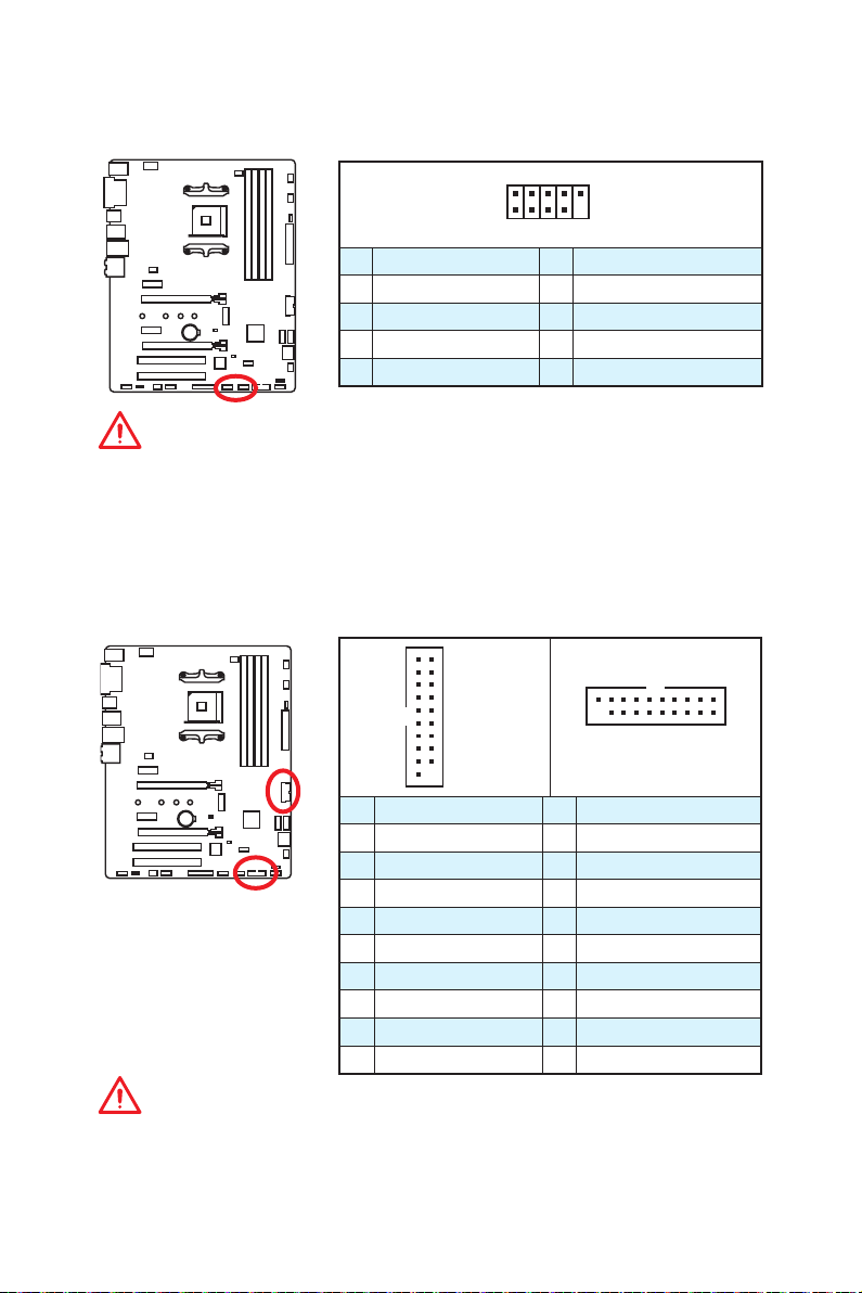
JUSB1~2: USB 2.0 Connectors
These connectors allow you to connect USB 2.0 ports on the front panel.
2 10
1
9
1 VCC 2 VCC
3 USB0- 4 USB1-
5 USB0+ 6 USB1+
7 Ground 8 Ground
9 No Pin 10 NC
Important
y
Note that the VCC and Ground pins must be connected correctly to avoid possible
damage.
y
In order to recharge your iPad,iPhone and iPod through USB ports, please install
MSI® SUPER CHARGER utility.
JUSB3~4: USB 3.1 Gen1 Connectors
These connectors allow you to connect USB 3.1 Gen1 ports on the front panel.
10 11
JUSB4
1
20
1 Power 11 USB2.0+
2 USB3_RX_DN 12 USB2.0-
3 USB3_RX_DP 13 Ground
4 Ground 14 USB3_TX_C_DP
5 USB3_TX_C_DN 15 USB3_TX_C_DN
6 USB3_TX_C_DP 16 Ground
7 Ground 17 USB3_RX_DP
8 USB2.0- 18 USB3_RX_DN
9 USB2.0+ 19 Power
10 NC 20 No Pin
1
20
JUSB3
Important
Note that the Power and Ground pins must be connected correctly to avoid possible
damage.
Overview of Components
16
10
11
Page 27
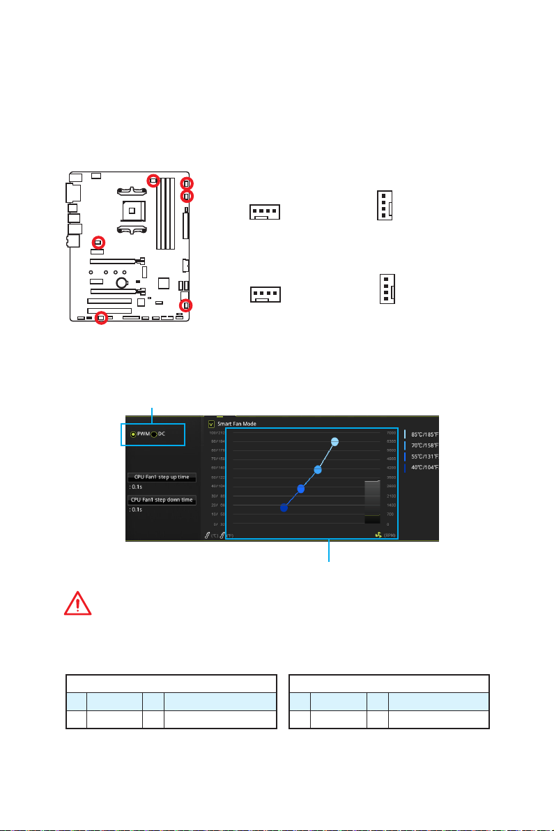
CPU_FAN1, PUMP_FAN1, SYS_FAN1~4: Fan Connectors
Fan connectors can be classified as PWM (Pulse Width Modulation) Mode or DC Mode.
PWM Mode fan connectors provide constant 12V output and adjust fan speed with
speed control signal. DC Mode fan connectors control fan speed by changing voltage.
When you plug a 3-pin (Non-PWM) fan to a fan connector in PWM mode, the fan speed
will always maintain at 100%, which might create a lot of noise. You can follow the
instruction below to adjust the fan connector to PWM or DC Mode.
Default PWM Mode fan connectors
1
CPU_FAN1
Default DC Mode fan connectors
1
SYS_FAN1/ SYS_FAN2
Switching fan mode and adjusting fan speed
You can switch between PWM mode and DC mode and adjust fan speed in BIOS >
HARDWARE MONITOR.
Select PWM mode or DC mode
1
PUMP_FAN1
1
SYS_FAN3/ SYS_FAN4
There are gradient points of the fan speed that allow you to adjust
fan speed in relation to CPU temperature.
Important
Make sure fans are working properly after switching the PWM/ DC mode.
Pin definition of fan connectors
PWM Mode pin definition
1 Ground 2 +12V
3 Sense 4 Speed Control Signal
1 Ground 2 Voltage Control
3 Sense 4 NC
DC Mode pin definition
Overview of Components
17
Page 28
JCI1: Chassis Intrusion Connector
This connector allows you to connect the chassis intrusion switch cable.
Normal
(default)
Trigger the chassis
intrusion event
Using chassis intrusion detector
1. Connect the JCI1 connector to the chassis intrusion switch/ sensor on the chassis.
2. Close the chassis cover.
3. Go to BIOS > SETTINGS > Security > Chassis Intrusion Configuration.
4. Set Chassis Intrusion to Enabled.
5. Press F10 to save and exit and then press the Enter key to select Yes.
6. Once the chassis cover is opened again, a warning message will be displayed on
screen when the computer is turned on.
Resetting the chassis intrusion warning
1. Go to BIOS > SETTINGS > Security > Chassis Intrusion Configuration.
2. Set Chassis Intrusion to Reset.
3. Press F10 to save and exit and then press the Enter key to select Yes.
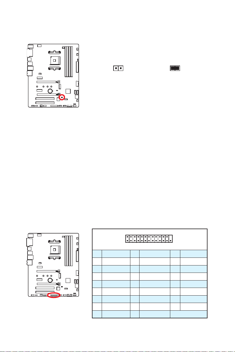
JLPT1: Parallel Port Connector
This connector allows you to connect the optional parallel port with bracket.
2 26
1
1 RSTB# 2 AFD# 3 PRND0
4 ERR# 5 PRND1 6 PINIT#
7 PRND2 8 LPT_SLIN# 9 PRND3
10 Ground 11 PRND4 12 Ground
13 PRND5 14 Ground 15 PRND6
16 Ground 17 PRND7 18 Ground
19 ACK# 20 Ground 21 BUSY
22 Ground 23 PE 24 Ground
25 SLCT 26 No Pin
25
Overview of Components
18
Page 29
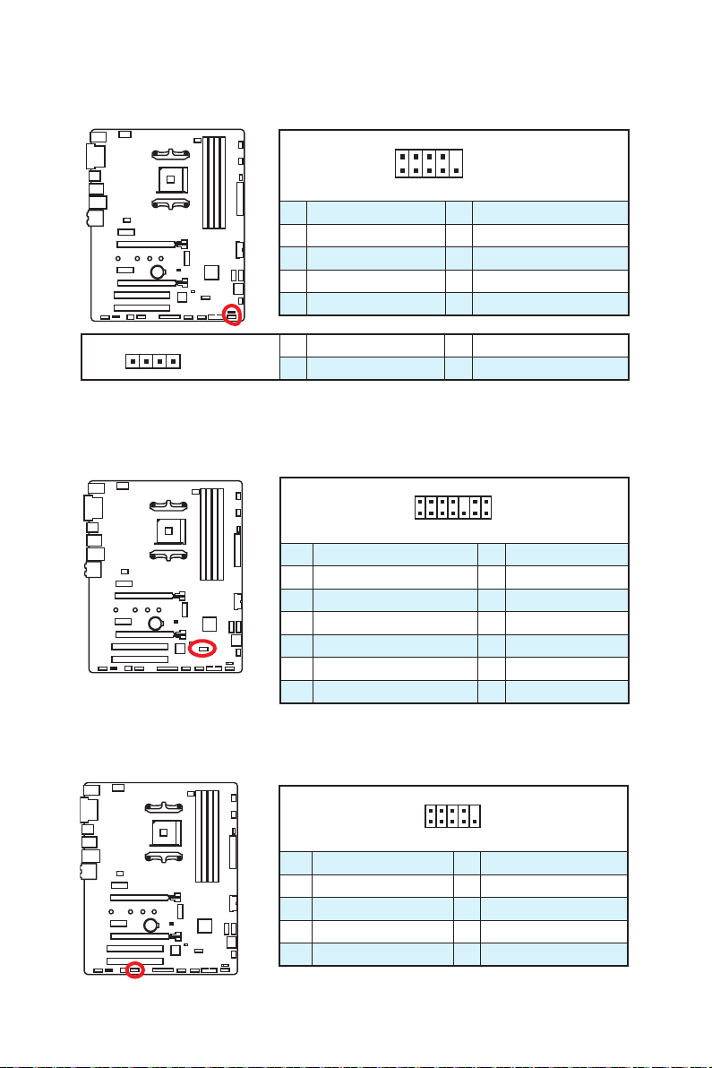
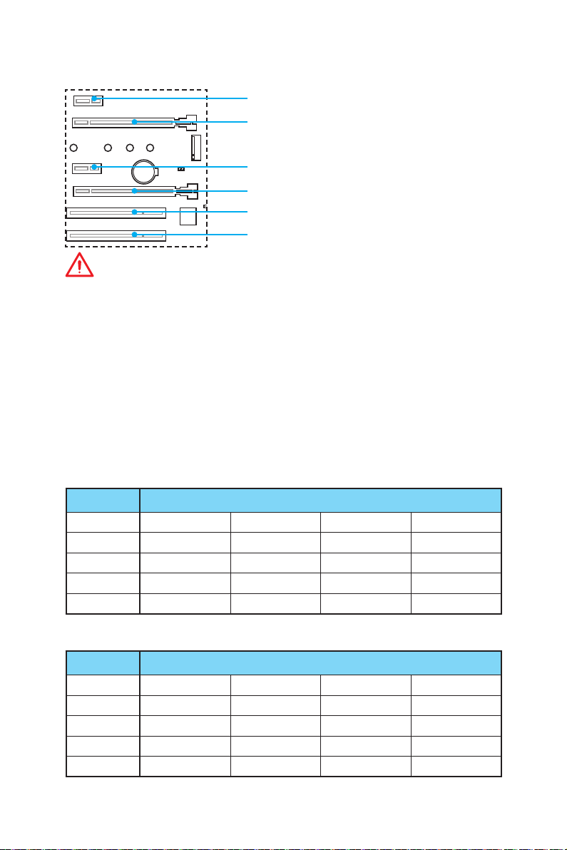
JFP1, JFP2: Front Panel Connectors
These connectors connect to the switches and LEDs on the front panel.
2 10
JFP1
1
9
1 HDD LED + 2 Power LED +
3 HDD LED - 4 Power LED -
5 Reset Switch 6 Power Switch
7 Reset Switch 8 Power Switch
9 Reserved 10 No Pin
1
JFP2
1 Speaker - 2 Buzzer +
3 Buzzer - 4 Speaker +
JTPM1: TPM Module Connector
This connector is for TPM (Trusted Platform Module). Please refer to the TPM security
platform manual for more details and usages.
2 14
1
1 LPC Clock 2 3V Standby power
3 LPC Reset 4 3.3V Power
5 LPC address & data pin0 6 Serial IRQ
7 LPC address & data pin1 8 5V Power
9 LPC address & data pin2 10 No Pin
11 LPC address & data pin3 12 Ground
13 LPC Frame 14 Ground
13
JCOM1: Serial Port Connector
This connector allows you to connect the optional serial port with bracket.
2 10
1
9
1 DCD 2 SIN
3 SOUT 4 DTR
5 Ground 6 DSR
7 RTS 8 CTS
9 RI 10 No Pin
Overview of Components
19
Page 30
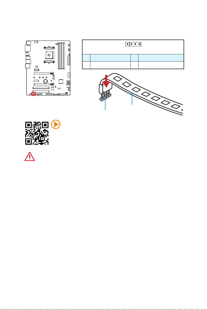
JLED1: RGB LED strip connector
This connector allows you to connect the extended 5050 RGB LED strips.
1
1 +12V 2 G
3 R 4 B
1
JLED1
Video Demonstration
Watch the video to learn how to install 5050 RGB LED strips to RGB LED
connector.
https://youtu.be/CqNHyADzd2Q
Important
y
This connector supports 5050 RGB multi-color LED strips (12V/G/R/B) with the
maximum power rating of 3A (12V). Please keeping the LED strip shorter than 2
meters to prevent dimming.
y
Always turn off the power supply and unplug the power cord from the power outlet
before installing or removing the RGB LED strip.
y
Please use MYSTIC LIGHT to control the extended LED strip
5050 LED strip
Overview of Components
20
Page 31

JBAT1: Clear CMOS (Reset BIOS) Jumper
There is CMOS memory onboard that is external powered from a battery located on
the motherboard to save system configuration data. If you want to clear the system
configuration, set the jumpers to clear the CMOS memory.
Keep Data
(default)
Clear CMOS/
Reset BIOS
Resetting BIOS to default values
1. Power off the computer but DO NOT unplug the power cord (system under S5/
Soft-off mode).
2. Use a jumper cap to short JBAT1 for about 5-10 seconds.
3. Remove the jumper cap from JBAT1.
4. Power on the computer.
EZ Debug LEDs
These LEDs indicate the status of key components during booting process. When an
error is occurred, the corresponding LED stays lit until the problem is solved.
CPU - indicates CPU is not detected or fail.
DRAM - indicates DRAM is not detected or fail.
VGA - indicates GPU is not detected or fail.
BOOT - indicates the booting device is not detected or fail.
GPU LED
This LED indicates the CPU’s iGPU is not detected and you need to install a graphic
card.
GPU LED
EZ Debug LEDs
Overview of Components
21
Page 32

BIOS Setup
The default settings offer the optimal performance for system stability in normal
conditions. You should always keep the default settings to avoid possible system
damage or failure booting unless you are familiar with BIOS.
Important
y
BIOS items are continuously update for better system performance. Therefore,
the description may be slightly different from the latest BIOS and should be for
reference only. You could also refer to the HELP information panel for BIOS item
description.
y
The pictures in this chapter are for reference only and may vary from the product
you purchased.
y
The BIOS items will vary with the processor.
Entering BIOS Setup
Press Delete key, when the Press DEL key to enter Setup Menu, F11 to enter Boot
Menu message appears on the screen during the boot process.
Function key
F1: General Help list
F2: Add/ Remove a favorite item
F3: Enter Favorites menu
F4: Enter CPU Specifications menu
F5: Enter Memory-Z menu
F6: Load optimized defaults
F7: Switch between Advanced mode and EZ mode
F8: Load Overclocking Profile
F9: Save Overclocking Profile
F10: Save Change and Reset*
F12: Take a screenshot and save it to USB flash drive (FAT/ FAT32 format only).
* When you press F10, a confirmation window appears and it provides the modification
information. Select between Yes or No to confirm your choice.
22
BIOS Setup
Page 33

Resetting BIOS
You might need to restore the default BIOS setting to solve certain problems. There are
several ways to reset BIOS:
y Go to BIOS and press F6 to load optimized defaults.
y Short the Clear CMOS jumper on the motherboard.
Important
Be sure the computer is off before clearing CMOS data. Please refer to the Clear
CMOS jumper section for resetting BIOS.
Updating BIOS
Updating BIOS with M-FLASH
Before updating:
Please download the latest BIOS file that matches your motherboard model from MSI
website. And then save the BIOS file into the USB flash drive.
Updating BIOS:
1. Press Del key to enter the BIOS Setup during POST.
2. Insert the USB flash drive that contains the update file into the computer.
3. Select the M-FLASH tab and click on Yes to reboot the system and enter the flash
mode.
4. Select a BIOS file to perform the BIOS update process.
5. After the flashing process is 100% completed, the system will reboot
automatically.
Updating the BIOS with Live Update 6
Before updating:
Make sure the LAN driver is already installed and the internet connection is set
properly.
Updating BIOS:
1. Install and launch MSI LIVE UPDATE 6.
2. Select BIOS Update.
3. Click on Scan button.
4. Click on Download icon to download and install the latest BIOS file.
5. Click Next and choose In Windows mode. And then click Next and Start to start
updating BIOS.
6. After the flashing process is 100% completed, the system will restart
automatically.
BIOS Setup
23
Page 34

EZ Mode
At EZ mode, it provides the basic system information and allows you to configure the
basic setting. To configure the advanced BIOS settings, please enter the Advanced
Mode by pressing the Setup Mode switch or F7 function key.
Setup Mode switch
OC GENIE 4
switch
Information
display
M-Flash
Favorites
Hardware
Monitor
y OC GENIE 4 switch - click on it to toggle the OC GENIE 4 for OC.
Important
Please don’t make any changes in OC menu and don’t load defaults to keep the
optimal performance and system stability after activating the OC GENIE 4 function.
y Setup Mode switch - press this tab or the F7 key to switch between Advanced mode
and EZ mode.
y Screenshot - click on this tab or the F12 key to take a screenshot and save it to USB
flash drive (FAT/ FAT32 format only).
y Search - click on this tab or the Ctrl+F keys and the search page will show. It allows
you to search by BIOS item name, enter the item name to find the item listing. Move
the mouse over a blank space and right click the mouse to exit search page.
Screenshot
Search
Language
System
information
Boot device
priority bar
Function
buttons
Important
In search page, only the F6, F10 and F12 function keys are available.
y Language - allows you to select the language of BIOS setup.
y System information - shows the CPU/ DDR speed, CPU/ MB temperature, MB/ CPU
type, memory size, CPU/ DDR voltage, BIOS version and build date.
y Boot device priority bar - you can move the device icons to change the boot priority.
The boot priority from high to low is left to right.
BIOS Setup
24
Page 35

y Information display - click on the CPU, Memory, Storage, Fan Info and Help
buttons on left side to display related information.
y Function buttons - enable or disable the LAN Option ROM, HD audio controller,
AHCI, RAID, CPU Fan Fail Warning Control and BIOS Log Review by clicking on their
respective button.
y M-Flash - click on this button to display the M-Flash menu that provides the way to
update BIOS with a USB flash drive.
y Hardware Monitor - click on this button to display the Hardware Monitor menu that
allows you to manually control the fan speed by percentage.
y Favorites menu - press the F3 key to enter Favorites menu. It allows you to create
personal BIOS menu where you can save and access favorite/ frequently-used BIOS
setting items.
Default HomePage - allows you to select a BIOS menu (e.g. SETTINGS, OC...,etc)
as the BIOS home page.
Favorite1~5 - allows you to add the frequently-used/ favorite BIOS setting items in
one page.
To add a BIOS item to a favorite page (Favorite 1~5)
1. Move the mouse over a BIOS item not only on BIOS menu but also on search
page.
2. Right-click or press F2 key.
3. Choose a favorite page and click on OK.
To delete a BIOS item from favorite page
1. Move the mouse over a BIOS item on favorite page (Favorite 1~5)
2. Right-click or press F2 key.
3. Choose Delete and click on OK.
BIOS Setup
25
Page 36

Advanced Mode
Press Setup Mode switch or F7 function key can switch between EZ Mode and
Advanced Mode in BIOS setup.
OC GENIE 4
switch
BIOS menu
selection
Setup Mode switch
Menu display
Screenshot
Search
Language
System
information
Boot device
priority bar
BIOS menu
selection
y OC GENIE 4 switch/ Setup Mode switch/ Screenshot/ Language/ System
information/ Boot device priority bar - please refer to the descriptions of EZ Mode
Overview section.
y BIOS menu selection - the following options are available:
SETTINGS - allows you to specify the parameters for chipset and boot devices.
OC - allows you to adjust the frequency and voltage. Increasing the frequency may
get better performance.
M-FLASH - provides the way to update BIOS with a USB flash drive.
OC PROFILE - allows you to manage overclocking profiles.
HARDWARE MONITOR - allows you to set the speeds of fans and monitor voltages
of system.
BOARD EXPLORER - provides the information of installed devices on this
motherboard.
y Menu display - provides BIOS setting items and information to be configured.
26
BIOS Setup
Page 37

OC Menu
This menu is for advanced users who want to overclock the motherboard.
Important
y
Overclocking your PC manually is only recommended for advanced users.
y
Overclocking is not guaranteed, and if done improperly, it could void your warranty
or severely damage your hardware.
y
If you are unfamiliar with overclocking, we advise you to use OC GENIE 4 function for
easy overclocking.
f OC Explore Mode [Normal]
Enables or disables to show the normal or expert version of OC settings.
[Normal] Provides the regular OC settings in BIOS setup.
[Expert] Provides the advanced OC settings for OC expert to configure in BIOS
Note: We use * as the symbol for the OC settings of Expert mode.
f CPU Frequency [Auto]
Sets the CPU frequency.
f Core Performance Boost [Auto]
Enables or disables the Core Performance Boost (CPB). This item appears when the
installed CPU supports this function.
f Downcore Control [Auto] (optional)
Sets the number of processor cores to be used. This item appears when the installed
CPU supports this function.
f DRAM Frequency [Auto]
Sets the DRAM frequency. Please note the overclocking behavior is not guaranteed.
f Adjusted DRAM Frequency
Shows the adjusted DRAM frequency. Read-only.
f Advanced DRAM Configuration
Press Enter to enter the sub-menu. User can set the memory timing for each/ all
memory channel. The system may become unstable or unbootable after changing
memory timing. If it occurs, please clear the CMOS data and restore the default
settings. (Refer to the Clear CMOS jumper/ button (optional) section to clear the CMOS
data, and enter the BIOS to load the default settings.)
setup.
BIOS Setup
27
Page 38

f DigitALL Power
Press Enter to enter the sub-menu. Controls the digital powers related to CPU PWM.
fCPU Loadline Calibration Control [Auto]
The CPU voltage will decrease proportionally according to CPU loading. Higher
load-line calibration could get higher voltage and good overclocking performance,
but increase the temperature of the CPU and VRM. If set to Auto, BIOS will
configure this setting automatically.
fCPU NB Loadline Calibration Control [Auto]
The CPU-NB voltage will decrease proportionally according to CPU-NB loading.
Higher load-line calibration could get higher voltage and good overclocking
performance, but increase the temperature. If set to Auto, BIOS will configure this
setting automatically.
fCPU Over Voltage Protection [Auto]
Sets the voltage limit for CPU over-voltage protection. If set to Auto, BIOS will
configure this setting automatically. Higher voltage provides less protection and
may damage the system.
fCPU Under Voltage Protection [Auto]
Sets the voltage limit for CPU under-voltage protection. If set to Auto, BIOS will
configure this setting automatically. Higher voltage provides less protection and
may damage the system.
fCPU Over Current Protection [Auto]
Sets the current limit for CPU over-current protection. If set to Auto, BIOS will
configure this setting 0utomatically.
[Auto] This setting will be configured automatically by BIOS.
[Enhanced] Extends the current range for over-current protection.
fVR 12VIN OCP Expander [Auto]
Expands the limitation of VR Over Current Protection with 12V input voltage. The
higher expanding value indicates less protection. Therefore, please adjust the
current carefully if needed, or it may damage the CPU/ VR MOS. If set to "Auto",
BIOS will configure this setting automatically.
f CPU Voltages control [Auto]
These options allows you to set the voltages related to CPU. If set to Auto, BIOS will
set these voltages automatically or you can set it manually.
f DRAM Voltages control [Auto]
These options allows you to set the voltages related to memory. If set to Auto, BIOS
will set these voltages automatically or you can set it manually.
f CPU Memory Changed Detect [Enabled]*
Enables or disables the system to issue a warning message during boot when the CPU
or memory has been replaced.
[Enabled] The system will issue a warning message during boot and then you have
[Disabled] Disables this function and keeps the current BIOS settings.
to load the default settings for new devices.
28
BIOS Setup
Page 39

f CPU Specifications
Press Enter to enter the sub-menu. This sub-menu displays the information of
installed CPU. You can also access this information menu at any time by pressing [F4].
Read only.
fCPU Technology Support
Press Enter to enter the sub-menu. The sub-menu shows the key features of
installed CPU. Read only.
f MEMORY-Z
Press Enter to enter the sub-menu. This sub-menu displays all the settings and
timings of installed memory. You can also access this information menu at any time by
pressing [F5].
fDIMMx Memory SPD
Press Enter to enter the sub-menu. The sub-menu displays the information of
installed memory. Read only.
f CPU Features
Press Enter to enter the sub-menu.
fAMD Cool’n’Quiet [Enabled]
The Cool’n’Quiet technology can effectively and dynamically lower CPU speed and
power consumption.
fSVM Mode [Disabled]
Enables/ disables the AMD SVM (Secure Virtual Machine) Mode.
fCore C6 state [Auto]
Enables/disables the C6 state.
BIOS Setup
29
Page 40

Software Description
Please download and update the latest utilities and drivers at www.msi.com
Installing Windows® 7 64-bit/ Windows®10 64-bit
1. Power on the computer.
2. Insert the Windows
Note: Due to chipset limitation, during the Windows 7 installation process, USB
optical drives or USB flash drives are not supported. You can use MSI Smart Tool
to install Windows® 7.
3. Press the Restart button on the computer case.
4. Press F11 key during the computer POST (Power-On Self Test) to get into Boot
Menu.
5. Select your optical drive from the Boot Menu.
6. Press any key when screen shows Press any key to boot from CD or DVD...
message.
7. Follow the instructions on the screen to install Windows
Installing Drivers
1. Start up your computer in Windows® 7/ 10.
2. Insert MSI
3. The installer will automatically appear and it will find and list all necessary
drivers.
4. Click Install button.
5. The software installation will then be in progress, after it has finished it will
prompt you to restart.
6. Click OK button to finish.
7. Restart your computer.
®
®
7/ 10 disc into your optical drive.
Driver Disc into your optical drive.
®
7/10.
Installing Utilities
Before you install utilities, you must complete drivers installation.
1. Insert MSI
2. The installer will automatically appear.
3. Click Utilities tab.
4. Select the utilities you want to install.
5. Click Install button.
6. The utilities installation will then be in progress, after it has finished it will prompt
you to restart.
7. Click OK button to finish.
8. Restart your computer.
Software Description
30
®
Driver Disc into your optical drive.
Page 41

Inhalt
Sicherheitshinweis ................................................................................................ 2
Spezifikationen ...................................................................................................... 3
Rückseite E/A ........................................................................................................ 6
LAN Port LED Zustandstabelle ..............................................................................6
Konfiguration der Audioanschlüsse ....................................................................... 6
Realtek HD Audio Manager .................................................................................... 7
Übersicht der Komponenten ................................................................................. 9
CPU Sockel ........................................................................................................... 10
DIMM Steckplätze ................................................................................................. 11
PCI_E1~4, PCI1~2: PCIe & PCI Erweiterungssteckplätze ................................... 12
M2_1: M.2 Steckplatz (Key M) .............................................................................. 13
SATA1~4: SATA 6Gb/s Anschlüsse ....................................................................... 14
JAUD1: Audioanschluss des Frontpanels ............................................................ 14
CPU_PWR1, ATX_PWR1: Stromanschlüsse ......................................................... 15
JUSB1~2: USB 2.0 Anschlüsse ............................................................................. 16
JUSB3~4: USB 3.1 Gen1 Anschlüsse ................................................................... 16
CPU_FAN1, PUMP_FAN1, SYS_FAN1~4: Stromanschlüsse für Lüfter ............... 17
JCI1: Gehäusekontaktanschluss .......................................................................... 18
JLPT1: Parallele Schnittstelle .............................................................................. 18
JFP1, JFP2: Frontpanel-Anschlüsse ....................................................................19
JTPM1: TPM Anschluss ........................................................................................ 19
JCOM1: Serieller Anschluss ................................................................................. 19
JLED1: RGB LED-Streifen Anschluss .................................................................. 20
JBAT1: Clear CMOS Steckbrücke (Reset des BIOS) ............................................. 21
EZ Debug LEDs ..................................................................................................... 21
GPU LED ............................................................................................................... 21
BIOS-Setup .......................................................................................................... 22
Öffnen des BIOS Setups........................................................................................ 22
Reset des BIOS ..................................................................................................... 23
Aktualisierung des BIOS ....................................................................................... 23
EZ Modus .............................................................................................................. 24
Erweiterter Modus ............................................................................................... 26
OC Menü................................................................................................................ 27
Softwarebeschreibung ........................................................................................ 30
Installation von Windows® 7 64-Bit/ Windows®10 64-Bit .................................... 30
Installation von Treibern ....................................................................................... 30
Installation von Utilities ........................................................................................ 30
Inhalt
1
Page 42

Sicherheitshinweis
y Die im Paket enthaltene Komponenten sind der Beschädigung durch
elektrostatischen Entladung (ESD). Beachten Sie bitte die folgenden Hinweise, um
die erfolgreichen Computermontage sicherzustellen.
y Stellen Sie sicher, dass alle Komponenten fest angeschlossen sind. Lockere
Steckverbindungen können Probleme verursachen, zum Beispiel: Der Computer
erkennt eine Komponente nicht oder startet nicht.
y Halten Sie das Motherboard nur an den Rändern fest, und verhindern Sie die
Berührung der sensiblen Komponenten.
y Um eine Beschädigung der Komponenten durch elektrostatische Entladung
(ESD) zu vermeiden, sollten Sie eines elektrostatischen Armbands während
der Handhabung des Motherboards tragen. Wenn kein elektrostatischen
Handgelenkband vorhanden ist, sollten Sie Ihre statische Elektrizität ableiten,
indem Sie ein anderes Metallobjekt berühren, bevor Sie das Motherboard anfassen.
y Bewahren Sie das Motherboard in einer elektrostatische Abschirmung oder einem
Antistatiktuch auf, wenn das Motherboard nicht installiert ist.
y Überprüfen Sie vor dem Einschalten des Computers, dass sich keine losen
Schrauben und andere Bauteile auf dem Motherboard oder im Computergehäuse
befinden.
y Bitte starten Sie den Computer nicht, bevor die Installation abgeschlossen ist. Dies
könnte permanente Schäden an den Komponenten sowie zu das Verletzung des
Benutzers verursachen.
y Sollten Sie Hilfe bei der Installation benötigen, wenden Sie sich bitte an einen
zertifizierten Computer-Techniker.
y Schalten Sie die Stromversorgung aus und ziehen Sie das das Stromkabel ab, bevor
Sie jegliche Computer-Komponente ein- und ausbauen.
y Bewahren Sie die Bedienungsanleitung als künftige Referenz auf.
y Halten Sie das Motherboard von Feuchtigkeit fern.
y Bitte stellen Sie sicher, dass Ihre Netzspannung den Hinweisen auf dem Netzteil vor
Anschluss des Netzteils an die Steckdose entspricht.
y Verlegen Sie das Netzkabel so, dass niemand versehentlich darauf treten kann.
Stellen Sie nichts auf dem Netzkabel ab.
y Alle Achtungs- und Warnhinweise auf dem Motherboard müssen befolgt werden.
y Falls einer der folgenden Umstände eintritt, lassen Sie bitte das Motherboard von
Kundendienstpersonal prüfen:
Flüssigkeit ist in dem Computer eingedrungen.
Das Motherboard wurde Feuchtigkeit ausgesetzt.
Das Motherboard funktioniert nicht richtig oder Sie können es nicht wie in der
Bedienungsanleitung beschrieben bedienen.
Das Motherboard ist heruntergefallen und beschädigt.
Das Motherboard weist offensichtlich Zeichen eines Schadens auf.
y Nutzen und lagern Sie das Gerät nicht an Stellen, an denen Temperaturen von mehr
als 60°C herrschen - das Motherboard kann in diesem Fall Schaden nehmen.
Sicherheitshinweis
2
Page 43

Spezifikationen
CPU
Chipsatz AMD
Speicher
Erweiterunganschlüsse
Multi-GPU
Onboard-Grafik
Aufbewahrung
Audio
Unterstützt AMD
Athlon™ der 7. Generation Prozessoren für Sockel AM4
y4x DDR4 Speicherplätze, aufrüstbar bis 64GB
Unterstützt DDR4 1866/ 2133/ 2400/ 2667(OC)/ 2933(OC)/
yDual-Kanal-Speicherarchitektur
* A-Serie/ Athlon™ der 7. Generation Prozessoren unterstützen nur bis zu
y 1x PCIe 3.0 x16-Steckplatz (PCI_E2)
Unterstützt die Geschwindigkeit x 16 mit den RYZEN
Unterstützt die Geschwindigkeit x 8 mit A-Serie/ Athlon
y 1x PCIe 2.0 x16-Steckplatz (PCI_E4, unterstützt den x4
Modus)*
y 2x PCIe 2.0 x1-Steckplätze
y 2x PCI-Steckplätze
* Der PCI_E4 Steckplatz wird nur den PCIe 2.0 x2 Modus unterstützen, wenn
y Unterstützt 2-Wege AMD
y 1x VGA Anschluss, Unterstützung einer maximalen
Auflösung von 2048x1280@60HZ (RB)*
y 1x DVI-D Anschluss, Unterstützung einer maximalen
Auflösung von 1920x1200@60Hz*
y 1x HDMI
Auflösung von 4096x2160@24Hz*
* Diese Funktion wird nur bei der Verwendung von A-Serie/ Athlon
AMD
y 4x SATA 6Gb/s Anschlüsse*
Unterstützt RAID 0, RAID 1 und RAID 10
y 1x M.2 Anschluss (Key M)
Unterstützt PCIe 3.0 x4 (RYZEN Serie Prozessoren)
Unterstützt 2242/ 2260 /2280/ 22110 Speichergeräte
y Realtek
y 7.1-Kanal-HD-Audio
Fortsetzung auf der nächsten Seite
®
RYZEN Serie Prozessoren und A-Serie/
®
B350 Chipsatz
3200(OC)+ Mhz*
2400 MHz. Weitere Informationen zu kompatiblen Speicher finden Sie unter:
www.msi.com.
Serie Prozessoren
der 7. Generation Prozessoren
Sie ein Gerät in jedem PCIe x1 Steckplatz installieren.
®
CrossFire™ Technologie
™
Anschluss, Unterstützung einer maximalen
Prozessoren der 7. Generation unterstützt
®
B350 Chipsatz
oder PCIe 3.0 x2 (A-Serie/ Athlon
™
der 7. Generation
™
Prozessoren) und SATA 6Gb/s
®
ALC892 Codec
™
Spezifikationen
3
Page 44

LAN
USB
Hintere Ein-/ und
Ausgänge
Interne Anschlüsse
Spezifikationen
4
Fortsetzung der vorherigen Seite
®
y 1x Realtek
y AMD
8111H Gigabit LAN Controller
®
B350 Chipsatz
4x USB 3.1 Gen1 (SuperSpeed USB) Anschlüsse
stehen durch die internen USB 3.1 Gen1 Anschluss zur
Verfügung
6x USB 2.0 (High-speed USB) Anschlüsse (2 Typ-A
Anschlüsse an der rückseitigen Anschlussleiste,
4 Anschlüsse stehen durch die internen USB 2.0
Anschluss zur Verfügung)
®
y AMD
Prozessor
4x USB 3.1 Gen1 (SuperSpeed USB) Anschlüsse (3 Typ-A
Anschlüsse und 1 Typ-C Anschluss an der rückseitigen
Anschlussleiste)
y PS/2 Tastatur/ Maus-Combo-Anschluss x1
y USB 2.0 Typ-A Anschlüsse x2
y VGA Anschluss x1
y DVI-D Anschluss x1
™
y HDMI
Anschluss x1
y USB 3.1 Gen1 Typ-A Anschlüsse x3
y USB 3.1 Gen1 Typ-C Anschluss x1
y LAN (RJ45) Anschluss x1
y Audiobuchsen x6
y 24-poliger ATX Stromanschluss x1
y 8-poliger ATX12V Stromanschluss x1
y SATA 6Gb/s Anschlüsse x4
y USB 2.0 Anschlüsse x2 (unterstützt zusätzliche 4 USB 2.0
Anschlüsse)
y USB 3.1 Gen1 Anschlüsse x2 (unterstützt zusätzliche 4
USB 3.1 Gen1 Anschlüsse)
y 4-poliger CPU-Lüfter-Anschluss x1
y 4-poliger Anschluss für die Wasserpumpe x1
y 4-polige System-Lüfter-Anschlüsse x4
y 4-poliger RGB LED-Streifen Anschluss x1
y Serieller Anschluss x1
y Parallele Schnittstelle x1
y TPM Anschluss x1
y Audioanschluss des Frontpanels x1
y Systempanel-Anschlüsse x2
y Gehäusekontaktschalter x1
y Clear CMOS Steckbrücke x1
Fortsetzung auf der nächsten Seite
Page 45

Fortsetzung der vorherigen Seite
E/A Anschluss
Hardware-Monitor
Formfaktor
BIOS Funktionen
Software
Special Features
NUVOTON NCT6795D Controller Chip
y CPU/System Temperaturerfassung
y CPU/System Geschwindigkeitserfassung
y CPU/System Lüfterdrehzahlregelung
y ATX Formfaktor
y 12 Zoll x 9,6 Zoll (30,4 cm x 24,3 cm)
y 1x 128 Mb Flash
y UEFI AMI BIOS
y Mehrsprachenunterstützung
y Treiber
y SUPER CHARGER
y COMMAND CENTER
y LIVE UPDATE 6
y MSI SMART TOOL
y MYSTIC LIGHT
y X-BOOST
y RAMDISK
y NETWORK GENIE
y CPU-Z MSI GAMING
y Google Chrome
y Norton
™
™
Internet Security Solution
, Google Toolbar, Google Drive
y Audio Boost
y Turbo M.2
y Pumpe-Lüfter
y Smart-Lüftersteuerung
y Mystic Light Extension
y Mystic Light SYNC
y EZ DEBUG LED
y PCI-E Steel Armor
y DDR4 Boost
y Lightning USB
y Military Class 4
y 7000+ Quality Test
y VR Ready
y Click BIOS 5
y AMD FreeSync
y AMD OverDriver
™
Ready
™
Ready
Spezifikationen
5
Page 46

Rückseite E/A
PS/2 LAN
VGA
USB 3.1 Gen1
Audioanschlüsse
USB 2.0
DVI-D
USB 3.1 Gen1
LAN Port LED Zustandstabelle
Verbindung/ Aktivität LED
Zustand Bezeichnung
Aus Keine Verbindung
Gelb Verbindung
Blinkt Datenaktivität
Konfiguration der Audioanschlüsse
Audioanschlüsse
Line-In
Line-Out/ Vorderer
Lautsprecher
Hinterer Lautsprecher ● ● ●
Mitte-/ Subwoofer-Ausgang ● ●
Seitliche Lautsprecher ●
Mic-In
(●: Verbindet, Blank: Leer)
USB 3.1 Gen1
Typ-C
Geschwindigkeit LED
Zustand Bezeichnung
Aus 10 Mbps-Verbindung
Grün 100 Mbps-Verbindung
Orange 1 Gbps-Verbindung
Kanal
2 4 6 8
● ● ● ●
Rückseite E/A
6
Page 47

Realtek HD Audio Manager
Nach der Installation des Realtek HD Audio-Treibers, wird das Symbol Realtek HD
Audio Manager in der Taskleiste angezeigt. Klicken Sie doppelt auf dieses Symbol, um
das Programm zu starten.
Geräteauswahl
Application
Enhancement
Lautstärke
Profil
Geräteauswahl
Verbindungsstatus
Anschlüsse
y Geräteauswahl - Ermöglicht die Auswahl der Audio-Ausgangs Quelle. Das aktuell
aktivierte Gerät ist mit einem Haken gekennzeichnet.
y Optimierungen - Die Vielfalt an Optionen bietet eine komplette Anleitung von
erwarteten Sound-Effekt für beide Ausgangs- und Eingangsvorrichtung.
y Lautstärke - Steuert die Lautstärke und die Balance-Einstellung der Lautsprecher,
die im Front-Panel oder auf der Rückseite des PCs eingesteckt sind.
y Profil - Ermöglicht die Umschaltung zwischen den Profilen.
y Erweiterte Einstellungen - Ermöglicht die zeitgleiche Verwendung von zwei
Audiostreams.
y Verbindungsstatus - Bildet die angeschlossenen Render- und Capture-Geräte ab.
y Anschlüsse - Konfiguriert die Anschlusseinstellungen.
Auto Popup-Dialog
Nach dem Anschluss eines Audio-Klinkensteckers erscheint ein Dialogfenster und
fragt nach einer Bestätigung für das angeschlossene Gerät.
Jede Buchse entspricht diesem Wert der Grundeinstellung, wie es auf den nächsten
Seiten gezeigt wird.
Rückseite E/A
7
Page 48

Audiobuchsen für den Anschluss von einem Kopfhörer und Mikrofon
Audiobuchsen für Stereo-Lautsprecher
AUDIO INPUT
Audiobuchsen für 7.1 Kanal Anlage
AUDIO INPUT
Front
Center/
Subwoofer
Side
Rear
Rückseite E/A
8
Page 49

Übersicht der Komponenten
PCI_E1
PCI_E2
M2_1
PCI_E3
PCI_E4
PCI1
PCI2
CPU_PWR1
SYS_FAN1
CPU Sockel
BAT1
CPU_FAN1
DIMMA1
DIMMA2
DIMMB1
DIMMB2
PUMP_FAN1
SYS_FAN3
ATX_PWR1
JUSB4
JBAT1
SATA4
SATA3
JCI1
SATA▼1▲2
SYS_FAN4
JTPM1
JFP2
JAUD1
JLED1
SYS_FAN2
JCOM1
JLPT1
JUSB1
JUSB2
JFP1
JUSB3
Übersicht der Komponenten
9
Page 50

CPU Sockel
Erklärung zur AM4 CPU
Die Obserseite der AM4 CPU hat
ein gelbes Dreieck um die korrekte
Ausrichtung der CPU auf dem
Motherboard zu gewährleisten.
Das gelbe Dreieck des Prozessors
definiert die Position des ersten
Pins.
Wichtig
y
Bei einem Wechsel des Prozessors sollte aufgrund der AM4-Prozessorarchitektur
die Systemkonfiguration gelöscht und das BIOS auf die Standardwerte
zurückgesetzt werden.
y
Ziehen Sie das Netzkabel ab, bevor Sie die CPU ein- und ausbauen.
y
Wenn Sie die CPU einbauen, denken sie bitte daran einen CPU-Kühler zu
installieren. Ein CPU-Kühlkörper ist notwendig, um eine Überhitzung zu vermeiden
und die Systemstabilität beizubehalten.
y
Stellen Sie sicher, dass Ihr Kühlkörper eine feste Verbindung mit der CPU
hergestellt hat, bevor Sie Ihr System starten.
y
Überhitzung beschädigt die CPU und das System nachhaltig. Stellen Sie stets eine
korrekte Funktionsweise des CPU Kühlers sicher, um die CPU vor Überhitzung zu
schützen. Stellen Sie sicher, dass eine gleichmäßige Schicht thermischer Paste
oder thermischen Tapes zwischen der CPU und dem Kühlkörper vorhanden ist, um
die Wärmeableitung zu erhöhen.
y
Verwenden Sie bitte die Installationsanweisung des Kühlkörpers/Kühlers, falls Sie
eine seperate CPU oder einen Kühlkörper/ Kühler erworben haben.
y
Dieses Motherboard wurde so entworfen, dass es Übertakten unterstützt. Stellen
Sie jedoch bitte sicher, dass die betroffenen Komponenten mit den abweichenden
Einstellungen während des Übertaktens zurecht kommen. Von jedem Versuch
des Betriebes außerhalb der Produktspezifikationen kann nur abgeraten werden.
MSI übernehmt keinerlei Garantie für die Schäden und Risiken, die aus einem
unzulässigem Betrieb oder einem Betrieb außerhalb der Produktspezifikation
resultieren.
Übersicht der Komponenten
10
Page 51

DIMM Steckplätze
Kanal A Kanal B
Mehrere Grafikkarten Einbauempfehlung
DIMMA1 DIMMB1
DIMMA2 DIMMB2
DIMMB2 DIMMB2
DIMMA2 DIMMA2 DIMMA2
DIMMB1
DIMMA1
Wichtig
y
Um einen sicheren Systemstart zu gewährleisten, bestücken Sie immer DIMMA2
zuerst.
y
Aufgrund der Chipsatzressourcennutzung wird die verfügbare Kapazität des
Speichers kleiner sein als die Größe der installierten Speicherkapazität.
y
Basierend auf der Prozessorspezifikation wird eine Speicherspannung unter 1,35
Volt vorgeschlagen, um der Prozessor zu schützen.
y
Einige Speichermodule können beim Übertakten auf einer niedrigeren Frequenz
arbeiten, als der festgelegte Wert - abhängig von dem SPD (Serial Presence Detect).
Stellen Sie im BIOS-Setup mit DRAM Frequency! die Speicherfrequenz ein, wenn
Sie mit der festgelegten oder einer höheren Speicherfrequenz arbeiten möchten.
y
Es wird empfohlen, ein effizienteres Speicherkühlsystem bei einer Vollbestückung
des DIMMs oder beim Übertakten zu verwenden.
y
Die Stabilität und Kompatibilität beim Übertakten der installierten Speichermodule
sind abhängig von der installierten CPU und den installierten Geräten.
y
Speichermodule können auf Basis der offizielle Spezifikation der AM4 CPU/ des
Speicher-Controllers mit einer niedrigeren Frequenz unter dem Standardzustand
arbeiten. Weitere Informationen zu kompatiblen Speichermodulen finden Sie unter:
http://www.msi.com.
Übersicht der Komponenten
11
Page 52

PCI_E1~4, PCI1~2: PCIe & PCI Erweiterungssteckplätze
PCI_E1: PCIe 2.0 x1
PCI_E2: PCIe 3.0 x16 (RYZEN Serie Prozessoren)
PCIe 3.0 x8 (A-Serie/ Athlon
™
der 7.
Generation Prozessoren)
BAT1
PCI_E3: PCIe 2.0 x1
PCI_E4: PCIe 2.0 x4
PCI1: PCI Steckplatz
PCI2: PCI Steckplatz
Wichtig
y
Wenn Sie eine große und schwere Grafikkarte einbauen, benötigen Sie einen
Grafikkarten-Stabilisator (Graphics Card Bolster) der das Gewicht trägt und eine
Verformung des Steckplatzes vermeidet.
y
Für die Installation einer einzelnen PCIe x16 Erweiterungskarte mit optimaler
Leistung, empfehlen wir den PCI_E2 Steckplatz zu verwenden.
y
Achten Sie darauf, dass Sie den Strom abschalten und das Netzkabel aus der
Steckdose herausziehen, bevor Sie eine Erweiterungskarte installieren oder
entfernen. Lesen Sie bitte auch die Dokumentation der Erweiterungskarte, um
notwendige zusätzliche Hardware oder Software-Änderungen zu überprüfen.
y
Dieses Motherboard kann AMD® CrossFire ™ Technologie unterstützen nur dann,
wenn beide PCIe x1-Steckplätze leer sind.
Tabelle der PCIe Bandbreiten
Für RYZEN Serie Prozessoren
Steckplatz Bandbreiten
PCI_E1
Leer
2.0 x1
PCI_E2 3.0 x16 3.0 x16 3.0 x16 3.0 x16
PCI_E3
Leer Leer
PCI_E4 2.0 x4 2.0 x2 2.0 x2 2.0 x2
M2_1 3.0 x4 3.0 x4 3.0 x4 3.0 x4
Leer
2.0 x1
2.0 x1 2.0 x1
™
Für A-Serie/ Athlon
der 7. Generation Prozessoren
Steckplatz Bandbreiten
PCI_E1
Leer
2.0 x1
PCI_E2 3.0 x8 3.0 x8 3.0 x8 3.0 x8
PCI_E3
Leer Leer
PCI_E4 2.0 x4 2.0 x2 2.0 x2 2.0 x2
M2_1 3.0 x2 3.0 x2 3.0 x2 3.0 x2
Übersicht der Komponenten
12
Leer
2.0 x1
2.0 x1 2.0 x1
Page 53
M2_1: M.2 Steckplatz (Key M)
Installation eines M.2 Moduls
1. Entfernen Sie die
Schraube aus dem
Schraubsockel.
2. Entfernen Sie den
Schraubsockel.
1
2
Video-Demonstration
ine anschauliche Darstellung zur Installation
eines M.2 Moduls finden Sie im Video.
http://youtu.be/JCTFABytrYA
3. Befestigen Sie den
Schraubsockel in dem
Loch, welches zur Länge
des M.2 Moduls passt.
4. Stecken Sie das M2-Modul
in den M2-Steckplatz in
einem 30-Grad-Winkel.
5. Setzen Sie die Schraube
in die Aussparung an der
Hinterkante des M2Modul und schrauben Sie
sie in den Schraubsockel.
4
3
30°
5
Übersicht der Komponenten
13
Page 54

SATA1~4: SATA 6Gb/s Anschlüsse
Dieser Anschluss basiert auf der Hochgeschwindigkeitsschnittstelle SATA 6Gb/s. Pro
Anschluss kann ein SATA Gerät angeschlossen werden.
SATA4
SATA3
SATA2
SATA1
Wichtig
y
Knicken Sie das SATA-Kabel nicht in einem 90° Winkel. Datenverlust könnte die
Folge sein.
y
SATA-Kabel haben identische Stecker an beiden Enden. Es wird empfohlen den
flachen Stecker auf dem Motherboard einstecken.
JAUD1: Audioanschluss des Frontpanels
Dieser Anschluss ermöglicht den Anschluss von Audiobuchsen eines Frontpanels.
2 10
Übersicht der Komponenten
14
1
9
1 MIC L 2 Ground
3 MIC R 4 NC
5 Head Phone R 6 MIC Detection
7 SENSE_SEND 8 No Pin
9 Head Phone L 10 Head Phone Detection
Page 55

CPU_PWR1, ATX_PWR1: Stromanschlüsse
Mit diesen Anschlüssen verbinden Sie die ATX Stromstecker.
8
4 1
1 Ground 5 +12V
2 Ground 6 +12V
3 Ground 7 +12V
4 Ground 8 +12V
1 +3.3V 13 +3.3V
2 +3.3V 14 -12V
3 Ground 15 Ground
24
12
ATX_PWR1
131
4 +5V 16 PS-ON#
5 Ground 17 Ground
6 +5V 18 Ground
7 Ground 19 Ground
8 PWR OK 20 Res
9 5VSB 21 +5V
10 +12V 22 +5V
11 +12V 23 +5V
12 +3.3V 24 Ground
5
CPU_PWR1
Wichtig
Stellen Sie sicher, dass alle Anschlüsse mit den richtigen Anschlüssen des Netzteils
verbunden sind, um einen stabilen Betrieb der Hauptplatine sicherzustellen.
Übersicht der Komponenten
15
Page 56

JUSB1~2: USB 2.0 Anschlüsse
Mit diesen Anschlüssen können Sie die USB 2.0 Anschlüsse auf dem Frontpanel
verbinden.
2 10
1
9
1 VCC 2 VCC
3 USB0- 4 USB1-
5 USB0+ 6 USB1+
7 Ground 8 Ground
9 No Pin 10 NC
Wichtig
y
Bitte beachten Sie, dass Sie die mit VCC (Stromführende Leitung) und Ground
(Erdleitung) bezeichneten Pins korrekt verbinden müssen, ansonsten kann es zu
Schäden kommen.
y
Um das iPad, iPhone und den iPod über USB-Anschlüsse aufzuladen, installieren
Sie bitte die MSI® SUPER CHARGER Software.
JUSB3~4: USB 3.1 Gen1 Anschlüsse
Mit diesen Anschlüssen können Sie die USB 3.1 Gen1 Anschlüsse auf dem Frontpanel
verbinden.
10 11
JUSB4
1
20
1 Power 11 USB2.0+
2 USB3_RX_DN 12 USB2.0-
3 USB3_RX_DP 13 Ground
4 Ground 14 USB3_TX_C_DP
5 USB3_TX_C_DN 15 USB3_TX_C_DN
6 USB3_TX_C_DP 16 Ground
7 Ground 17 USB3_RX_DP
8 USB2.0- 18 USB3_RX_DN
9 USB2.0+ 19 Power
10 NC 20 No Pin
1
20
Wichtig
Bitte beachten Sie, dass Sie die mit „Stromführende Leitung“ und „Erdleitung“
bezeichneten Pins korrekt verbinden müssen, ansonsten kann es zu Schäden
kommen.
Übersicht der Komponenten
16
10
11
JUSB3
Page 57

CPU_FAN1, PUMP_FAN1, SYS_FAN1~4: Stromanschlüsse für Lüfter
Diese Anschlüsse können im PWM (Pulse Width Modulation) Modus oder DC-Modus
betrieben werden. Im PWM-Modus bieten die Lüfteranschlüsse konstante 12V
Ausgang und regeln die Lüftergeschwindigkeit per Drehzahlsteuersignal. Im DCModus bestimmen die Lüfteranschlüsse die Lüftergeschwindigkeit durch Ändern
der Spannung. Wenn Sie einen 3-Pin (Non-PWM) Lüfter an einen PWM-Modus
Lüfteranschluss anschließen, läuft der Lüfter mit höchster Drehzahl und kann
unangenehm laut werden. Folgen Sie den folgenden Anweisungen, um den PWM- oder
DC-Modus auszuwählen.
Lüfteranschluss des Standard-PWM-Modus
1
CPU_FAN1
Lüfteranschluss des Standard-DC-Modus
1
SYS_FAN1/ SYS_FAN2
Umschalten des Lüfter-Modus und Anpassung der Lüfterdrehzahl
Sie können unter BIOS > HARDWARE MONITOR zwischen dem PWM- und DC-Modus
umschalten und die Lüfterdrehzahl ändern.
Wählen Sie den PWM- oder DC-Modus aus
1
PUMP_FAN1
1
SYS_FAN3/ SYS_FAN4
Die Gradientenpunkte des Lüfterverlaufs erlauben die
Anpasssung der Lüfterdrehzahl in Abhängigkeit von der CPUTemperatur
Wichtig
Überprüfen Sie die ordnungsgemäße Funktion der Lüfter nach dem Umschalten des
PWM-/ DC-Modus.
Pin-Belegung der Lüfteranschlüsse
Pin-Belegung des PWM-Modus
1 Ground 2 +12V
3 Sense 4 Speed Control Signal
Pin-Belegung des DC-Modus
1 Ground 2 Voltage Control
3 Sense 4 NC
Übersicht der Komponenten
17
Page 58

JCI1: Gehäusekontaktanschluss
Dieser Anschluss wird mit einem Kontaktschalter verbunden.
Normal
(Standardwert)
Löse den
Gehäuseeingriff aus
Gehäusekontakt-Detektor verwenden
1. Schließen Sie den JCI1-Anschluss am Gehäusekontakt-Schalter/ Sensor am
Gehäuse an.
2. Schließen Sie die Gehäuseabdeckung.
3. Gehen Sie zu BIOS > SETTING > Security > Chassis Intrusion Configuration.
4. Stellen Sie Chassis Intrusion auf Enabled.
5. Drücken Sie F10 zum Speichern und Beenden und drücken Sie dann die Enter-
Taste, um Ja auszuwählen.
6. Bei eingeschaltetem Computer wird eine Warnmeldung auf dem Bildschirm
angezeigt, wenn die Gehäuseabdeckung wieder geöffnet wird.
Gehäusekontakt-Warnung zurücksetzen
1. Gehen Sie zu BIOS > SETTING > Security > Chassis Intrusion Configuration.
2. Stellen Sie Chassis Intrusion auf Reset.
3. Drücken Sie F10 zum Speichern und Beenden und drücken Sie dann die Enter-
Taste, um Ja auszuwählen.
JLPT1: Parallele Schnittstelle
Mit dieser Schnittstelle können Sie das optionale parallele Schnittstelle mit dem
Einbausatze verbinden.
2 26
Übersicht der Komponenten
18
1
1 RSTB# 2 AFD# 3 PRND0
4 ERR# 5 PRND1 6 PINIT#
7 PRND2 8 LPT_SLIN# 9 PRND3
10 Ground 11 PRND4 12 Ground
13 PRND5 14 Ground 15 PRND6
16 Ground 17 PRND7 18 Ground
19 ACK# 20 Ground 21 BUSY
22 Ground 23 PE 24 Ground
25 SLCT 26 No Pin
25
Page 59

JFP1, JFP2: Frontpanel-Anschlüsse
Diese Anschlüsse verbinden die Schalter und LEDs des Frontpanels.
2 10
JFP1
1
9
1 HDD LED + 2 Power LED +
3 HDD LED - 4 Power LED -
5 Reset Switch 6 Power Switch
7 Reset Switch 8 Power Switch
9 Reserved 10 No Pin
1
JFP2
1 Speaker - 2 Buzzer +
3 Buzzer - 4 Speaker +
JTPM1: TPM Anschluss
Dieser Anschluss wird für das TPM Modul (Trusted Platform Module) verwendet.
Weitere Informationen über den Einsatz des optionalen TPM Modules entnehmen Sie
bitte dem TPM Plattform Handbuch.
2 14
1
1 LPC Clock 2 3V Standby power
3 LPC Reset 4 3.3V Power
5 LPC address & data pin0 6 Serial IRQ
7 LPC address & data pin1 8 5V Power
9 LPC address & data pin2 10 No Pin
11 LPC address & data pin3 12 Ground
13 LPC Frame 14 Ground
13
JCOM1: Serieller Anschluss
Mit diesem Anschluss können Sie das optionale serielle Schnittstelle mit dem
Einbausatze verbinden.
2 10
1
9
1 DCD 2 SIN
3 SOUT 4 DTR
5 Ground 6 DSR
7 RTS 8 CTS
9 RI 10 No Pin
Übersicht der Komponenten
19
Page 60

JLED1: RGB LED-Streifen Anschluss
Mit diesem Anschluss können Sie den 5050 RGB-LED-Streifen anschließen.
1
1 +12V 2 G
3 R 4 B
1
JLED1
Video-Demonstration
In diesem Video erfahren Sie, wie Sie die 5050 RGB LED Streifen am
RGB-LED-Anschluss anschließen können.
https://youtu.be/CqNHyADzd2Q
Wichtig
y
Dieser Anschluss unterstützt die 5050 RGB Mehr-Farb-LED-Streifen (12V/R/G/B)
mit der maximalen Leistung von 3A (12V). Beachten Sie bitte, dass die Länge des
LED-Streifens maximal 2 Meter betragen darf um eine Verdunkelung der LED zu
verhindern.
y
Schalten Sie die Stromversorgung aus und ziehen Sie das Netzkabel ab, bevor Sie
die RGB-LED-Streifen ein- und ausbauen.
y
Bitte verwenden Sie die MYSTIC LIGHT zur Steuerung des LED-Leuchtstreifens.
5050 LED Streifen
Übersicht der Komponenten
20
Page 61

JBAT1: Clear CMOS Steckbrücke (Reset des BIOS)
Der Onboard CMOS Speicher (RAM) wird durch eine externe Spannungsversorgung
durch eine Batterie auf dem Motherboard versorgt, um die Daten der
Systemkonfiguration zu speichern. Wenn Sie die Systemkonfiguration löschen wollen,
müssen Sie die Steckbrücke für kurze Zeit umsetzen.
Daten
beibehalten
(Standardwert)
CMOS-Daten
löschen/ Reset
des BIOS
Rücksetzen des BIOS auf Standardwerte
1. Schalten Sie den Computer ab und ziehen Sie NICHT das Netzkabel (Das System
unter S5-/ Soft-off-Modus)
2. Verwenden Sie eine Steckbrücke, um JBAT1 für 5-10 Sekunden kurzzuschließen.
3. Entfernen Sie die Steckbrücke von JBAT1.
4. Schalten Sie den Computer ein.
EZ Debug LEDs
Diese LEDs zeigen den Status der Hauptkomponenten während des Boot-Vorgangs an.
Im Falle eines Fehlers, leuchtet die entsprechende LED bis zur Lösung des Problems
vorübergehend dauerhaft.
CPU - CPU wird nicht erkannt oder ist fehlerhaft.
DRAM - DRAM wird nicht erkannt oder ist fehlerhaft.
VGA - GPU wird nicht erkannt oder ist fehlerhaft.
BOOT - Boot-Gerät wird nicht erkannt oder ist fehlerhaft.
GPU LED
Diese LED zeigt an, dass die iGPU der CPU nicht erkannt wird und daher eine
Grafikkarte installiert werden muß.
GPU LED
EZ Debug LEDs
Übersicht der Komponenten
21
Page 62

BIOS-Setup
Die Standardeinstellungen bieten die optimale Leistung für die Systemstabilität unter
Normalbedingungen. Sie sollten immer die Standardeinstellungen behalten, um
mögliche Schäden des Systems oder Boot-Fehler zu vermeiden, außer Sie besitzen
ausreichende BIOS Kenntnisse.
Wichtig
y
BIOS Funktionen werden für eine bessere Systemleistung kontinuierlich aktualisiert.
Deswegen können die Beschreibungen leicht von der letzten Fassung des BIOS
abweichen und sollten demnach nur als Anhaltspunkte dienen. Für eine Beschreibung
der BIOS Funktionen rufen Sie die HELP Informationstafel aus.
y
Die Bilder .in diesem Kapitel stellen lediglich Referenzen dar und können von dem
von Ihnen erworbenen Produkt abweichen.
y
Die BIOS-Funktion variiert je nach dem Prozessor.
Öffnen des BIOS Setups
Während des BOOT-Vorgangs drücken Sie die Taste Delete, wenn die Meldung Press
DEL key to enter Setup Menu, F11 to enter Boot Menu erscheint.
Funktionstasten
F1: Allgemeine Hilfe
F2: Hinzufügen/entfernen einen Favoritenpunkt
F3: Öffnen das Favoriten-Menü
F4: Öffnen das CPU-Spezifikationen-Menü
F5: Öffnen das Memory-Z-Menü
F6: Laden der ursprünglichen Setup-Standardwerte
F7: Wechseln zwischen dem Erweiterten-Modus und EZ-Modus
F8: OC-Profil wird vom USB-Stick geladen
F9: OC-Profil wird auf einem USB-Stick gespeichert
F10: Speichern oder Zurücksetzen der Änderungen*
F12: Machen einen Screenshot und speichern auf einen FAT/FAT32-USB-Laufwerk.
* Beim Drücken der F10 Taste wird das Fenster zum Speichern der Einstellungen
angezeigt. Wählen Sie Yes, um die Wahl zu bestätigen, oder No, um die derzeitige
Einstellung beizubehalten.
22
BIOS-Setup
Page 63

Reset des BIOS
Sie können die Werkseinstellung wieder herstellen, um bestimmte Probleme zu lösen.
Es gibt verschiedene Möglichkeiten, um das BIOS zurückzusetzen:
y Öffnen Sie das BIOS und drücken Sie F6, um optimierten Einstellungen zu laden.
y Schließen Sie die Clear CMOS Steckbrücke an das Motherboard an.
Wichtig
Stellen Sie sicher, dass Ihr Computer ausgeschaltet ist, bevor Sie die CMOS-Daten
löschen. Bitte lesen Sie für Informationen zum BIOS-Reset im Bereich „Clear CMOS
Steckbrücke“ nach.
Aktualisierung des BIOS
Aktualisierung des BIOS mit dem M-FLASH-Programm
Vorbereitung:
Laden Sie bitte die neueste BIOS Version, die dem Motherboard-Modell entspricht, von
der offiziellen MSI Website herunter und speichern Sie die BIOS-Datei auf USB-FlashLaufwerk.
BIOS-Aktualisierungsschritte:
1. Drücken Sie während des POST-Vorgangs die Taste (Entf), um das BIOS zu öffnen.
2. Schließen das USB-Flashlaufwerk mit der BIOS-Datei an den Computer.
3. Wählen Sie die Registerkarte M-FLASH und klicken Sie auf Yes (Ja), um das
System neu zu starten. Rufen Sie den Flash-Modus auf.
4. Wählen Sie die BIOS-Datei zur Durchführung des BIOS-Aktualisierungsprozesses
aus.
5. Nachdem das Flashen des BIOS vollständig ist, startet das System automatisch
neu.
Aktualisierung des BIOS mit Live Update 6
Vorbereitung:
Stellen Sie sicher, dass zuvor die LAN-Treiber installiert wurden und eine
Internetverbindung eingerichtet ist.
BIOS-Aktualisierungsschritte:
1. Installieren und starten Sie „MSI LIVE UPDATE 6“.
2. Wählen Sie BIOS Update aus.
3. Klicken Sie auf die Scan Taste.
4. Klicken Sie auf dieses Download-Icon, um die neueste BIOS-Datei zu laden und zu
installieren.
5. Klicken Sie auf Next (Weiter) und wählen Sie In Windows Mode aus. Und klicken
dann auf Next (Weiter) und Start (Starten), um das BIOS-Update zu starten.
6. Nachdem das Flashen des BIOS vollständig ist, startet das System automatisch
neu.
BIOS-Setup
23
Page 64

EZ Modus
Im EZ-Modus können Sie die Grundinformationen des Systems einsehen und
grundlegende Einstellungen konfigurieren. Um sich die erweiterten BIOSEinstellungen anzeigen zu lassen, aktivieren Sie bitte den Erweiterten Modus durch
Drücken des Setup Modus Schalter oder der Funktionstaste F7.
Setup Modus Schalter
OC GENIE 4
Schalter
Informationsanzeige
M-Flash
Favoriten
Hardware
Monitor
y OC GENIE 4 Schalter - Klicken Sie den Schalter, um OC GENIE 4 für OC zu wechseln.
Wichtig
Bitte ändern Sie keine Werte im OC Menü und laden Sie keine Standardwerte während
OC GENIE 4 aktiviert ist, um die optimale Leistung und Stabilität des Systems zu
gewährleisten.
y Setup Modus Schalter -Mit dieser Registerkarte oder der F7-Taste können Sie
zwischen dem Erweiterten-Modus und EZ-Modus wechseln.
y Screenshot - Wählen Sie diese Registerkarte oder betätigen Sie die F12-Taste, um
einen Screenshot zu machen und auf einen FAT/FAT32-USB-Laufwerk zu speichern.
y Suchen - Klicken Sie auf diese Registerkarte oder die Strg+F Taste um die
Suchseite anzuzeigen. Mit der Funktion können Sie durch Eingabe eines
Suchbegriffs nach BIOS-Einträgen suchen. Bewegen Sie den Mauszeiger über einen
freien Bereich und klicken Sie mit der rechten Maustaste, um die Suchseite zu
schließen.
Screenshot
Suchen
Sprache
Systeminformation
BootgerätePrioritätsleiste
Funktionstasten
Wichtig
Auf der Suchseite stehen nur die F6-, F10- und F12-Funktionstasten zur Verfügung.
y Sprache - Hier können Sie die Sprache der BIOS-Einstellungen auswählen.
y Systeminformationen - Diese zeigt CPU/ DDR-Frequenz, CPU/ MB-Temperatur,
MB/ CPU-Typ, Speicherkapazität, CPU/ DDR-Spannung, BIOS-Version und
Erstellungs-Datum.
y Boot-Geräte Prioritätsleiste - Sie können die Gerätesymbole verschieben, um die
Startreihenfolge zu ändern. Die Bootreihenfolge sind mit “hoch”(links) bis “niedrig”
(rechts) bezeichnet.
BIOS-Setup
24
Page 65

y Informationsanzeige - Klicken Sie auf die Schaltfläche CPU, Memory, Storage, Fan
Info und Help auf der linken Seite, um die jeweiligen Informationen anzuzeigen.
y Funktionstasten - Aktivieren oder deaktivieren Sie LAN Option ROM, HD audio
controller, AHCI, RAID, CPU Fan Fail Warning Control und BIOS Log Review durch
Anklicken der zugehörigen Schaltfläche.
y M-Flash - Ein Klick auf diese Schaltfläche öffnet M-Flash mit dem Sie das BIOS mit
einem USB-Flash-Laufwerk aktualisieren.
y Hardware Monitor - Ein Klick auf diese Schaltfläche öffnet das Menü des Hardware
Monitor mit dem Sie die Lüfterdrehzahl in Prozent manuell steuern.
y Favoriten - Drücken Sie die F3-Taste, um das Favoriten-Menü aufzurufen.
Hier können Sie Ihre persönliches BIOS-Menü erstellen, in dem Sie die häufig
verwendeten oder favorisierten BIOS-Einstellungsoptionen auswählen können.
Default HomePage - Über diese Option können Sie ein BIOS-Menü (zum Beispiel:
Einstellungen, Übertaktung, usw.) als BIOS Homepage auswählen.
Favoriten 1~5 - Hier können Sie die häufig erwendeten oder favorisierten BIOS-
Einstellungsoptionen auf einer Seite hinzufügen.
Um ein BIOS-Punkte zu einer Favoritenseite hinzufügen (Lieblingseinstellung
1~5)
1. Sie können die Maus nicht nur über einen Eintrag im BIOS-Menü sondern
auch auf der Suchseite bewegen.
2. Klicken Sie mit der rechten Maustaste oder drücken Sie die Taste F2.
3. Wählen Sie die gewünschte Seite aus und klicken Sie auf OK.
Um ein BIOS-Punkte von Favoritenseite zu löschen
1. Bewegen Sie die Maus über einen BIOS-Eintrag auf einer Favoritenseite
(Favoriten 1~5)
2. Klicken Sie mit der rechten Maustaste oder drücken Sie die Taste F2.
3. Wählen Sie Delete aus und klicken Sie auf OK.
BIOS-Setup
25
Page 66

Erweiterter Modus
Drücken Sie den Setup Modus Schalter oder die Funkionstaste F7, um zwischen dem
EZ-Modus und Erweiterten-Modus im BIOS-Setup zu wechseln.
OC GENIE 4
Schalter
BIOS-Menü
-Auswahl
Setup Modus Schalter
Menüanzeige
Screenshot
Suchen
Sprache
Systeminformation
BootgerätePrioritätsleiste
BIOS-Menü
-Auswahl
y OC GENIE 4 Schalter/ Setup Modus Schalter/ Screenshot/ Sprache/
Systeminformation/ Boot-Geräte Prioritätsleiste - Finden Sie die Informationen in
den Beschreibungen der EZ Modus-Abschritt.
y BIOS-Menü-Auswahl - Die folgenden Optionen stehen zur Verfügung.
SETTINGS - Mit diesem Menü können Sie die Parameter für Chipsatz, Boot-Geräte
angeben.
OC - Hier können Sie die Frequenz und Spannung anpassen. Die Erhöhung der
Frequenz kann eine bessere Leistung erreichen.
M-FLASH - M-Flash erlaubt es, das BIOS mit einem USB-Flash-Laufwerk zu
aktualisieren.
OC PROFILE - In diesem Menü werden die verschiedenen Overclocking-Profile
gespeichert.
HARDWARE MONITOR - Hier können Sie die Geschwindigkeiten der Lüfter
anpassen und die Spannungen des Systems überwachen.
BOARD EXPLORER - Zeigt Ihnen Informationen über Geräte an, die an das
Mainboard angeschlossen sind.
y Menüanzeige - Dieser Bereich ermöglicht die Konfiguration von BIOS Einstellungen.
26
BIOS-Setup
Page 67

OC Menü
In diesem Menü können Benutzer das BIOS anpassen und das Mainboard übertakten.
Bitte führen Sie nur Änderungen durch, wenn Sie sich über das Ergebnis im Klaren
sind. Sie sollten Erfahrung beim Übertakten haben, da Sie sonst das Motherboard
oder Komponenten des Systems beschädigen können.
Wichtig
y
Die Übertaktung ist nur für fortgeschrittene Benutzer zu empfehlen.
y
Eine erfolgreiche Übertaktung ist nicht gewährleistet. Die Anwendung von
Übertaktungsmaßnahmen kann zu Verlust der Garantie oder zur Beschädigung der
Hardware führen.
y
Falls Sie sich mit der Übertaktung nicht auskennen, empfehlen wir für einfaches
Übertakten die OC GENIE 4 Funktion.
f OC Explore Mode [Normal]
Aktivieren oder deaktivieren Sie die Funktion, um die normale oder Expertenversion
des OC-Einstellungen anzuzeigen.
[Normal] Bietet normale Übertaktungseinstellungen im BIOS-Setup.
[Expert] Bietet die erweiterten Übertaktungseinstellungen für den erfahrenen
Hinweis: Wir verwenden * als Symbol für die Übertaktungseinstellungen des
f CPU Frequency [Auto]
Stellt die Frequenz der CPU ein.
f Core Performance Boost [Auto]
Aktiviert oder Deaktiviert die Core Performance Boost (CPB). Diese Option erscheint
nur, wenn die CPU die Funktion unterstützt.
f Downcore Control [Auto] (optional)
Legt die Anzahl der verwendeten CPU-Kerne fest. Diese Option erscheint nur, wenn
die CPU die Funktion unterstützt.
f DRAM Frequency [Auto]
Setzen Sie die DRAM Frequenz. Bitte beachten Sie, dass ein zuverlässiges
Übertaktungsverhalten nicht garantiert werden kann.
Benutzer, welche die Einstellungen im BIOS-Setup konfigurieren
wollen.
Erweiterten Modus.
BIOS-Setup
27
Page 68

f Adjusted DRAM Frequency
Zeigt die Speicherfrequenz an. Nur Anzeige – keine Änderung möglich.
f Advanced DRAM Configuration
Drücken Sie die Eingabetaste <Enter>, um das Untermenü aufzurufen. Der Anwender
kann die Speicher-Timing für jeden Kanal des Speichers einstellen. Das System
könnte nach dem Ändern der Speicher-Timings instabil werden oder nicht mehr
booten. Wenn Instabilität auftritt, löschen Sie bitte die CMOS-Daten und stellen
Sie die Standardeinstellungen wieder her. (Lesen Sie bitte den Abschnitt „Clear
CMOS Steckbrücke/ Taste (optional)“, um die CMOS-Daten zu löschen, und die
Standardeinstellungen auf das BIOS zu laden.)
f DigitALL Power
Drücken Sie die Eingabetaste <Enter>, um das Untermenü aufzurufen. Steuert die
digitale CPU PWM.
fCPU Loadline Calibration Control [Auto]
Die CPU-Spannung verringert proportional zur CPU-Belastung. Höheres LoadlineCalibration könnten eine höhere Spannung und einen höheren Übertaktungswert
bekommen, auch einen Temperaturanstieg der CPU und VRM verursachen.Wenn
die Einstellung auf Auto gesetzt ist, wird das BIOS diese Einstellungen automatisch
konfigurieren.
fCPU NB Loadline Calibration Control [Auto]
Die CPU-NB-Spannung verringert proportional zur CPU-NB-Belastung. Höheres
Loadline-Calibration könnten eine höhere Spannung und einen höheren
Übertaktungswert bekommen, auch einen Temperaturanstieg verursachen. Wenn
die Einstellung auf Auto gesetzt ist, wird das BIOS diese Einstellungen automatisch
konfigurieren.
fCPU Over Voltage Protection [Auto]
Legen Sie die Spannungsgrenze für den CPU-Überspannungsschutz fest. Wenn die
Einstellung auf Auto gesetzt ist, wird das BIOS diese Einstellungen automatisch
konfigurieren. Höhere Spannung bietet weniger Sicherheit und kann das System
beschädigen.
fCPU Under Voltage Protection [Auto]
Legen Sie die Spannungsgrenze für den CPU-Unterspannungsschutz fest. Wenn
die Einstellung auf Auto gesetzt ist, wird das BIOS diese Einstellungen automatisch
konfigurieren. Höhere Spannung bietet weniger Schutz und kann das System
beschädigen.
fCPU Over Current Protection [Auto]
Legen Sie den aktuellen Grenzwert für den CPU-Überstromschutz fest. Wenn die
Einstellung auf Auto gesetzt ist, wird das BIOS diese Einstellungen automatisch
konfigurieren.
[Auto] Diese Einstellungen werden vom BIOS automatisch konfiguriert.
[Enhanced] Erweitert die Begrenzung des Speicher-Überstromschutz.
fVR 12VIN OCP Expander [Auto]
Erweitert die Begrenzung des VR-Überstromschutzes mit 12 V Eingangsspannung.
Dies kann aufgrund erhöhter Toleranz einen geringeren Schutz bedeuten. Bitte
28
BIOS-Setup
Page 69

passen Sie deshalb den Strom sorgfältig an, um Beschädigungen des CPU/ VR
MOS zu vermeiden. Wenn die Einstellung auf [Auto] gesetzt ist, wird das BIOS diese
Einstellungen automatisch konfigurieren.
f CPU Voltages control [Auto]
Erlaubt das Einstellen der CPU-Spannungen. Wenn die Einstellung auf Auto gesetzt
ist, wird das BIOS die Spannungen automatisch einstellen oder Sie können es manuell
einstellen.
f DRAM Voltages control [Auto]
Erlaubt das Einstellen der DRAM-Spannungen. Wenn die Einstellung auf Auto gesetzt
ist, wird das BIOS die Spannungen automatisch einstellen oder Sie können es manuell
einstellen.
f CPU Memory Changed Detect [Enabled]*
Aktiviert oder deaktiviert die System-Warnmeldung beim Booten, wenn die CPU oder
der Speicher ersetzt wurde.
[Enabled] Das System wird eine Warnung während des Bootvorgangs ausgeben
[Disabled] Deaktiviert diese Funktion und hält die aktuellen BIOS Einstellungen
f CPU Specifications
Drücken Sie die Eingabetaste <Enter>, um das Untermenü aufzurufen. Das
Untermenü zeigt die Informationen der installierten CPU an. Zu diesen Informationen
gelangen Sie, indem Sie die Taste [F4] drücken. Nur Anzeige.
fCPU Technology Support
Drücken Sie die Eingabetaste <Enter>, um das Untermenü aufzurufen. Das
Untermenü zeigt die wichtigsten Eigenschaften der installierten CPU an.
f MEMORY-Z
Drücken Sie die Eingabetaste <Enter>, um das Untermenü aufzurufen. Dieses
Untermenü zeigt alle Einstellungen und Timings des installierten Speichers. Zu diesen
Informationen gelangen Sie auch, indem Sie die Taste [F5] drücken.
fDIMMx Memory SPD
Drücken Sie die Eingabetaste <Enter>, um das Untermenü aufzurufen. Das
Untermenü zeigt die Informationen des verwendeten Speichers an. Nur Anzeige.
f CPU Features
Drücken Sie die Eingabetaste <Enter>, um das Untermenü aufzurufen.
fAMD Cool’n’Quiet [Enabled]
Die Cool’n’Quiet-Technologie kann die CPU-Geschwindigkeit und den
Stromverbrauch effizient und dynamisch herabsetzen.
fSVM Mode [Disabled]
Aktiviert oder deaktiviert die CPU-Virtualisierungsfunktion.
fCore C6 state [Auto]
Aktiviert oder deaktiviert die C6-Funktion.
und Sie müssen die Standardeinstellungen für neue Geräte laden.
bei.
BIOS-Setup
29
Page 70

Softwarebeschreibung
Laden Sie die neuesten Treiber und Dienstprogramme von www.msi.com herunter und
aktualisieren Sie sie.
Installation von Windows® 7 64-Bit/ Windows®10 64-Bit
1. Schalten Sie den Computer ein.
2. Legen Sie die Windows
Hinweis: Auf Grund einer Chipsatz-Limitierung werden während des Windows® 7
Installationsprozesses keine optischen Laufwerke und USB-Laufwerke oder USBSticks unterstützt. Zur einfachen Windows® 7-Installation können Sie das MSI
Smart Tool verwenden.
3. Drücken Sie die Taste Restart auf dem Computergehäuse.
4. Drücken Sie die F11-Taste während des POST-Vorgangs (Power-On Self Test), um
das Bootmenu zu öffnen.
5. Wählen Sie das optische Laufwerk aus dem Bootmenu.
6. Wenn eine entsprechende Meldung Press any key to boot from CD or DVD...
angezeigt wird, drücken Sie eine beliebige Taste.
7. Folgen Sie den Anweisungen auf dem Bildschirm, um das Dienstprogramm
„Windows
®
7/10“ zu installieren.
Installation von Treibern
1. Starten Sie Ihren Computer mit Windows® 7/ 10.
2. Legen Sie die MSI
3. Der Installer wird automatisch erscheint und findet und finden Sie die benötigten
Treiber in die Liste.
4. Klicken Sie auf Install.
5. Die Software-Installation ist im Gange. Wenn die Installation abgeschlossen ist,
werden Sie dazu aufgefordet, den Computer neu zu starten.
6. Klicken Sie auf OK zum Beenden.
7. Starten Sie Ihren Computer neu.
®
7/ 10 Disk in das optisches Laufwerk.
®
Treiber Disk in das optisches Laufwerk.
Installation von Utilities
Bevor Sie Anwendungen installieren, müssen Sie die Treiber-Installation vollständig
beendet haben.
1. Legen Sie die MSI
2. Der Installer wird automatisch erscheint.
3. Klicken Sie auf Utilities.
4. Wählen Sie die Dienstprogramme, die installiert werden soll.
5. Klicken Sie die Taste Install.
6. Die Utilities-Installation ist im Gange. Wenn die Installation abgeschlossen ist,
werden Sie dazu aufgefordet, den Computer neu zu starten.
7. Klicken Sie auf OK zum Beenden.
8. Starten Sie Ihren Computer neu.
Softwarebeschreibung
30
®
Treiber Disk in das optisches Laufwerk.
Page 71

Table des matières
Informations de sécurité ....................................................................................... 2
Spécifications ......................................................................................................... 3
Panneau arrière Entrée/ Sortie ............................................................................ 6
Tableau explicatif de l’état de la LED du port LAN ............................................... 6
Configuration des ports audio ................................................................................ 6
Realtek HD Audio Manager .................................................................................... 7
Vue d’ensemble des composants ......................................................................... 9
Socket processeur ................................................................................................ 10
Slots DIMM ........................................................................................................... 11
PCI_E1~4, PCI1~2: Slots d’extension PCIe et PCI .............................................. 12
M2_1: Slot M.2 (Touche M) ................................................................................... 13
SATA1~4: Connecteurs SATA 6 Gb/s .................................................................... 14
JAUD1: Connecteur audio avant ........................................................................... 14
CPU_PWR1, ATX_PWR1: Connecteurs d’alimentation ....................................... 15
JUSB1~2: Connecteurs USB 2.0 .......................................................................... 16
JUSB3~4: Connecteurs USB 3.1 Gen1 ................................................................. 16
CPU_FAN1, PUMP_FAN1, SYS_FAN1~4: Connecteurs pour ventilateurs ........... 17
JCI1: Connecteur intrusion châssis ..................................................................... 18
JLPT1: Connecteur de port parallèle ................................................................... 19
JFP1, JFP2: Connecteurs de panneau avant ....................................................... 19
JTPM1: Connecteur de module TPM .................................................................... 19
JCOM1: Connecteur de port série ........................................................................ 20
JLED1: Connecteur de ruban LED RGB ............................................................... 20
JBAT1: Cavalier Clear CMOS (Réinitialisation BIOS) ........................................... 21
EZ Debug LEDs ..................................................................................................... 21
Indicateur LED du GPU ......................................................................................... 21
Configuration du BIOS ......................................................................................... 22
Entrer dans l’interface Setup du BIOS ................................................................ 22
Réinitialiser le BIOS .............................................................................................. 23
Mettre le BIOS à jour ............................................................................................ 23
EZ Mode (mode simplifié) ..................................................................................... 24
Advanced Mode (mode avancé) ........................................................................... 26
OC Menu (menu overclocking)..............................................................................27
Informations sur les logiciels..............................................................................30
Installer Windows® 7 64-bit/ Windows®10 64-bit................................................. 30
Installer les pilotes ............................................................................................... 30
Installer les utilitaires .......................................................................................... 30
Table des matières
1
Page 72

Informations de sécurité
y Les composants dans l’emballage peuvent être endommagés par des décharges
électrostatiques (ESD). Pour vous assurer de correctement monter votre ordinateur,
veuillez vous référer aux instructions ci-dessous.
y Assurez-vous de bien connecter tous les composants. En cas de mauvaise
connexion, il se peut que l’ordinateur ne reconnaisse pas le composant et que le
démarrage échoue.
y Veuillez tenir la carte mère par les bords pour éviter de toucher les composants
sensibles.
y Il est recommandé de porter un bracelet antistatique lors de la manipulation
de la carte mère pour prévenir tout dommage. Si vous n’avez pas de bracelet
antistatique, touchez un objet métallique relié à la terre avant de manipuler la
carte mère afin de vous décharger de votre charge statique. Touchez régulièrement
l’objet métallique pendant toute la manipulation.
y Tant que la carte mère n’est pas installée, conservez-la dans un récipient protégé
contre les ondes électrostatiques ou sur une couche antistatique.
y Avant de démarrer l’ordinateur, vérifiez si toutes les vis et les composants
métalliques sont bien fixés sur la carte mère ou ailleurs dans le boîtier de
l’ordinateur.
y Ne démarrez pas l’ordinateur avant d’avoir terminé l’installation. Ceci peut
endommager les composants ou vous blesser.
y Si vous avez besoin d’aide pendant l’installation, veuillez consulter un technicien
informatique certifié.
y Avant d’installer les composants d’ordinateur, veuillez toujours mettre hors tension
et débrancher le cordon d’alimentation.
y Gardez ce manuel pour références futures.
y Protégez ce manuel contre l’humidité.
y Avant de brancher le bloc d’alimentation sur la sortie électrique, veuillez vous
assurer que la tension de la sortie électrique est bien égale à celle du bloc
d’alimentation.
y Placez le cordon d’alimentation de façon à éviter que l’on marche dessus. Ne posez
rien sur le cordon d’alimentation.
y Veuillez prêter attention à toutes les alertes et remarques indiquées sur la carte
mère.
y Dans un cas comme ci-dessous, faites appel au service autorisé pour vérifier votre
carte mère :
Un liquide a pénétré dans l’ordinateur.
La carte mère a été exposée à de l’humidité.
La carte mère ne fonctionne pas comme indiqué dans les instructions.
La carte mère est tombée par terre et a été endommagée.
La carte mère est cassée.
y Ne pas mettre la carte mère dans un environnement dont la température est
supérieure à 60°C (140°F) sous peine de l’endommager.
Informations de sécurité
2
Page 73

Spécifications
®
Support des processeurs des séries AMD
CPU
processeurs de série A ou Athlon™ de 7ème génération pour
socket AM4
Chipset Chipset AMD
®
B350
y4 x slots pour mémoire DDR4, support jusqu
Support DDR4 1866/ 2133/ 2400/ 2667(OC)/ 2933(OC)/
3200(OC)+ Mhz*
Mémoire
yArchitecture mémoire double canal
* Les processeurs de série A ou Athlon ™ de 7ème génération seulement
supportent jusqu’à 2400 MHz. Veuillez vous référer au site www.msi.com
pour plus d’informations sur la mémoire compatible.
y 1 x slot PCIe 3.0 x16 (PCI_E2)
Les processeurs des séries RYZEN supportent la vitesse
x 16
Les processeurs de série A ou Athlon™ de 7ème
Slots d’extension
génération supportent la vitesse x 8
y 1 x slot PCIe 2.0 x16 (PCI_E4, support mode x4)*
y 2 x slots PCIe 2.0 x1
y 2 x slots PCI
* Le slot PCI_E4 fonctionnera seulement en mode PCIe 2.0 x2 lorsqu'un des
slots PCIe x1 sera utilisé.
Multi-GPU y Support de la technologie AMD® CrossFire™ 2-Way
y 1 x port VGA, supportant une résolution maximum de
2048x1280@60HZ (RB)*
y 1 x port DVI-D, supportant une résolution maximum de
Sorties vidéo
intégrées
1920x1200@60Hz*
y 1 x port HDMI™, supportant une résolution maximum de
4096x2160@24Hz*
* Cette résolution est seulement supportée lors de l’utilisation d’un
processeur de série A ou Athlon™ de 7ème génération.
Chipset AMD
®
B350
y 4 x ports SATA 6 Gb/s*
Support des architectures RAID 0, RAID 1 et RAID 10
y 1 x port M.2 (Touche M)
Stockage
Support PCIe 3.0 x4 (processeurs des séries RYZEN) ou
PCIe 3.0 x2 (processeurs de série A ou Athlon™ de 7ème
génération) et SATA 6 Gb/s
Support des périphériques de stockage 2242/ 2260/
2280/ 22110
Audio
y Realtek
y Audio haute définition 7,1
®
ALC892 Codec
Suite du tableau sur la page suivante
RYZEN et des
’
à 64 Go
Spécifications
3
Page 74

Suite du tableau de la page précédente
LAN y 1 x contrôleur Realtek
y Chipset AMD
®
B350
4 x ports USB 3.1 Gen1 SuperSpeed USB disponibles par
l’intermédiaire des connecteurs USB 3.1 Gen1 internes
6 x ports USB 2.0 High-speed USB (2 ports Type-A sur le
USB
panneau arrière, 4 ports disponibles par l’intermédiaire
des connecteurs USB 2.0 internes)
y Processeur AMD
®
4 x ports USB 3.1 Gen1 SuperSpeed USB (3 ports Type-A
et 1 port Type-C sur le panneau arrière)
y 1 x port clavier/ souris PS/2
y 2 x ports USB 2.0 Type-A
y 1 x port VGA
Connecteurs sur le
panneau arrière
y 1 x port DVI-D
y 1 x port HDMI
™
y 3 x ports USB 3.1 Gen1 Type-A
y 1 x port USB 3.1 Gen1 Type-C
y 1 x port LAN (RJ45)
y 6 x jacks audio
y 1 x connecteur d’alimentation principal ATX 24 broches
y 1 x connecteur d’alimentation ATX 12V 8 broches
y 4 x connecteurs SATA 6 Gb/s
y 2 x connecteurs USB 2.0 (support de 4 autres ports USB
2.0)
y 2 x connecteurs USB 3.1 Gen1 (support de 4 autres ports
USB 3.1 Gen1)
y 1 x connecteur de ventilateurs CPU 4 broches
y 1 x connecteur de ventilateurs 4 broches pour la pompe à
Connecteurs
internes
eau
y 4 x connecteurs de ventilateurs système 4 broches
y 1 x connecteur de ruban LED RGB 4 broches
y 1 x connecteur de port série
y 1 x connecteur de port parallèle
y 1 x connecteur de module TPM
y 1 x connecteur audio avant
y 2 x connecteurs de panneau système
y 1 x connecteur intrusion châssis
y 1 x cavalier Clear CMOS
Suite du tableau sur la page suivante
®
8111H Gigabit LAN
Spécifications
4
Page 75

Suite du tableau de la page précédente
Contrôleur E/S Contrôleur NUVOTON NCT6795D
y Détection de la température du CPU et du système
Moniteur système
y Détection de la vitesse du ventilateur du CPU et du
système
y Contrôle de la vitesse du ventilateur du CPU et du système
Dimensions
y Format ATX
y 30,4 cm x 24,3 cm (12” x 9,6”)
y 1 x flash BIOS 128 Mb
Fonctions BIOS
y UEFI AMI BIOS
y Multilingue
y Pilotes
y SUPER CHARGER
y COMMAND CENTER
y LIVE UPDATE 6
y MSI SMART TOOL
Logiciel
y MYSTIC LIGHT
y X-BOOST
y RAMDISK
y NETWORK GENIE
y CPU-Z MSI GAMING
y Google Chrome
y Norton
™
™
Internet Security Solution
, Google Toolbar et Google Drive
y Audio Boost
y Turbo M.2
y Ventilateurs pour la pompe
y Contrôle des ventilateurs
y Mystic Light Extension
y Mystic light SYNC
y EZ DEBUG LED
Fonctions spéciales
y Steel Armor PCI-E
y DDR4 Boost
y Lightning USB
y Military Class 4
y 7000+ Quality Test
y VR Ready
y Click BIOS 5
y AMD FreeSync™ Ready
y AMD OverDriver™ Ready
Spécifications
5
Page 76

Panneau arrière Entrée/ Sortie
PS/2 LAN
VGA
USB 3.1 Gen1
Ports Audio
USB 2.0
DVI-D
USB 3.1 Gen1
USB 3.1 Gen1
Type-C
Tableau explicatif de l’état de la LED du port LAN
LED indiquant la connexion
et l’activité
Etat Description
Eteint Pas de connexion
Jaune Connexion correcte
Clignote Activité en cours
LED indiquant la vitesse
Etat Description
Eteint Débit de 10 Mbps
Vert Débit de 100 Mbps
Orange Débit de 1 Gbps
Configuration des ports audio
Ports Audio
Ligne-entrée
Ligne-sortie/ Sortie casque
avant
Sortie audio haut-parleur arrière ● ● ●
Sortie centre/ Caisson de basse ● ●
Sortie audio haut-parleur côté ●
Microphone entrée
(●: connecté, Espace : vide)
Canal
2 4 6 8
● ● ● ●
Panneau arrière Entrée/ Sortie
6
Page 77

Realtek HD Audio Manager
Après l’installation du pilote Realtek HD Audio, l’icône Realtek HD Audio Manager
apparaît dans la barre des tâches du système. Double-cliquez sur l’icône pour lancer
le programme.
Sélection du
périphérique
Amélioration
d’application
Volume
principal
Profils
y Sélection du périphérique - vous permet de sélectionner une source de sortie audio
pour en modifier les paramètres. Le symbole de coche indique le périphérique
sélectionné par défaut.
y Amélioration d’application - les diverses options vous fournissent un guide complet
des effets acoustiques proposés pour les périphériques de sortie et d’entrée.
y Volume principal - contrôle le volume ou équilibre le son gauche/droite des haut-
parleurs branchés sur le panneau avant ou derrière en ajustant la barre de volume.
y Profils - bascule entre les profils.
y Paramètres avancés - fournit le mécanisme pour gérer deux flux audio
indépendants.
y Etat des prises Jack - présente tous les périphériques de diffusion et de capture
connectés à votre ordinateur.
y Paramètres du connecteur - configure les paramètres de connexion.
Paramètres
avancés
Etat des
prises Jack
Paramètres
du connecteur
Dialogue popup automatique
Lorsqu’un périphérique est branché sur une prise audio, une fenêtre de dialogue
apparaîtet vous demande de choisir le périphérique connecté que vous souhaitez
utiliser.
Chaque jack est réglé avec ses paramètres par défaut comme indiqué sur la page
suivante.
Panneau arrière Entrée/ Sortie
7
Page 78

Ilustration de l’utilisation des ports audio dédiés au casque et au microphone
Ilustration de l’utilisation du port audio dédié aux haut-parleurs
AUDIO INPUT
Ilustration de l’utilisation des ports audio dédiés aux haut-parleurs 7.1
AUDIO INPUT
Front
Center/
Subwoofer
Side
Rear
Panneau arrière Entrée/ Sortie
8
Page 79

Vue d’ensemble des composants
PCI_E1
PCI_E2
M2_1
PCI_E3
PCI_E4
PCI1
PCI2
CPU_PWR1
SYS_FAN1
Socket
processeur
BAT1
CPU_FAN1
DIMMA1
DIMMA2
DIMMB1
DIMMB2
PUMP_FAN1
SYS_FAN3
ATX_PWR1
JUSB4
JBAT1
SATA4
SATA3
JCI1
SATA▼1▲2
SYS_FAN4
JTPM1
JFP2
JAUD1
JLED1
SYS_FAN2
JCOM1
JLPT1
JUSB1
JFP1
JUSB3
JUSB2
Vue d’ensemble des composants
9
Page 80

Socket processeur
Présentation du socket AM4
Sur le socket AM4, vous remarquerez
un triangle jaune servant d’indicateur
pour placer le processeur dans la
bonne position sur la carte mère. Le
triangle jaune correspond à la broche
1 du processeur.
Important
y
Lorsque vous changez le processeur, il se peut que la configuration du système
soit effacée et que le BIOS soit réinitialisé à ses valeurs par défaut en raison de
l’architecture du processeur AM4.
y
Avant d’installer ou de retirer le processeur du socket, veuillez à toujours
débrancher le câble d’alimentation de la prise électrique.
y
Lors de l’installation d’un processeur, n’oubliez pas d’installer un ventilateur
pour processeur. Un ventilateur de processeur est nécessaire pour protéger le
processeur contre la surchauffe et maintenir la stabilité du système.
y
Assurez-vous de l’étanchéité entre le ventilateur et le processeur avant de
démarrer votre système.
y
La surchauffe peut facilement endommager le processeur et la carte mère.
Assurez-vous toujours que le système de refroidissement fonctionne correctement
pour protéger le processeur de la surchauffe. Assurez-vous d’appliquer une couche
de pâte thermique (ou adhésif thermique) entre le processeur et le système de
refroidissement afin d’améliorer la dissipation de la chaleur.
y
Si vous avez achetez un processeur indépendamment du ventilateur, veuillez vous
référer à la documentation dans le paquet du ventilateur pour plus d’informations
concernant l’installation.
y
Cette carte mère supporte l’overclocking. Néanmoins, veuillez vous assurer
que vos composants soient capables de tolérer l’overclocking. Prenez note que
l’utilisation au-delà des spécifications du constructeur n’est pas recommandée.
MSI® ne garantit pas les dommages et risques causés par les utilisations non
prévues dans les spécifications du produit.
Vue d’ensemble des composants
10
Page 81

Slots DIMM
DIMMA1 DIMMB1
Canal A Canal B
DIMMA2 DIMMB2
Installation recommandée de module mémoire
DIMMB2 DIMMB2
DIMMA2 DIMMA2 DIMMA2
DIMMB1
DIMMA1
Important
y
Veuillez à toujours insérer un module de mémoire dans l’emplacement DIMMA2 en
premier.
y
Du fait des ressources utilisées par le chipset, la capacité de mémoire disponible
est un peu moins élevée que celle installée.
y
Basé sur les spécifications du processeur, une tension d’une barrette mémoire en
dessous de 1.35V est conseillée pour protéger le processeur.
y
Certaines mémoires peuvent fonctionner à une fréquence réduite par rapport à la
valeur indiquée lors de l’overclocking car la fréquence d’opération de mémoire
dépend du Serial Presence Detect (SPD). Rendez-vous sur le BIOS et choisissez la
fonction DRAM Frequency! pour régler la fréquence de mémoire si vous voulez faire
fonctionner la mémoire à la fréquence indiquée ou à une fréquence plus élevée.
y
Il est recommandé d’utiliser un système de refroidissement qui sera capable de
refroidir toutes les barrettes mémoire et d’offrir de bonnes performances lors d’un
overclocking.
y
La stabilité et la compatibilité du module de mémoire lors de l’overclocking
dépendent du processeur et des périphériques installés.
y
Du fait des limites officiels des spécifications du contrôleur CPU/ mémoire AM4, les
modules de mémoire peuvent fonctionner à une fréquence réduite par rapport à la
valeur indiquée en mode défaut. Veuillez vous référer au site www.msi.com pour
plus d’informations sur la mémoire compatible.
Vue d’ensemble des composants
11
Page 82

PCI_E1~4, PCI1~2: Slots d’extension PCIe et PCI
PCI_E1: PCIe 2.0 x1
PCI_E2: PCIe 3.0 x16 (processeurs des séries
RYZEN)
PCIe 3.0 x8 (processeurs de série A ou
BAT1
PCI_E3: PCIe 2.0 x1
PCI_E4: PCIe 2.0 x4
PCI1: slot PCI
PCI2: slot PCI
Important
y
Si vous installez une carte graphique lourde, il vous faut utiliser un outil comme
la barre de support MSI Gaming Series pour supporter son poids et pour éviter la
déformation du slot.
y
Si vous choisissez d’installer une seule carte d’extension PCIe x16, nous vous
recommandons d’utiliser le slot PCI_E2 pour profiter de performances optimales.
y
Veuillez à toujours mettre l’ordinateur hors tension et à débrancher le cordon
d’alimentation avant d’installer les cartes d’extension. Référez-vous à la
documentation des cartes pour vérifier si un composant ou un logiciel doit être
modifié.
y
Cette carte mère ne peut prendre en charge la technologie AMD® CrossFire™ que
lorsque les deux slots PCIe x1 sont vides.
Tableaux de débit PCIe
Pour les processeurs des séries RYZEN
Athlon™ de 7ème génération)
Slot Débit
PCI_E1 Vide 2.0 x1 Vide 2.0 x1
PCI_E2 3.0 x16 3.0 x16 3.0 x16 3.0 x16
PCI_E3 Vide Vide 2.0 x1 2.0 x1
PCI_E4 2.0 x4 2.0 x2 2.0 x2 2.0 x2
M2_1 3.0 x4 3.0 x4 3.0 x4 3.0 x4
Pour les processeurs de série A ou Athlon™ de 7ème génération
Slot Débit
PCI_E1 Vide 2.0 x1 Vide 2.0 x1
PCI_E2 3.0 x8 3.0 x8 3.0 x8 3.0 x8
PCI_E3 Vide Vide 2.0 x1 2.0 x1
PCI_E4 2.0 x4 2.0 x2 2.0 x2 2.0 x2
M2_1 3.0 x2 3.0 x2 3.0 x2 3.0 x2
Vue d’ensemble des composants
12
Page 83

M2_1: Slot M.2 (Touche M)
Installation du module M.2
1. Enlevez la vis de la vis
de base.
2. Enlevez la vis de base.
Vidéo de démonstration
Référez-vous à la vidéo d’instruction sur
l’installation du module M.2.
http://youtu.be/JCTFABytrYA
1
2
3. Fixez la vis de base dans
le trou correspondant à la
longueur du module M.2.
4. Insérez votre module M.2
dans l’emplacement M.2
à un angle de 30 degrés.
5. Positionnez la vis dans
l’encoche située sur le
bord du module M.2 et
fixez-la dans la vis de
base.
4
3
30°
5
Vue d’ensemble des composants
13
Page 84

SATA1~4: Connecteurs SATA 6 Gb/s
Ces connecteurs utilisent une interface SATA 6 Gb/s. Chaque connecteur peut être
relié à un appareil SATA.
SATA4
SATA3
SATA2
SATA1
Important
y
Veuillez ne pas plier les câbles SATA à 90° car cela pourrait entraîner une perte de
données pendant la transmission.
y
Les câbles SATA disposent de prises identiques sur chaque côté. Néanmoins, il est
recommandé de connecter la prise plate sur la carte mère pour un gain d’espace.
JAUD1: Connecteur audio avant
Ce connecteur se lie aux jacks audio du panneau avant.
2 10
Vue d’ensemble des composants
14
1
9
1 MIC L 2 Ground
3 MIC R 4 NC
5 Head Phone R 6 MIC Detection
7 SENSE_SEND 8 No Pin
9 Head Phone L 10 Head Phone Detection
Page 85

CPU_PWR1, ATX_PWR1: Connecteurs d’alimentation
Ces connecteurs vous permettent de relier une alimentation ATX.
8
4 1
1 Ground 5 +12V
2 Ground 6 +12V
3 Ground 7 +12V
4 Ground 8 +12V
1 +3.3V 13 +3.3V
2 +3.3V 14 -12V
3 Ground 15 Ground
24
12
ATX_PWR1
131
4 +5V 16 PS-ON#
5 Ground 17 Ground
6 +5V 18 Ground
7 Ground 19 Ground
8 PWR OK 20 Res
9 5VSB 21 +5V
10 +12V 22 +5V
11 +12V 23 +5V
12 +3.3V 24 Ground
5
CPU_PWR1
Important
Veuillez vous assurer que tous les câbles d’alimentation sont branchés aux
connecteurs adéquats afin garantir une opération stable de la carte mère.
Vue d’ensemble des composants
15
Page 86

JUSB1~2: Connecteurs USB 2.0
Ces connecteurs vous permettent de relier des ports USB 2.0 sur le panneau avant.
2 10
1
9
1 VCC 2 VCC
3 USB0- 4 USB1-
5 USB0+ 6 USB1+
7 Ground 8 Ground
9 No Pin 10 NC
Important
y
Notez que les broches VCC et Terre doivent être branchées correctement afin
d’éviter tout dommage sur la carte mère.
y
Pour recharger votre tablette, smartphone ou autre périphérique par
l’intermédiaire d’un port USB, veuillez installer l’utilitaire MSI® SUPER CHARGER.
JUSB3~4: Connecteurs USB 3.1 Gen1
Ces connecteurs vous permettent de relier un port USB 3.1 Gen1 sur le panneau
avant.
10 11
JUSB4
1
20
1 Power 11 USB2.0+
2 USB3_RX_DN 12 USB2.0-
3 USB3_RX_DP 13 Ground
4 Ground 14 USB3_TX_C_DP
5 USB3_TX_C_DN 15 USB3_TX_C_DN
6 USB3_TX_C_DP 16 Ground
7 Ground 17 USB3_RX_DP
8 USB2.0- 18 USB3_RX_DN
9 USB2.0+ 19 Power
10 NC 20 No Pin
1
20
JUSB3
Important
Notez que les câbles d’alimentation et de terre doivent être branchés correctement
afin d’éviter d’endommager la carte.
Vue d’ensemble des composants
16
10
11
Page 87

CPU_FAN1, PUMP_FAN1, SYS_FAN1~4: Connecteurs pour ventilateurs
Les connecteurs pour ventilateurs peuvent être utilisés en mode PWM (Pulse Width
Modulation) et en mode DC. En mode PWM, les connecteurs fournissent une sortie
de 12V constante et ajustent la vitesse des ventilateurs avec un signal de contrôle
de vitesse. En mode DC, les connecteurs contrôlent la vitesse des ventilateurs en
modifiant la tension. Quand vous branchez un ventilateur à 3 broches (Non-PWM) à un
connecteur de ventilateur de mode PWM, la vitesse sera toujours maintenue à 100% et
cela occasionnera du bruit. Vous pouvez suivre les instructions ci-dessous pour régler
manuellement le connecteur de ventilateur en mode PWM ou mode DC.
Connecteurs pour ventilateurs en mode PWM par
défaut
1
CPU_FAN1
Connecteurs pour ventilateurs en mode DC par
défaut
1
SYS_FAN1/ SYS_FAN2
Basculer entre les modes des ventilateurs et ajuster la vitesse
Vous pouvez alterner entre le mode PWM et le mode DC et ajuster la vitesse des
ventilateurs dans le BIOS > HARDWARE MONITOR.
Choisissez le mode PWM ou le mode DC
1
PUMP_FAN1
1
SYS_FAN3/ SYS_FAN4
Il y a des points de gradient de la vitesse du ventilateur qui
vous permet d’ajuster la vitesse de ventilateur par rapport à la
température du processeur.
Important
Veuillez vous assurer que les ventilateurs fonctionnent correctement après avoir
basculé entre les modes PWM et DC.
Définition des broches des connecteurs de ventilateur
Définition des broches en mode PWM
1 Ground 2 +12V
3 Sense 4 Speed Control Signal
Définition des broches en mode DC
1 Ground 2 Voltage Control
3 Sense 4 NC
Vue d’ensemble des composants
17
Page 88

JCI1: Connecteur intrusion châssis
Ce connecteur est relié à un câble d’interrupteur intrusion châssis.
Normal
(défaut)
Commencer l’activité
intrusion châssis
Utilisation du détecteur d’intrusion châssis
1. Reliez le connecteur JCI1 à l’interrupteur ou au capteur d’intrusion châssis situé
sur le boîtier du PC.
2. Fermez le couvercle du boîtier.
3. Allez dans le BIOS > SETTINGS (Réglages) > Security (Sécurité) > Chassis
Intrusion Configuration (Configuration intrusion châssis).
4. Réglez Chassis Intrusion (Intrusion châssis) sur Enabled (Activé).
5. Appuyez sur F10 pour sauvegarder et quitter. Ensuite appuyez sur la touche Enter
(Entrée) pour choisir Yes (Oui).
6. Désormais, si le boîtier du PC est ouvert quand l’ordinateur est allumé, vous
recevrez un message d’alerte à l’écran.
Réinitialisation de l’alerte intrusion châssis
1. Allez dans le BIOS > SETTINGS (Réglages) > Security (Sécurité) > Chassis
Intrusion Configuration (Configuration intrusion châssis).
2. Mettez Chassis Intrusion (Intrusion châssis) en Reset (Remettre).
3. Appuyez sur F10 pour sauvegarder et quitter. Ensuite appuyez sur la touche Enter
(Entrée) pour choisir Yes (Oui).
Vue d’ensemble des composants
18
Page 89

JLPT1: Connecteur de port parallèle
Ce connecteur sert à connecter un support de port parallèle optionnel.
2 26
1
1 RSTB# 2 AFD# 3 PRND0
4 ERR# 5 PRND1 6 PINIT#
7 PRND2 8 LPT_SLIN# 9 PRND3
10 Ground 11 PRND4 12 Ground
13 PRND5 14 Ground 15 PRND6
16 Ground 17 PRND7 18 Ground
19 ACK# 20 Ground 21 BUSY
22 Ground 23 PE 24 Ground
25 SLCT 26 No Pin
25
JFP1, JFP2: Connecteurs de panneau avant
Ces connecteurs se lient aux interrupteurs et indicateurs LED du panneau avant.
2 10
JFP1
1
9
1 HDD LED + 2 Power LED +
3 HDD LED - 4 Power LED -
5 Reset Switch 6 Power Switch
7 Reset Switch 8 Power Switch
9 Reserved 10 No Pin
1
JFP2
1 Speaker - 2 Buzzer +
3 Buzzer - 4 Speaker +
JTPM1: Connecteur de module TPM
Ce connecteur est relié à un module TPM (Trusted Platform Module). Veuillez vous
référer au manuel du module TPM pour plus d’informations.
2 14
1
1 LPC Clock 2 3V Standby power
3 LPC Reset 4 3.3V Power
5 LPC address & data pin0 6 Serial IRQ
7 LPC address & data pin1 8 5V Power
9 LPC address & data pin2 10 No Pin
11 LPC address & data pin3 12 Ground
13 LPC Frame 14 Ground
13
Vue d’ensemble des composants
19
Page 90

JCOM1: Connecteur de port série
Ce connecteur vous permet de relier un port série en option.
2 10
1
9
1 DCD 2 SIN
3 SOUT 4 DTR
5 Ground 6 DSR
7 RTS 8 CTS
9 RI 10 No Pin
JLED1: Connecteur de ruban LED RGB
Ce connecteur vous permet de connecter des rubans LED RGB étendus de type 5050.
1
1 +12V 2 G
3 R 4 B
1
JLED1
ruban LED de type 5050
Vidéo de démonstration
Référez-vous à la vidéo d’instruction sur l’installation des rubans LED
RGB de type 5050 au connecteur LED RGB.
https://youtu.be/CqNHyADzd2Q
Important
y
Ce connecteur supporte des rubans LED RGB (rouge/vert/bleu) de type 5050 avec
une puissance nominale maximale de 3A (12V). Veuillez garder la longueur du ruban
LED inférieure à 2 mètres pour éviter la gradation des couleurs.
y
Avant d’installer ou de retirer le ruban LED, veuillez à toujours éteindre
l’alimentation et à débrancher le câble d’alimentation de la prise électrique.
y
Veuillez utiliser l’application MYSTIC LIGHT pour contrôler le ruban LED étendu.
Vue d’ensemble des composants
20
Page 91

JBAT1: Cavalier Clear CMOS (Réinitialisation BIOS)
Une mémoire CMOS est intégrée et est alimentée en externe par une batterie située
sur la carte mère afin de conserver les données de configuration système. Si vous
souhaitez nettoyer la configuration système, placez le cavalier sur Effacer CMOS de
manière à nettoyer la mémoire CMOS.
Conserver
les données
(défaut)
Effacer CMOS/
Réinitialiser BIOS
Réinitialiser le BIOS aux valeurs par défaut
1. Eteignez l’ordinateur mais NE PAS débrancher le câble d’alimentation de la prise
électrique (système en mode S5/ Soft-off).
2. Utilisez un couvercle de cavalier pour fermer JBAT1 pour environ 5-10 secondes.
3. Enlevez le couvercle de cavalier du JBAT1.
4. Allumez l’ordinateur.
EZ Debug LEDs
Ces LED indiquent l’état des composants clés au cours du processus de démarrage.
En cas d’erreur, la LED correspondante reste allumée jusqu’à ce que le problème soit
résolu.
CPU - indique que le CPU n’est pas detecté ou que son initialisation a échoué.
DRAM - indique que la memoire DRAM n’est pas detectée ou que son initialisation
VGA - indique que le GPU n’est pas detecté ou que son initialisation a échoué.
BOOT - indique que le peripherique de demarrage n’est pas detecté ou que son
a échoué.
initialisation a échoué.
Indicateur LED du GPU
Cette LED indique que la puce graphique iGPU du CPU n’est pas détectée et qu’il faut
installer une carte graphique.
LED du GPU
EZ Debug LEDs
Vue d’ensemble des composants
21
Page 92

Configuration du BIOS
Les réglages par défaut fournissent une performance optimale pour la stabilité du
système en conditions normales. Veuillez à toujours garder les réglages par défaut
pour éviter d’endommager le système ou tout problème au démarrage, sauf si vous
êtes familier avec le BIOS.
Important
y
Le BIOS est constamment mis à jour afin d’offrir de meilleures performances
système. Par conséquent, la description peut différer selon la version de BIOS
utilisée et n’est donc donnée qu’à titre de référence. Vous pouvez aussi vous
référer à l’onglet Help (Aide) pour obtenir la description des fonctions du BIOS.
y
Les photos ne sont données qu’à titre de référence et peuvent varier selon le
produit que vous achetez.
y
Les éléments du BIOS peuvent varier selon le processeur.
Entrer dans l’interface Setup du BIOS
Pendant le démarrage, lorsqu’apparaît le message (Press DEL key to enter Setup
Menu, F11 to enter Boot Menu) sur l’écran, veuillez appuyer sur la touche Suppr.
Touches de fonction
F1: Aide générale
F2: Ajouter ou supprimer un élément favori
F3: Entrer dans le menu Favoris
F4: Entrer dans le menu de réglages du processeur
F5: Entrer dans le menu Memory-Z
F6: Charger les réglages par défaut
F7: Alterner entre le mode avancé et le mode simplifié
F8: Charger le profil d’overclocking
F9: Sauvegarder le profil d’overclocking
F10: Sauvegarder les modifications et réglages*
F12: Prendre une capture d’écran et la conserver dans le lecteur flash USB (au
format FAT/ FAT32 uniquement).
* Lorsque vous appuyez sur F10, une fenêtre de confirmation apparaît et fournit
l’information de modification. Choisissez entre Oui et Non pour confirmer.
Configuration du BIOS
22
Page 93

Réinitialiser le BIOS
Il se peut que vous ayez besoin de récupérer les réglages BIOS par défaut pour
résoudre des problèmes. Pour réinitialiser les réglages du BIOS, veuillez suivre l’une
des méthodes suivantes :
y Allez dans le Setup du BIOS et appuyez sur F6 pour charger les réglages par défaut.
y Court-circuitez le cavalier Clear CMOS sur la carte mère.
Important
Assurez-vous que l’ordinateur est éteint avant d’effacer les données CMOS. Veuillez
vous référer à la section cavalier Clear CMOS pour en savoir plus sur la réinitialisation
du BIOS.
Mettre le BIOS à jour
Mettre le BIOS à jour avec M-FLASH
Avant la mise à jour :
Veuillez télécharger la dernière version de BIOS compatible à votre carte mère sur le
site MSI. Ensuite, veuillez sauvegarder le nouveau BIOS sur le lecteur flash USB.
Mettre le BIOS à jour :
1. Appuyez sur la touche Suppr pour entrer dans l’interface Setup du BIOS pendant
le processus de POST.
2. Connectez le lecteur Flash USB contenant le profil à l’ordinateur.
3. Choisissez l’onglet M-FLASH et cliquez sur Yes (Oui) pour redémarrer le système
et entrer dans le mode Flash.
4. Choisissez un profil BIOS pour commencer la mise à jour du BIOS.
5. Une fois la mise à jour terminée, le système redémarrera automatiquement.
Mettre le BIOS à jour avec Live Update 6
Avant la mise à jour :
Assurez-vous que le lecteur LAN est bien installé et que l’ordinateur est correctement
connecté à internet.
Mettre le BIOS à jour :
1. Installez et lancez MSI LIVE UPDATE 6.
2. Choisissez BIOS Update (Mettre le BIOS à jour).
3. Cliquez sur le bouton Scan.
4. Cliquez sur l’icône Download pour télécharger et installer la dernière version du
BIOS.
5. Cliquez sur Next (Suivant) et choisissez le mode In Windows. Ensuie, cliquez sur
Next (Suivant) et Start (Commencer) pour lancer la mise à jour du BIOS.
6. Une fois la mise à jour terminée, le système redémarrera automatiquement.
Configuration du BIOS
23
Page 94

EZ Mode (mode simplifié)
Le mode EZ vous fournit les informations basiques du système et vous permet
de configurer les réglages de base. Si vous souhaitez configurer les réglages du
BIOS, veuillez utiliser le mode Advanced en appuyant sur le switch Setup Mode
(Interrupteur de modes de réglages) ou la touche de fonction F7.
Interrupteur de
modes de réglages
Interrupteur
OC GENIE 4
Ecran
d’informations
M-Flash
Favoris
Moniteur de
matériel
y Interrupteur OC GENIE 4 - appuyez sur le bouton OC GENIE 4 pour activer cette
fonctionnalité.
Important
Après l’activation de la fonction OC GENIE 4, il est conseillé de ne faire aucune
modification dans menu OC et de ne pas charger les réglages par défauts pour
conserver des performances optimales et une bonne stabilité du système.
y Interrupteur de modes de réglages - appuyez sur ce menu ou la touche F7 pour
commuter entre le mode avancé et le mode simplifié.
y Capture d’écran - appuyez sur ce menu ou sur la touche F12 pour prendre une
capture d’écran et la conserver dans le lecteur flash USB (lecteur flash USB au
format FAT ou FAT32 uniquement).
y Recherche - cliquez sur cet onglet ou sur les touches Ctrl+F pour faire apparaître
la page de recherche. Cette page vous permet de faire des recherche en utilisant
les noms des éléments du BIOS. Entrez le nom de l’élément et vous le trouverez
ensuite dans la liste qui s’affichera alors. Déplacez la souris sur un espace vierge et
faites un clic droit pour quitter la page de recherche.
Capture d’écran
Recherche
Langue
Informations
du système
Barre priorité
de périphérique
démarrage
Boutons de
fonction
Important
Dans la page de recherche, seules les touches de fonction F6, F10 et F12 sont
disponibles.
y Langue - vous permet de choisir la langue du BIOS.
y Informations du système - montre la vitesse et la tension du processeur et de la
mémoire, la température du processeur et de la carte mère, le type de carte mère et
de processeur, la capacité mémoire, la version du BIOS et la date d’installation.
Configuration du BIOS
24
Page 95

y Barre priorité de périphérique démarrage - vous pouvez déplacer les icônes dédiés
aux périphériques pour modifier la priorité au démarrage. Le sens de la priorité va
de gauche à droite.
y Ecran d’informations - cliquez sur les boutons CPU (Processeur), Memory
(Mémoire), Storage (Stockage), Fan Info (Info ventilateurs) et Help (Aide) à gauche
de la fenêtre pour obtenir les informations respectives.
y Boutons de fonction - en cliquant sur leur bouton respectif, vous pourrez activer les
fonctions LAN Option ROM, HD audio controller, AHCI, RAID, CPU Fan Fail Warning
Control et BIOS Log Review.
y M-Flash - cliquez sur ce bouton pour faire apparaître le menu M-Flash qui fournit la
méthode de mise à jour BIOS à l’aide d’un disque flash USB.
y Moniteur de matériel - cliquez sur ce bouton pour faire apparaître le menu
Moniteur de matériel qui vous permet de contrôler manuellement la vitesse des
ventilateurs.
y Menu Favoris - appuyez sur la touche F3 pour entrer dans le menu Favoris. Il
vous permet de créer un menu BIOS personnalisé où vous pourrez sauvegarder et
accéder à vos réglages favoris ou fréquemment utilisés.
Default Homepage (page d’accueil par défaut) - vous permet de choisir l’un des
menus du BIOS (par exemple, Réglages, OC, etc.) comme page d’accueil.
Favorite 1 ~ 5 (Favoris 1 ~ 5) - vous permettent d’afficher les menus de réglages
BIOS fréquemment utilisés ou les favoris sur une seule page.
Ajouter les menus BIOS sur une seule page des favoris (Favoris 1~5)
1. Déplacez la souris sur un élément du BIOS, pas seulement dans le menu du
BIOS mais également sur la page de recherche.
2. Faites un clic droit ou appuyez sur la touche F2.
3. Choisissez une page de favoris et cliquez sur OK.
Supprimer un paramètre du BIOS de la page des favoris
1. Déplacez la souris sur un élément du BIOS sur la page des favoris (Favoris
1~5).
2. Faites un clic droit ou appuyez sur la touche F2.
3. Choisissez Delete (Effacer) et cliquez sur OK.
Configuration du BIOS
25
Page 96

Advanced Mode (mode avancé)
Appuyez sur le Setup Mode switch (interrupteur de modes de réglages) ou sur la
touche de fonction F7 pour commuter entre le mode simplifié et le mode avancé.
Capture d’écran
Recherche
Langue
Informations
du système
Barre priorité
de périphérique
démarrage
Sélection du
menu BIOS
Interrupteur OC
GENIE 4
Sélection du
menu BIOS
Interrupteur de
modes de réglages
Ecran de menu
y Interrupteur OC GENIE 4/ Interrupteur de modes de réglages/ Capture d’écran/
Langue/ Informations du système/ Barre priorité de périphérique démarrage veuillez vous référer à la partie EZ mode pour plus de précision.
y Sélection du menu BIOS - les options suivantes sont disponibles :
SETTINGS (Réglages) - permet de personnaliser les paramètres du chipset et du
démarrage des périphériques.
OC - permet d’ajuster la fréquence et la tension. L’augmentation de la fréquence
peut améliorer les performances.
M-FLASH - permet de mettre le BIOS à jour avec un lecteur flash USB.
OC PROFILE - permet de gérer les profils d’overclocking.
HARDWARE MONITOR (Moniteur de matériel) - permet de régler la vitesse des
ventilateurs et de surveiller la tension du système.
BOARD EXPLORER - fournit des informations sur les périphériques installés sur
la carte mère.
y Ecran de menu - affiches les menus de réglages BIOS et les informations à
configurer.
Configuration du BIOS
26
Page 97
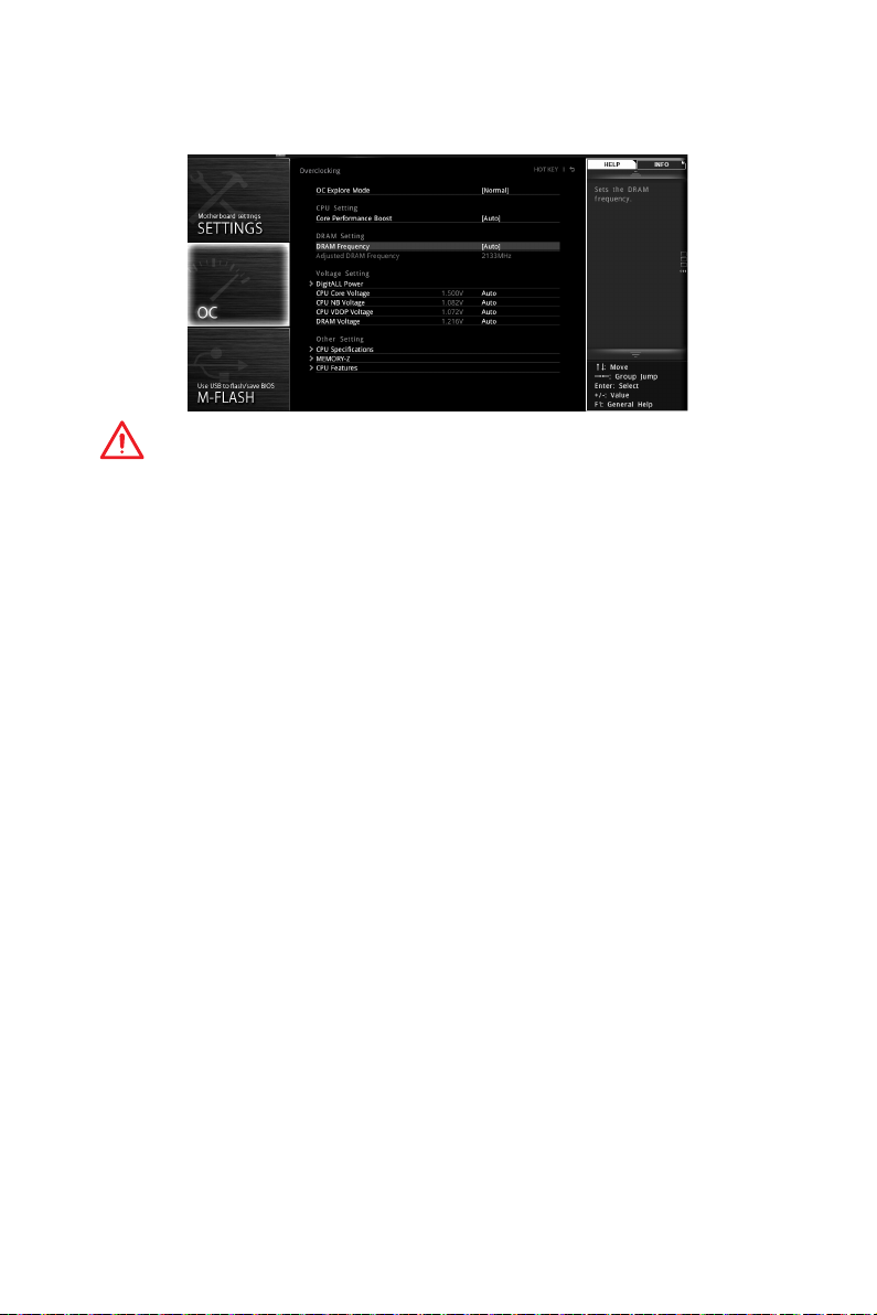
OC Menu (menu overclocking)
Ce menu est destiné aux utilisateurs avancés souhaitant overclocker leur carte mère.
Important
y
L’overclocking manuel du PC n’est recommandé que pour les utilisateurs avancés.
y
L’overclocking n’est pas garanti et une mauvaise manipulation peut rendre nulle
votre garantie et sévèrement endommager votre matériel.
y
Si vous n’êtes pas familier avec l’overclocking, nous vous recommandons d’utiliser
OC GENIE 4 pour un overclocking simplifié et plus stable.
f OC Explore Mode [Normal]
Active ou désactive le mode Normal ou Expert des réglages OC.
[Normal] Fournit les réglages OC standards dans les réglages BIOS.
[Expert] Fournit les réglages OC avancés pour les utilisateurs avancés et à
Remarque : Nous utilisons le symbole * pour indiquer les réglages OC du mode
Expert.
f CPU Frequency [Auto]
Définit la fréquence du processeur.
f Core Performance Boost [Auto]
Active ou désactive la technologie Core Performance Boost (CPB). Ce menu est
seulement disponible si le processeur installé supporte cette fonction.
f Downcore Control [Auto] (en option)
Définir le nombre de cœurs du processeur à utiliser. Ce menu est seulement
disponible si le processeur installé supporte cette fonction.
f DRAM Frequency [Auto]
Définit la fréquence de la mémoire. Veuillez noter que les résultats de l’overclocking
ne sont pas garantis.
f Adjusted DRAM Frequency
Affiche la fréquence ajustée de la mémoire. Fonctionne en lecture seule.
configurer dans les réglages BIOS.
Configuration du BIOS
27
Page 98

f Advanced DRAM Configuration
Appuyez sur la touche Entrée pour entrer dans le sous-menu. L’utilisateur
peut régler la synchronisation de mémoire de chaque barrette de mémoire. Le
système peut être instable ou peut ne plus redémarrer après le changement de la
synchronisation de la mémoire. Dans ce cas-là, veuillez effacer les données CMOS
et remettre les réglages par défaut (référez-vous à la section cavalier/ bouton Clear
CMOS (en option) pour effacer les données CMOS et entrez ensuite dans le BIOS pour
charger les réglages par défaut).
f DigitALL Power
Appuyez sur la touche Entrée pour entrer dans le sous-menu. Gère l’alimentation
numérique du contrôleur PWM du processeur.
fCPU Loadline Calibration Control [Auto]
La tension du processeur diminue proportionnellement à la charge du processeur.
Une valeur plus élevée peut entraîner une tension plus élevée et de bonnes
performances d’overclocking mais augmentera la température du processeur
et du module de régulation de tension (VRM). Mis en Auto, le BIOS configure ce
réglage automatiquement.
fCPU NB Loadline Calibration Control [Auto]
La tension du CPU-NB diminue proportionnellement à la charge du CPU-NB.
Une valeur plus élevée peut entraîner une tension plus élevée et de bonnes
performances d’overclocking mais augmentera la température. Mis en Auto, le
BIOS configure ce réglage automatiquement.
fCPU Over Voltage Protection [Auto]
Définit une limite de tension pour la protection contre la surtension du CPU. En
Auto, le BIOS configure automatiquement ce réglage. Une tension plus élevée
protège moins et peut endommager le système.
fCPU Under Voltage Protection [Auto]
Définit une limite de tension pour la protection contre la sous-tension du CPU.
En Auto, le BIOS configure automatiquement ce réglage. Une tension plus élevée
protège moins et peut endommager le système.
fCPU Over Current Protection [Auto]
Définit une limite actuelle pour la protection contre la surtension du CPU. En Auto,
le BIOS configure automatiquement ce réglage.
[Auto] Le BIOS configure automatiquement ce réglage.
[Enhanced] Augmente la limite de consommation pour protéger contre la
fVR 12VIN OCP Expander [Auto]
Etendre la limitation de VR Over Current Protection avec la tension d’entrée
de 12V. La valeur d’extension plus haute signifie moins de protection. Par
conséquent, veuillez ajuster le courant soigneusement en cas nécessaire, ou
ceci endommagerait le CPU/ VR MOS. Mis en Auto, le BIOS configure ce réglages
automatiquement.
surcharge électrique.
Configuration du BIOS
28
Page 99

f CPU Voltages control [Auto]
Permet de définir les tensions relatives au processeur. En mode Auto, le BIOS
configure ces tensions automatiquement. Vous pouvez également les paramétrer
manuellement.
f DRAM Voltages control [Auto]
Permet de définir les tensions relatives à la mémoire. En mode Auto, le BIOS
configure ces tensions automatiquement. Vous pouvez également les paramétrer
manuellement.
f CPU Memory Changed Detect [Enabled]*
Activer ou désactiver l’envoi de message d’alerte au démarrage lorsque le CPU ou la
mémoire a été remplacé.
[Enabled] Le système enverra un message d’alerte au démarrage et vous devrez
[Disabled] Désactive cette fonction et conserve les paramètres actuels du BIOS.
f CPU Specifications
Appuyez sur la touche Entrée pour accéder au sous-menu. Ce sous-menu affiche
les caractéristiques du processeur installé. Vous pouvez également accéder à ce
sous-menu à tout moment en appuyant sur la touche [F4]. Fonctionne uniquement en
lecture seule.
fCPU Technology Support
Appuyez sur la touche Entrée pour accéder au sous-menu. Ce sous-menu affiche
les principales fonctions et technologies prises en charge par le processeur
installé. Fonctionne uniquement en lecture seule.
f MEMORY-Z
Appuyez sur la touche Entrée pour accéder au sous-menu. Ce sous-menu affiche tous
les réglages et timings de la mémoire installée. Vous pouvez également accéder à ce
sous-menu à tout moment en appuyant sur la touche [F5].
fDIMMx Memory SPD
Appuyez sur la touche Entrée pour accéder au sous-menu. Ce sous-menu affiche
les caractéristiques de la mémoire installée. Fonctionne uniquement en lecture
seule.
f CPU Features
Appuyez sur la touche Entrée pour accéder au sous-menu.
fAMD Cool’n’Quiet [Enabled]
La technologie Cool’n’Quiet peut efficacement et dynamiquement réduire la
vitesse et la consommation d’énergie du processeur.
fSVM Mode [Disabled]
Active ou désactive le mode AMD SVM (Secure Virtual Machine).
fCore C6 state [Auto]
Active ou désactive la fonction C6 state.
charger les paramètres par défaut pour les nouveaux périphériques.
Configuration du BIOS
29
Page 100

Informations sur les logiciels
Veuillez vous référer au site www.msi.com pour télécharger et mettre à jour les
derniers utilitaires et pilotes.
Installer Windows® 7 64-bit/ Windows®10 64-bit
1. Allumez l’ordinateur.
2. Insérez le disque de Windows
Remarque : Du fait des limites du chipset pendant l’installation de Windows® 7,
les lecteurs optiques USB et les clés USB ne seront pas supportés. Vous pouvez
utiliser MSI Smart Tool pour installer Windows® 7.
3. Appuyez sur le bouton Restart du boîtier de l’ordinateur.
4. Appuyez sur la touche F11 pendant le POST (Power-On Self Test) du système pour
entrer dans le menu Boot Menu.
5. Choisissez le lecteur optique du Boot Menu.
6. Appuyez sur n’importe quelle touche lorsqu’apparaît le message (Press any key
to boot from CD or DVD).
7. Suivez les instructions à l’écran pour installer Windows
Installer les pilotes
1. Allumez l’ordinateur sous Windows® 7/ 10.
2. Insérez le disque MSI
3. L’outil d’installation apparaît automatiquement. Il trouvera et listera tous les
pilotes dont vous avez besoin.
4. Cliquez sur le bouton Install.
5. L’installation des pilotes commence. Une fois terminée, il vous sera demandé de
redémarrer.
6. Cliquez sur le bouton OK pour terminer.
7. Redémarrez votre ordinateur.
®
7/ 10 dans le lecteur optique.
®
Driver Disc dans le lecteur optique.
®
7/10.
Installer les utilitaires
Avant d’installer les utilitaires, il faut compléter l’installation des pilotes.
1. Insérez le disque MSI
2. L’outil d’installation apparaît automatiquement.
3. Cliquez sur l’onglet Utilities.
4. Choisissez les utilitaires que vous voulez installer.
5. Cliquez sur le bouton Install.
6. L’installation des utilitaires commence. Une fois terminée, il vous sera demandé
de redémarrer.
7. Cliquez sur le bouton OK pour terminer.
8. Redémarrez votre ordinateur.
Informations sur les logiciels
30
®
Driver Disc dans le lecteur optique.
 Loading...