

Page 1
1
Unpacking
Un
packing
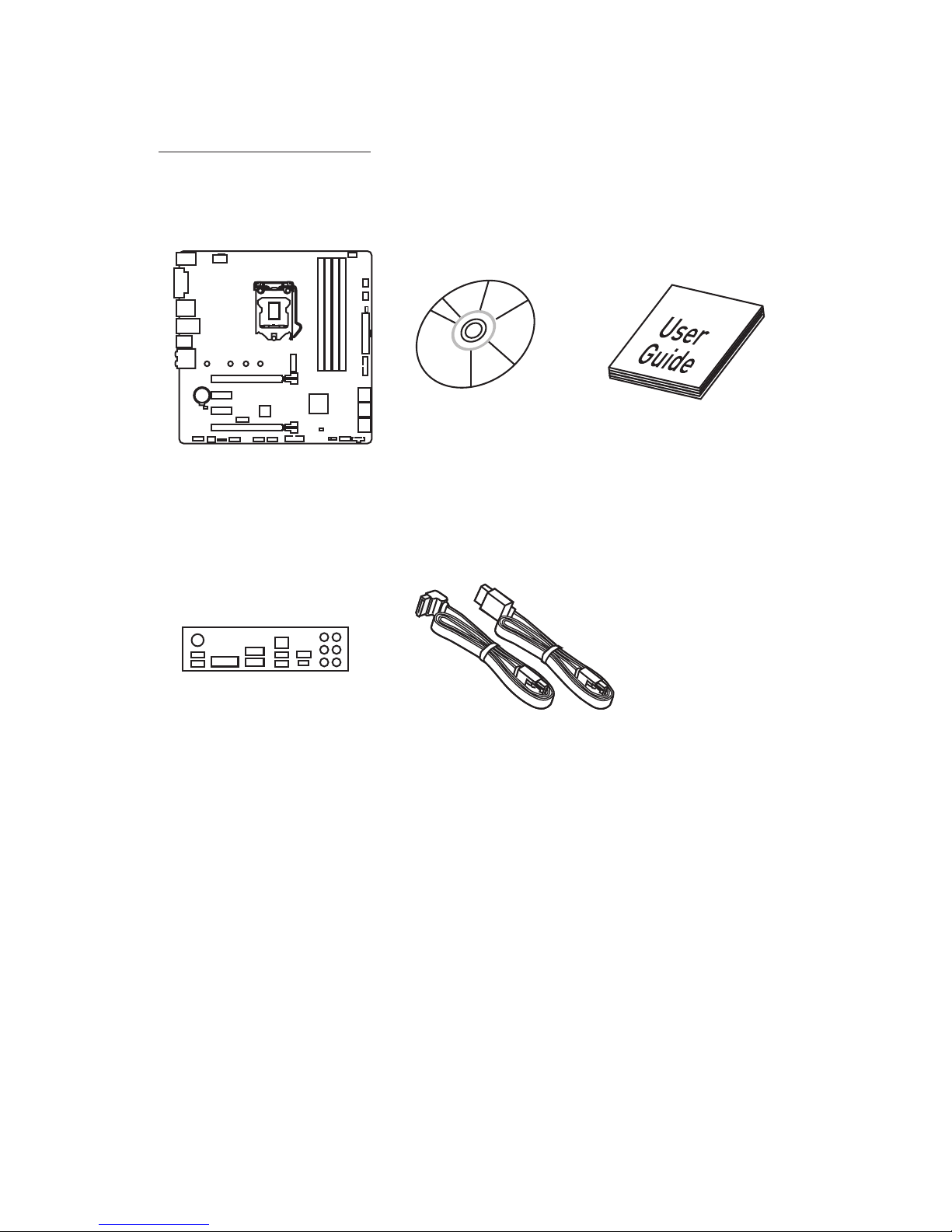
Thank you for buying the MSI® Z270M MORTAR/ B250M MORTAR motherboard. Check
to make sure your motherboard box contains the following items. If something is
missing, contact your dealer as soon as possible.
SATA Cable x2
Drivers & Utilities
Disc
Motherboard User
Guide
I/O Shield
Motherboard
Page 2

2
Safety Information
Safety Information
y The components included in this package are prone to damage from electrostatic
discharge (ESD). Please adhere to the following instructions to ensure successful
computer assembly.
y Ensure that all components are securely connected. Loose connections may cause
the computer to not recognize a component or fail to start.
y Hold the motherboard by the edges to avoid touching sensitive components.
y It is recommended to wear an electrostatic discharge (ESD) wrist strap when
handling the motherboard to prevent electrostatic damage. If an ESD wrist strap
is not available, discharge yourself of static electricity by touching another metal
object before handling the motherboard.
y Store the motherboard in an electrostatic shielding container or on an anti-static
pad whenever the motherboard is not installed.
y Before turning on the computer, ensure that there are no loose screws or metal
components on the motherboard or anywhere within the computer case.
y Do not boot the computer before installation is completed. This could cause
permanent damage to the components as well as injury to the user.
y If you need help during any installation step, please consult a certified computer
technician.
y Always turn off the power supply and unplug the power cord from the power outlet
before installing or removing any computer component.
y Keep this user guide for future reference.
y Keep this motherboard away from humidity.
y Make sure that your electrical outlet provides the same voltage as is indicated on
the PSU, before connecting the PSU to the electrical outlet.
y Place the power cord such a way that people can not step on it. Do not place
anything over the power cord.
y All cautions and warnings on the motherboard should be noted.
y If any of the following situations arises, get the motherboard checked by service
personnel:
Liquid has penetrated into the computer.
The motherboard has been exposed to moisture.
The motherboard does not work well or you can not get it work according to user
guide.
The motherboard has been dropped and damaged.
The motherboard has obvious sign of breakage.
y Do not leave this motherboard in an environment above 60°C (140°F), it may damage
the motherboard.
Page 3

3
Quick Start
Intel® LGA 1151 CPU
DDR4 Memory
Graphics Card
SATA Hard Disk Drive
SATA DVD Drive
A Package of Screws
Phillips Screwdriver
Chassis
Power Supply Unit
CPU Fan Thermal Paste
Quick Start
Preparing Tools and Components
Page 4
4
Quick Start
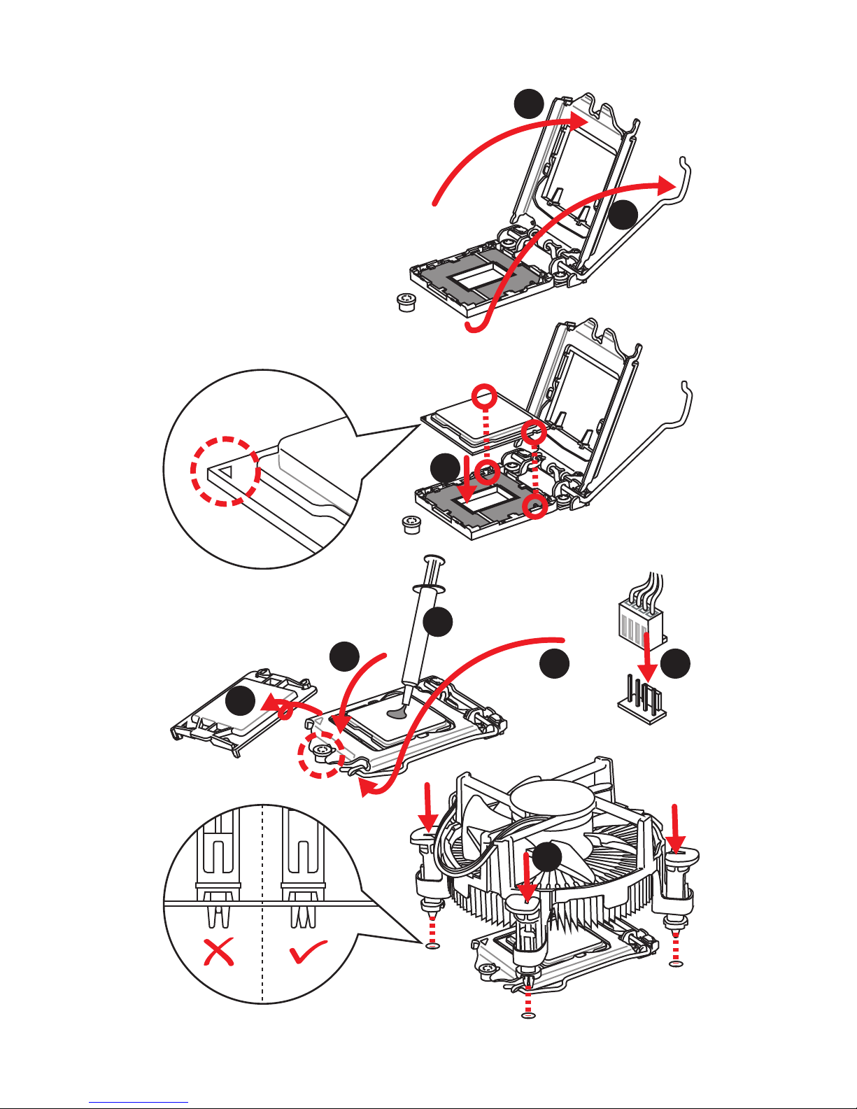
Installing a Processor
1
2
3
6
4
5
7
8
9
Page 5
5
Quick Start
1
1
2
2
3
3
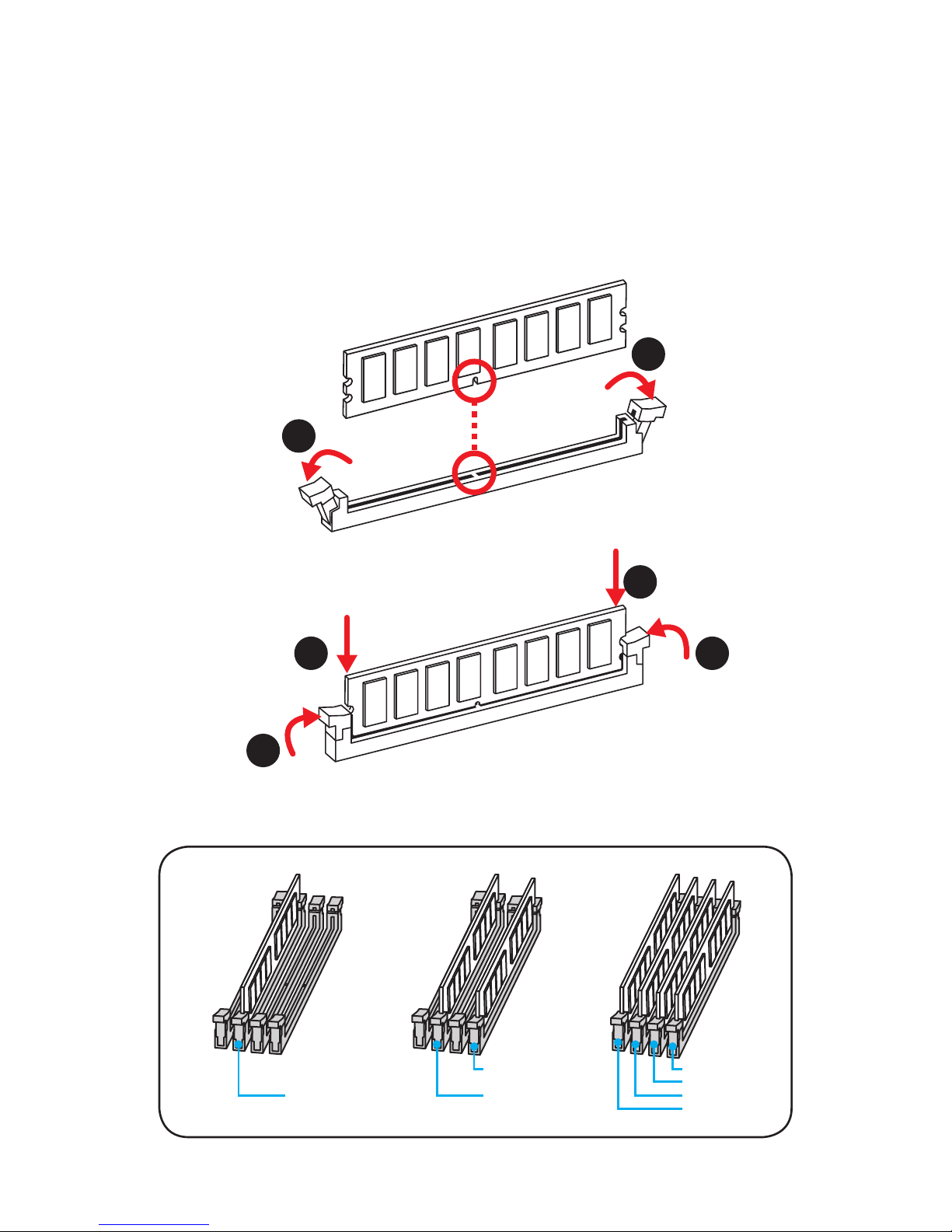
Installing DDR4 memory
DIMMB2 DIMMB2
DIMMB1
DIMMA2 DIMMA2 DIMMA2
DIMMA1
Page 6
6
Quick Start
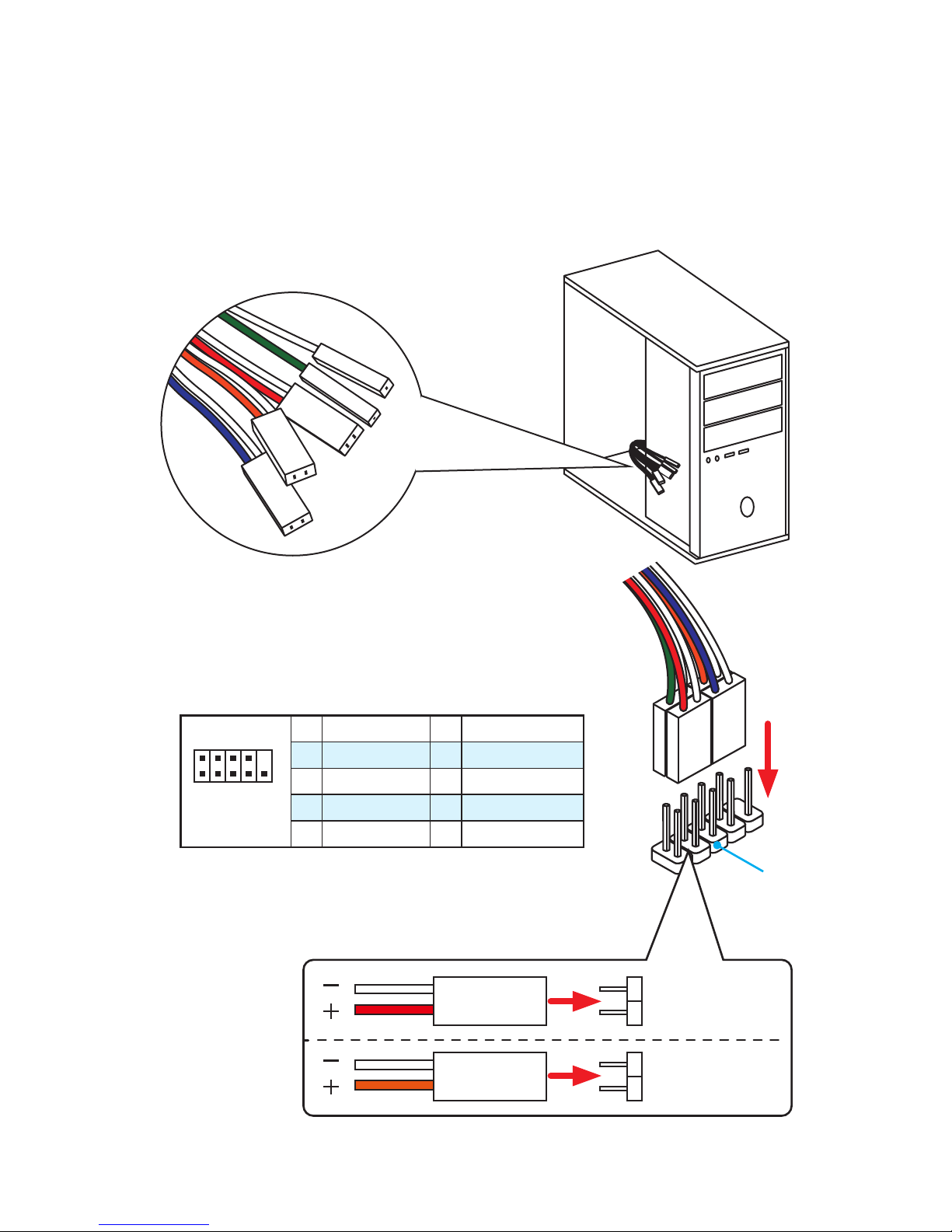
Connecting the Front Panel Header
1
2 10
9
JFP1
1 HDD LED + 2 Power LED +
3 HDD LED - 4 Power LED -
5 Reset Switch 6 Power Switch
7 Reset Switch 8 Power Switch
9 Reserved 10 No Pin
RESET SW
POWER SW
POWER LED+
POWER LED-
HDD LED
HDD LED
RESET SW
JFP1
HDD LED
HDD LED HDD LED +
POWER LED POWER LED +
POWER LED
Page 7
7
Quick Start
BAT1
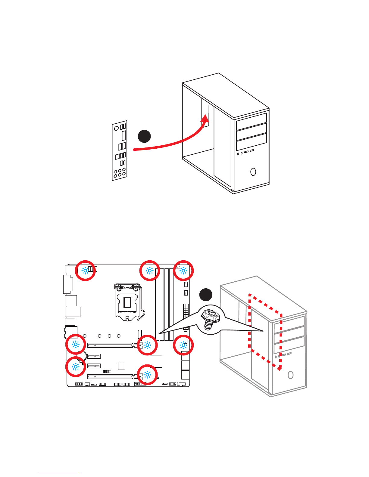
Installing the Motherboard
1
2
Page 8
8
Quick Start
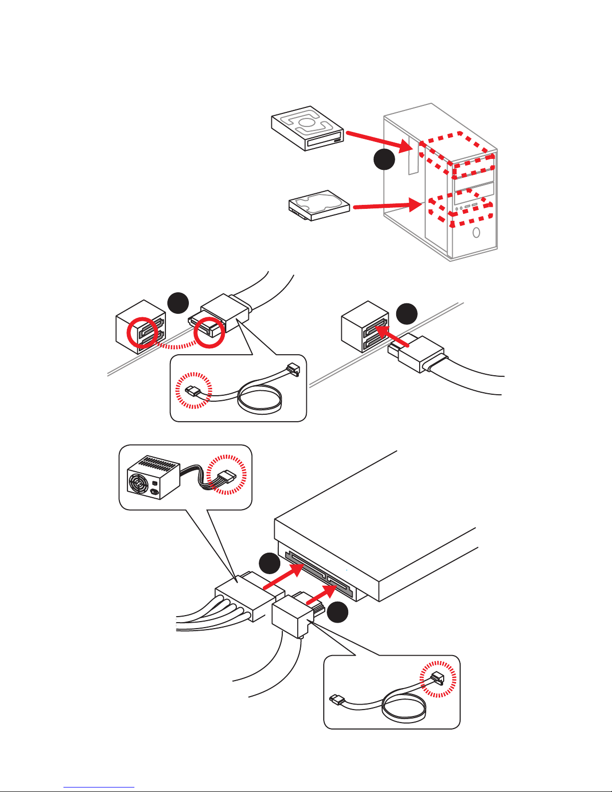
Installing SATA Drives
1
2
3
4
5
Page 9
9
Quick Start
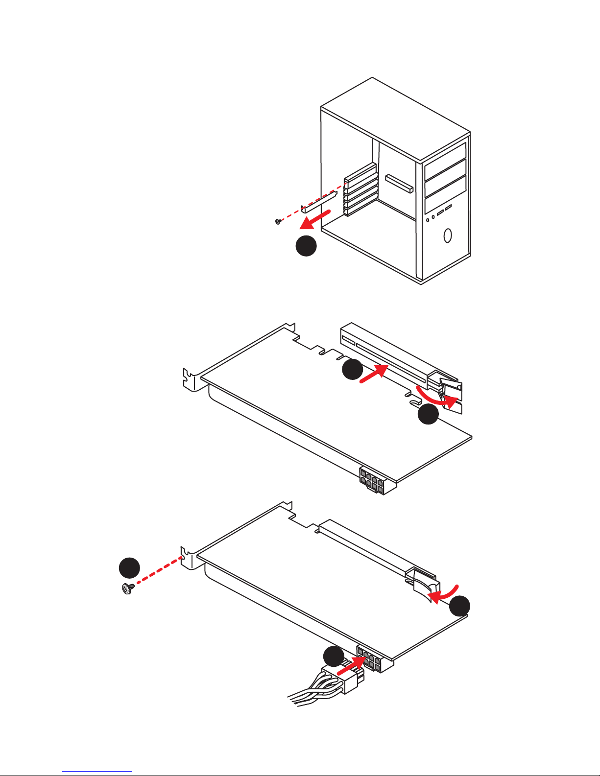
1
Installing a Graphics Card
2
3
4
5
6
Page 10
10
Quick Start
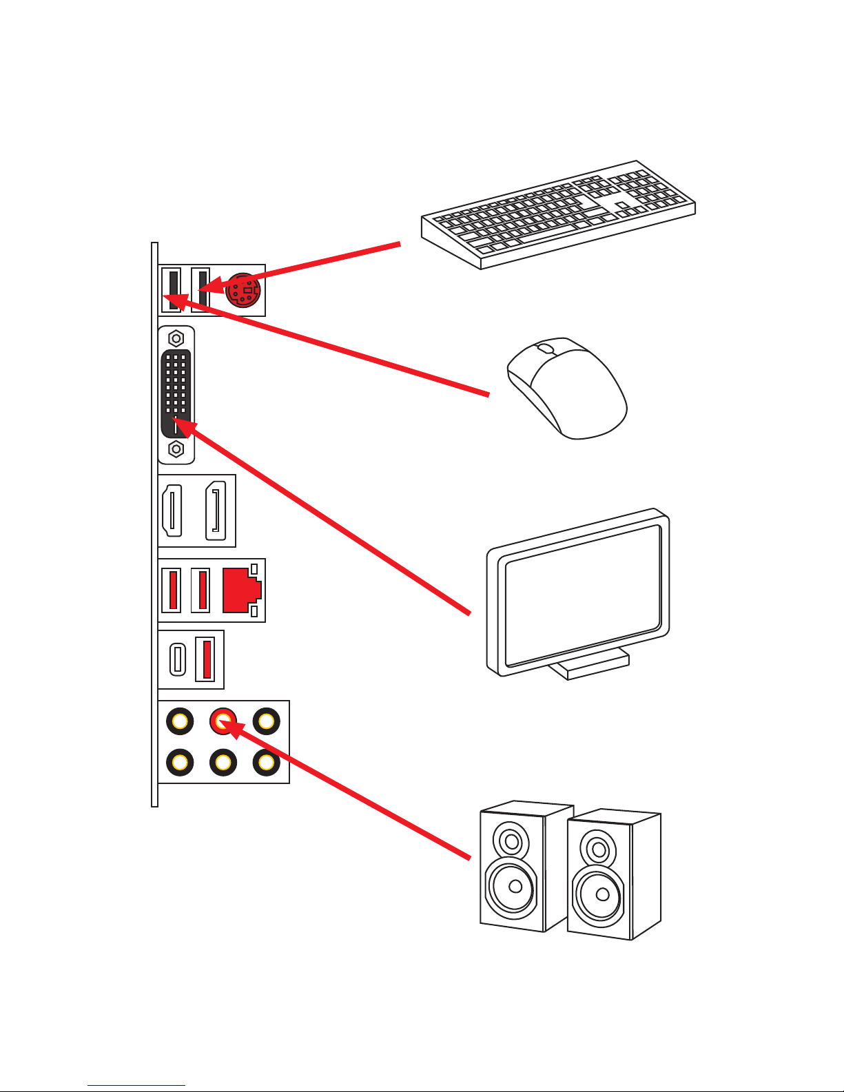
Connecting Peripheral Devices
Page 11
11
Quick Start
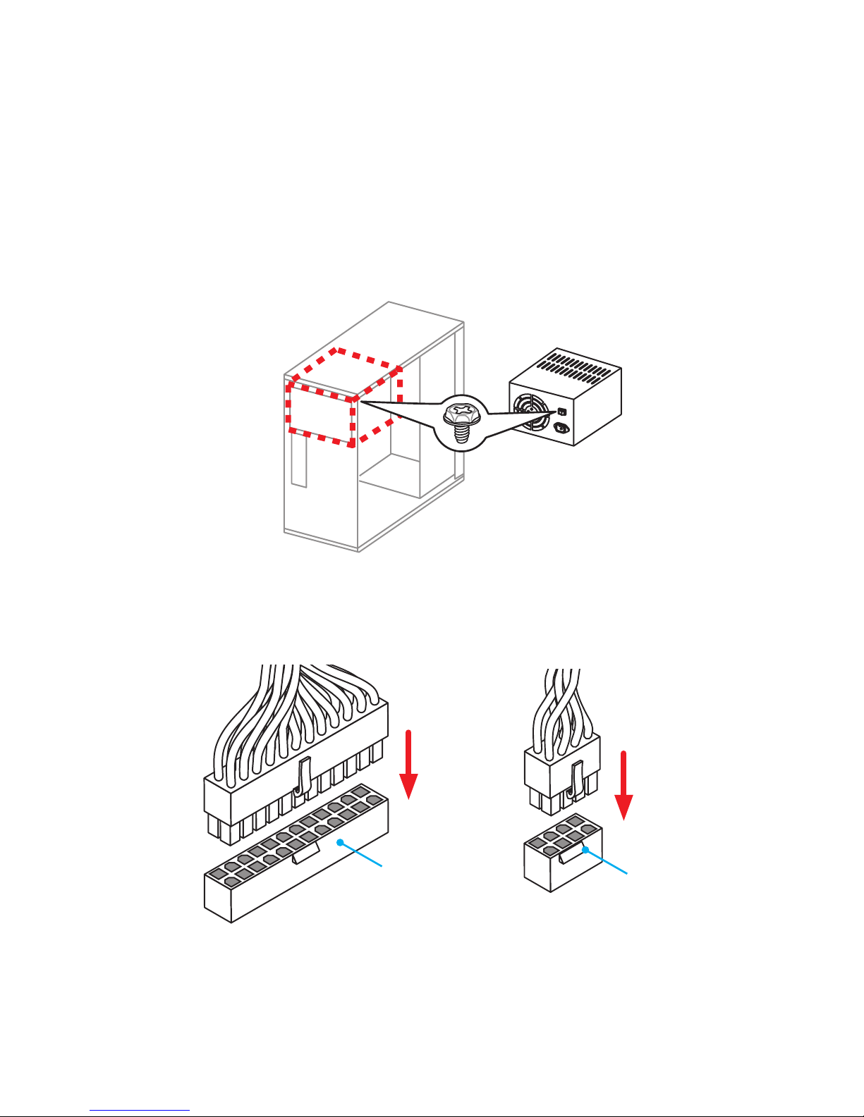
Connecting the Power Connectors
ATX_PWR1
CPU_PWR1
Page 12
12
Quick Start
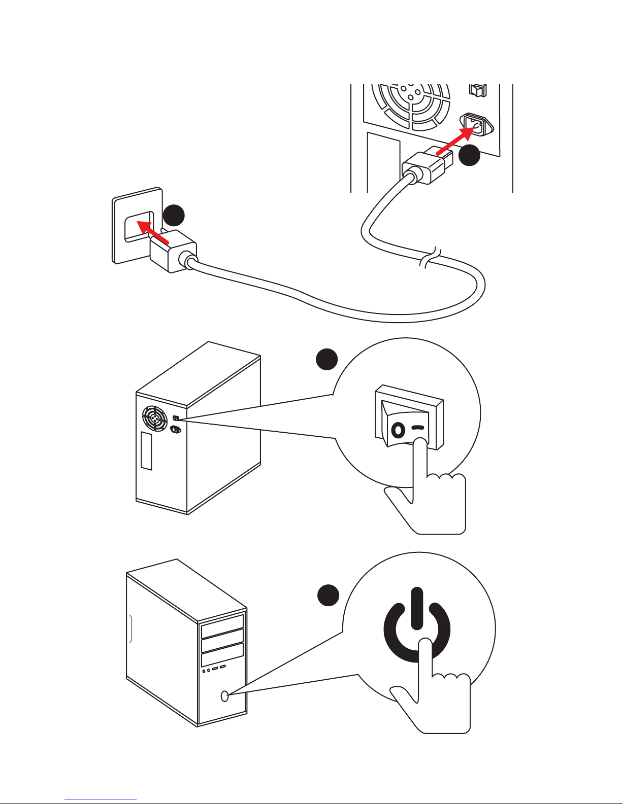
Power On
1
4
2
3
Page 13

13
Contents
Contents
Unpacking .............................................................................................................. 1
Safety Information ................................................................................................. 2
Quick Start ............................................................................................................. 3
Preparing Tools and Components .......................................................................... 3
Installing a Processor ............................................................................................. 4
Installing DDR4 memory ........................................................................................ 5
Connecting the Front Panel Header ....................................................................... 6
Installing the Motherboard ..................................................................................... 7
Installing SATA Drives............................................................................................. 8
Installing a Graphics Card ...................................................................................... 9
Connecting Peripheral Devices ............................................................................ 10
Connecting the Power Connectors ....................................................................... 11
Power On............................................................................................................... 12
Specifications ....................................................................................................... 15
Block Diagram .................................................................................................... 20
Rear I/O Panel ..................................................................................................... 21
LAN Port LED Status Table................................................................................... 21
Audio Ports Configuration .................................................................................... 21
Realtek HD Audio Manager .................................................................................. 22
Overview of Components .................................................................................... 24
CPU Socket ........................................................................................................... 26
DIMM Slots ............................................................................................................ 27
PCI_E1~4: PCIe Expansion Slots .......................................................................... 28
M2_1: M.2 Slot (Key M) ......................................................................................... 29
SATA1~6: SATA 6Gb/s Connectors ....................................................................... 30
JFP1, JFP2: Front Panel Connectors ................................................................... 31
JCOM1: Serial Port Connector ............................................................................. 31
JAUD1: Front Audio Connector ............................................................................ 31
CPU_PWR1, ATX_PWR1: Power Connectors ....................................................... 32
JTPM1: TPM Module Connector ........................................................................... 32
JUSB1~2: USB 2.0 Connectors ............................................................................. 33
JUSB3~4: USB 3.1 Gen1 Connectors (optional) ................................................... 33
CPU_FAN1,SYS_FAN1~3: Fan Connectors ........................................................... 34
JCI1: Chassis Intrusion Connector ....................................................................... 35
JBAT1: Clear CMOS (Reset BIOS) Jumper ........................................................... 35
Page 14

14
Contents
JLED1: RGB LED connector ................................................................................. 36
EZ Debug LEDs ..................................................................................................... 36
BIOS Setup ........................................................................................................... 37
Entering BIOS Setup ............................................................................................. 37
Resetting BIOS ...................................................................................................... 38
Updating BIOS ....................................................................................................... 38
EZ Mode ................................................................................................................ 39
Advanced Mode .................................................................................................... 41
SETTINGS .............................................................................................................. 42
Advanced ............................................................................................................... 42
Boot ....................................................................................................................... 48
Security ................................................................................................................. 49
Save & Exit ............................................................................................................ 50
OC .......................................................................................................................... 51
M-FLASH .............................................................................................................. 58
OC PROFILE .......................................................................................................... 59
HARDWARE MONITOR .......................................................................................... 60
Software Description ........................................................................................... 61
Installing Windows® 7/ 8.1/ 10.............................................................................. 61
Installing Drivers .................................................................................................. 61
Installing Utilities ................................................................................................. 61
COMMAND CENTER ............................................................................................. 62
LIVE UPDATE 6 ...................................................................................................... 66
GAMING APP ......................................................................................................... 69
X-BOOST ............................................................................................................... 74
RAMDISK............................................................................................................... 76
GAMING LAN MANAGER ...................................................................................... 77
XSplit Gamecaster V2 ........................................................................................... 79
SteelSeries Engine 3 ............................................................................................ 83
CPU-Z.................................................................................................................... 85
Intel
®
Extreme Tuning Utility ................................................................................ 86
RAID Configuration .............................................................................................. 87
Using Intel® Rapid Storage Technology Option ROM ........................................... 87
Degraded RAID Array ........................................................................................... 90
Troubleshooting .................................................................................................. 92
Regulatory Notices .............................................................................................. 93
Page 15

15
Specifications
Specifications
CPU
y Supports 7th/6th Gen Intel
®
Core™ i3/i5/i7 processors,
and Intel® Pentium® and Celeron® processors for Socket
LGA1151
Chipset Intel
®
Z270/ B250 Chipset
Memory
y 4x DDR4 memory slots, support up to 64GB
Z270 chipset + 7th Gen processors support DDR4
3800(OC)/ 3600(OC)/ 3200(OC)/ 3000(OC)/ 2800(OC)/
2600(OC)/ 2400/ 2133 MHz*
Z270 chipset + 6th Gen processors support DDR4
3600(OC)/ 3200(OC)/ 3000(OC)/ 2800(OC)/ 2600(OC)/
2400(OC)/ 2133 MHz*
B250 chipset + 7th Gen processors support DDR4 2400/
2133 MHz*/ **
B250 chipset + 6th Gen processors support DDR4 2133
MHz*/ **
y Dual channel memory architecture
y Supports Intel
®
Extreme Memory Profile (XMP)**
** DDR4 memory modules can only run at maximum of 2400 MHz for 7th Gen
processors and 2133 MHz for 6 th Gen processors on XMP mode.
Expansion Slots
y 2x PCIe 3.0 x16 slots (support x16/x4 mode)
y 2x PCIe 3.0 x1 slots
Onboard Graphics
y 1x DVI-D port, supporting a maximum resolution of
1920x1200@60Hz
y 1x DisplayPort, supports a maximum resolution
of 4096x2304@24Hz, 2560x1600@60Hz,
3840x2160@60Hz,1920x1200@60Hz
y 1x HDMI
™
port, supports a maximum resolution of
4096x2160@30Hz(7th CPU), 4096x2160@24Hz(6th CPU),
2560x1600@60Hz
Multi-GPU y Supports 2-Way AMD
®
CrossFire™ Technology
Continued on next page
Page 16

16
Specifications
Continued from previous page
Storage
Intel
®
Z270/ B250 Chipset
y 6x SATA 6Gb/s ports*
y 1x M.2 slot (Key M)
Support up to PCIe 3.0 x4 and SATA 6Gb/s
Supports 2242/ 2260 /2280/ 22110 storage devices
Support PCIe 3.0 x4 NVMe U.2 SSD with Turbo U.2 Host
Card**
Intel
®
Optane™ Memory Ready
y Supports Intel
®
Smart Response Technology for Intel
Core™ processors
* The SATA1 port will be unavailable when an M.2 SATA SSD module has been
installed in the M.2 slot.
** The Turbo U.2 Host Card is not included, please purchase separately.
RAID
Intel
®
Z270 Chipset
y Supports RAID 0, RAID 1, RAID 5 and RAID 10 for SATA
storage devices
USB
y Intel
®
Z270 Chipset
8x USB 3.1 Gen1 (SuperSpeed USB) ports (3 Type-A
ports + 1 Type-C port on the back panel, 4 ports available
through the internal USB connectors)
6x USB 2.0 (High-speed USB) ports (2 Type-A ports on
the back panel, 4 ports available through the internal
USB connectors)
y Intel
®
B250 Chipset
6x USB 3.1 Gen1 (SuperSpeed USB) ports (3 Type-A
ports + 1 Type-C port on the back panel, 2 ports available
through the internal USB connector)
6x USB 2.0 (High-speed USB) ports (2 Type-A ports on
the back panel, 4 ports available through the internal
USB connectors)
Audio
y Realtek
®
ALC892 Codec
y 7.1-Channel High Definition Audio
LAN 1x Intel
®
I219-V Gigabit LAN controller
Continued on next page
Page 17

17
Specifications
Continued from previous page
Back Panel
Connectors
y 1x PS/2 mouse & keyboard combo port
y 2x USB 2.0 ports
y 1x DVI-D port
y 1x DisplayPort
y 1x HDMI
™
port
y 1x LAN (RJ45) port
y 3x USB 3.1 Gen1 Type-A ports
y 1x USB 3.1 Gen1 Type-C port
y 6x OFC audio jacks
Internal Connectors
y 1x 24-pin ATX main power connector
y 1x 8-pin ATX 12V power connector
y 6x SATA 6Gb/s connectors
y 1x M.2 slot
y 2x USB 3.1 Gen1 connectors (supports additional 4 USB
3.1 Gen1 ports) (For Z270 chipset)
y 1x USB 3.1 Gen1 connector (supports additional 2 USB 3.1
Gen1 ports) (For B250 chipset)
y 2x USB 2.0 connectors (supports additional 4 USB 2.0
ports)
y 1x 4-pin CPU fan connector
y 3x 4-pin system fan connectors
y 1x Front panel audio connector
y 2x Front panel connectors
y 1x Serial port connector
y 1x RGB LED connector
y 1x TPM module connector
y 1x TBT connector
y 1x Chassis Intrusion connector
y 1x Clear CMOS jumper
I/O Controller NUVOTON NCT6795 Controller Chip
Hardware Monitor
y CPU/System temperature detection
y CPU/System fan speed detection
y CPU/System fan speed control
From Factor
y Micro-ATX Form Factor
y 9.6 in. x 9.6 in. (24.4 cm x 24.4 cm)
Continued on next page
Page 18

18
Specifications
Continued from previous page
BIOS Features
y 1x 128 Mb flash
y UEFI AMI BIOS
y ACPI 5.0, PnP 1.0a, SM BIOS 2.8
y Multi-language
Software
y Drivers
y SUPER CHARGER
y FAST BOOT
y COMMAND CENTER
y LIVE UPDATE 6
y MSI SMART TOOL
y DRAGON EYE
y GAMING APP
y X-BOOST
y RAMDISK
y GAMING LAN Manager
y XSplit Gamecaster V2
y SteelSeries Engine 3
y CPU-Z MSI GAMING
y Intel
®
Extreme Tuning Utility
y Norton
™
Internet Security Solution
y Google Chrome
™
, Google Toolbar, Google Drive
Continued on next page
Page 19

19
Specifications
Continued from previous page
MSI Special
Features
y Audio Boost
y GAMING LAN with cFos
y WTFast
y Intel Optane
TM
Memory Ready
y Turbo M.2
y Smart Fan Control
y Mystic light SYNC
y Mystic Light Extension (RGB)
y Gaming DNA with bottom LED
y PCI-E Steel Armor
y M.2 Steel Armor
y Muitl GPU - CrossFire Technology
y DDR4 Boost
y GAME Boost
y X-Boost
y Military Class 5
y 7000+ Quality Test
y VR Ready
y Dragon eye
y Xsplit
y RAMDisk
y GAMING HOTKEY
y Click BIOS 5
Page 20
20
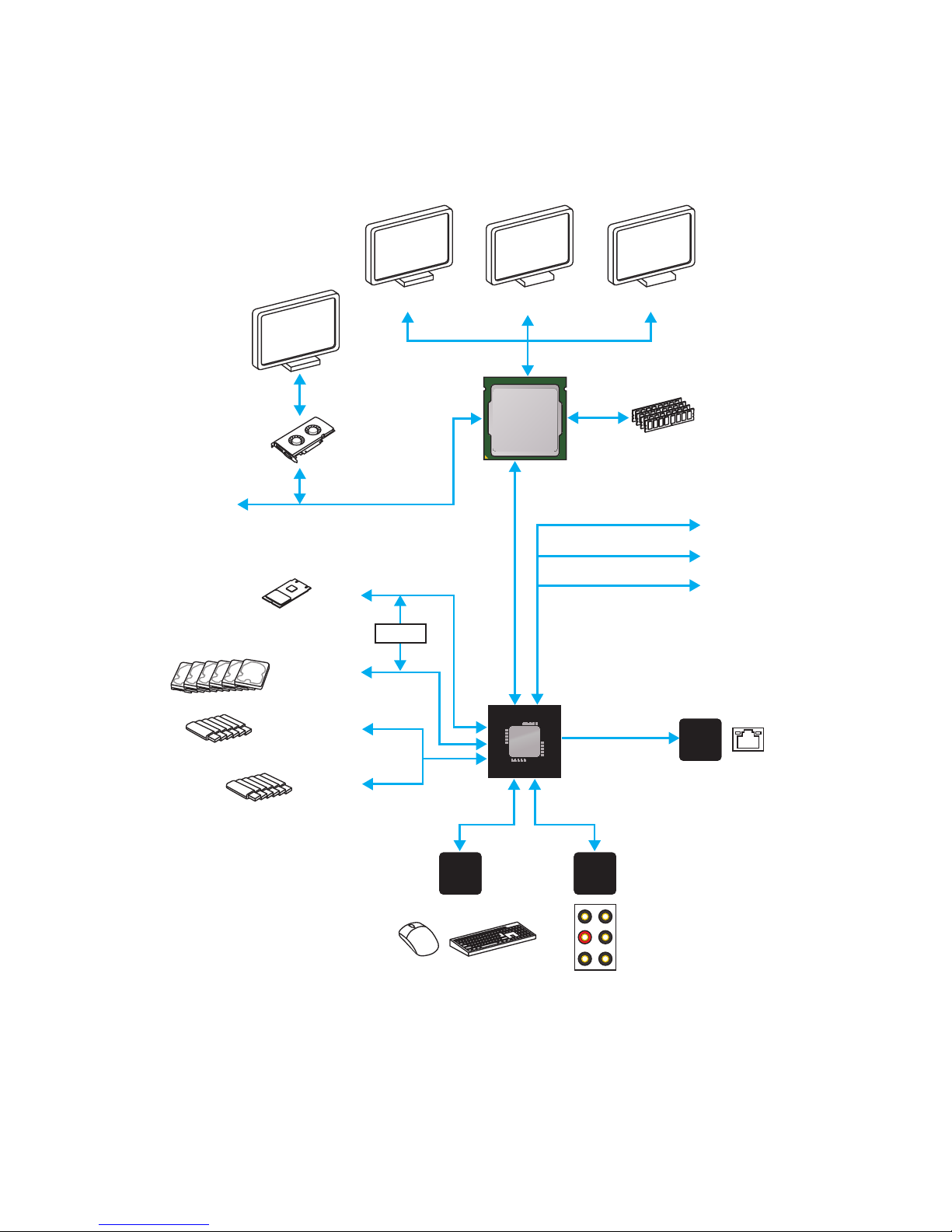
Block Diagram
Block Diagram
LPC Bus
2 Channel DDR4 Memory
8x/6x USB 3.1 Gen1
1 x M.2
6 x USB 2.0
PCI-E Bus
PCI Express Bus
P/S2 Mouse / Keyboard
Audio Jacks
DMI 3.0
CHIPSET
CPU
NV6795
Super I/O
Realtek
ALC892
Intel
I219-V
x4
x1
PCI Express Bus
DVI-D HDMI
DisplayPort
Switch
x1
PCIe x1 slot
PCIe x1 slot
PCIe x16 slot
6 x SATA 6Gb/s
Page 21
21
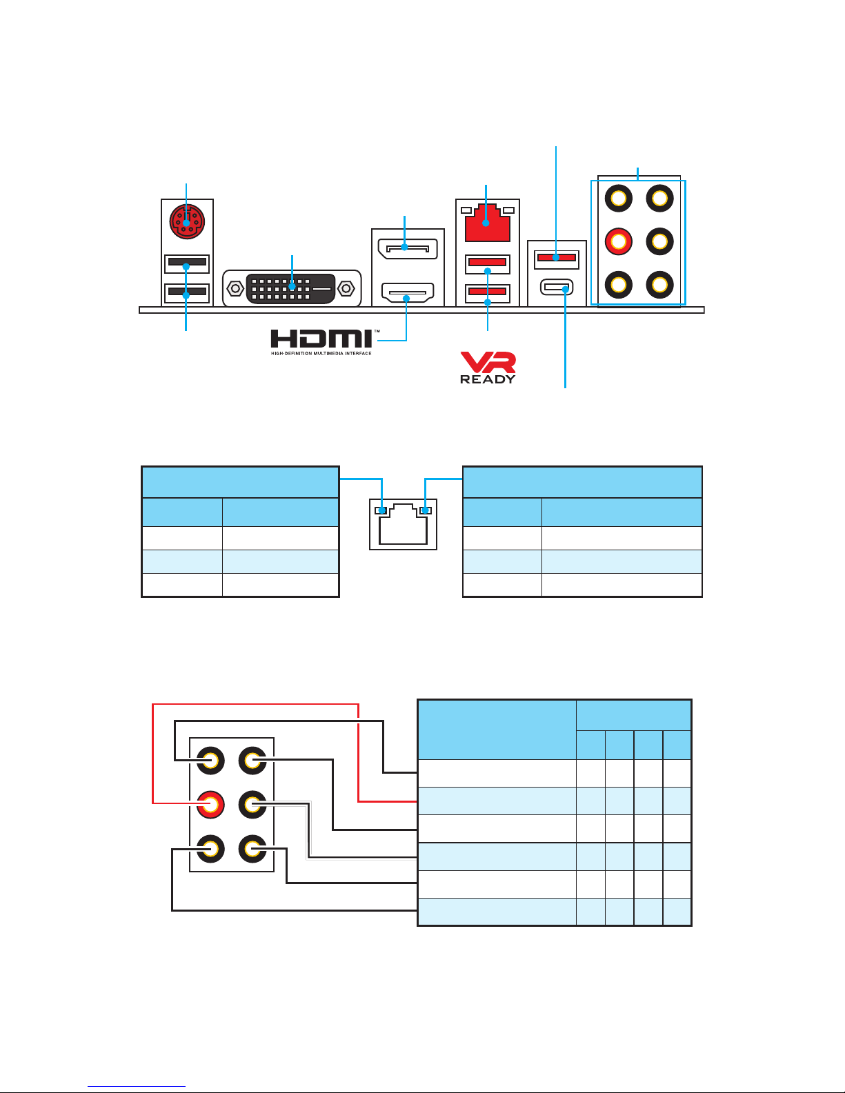
Rear I/O Panel
Rear I/O Panel
PS/2 Port
LAN
USB 2.0
Audio Ports
DVI-D
DisplayPort
USB 3.1 Gen1 Type-A
USB 3.1 Gen1 Type-C
USB 3.1 Gen1 Type-A
Link/ Activity LED
Status Description
Off No link
Yellow Linked
Blinking Data activity
Speed LED
Status Description
Off 10 Mbps connection
Green 100 Mbps connection
Orange 1 Gbps connection
LAN Port LED Status Table
Audio Ports Configuration
Audio Ports
Channel
2 4 6 8
Line-In
Line-Out/ Front Speaker Out ● ● ● ●
Rear Speaker Out ● ● ●
Center/ Subwoofer Out ● ●
Side Speaker Out ●
Mic In
(●: connected, Blank: empty)
Page 22
22
Rear I/O Panel
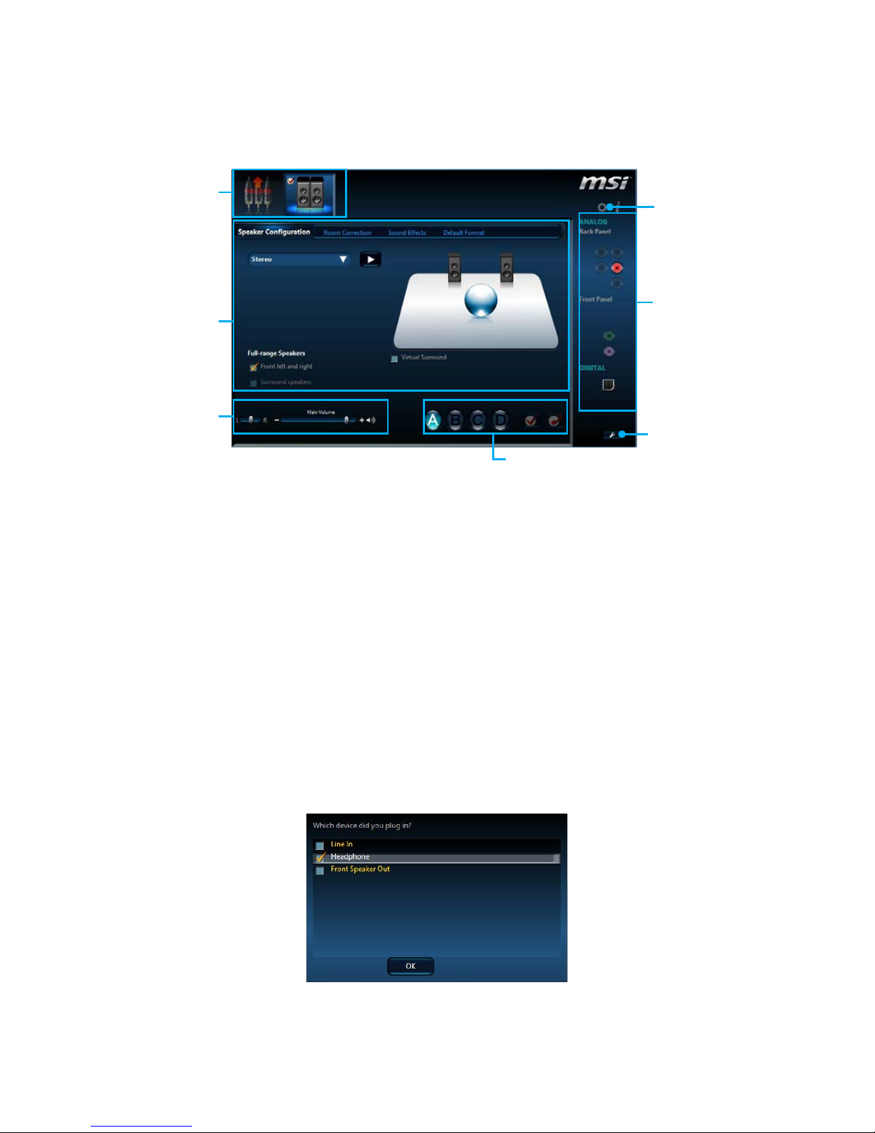
Realtek HD Audio Manager
After installing the Realtek HD Audio driver, the Realtek HD Audio Manager icon will
appear in the system tray. Double click on the icon to launch.
Jack Status
Device
Selection
Connector
Strings
Profiles
Main Volume
Application
Enhancement
Advanced
Settings
y Device Selection - allows you to select a audio output source to change the related
options. The check sign indicates the devices as default.
y Application Enhancement - the array of options will provide you a complete
guidance of anticipated sound effect for both output and input device.
y Main Volume - controls the volume or balance the right/left side of the speakers
that you plugged in front or rear panel by adjust the bar.
y Profiles - toggles between profiles.
y Advanced Settings - provides the mechanism to deal with 2 independent audio
streams.
y Jack Status - depicts all render and capture devices currently connected with your
computer.
y Connector Settings - configures the connection settings.
Auto popup dialog
When you plug into a device at an audio jack, a dialogue window will pop up asking you
which device is current connected.
Each jack corresponds to its default setting as shown on the next page.
Page 23
23
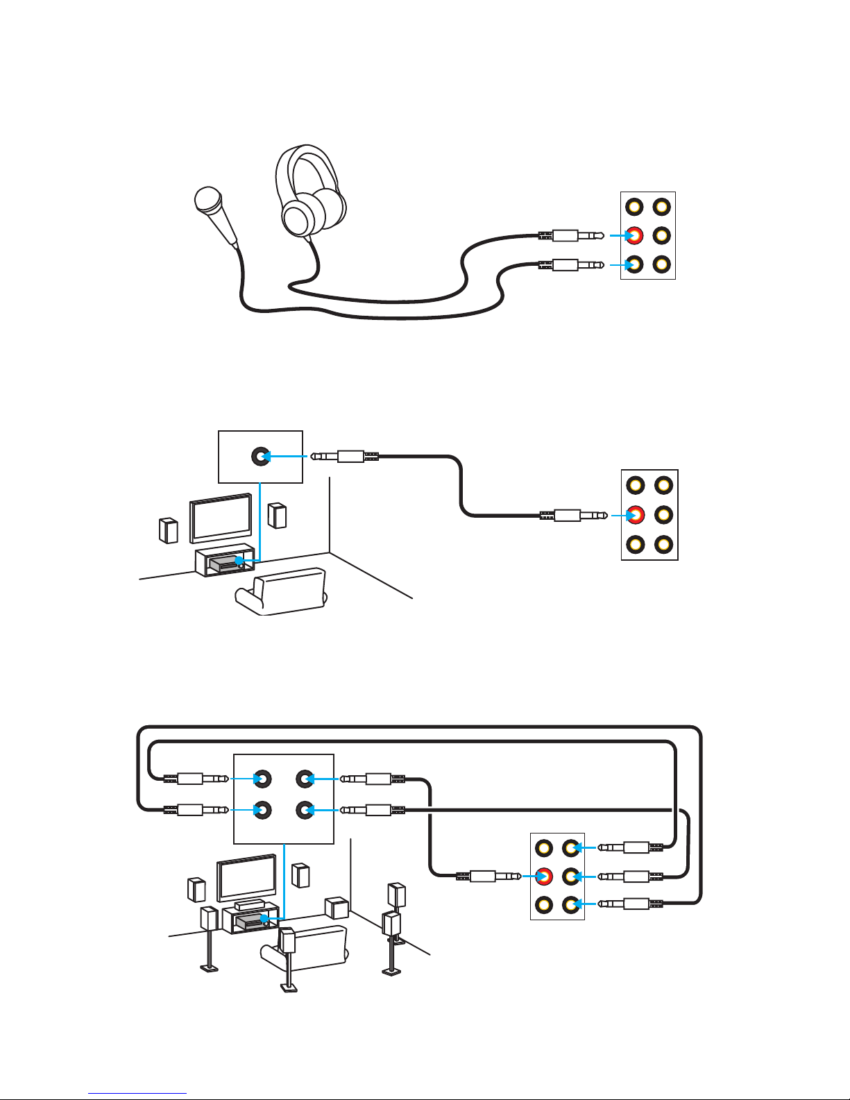
Rear I/O Panel
Audio jacks to headphone and microphone diagram
Audio jacks to stereo speakers diagram
Audio jacks to 7.1-channel speakers diagram
AUDIO INPUT
Rear Front
Side Center/
Subwoofer
AUDIO INPUT
Page 24
24
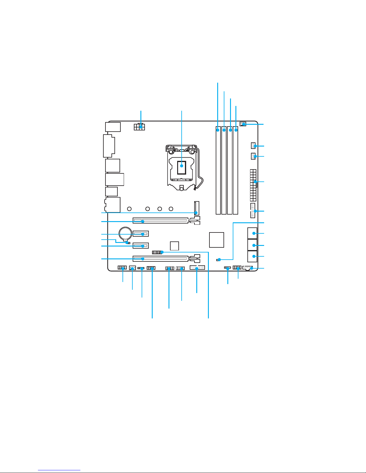
Overview of Components
BAT1
Overview of Components
PCI_E1
PCI_E2
SYSFAN1
JLED1
PCI_E3
PCI_E4
JBAT1
CPU SocketCPU_PWR1
ATX_PWR1
JUSB3
JUSB2
JCI1
JUSB4
JTBT1*
SATA▼1▲2
SATA▼3▲4
SATA▼5▲6
M2_1
DIMMA1
DIMMA2
DIMMB1
DIMMB2
SYS_FAN3
SYS_FAN2
JFP1
JFP2
CPU_FAN1
JUSB1
JTPM1JCOM1
JAUD1
* JTBT1 is used to connect a specific card.
Page 25

25
Overview of Components
Component Contents
Port Name Port Type Page
CPU_FAN1,SYS_FAN1~3 Fan Connectors 34
CPU_PWR1, ATX_PWR1 Power Connectors 32
CPU Socket LGA1151 CPU Socket 26
DIMMA1, A2, B1, B2 DIMM Slots 27
JAUD1 Front Audio Connector 31
JBAT1 Clear CMOS (Reset BIOS) Jumper 35
JCI1 Chassis Intrusion Connector 35
JCOM1 Serial Port Connector 31
JFP1, JFP2 Front Panel Connectors 31
JLED1 RGB LED connector 36
JTPM1 TPM Module Connector 32
JUSB1~2 USB 2.0 Connectors 33
JUSB3~4 USB 3.1 Gen1 Connectors (optional) 33
M2_1 M.2 Slot (Key M) 29
PCI_E1~4 PCIe Expansion Slots 28
SATA1~6 SATA 6Gb/s Connectors 30
Page 26
26
Overview of Components
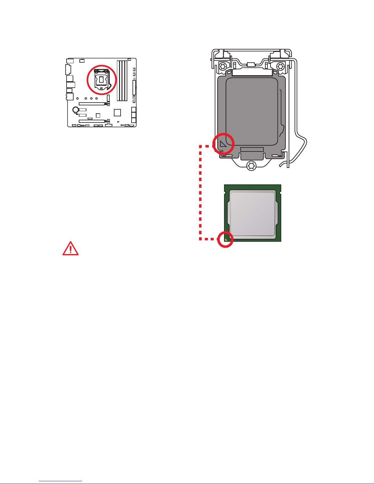
CPU Socket
Introduction to the LGA 1151 CPU
The surface of the LGA 1151 CPU has
two notches and a golden triangle to
assist in correctly lining up the CPU for
motherboard placement. The golden
triangle is the Pin 1 indicator.
Important
y
Always unplug the power cord from the power outlet before installing or removing
the CPU.
y
Please retain the CPU protective cap after installing the processor. MSI will deal
with Return Merchandise Authorization (RMA) requests if only the motherboard
comes with the protective cap on the CPU socket.
y
When installing a CPU, always remember to install a CPU heatsink. A CPU heatsink
is necessary to prevent overheating and maintain system stability.
y
Confirm that the CPU heatsink has formed a tight seal with the CPU before booting
your system.
y
Overheating can seriously damage the CPU and motherboard. Always make sure
the cooling fans work properly to protect the CPU from overheating. Be sure to
apply an even layer of thermal paste (or thermal tape) between the CPU and the
heatsink to enhance heat dissipation.
y
Whenever the CPU is not installed, always protect the CPU socket pins by covering
the socket with the plastic cap.
y
If you purchased a separate CPU and heatsink/ cooler, Please refer to the
documentation in the heatsink/ cooler package for more details about installation.
y
This motherboard is designed to support overclocking. Before attempting to
overclock, please make sure that all other system components can tolerate
overclocking. Any attempt to operate beyond product specifications is not
recommended. MSI® does not guarantee the damages or risks caused by
inadequate operation beyond product specifications.
Page 27
27
Overview of Components
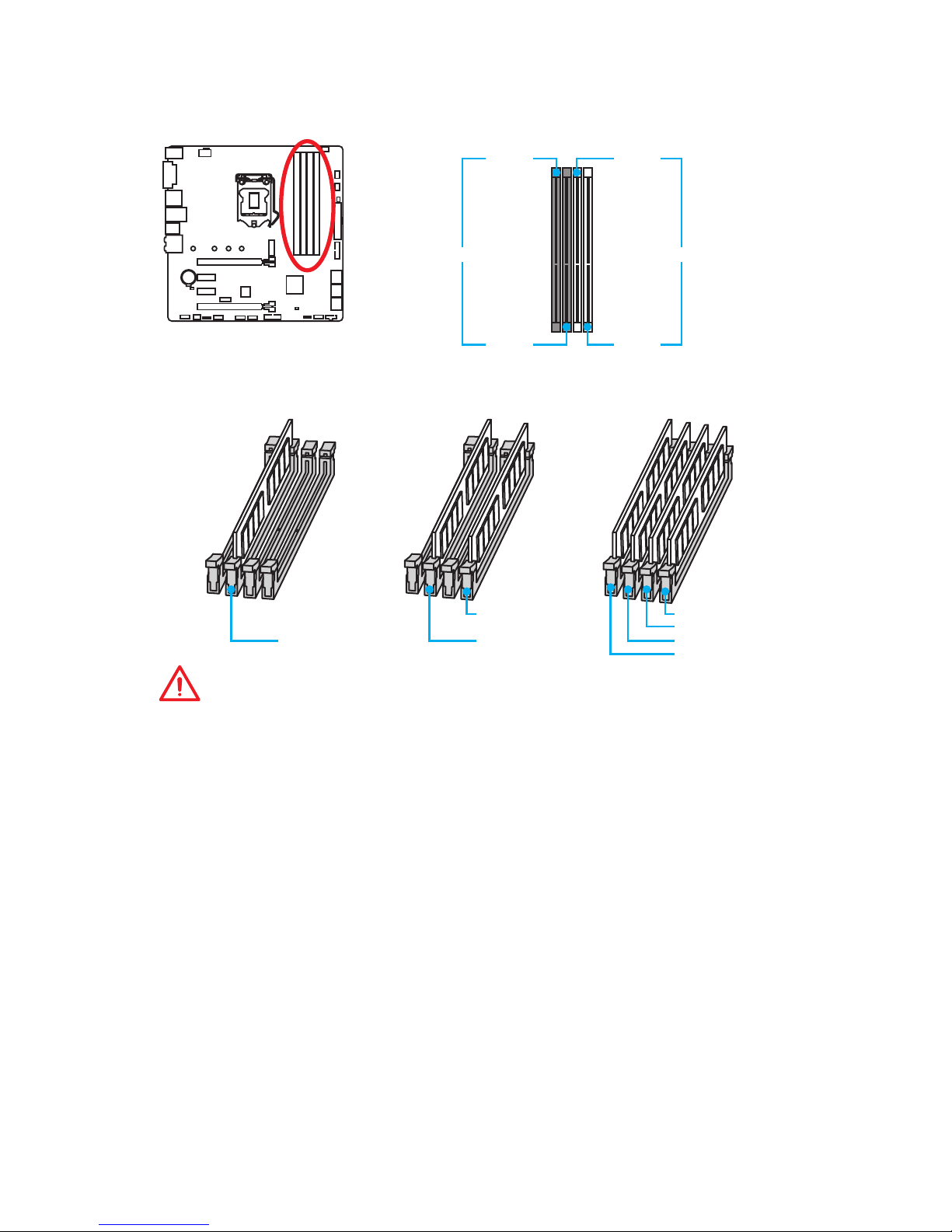
DIMM Slots
DIMMA1 DIMMB1
Channel A Channel B
DIMMA2 DIMMB2
Memory module installation recommendation
DIMMB2 DIMMB2
DIMMB1
DIMMA2 DIMMA2 DIMMA2
DIMMA1
Important
y
Always insert memory modules in the DIMMA2 slot first.
y
Due to chipset resource usage, the available capacity of memory will be a little less
than the amount of installed.
y
Based on Intel CPU specification, the Memory DIMM voltage below 1.35V is
suggested to protect the CPU.
y
Please note that the maximum capacity of addressable memory is 4GB or less
for 32-bit Windows OS due to the memory address limitation. Therefore, we
recommended that you to install 64-bit Windows OS if you want to install more than
4GB memory on the motherboard.
y
Some memory may operate at a lower frequency than the marked value when
overclocking due to the memory frequency operates dependent on its Serial
Presence Detect (SPD). Go to BIOS and find the Memory Try It! to set the memory
frequency if you want to operate the memory at the marked or at a higher
frequency.
y
It is recommended to use a more efficient memory cooling system for full DIMMs
installation or overclocking.
y
The stability and compatibility of installed memory module depend on installed CPU
and devices when overclocking.
Page 28
28
Overview of Components
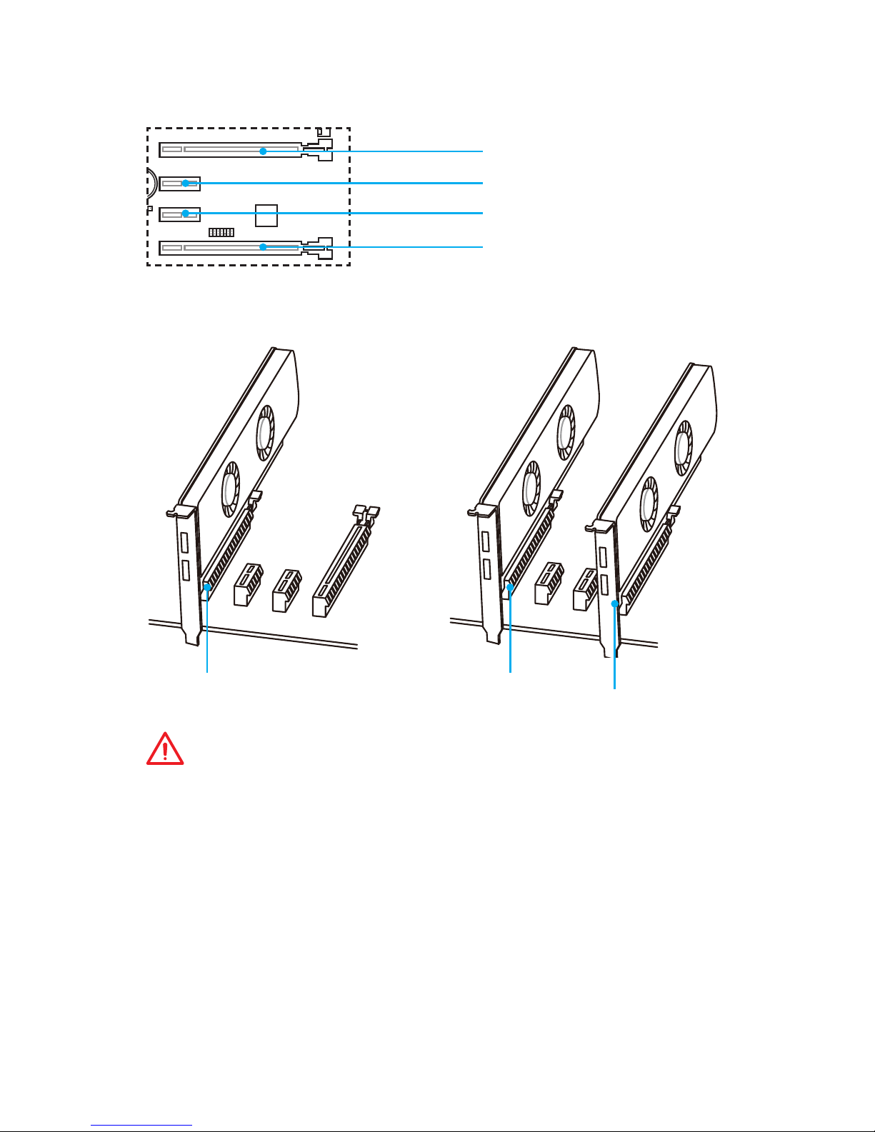
PCI_E1~4: PCIe Expansion Slots
PCI_E1: PCIe 3.0 x16
PCI_E2: PCIe 3.0 x1
PCI_E3: PCIe 3.0 x1
PCI_E4: PCIe 3.0 x4
x16 x16
x4
Multiple graphics cards installation recommendation
Important
y
For a single PCIe x16 expansion card installation with optimum performance, using
the PCI_E1 slot is recommended.
y
When adding or removing expansion cards, always turn off the power supply and
unplug the power supply power cable from the power outlet. Read the expansion
card’s documentation to check for any necessary additional hardware or software
changes.
y
If you install a large and heavy graphics card, you need to use a tool such as
MSI Gaming Series Graphics Card Bolster to support its weight and to prevent
deformation of the slot.
Page 29
29
Overview of Components
Important
y
Intel® RST only supports PCIe M.2 SSD with UEFI ROM.
y
Intel® OptaneTM Memory Ready.
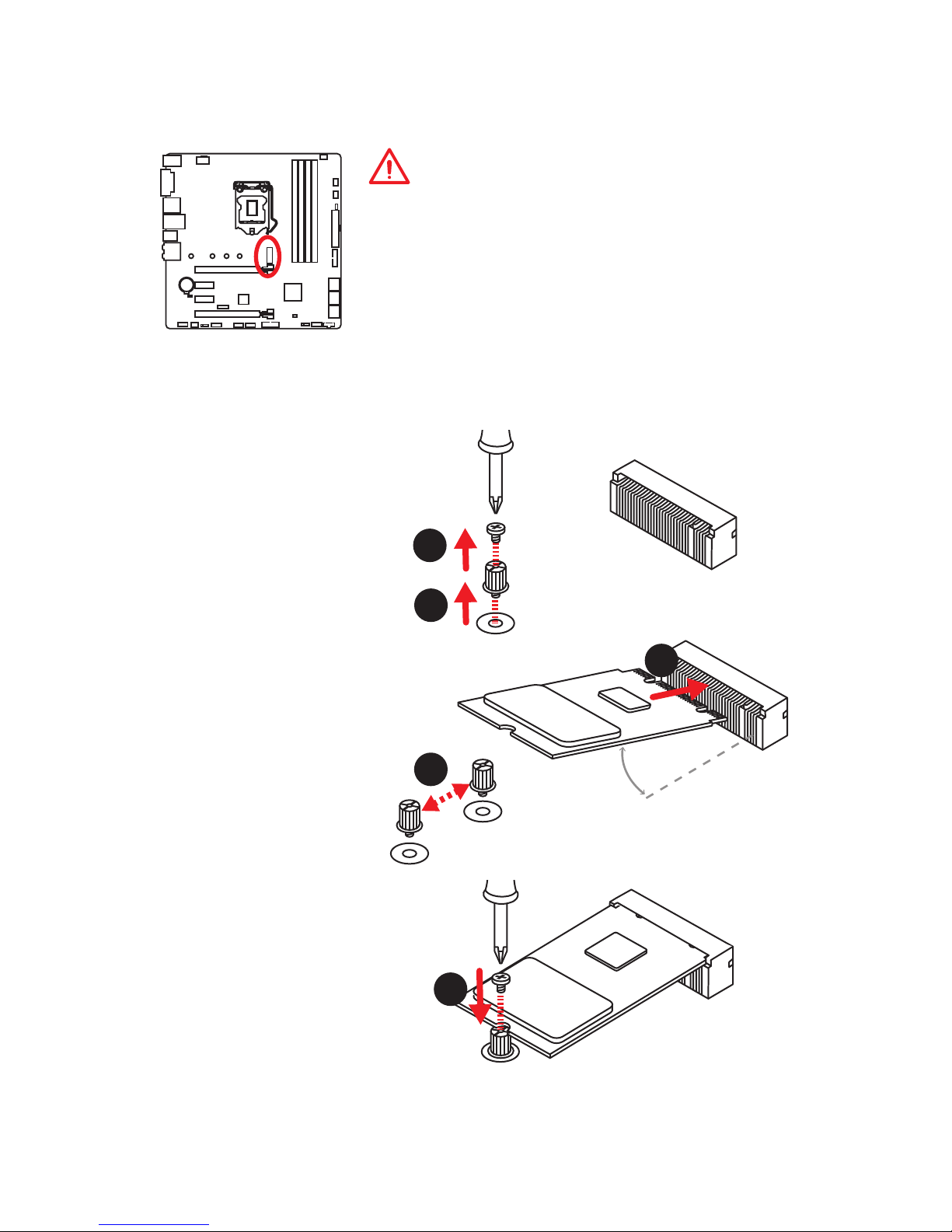
M2_1: M.2 Slot (Key M)
Installing M.2 module
1
2
3
30°
3. Tighten the base screw
into the hole of the
distance to the M.2 slot
as the length your M.2
module.
4. Insert your M.2 module
into the M.2 slot at a
30-degree angle.
5. Put the screw in the
notch on the trailing edge
of your M.2 module and
tighten it into the base
screw.
1. Remove the screw from
the base screw.
2. Remove the base screw.
4
5
Page 30

30
Overview of Components
SATA1~6: SATA 6Gb/s Connectors
These connectors are SATA 6Gb/s interface ports. Each connector can connect to one
SATA device.
SATA1
SATA2
SATA5
SATA6
SATA3
SATA4
Important
y
The SATA1 port will be unavailable when an M.2 SATA SSD module has been
installed in the M.2 slot.
y
Please do not fold the SATA cable at a 90-degree angle. Data loss may result during
transmission otherwise.
y
SATA cables have identical plugs on either sides of the cable. However, it is
recommended that the flat connector be connected to the motherboard for space
saving purposes.
M.2 & SATA combination table
Slot Available SATA connectors
M2_1 M.2 PCIe SSD M.2 SATA SSD Empty
SATA1 ✓ ─ ✓
SATA2 ✓ ✓ ✓
SATA3 ✓ ✓ ✓
SATA4 ✓ ✓ ✓
SATA5 ✓ ✓ ✓
SATA6 ✓ ✓ ✓
(✓: available, ─: unavailable)
M.2 slots with examples of various combination possibilities
PCIe
1xM.2 PCIe SSD + 6xSATA HDDs
SATA4 SATA2
SATA1SATA3
SATA
1xM.2 SATA SSD + 5xSATA HDDs
SATA3 SATA2
SATA4
SATA6
SATA6
SATA5
SATA5
Page 31

31
Overview of Components
1
2 10
9
1 DCD 2 SIN
3 SOUT 4 DTR
5 Ground 6 DSR
7 RTS 8 CTS
9 RI 10 No Pin
JCOM1: Serial Port Connector
This connector allows you to connect the optional serial port with bracket.
JFP1, JFP2: Front Panel Connectors
These connectors connect to the switches and LEDs on the front panel.
1
2 10
9
JFP1
1 HDD LED + 2 Power LED +
3 HDD LED - 4 Power LED 5 Reset Switch 6 Power Switch
7 Reset Switch 8 Power Switch
9 Reserved 10 No Pin
1
JFP2
1 Speaker - 2 Buzzer +
3 Buzzer - 4 Speaker +
JAUD1: Front Audio Connector
This connector allows you to connect audio jacks on the front panel.
1
2 10
9
1 MIC L 2 Ground
3 MIC R 4 NC
5 Head Phone R 6 MIC Detection
7 SENSE_SEND 8 No Pin
9 Head Phone L
10
Head Phone Detection
Page 32

32
Overview of Components
24
131
12
ATX_PWR1
1 +3.3V 13 +3.3V
2 +3.3V 14 -12V
3 Ground 15 Ground
4 +5V 16 PS-ON#
5 Ground 17 Ground
6 +5V 18 Ground
7 Ground 19 Ground
8 PWR OK 20 Res
9 5VSB 21 +5V
10 +12V 22 +5V
11 +12V 23 +5V
12 +3.3V 24 Ground
5
4 1
8
CPU_PWR1
1 Ground 5 +12V
2 Ground 6 +12V
3 Ground 7 +12V
4 Ground 8 +12V
Important
Make sure that all the power cables are securely connected to a proper ATX power
supply to ensure stable operation of the motherboard.
CPU_PWR1, ATX_PWR1: Power Connectors
These connectors allow you to connect an ATX power supply.
1
2 14
13
1 LPC Clock 2
3V Standby power
3 LPC Reset 4 3.3V Power
5
LPC address & data pin0
6 Serial IRQ
7
LPC address & data pin1
8 5V Power
9
LPC address & data pin2
10 No Pin
11
LPC address & data pin3
12 Ground
13 LPC Frame 14 Ground
JTPM1: TPM Module Connector
This connector is for TPM (Trusted Platform Module). Please refer to the TPM security
platform manual for more details and usages.
Page 33

33
Overview of Components
JUSB3~4: USB 3.1 Gen1 Connectors (optional)
These connectors allow you to connect USB 3.1 Gen1 ports on the front panel.
JUSB3
(For Z270 chipset)
1 10
1120
JUSB4
1
10 11
20
1 Power 11 USB2.0+
2 USB3_RX_DN 12 USB2.0-
3 USB3_RX_DP 13 Ground
4 Ground 14 USB3_TX_C_DP
5 USB3_TX_C_DN 15 USB3_TX_C_DN
6 USB3_TX_C_DP 16 Ground
7 Ground 17 USB3_RX_DP
8 USB2.0- 18 USB3_RX_DN
9 USB2.0+ 19 Power
10 GND 20 No Pin
Important
Note that the Power and Ground pins must be connected correctly to avoid possible
damage.
JUSB1~2: USB 2.0 Connectors
These connectors allow you to connect USB 2.0 ports on the front panel.
1
2 10
9
1 VCC 2 VCC
3 USB0- 4 USB1-
5 USB0+ 6 USB1+
7 Ground 8 Ground
9 No Pin 10 NC
Important
y
Note that the VCC and Ground pins must be connected correctly to avoid possible
damage.
y
In order to recharge your iPad,iPhone and iPod through USB ports, please install
MSI® SUPER CHARGER utility.
Page 34

34
Overview of Components
CPU_FAN1,SYS_FAN1~3: Fan Connectors
Fan connectors can be classified as PWM (Pulse Width Modulation) Mode or DC Mode.
PWM Mode fan connectors provide constant 12V output and adjust fan speed with
speed control signal. DC Mode fan connectors control fan speed by changing voltage.
When you plug a 3-pin (Non-PWM) fan to a fan connector in PWM mode, the fan speed
will always maintain at 100%, which might create a lot of noise. You can follow the
instruction below to adjust the fan connector to PWM or DC Mode.
PWM Mode pin definition
1 Ground 2 +12V
3 Sense 4 Speed Control Signal
DC Mode pin definition
1 Ground 2 Voltage Control
3 Sense 4 NC
Default PWM Mode fan connector
Default DC Mode fan connectors
Switching fan mode and adjusting fan speed
You can switch between PWM mode and DC mode and adjust fan speed in BIOS >
HARDWARE MONITOR.
Select PWM mode or DC mode
Important
Make sure fans are working properly after switching the PWM/ DC mode.
There are gradient points of the fan speed that allow you to adjust
fan speed in relation to CPU temperature.
1
CPU_FAN1
1
SYS_FAN1
1
SYS_FAN2/ SYS_FAN3
Pin definition of fan connectors
Page 35

35
Overview of Components
JCI1: Chassis Intrusion Connector
This connector allows you to connect the chassis intrusion switch cable.
Normal
(default)
Trigger the chassis
intrusion event
Using chassis intrusion detector
1. Connect the JCI1 connector to the chassis intrusion switch/ sensor on the chassis.
2. Close the chassis cover.
3. Go to BIOS > SETTINGS > Security > Chassis Intrusion Configuration.
4. Set Chassis Intrusion to Enabled.
5. Press F10 to save and exit and then press the Enter key to select Yes.
6. Once the chassis cover is opened again, a warning message will be displayed on
screen when the computer is turned on.
Resetting the chassis intrusion warning
1. Go to BIOS > SETTINGS > Security > Chassis Intrusion Configuration.
2. Set Chassis Intrusion to Reset.
3. Press F10 to save and exit and then press the Enter key to select Yes.
JBAT1: Clear CMOS (Reset BIOS) Jumper
There is CMOS memory onboard that is external powered from a battery located on
the motherboard to save system configuration data. If you want to clear the system
configuration, set the jumper to clear the CMOS memory.
Keep Data
(default)
Clear CMOS/
Reset BIOS
Resetting BIOS to default values
1. Power off the computer and unplug the power cord
2. Use a jumper cap to short JBAT1 for about 5-10 seconds.
3. Remove the jumper cap from JBAT1.
4. Plug the power cord and power on the computer.
Page 36

36
Overview of Components
JLED1: RGB LED connector
This connector allows you to connect the 5050 RGB LED strips.
Important
y
This connector supports 5050 RGB multi-color LED strips (12V/G/R/B) with the
maximum power rating of 3A (12V). Please keeping the LED strip shorter than 2
meters to prevent dimming.
y
Always turn off the power supply and unplug the power cord from the power outlet
before installing or removing the RGB LED strip.
y
Please use GAMING APP to control the extended LED strip
1
1 +12V 2 G
3 R 4 B
1
JLED1
5050 LED strip
EZ Debug LEDs
These LEDs indicate the status of key components during booting process. When an
error is occurred, the corresponding LED stays lit until the problem is solved.
CPU - indicates CPU is not detected or fail.
DRAM - indicates DRAM is not detected or fail.
VGA - indicates GPU is not detected or fail.
BOOT - indicates the booting device is not detected
or fail.
Page 37

37
BIOS Setup
BIOS Setup
The default settings offer the optimal performance for system stability in normal
conditions. You should always keep the default settings to avoid possible system
damage or failure booting unless you are familiar with BIOS.
Important
y
BIOS items are continuously update for better system performance. Therefore,
the description may be slightly different from the latest BIOS and should be for
reference only. You could also refer to the HELP information panel for BIOS item
description.
y
The pictures in this chapter are for reference only and may vary from the product
you purchased.
Entering BIOS Setup
Please refer the following methods to enter BIOS setup.
y Press Delete key, when the Press DEL key to enter Setup Menu, F11 to enter Boot
Menu message appears on the screen during the boot process.
y Use MSI FAST BOOT application. Click on GO2BIOS button and choose OK. The
system will reboot and enter BIOS setup directly.
Click on GO2BIOS
Function key
F1: General Help
F2: Add/ Remove a favorite item
F3: Enter Favorites menu
F4: Enter CPU Specifications menu
F5: Enter Memory-Z menu
F6: Load optimized defaults
F7: Switch between Advanced mode and EZ mode
F8: Load Overclocking Profile
F9: Save Overclocking Profile
F10: Save Change and Reset*
F12: Take a screenshot and save it to USB flash drive (FAT/ FAT32 format only).
* When you press F10, a confirmation window appears and it provides the modification
information. Select between Yes or No to confirm your choice.
Page 38

38
BIOS Setup
Resetting BIOS
You might need to restore the default BIOS setting to solve certain problems. There are
several ways to reset BIOS:
y Go to BIOS and press F6 to load optimized defaults.
y Short the Clear CMOS jumper on the motherboard.
Important
Be sure the computer is off before clearing CMOS data. Please refer to the Clear
CMOS jumper section for resetting BIOS.
Updating BIOS
Updating BIOS with M-FLASH
Before updating:
Please download the latest BIOS file that matches your motherboard model from MSI
website. And then save the BIOS file into the USB flash drive.
Updating BIOS:
1. Press Del key to enter the BIOS Setup during POST.
2. Insert the USB flash drive that contains the update file into the computer.
3. Select the M-FLASH tab and click on Yes to reboot the system and enter the flash
mode.
4. Select a BIOS file to perform the BIOS update process.
5. After the flashing process is 100% completed, the system will reboot
automatically.
Updating the BIOS with Live Update 6
Before updating:
Make sure the LAN driver is already installed and the Internet connection is set
properly.
Updating BIOS:
1. Install and launch MSI LIVE UPDATE 6.
2. Select BIOS Update.
3. Click on Scan button.
4. Click on
icon to download and install the latest BIOS file.
5. Click Next and choose In Windows mode. And then click Next and Start to start
updating BIOS.
6. After the flashing process is 100% completed, the system will restart
automatically.
Page 39

39
BIOS Setup
EZ Mode
At EZ mode, it provides the basic system information and allows you to configure the
basic setting. To configure the advanced BIOS settings, please enter the Advanced
Mode by pressing the Setup Mode switch or F7 function key.
Information
display
XMP switch
System
information
Boot device
priority bar
Function
buttons
Language
GAME BOOST
switch
Search
Screenshot
Setup Mode switch
M-Flash
Hardware
Monitor
Favorites
y GAME BOOST switch (for Z270 chipset only)- click on it to toggle the GAME BOOST
for OC.
Important
Please don’t make any changes in OC menu and don’t load defaults to keep the
optimal performance and system stability after activating the GAME BOOST function.
y XMP switch - click on the inner circle to enable/ disable the X.M.P. (Extreme Memory
Profile). Switch the outer circle to select the X.M.P. profile. This switch will only be
available if the X.M.P. supported memory module is installed.
y Setup Mode switch - press this tab or the F7 key to switch between Advanced mode
and EZ mode.
y Screenshot - click on this tab or the F12 key to take a screenshot and save it to USB
flash drive (FAT/ FAT32 format only).
y Search - click on this tab or the Ctrl+F keys and the search page will show. It allows
you to search by BIOS item name, enter the item name to find the item listing. Move
the mouse over a blank space and right click the mouse to exit search page.
Important
In search page, only the F6, F10 and F12 function keys are available.
y Language - allows you to select the language of BIOS setup.
y System information - shows the CPU/ DDR speed, CPU/ MB temperature, MB/ CPU
type, memory size, CPU/ DDR voltage, BIOS version and build date.
y Boot device priority bar - you can move the device icons to change the boot priority.
The boot priority from high to low is left to right.
Page 40

40
BIOS Setup
y Information display - click on the CPU, Memory, Storage, Fan Info and Help
buttons on left side to display related information.
y Function buttons - enable or disable the LAN Option ROM, M.2 Genie, HD audio
controller, AHCI, RAID, CPU Fan Fail Warning Control and BIOS Log Review by
clicking on their respective button.
y M-Flash - click on this button to display the M-Flash menu that provides the way to
update BIOS with a USB flash drive.
y Hardware Monitor - click on this button to display the Hardware Monitor menu that
allows you to manually control the fan speed by percentage.
y Favorites - click on this button or press the F3 key to enter Favorites menu. It
allows you to create personal BIOS menu where you can save and access favorite/
frequently-used BIOS setting items.
Default HomePage - allows you to select a BIOS menu (e.g. SETTINGS, OC...,etc)
as the BIOS home page.
Favorite1~5 - allows you to add the frequently-used/ favorite BIOS setting items in
one page.
To add a BIOS item to a favorite page (Favorite 1~5)
1. Move the mouse over a BIOS item not only on BIOS menu but also on search
page.
2. Right-click or press F2 key.
3. Choose a favorite page and click on OK.
To delete a BIOS item from favorite page
1. Move the mouse over a BIOS item on favorite page (Favorite 1~5)
2. Right-click or press F2 key.
3. Choose Delete and click on OK.
Page 41

41
BIOS Setup
Advanced Mode
Press Setup Mode switch or F7 function key can switch between EZ Mode and
Advanced Mode in BIOS setup.
GAME BOOST
switch
XMP switch
System
information
Boot device
priority bar
BIOS menu
selection
Language
Search
Screenshot
Setup Mode switch
Menu display
BIOS menu
selection
y GAME BOOST switch/ XMP switch/ Setup Mode switch/ Screenshot/ Language/
System information/ Boot device priority bar - please refer to the descriptions of
EZ Mode Overview section.
y BIOS menu selection - the following options are available:
SETTINGS - allows you to specify the parameters for chipset and boot devices.
OC - allows you to adjust the frequency and voltage. Increasing the frequency may
get better performance.
M-FLASH - provides the way to update BIOS with a USB flash drive.
OC PROFILE - allows you to manage overclocking profiles.
HARDWARE MONITOR - allows you to set the speeds of fans and monitor voltages
of system.
BOARD EXPLORER - provides the information of installed devices on this
motherboard.
y Menu display - provides BIOS setting items and information to be configured.
Page 42

42
BIOS Setup
SETTINGS
System Status
f System Date
Sets the system date. Use tab key to switch between date elements.
The format is <day> <month> <date> <year>.
<day> Day of the week, from Sun to Sat, determined by BIOS. Read-only.
<month> The month from Jan. through Dec.
<date> The date from 1 to 31 can be keyed by numeric function keys.
<year> The year can be adjusted by users.
f System Time
Sets the system time. Use tab key to switch between time elements.
The time format is <hour> <minute> <second>.
f SATA PortX/ M2_X
Shows the information of connected SATA/ M.2 devices.
Important
If the connected SATA device is not displayed, turn off computer and re-check SATA
cable and power cable connections of the device and motherboard.
f System Information
Shows detailed system information, including CPU type, BIOS version, and Memory
(read only).
f DMI Information
Shows system information, desktop Board Information and chassis Information. (Read
only).
Advanced
f PCI Subsystem Settings
Sets PCI, PCI express interface protocol and latency timer. Press Enter to enter the
sub-menu.
Page 43

43
BIOS Setup
fPEG X - Max Link Speed [Auto]
Sets PCI Express protocol of PCIe x16 slots for matching different installed devices.
[Auto] This item will be configured automatically by BIOS.
[Gen1] Enables PCIe Gen1 support only.
[Gen2] Enables PCIe Gen2 support only.
[Gen3] Enables PCIe Gen3 support only.
fPCI Latency Timer [32]
Sets latency timer of PCI interface device.
[Options: 32, 64, 96, 128, 160, 192, 224, 248 PCI Bus clocks]
fAbove 4G Decoding [Disabled]
Enables or disables 64-bit capable devices to be decoded in above 4G address
space. It is only available if the system supports 64-bit PCI decoding.
f ACPI Settings
Sets ACPI parameters of onboard power LED behaviors. Press Enter to enter the submenu.
fPower LED [Blinking]
Sets shining behaviors of the onboard Power LED.
[Dual Color] The power LED turns to another color to indicate the S3 state.
[Blinking] The power LED blinks to indicate the S3 state.
f Integrated Peripherals
Sets integrated peripherals' parameters, such as LAN, HDD, USB and audio. Press
Enter to enter the sub-menu.
fOnboard LAN Controller [Enabled]
Enables or disables the onboard LAN controller.
fLAN Option ROM [Disabled]
Enables or disables the legacy network Boot Option ROM for detailed settings. This
item will appear when Onboard LAN Controller is enabled.
[Enabled] Enables the onboard LAN Boot ROM.
[Disabled] Disables the onboard LAN Boot ROM.
fNetwork Stack [Disabled]
Sets UEFI network stack for optimizing IPv4 / IPv6 function.
[Enabled] Enables UEFI network stack.
[Disabled] Disables UEFI network stack.
fIpv4 PXE Support [Enabled]
When Enabled, the system UEFI network stack will support Ipv4 protocol. This item
will appear when Network Stack is enabled.
[Enabled] Enables the Ipv4 PXE boot support.
[Disabled] Disables the Ipv4 PXE boot support.
Page 44

44
BIOS Setup
fIpv6 PXE Support [Enabled]
When Enabled, the system UEFI network stack will support Ipv6 protocol. This item
will appear when Network Stack is enabled.
[Enabled] Enables the Ipv6 PXE boot support.
[Disabled] Disables the Ipv6 PXE boot support.
fSATA Mode [AHCI Mode]
Sets the operation mode of the onboard SATA controller.
[AHCI Mode] Specify the AHCI mode for SATA storage devices. AHCI (Advanced
Host Controller Interface) offers some advanced features to enhance
the speed and performance of SATA storage device, such as Native
Command Queuing (NCQ) and hot-plugging.
[RAID Mode] Enables RAID function for SATA storage devices.
fM2_1-RST Pcie Storage Remapping [Disabled]
Enables or disables Intel Rapid Storage Technology for M.2 PCIe device.
fM.2 Genie [Disabled]
Enables or disables M.2 SSDs to build RAID 0 volume.
fSATAx Hot Plug [Disabled]
Allows user to enable or disable the SATA hot plug support.
[Enabled] Enables hot plug support for the SATA ports.
[Disabled] Disables hot plug support for the SATA ports.
fHD Audio Controller [Enabled]
Enables or disables the onboard High Definition Audio controller.
fHPET [Enabled]
Enables or disables the HPET (High Precision Event Timers) support.
fIntel Serial I/O [Disabled]
Enables or disables the supported devices to transfer data with Intel serial
protocol.
f Integrated Graphics Configuration
Adjusts integrated graphics settings for optimum system. Press Enter to enter the
sub-menu.
fInitiate Graphic Adapter [PEG]
Selects a graphics device as the primary boot device.
[IGD] Integrated Graphics Display.
[PEG] PCI-Express Graphics Device.
fIntegrated Graphics Share Memory [64M]
Selects a fixed amount of system memory allocated to the onboard graphics. This
item will appear when IGD Multi-Monitor is enabled.
Page 45

45
BIOS Setup
fIGD Multi-Monitor [Disabled]
Enables or disables the multi-screen output from integrated graphics and external
graphics card. This item appears when Initiate Graphic Adapter set to PEG.
[Enabled] Enables multi-screen function for both integrated and external
graphics cards.
[Disabled] Disables this function.
f USB Configuration
Sets the onboard USB controller and device function. Press Enter to enter the submenu.
fUSB Controller [Enabled]
Enables or disables all USB controller.
fXHCI Hand-off [Diasbled]
Enables or disables XHCI hand-off support for the operating system without XHCI
hand-off feature.
fLegacy USB Support [Enabled]
Sets Legacy USB function support.
[Auto] The system will automatically detect if any USB device is connected
and enable the legacy USB support.
[Enabled] Enable the USB support under legacy mode.
[Disabled] The USB devices will be unavailable under legacy mode.
f Super IO Configuration
Sets system Super I/O chip parameters including LPT and COM ports. Press Enter to
enter the sub-menu.
fSerial (COM) Port 0 Configuration
Sets detailed configuration of serial(COM) port 0. Press Enter to enter the submenu.
fSerial (COM) Port 0 [Enabled]
Enables or disables serial (COM) port 0.
fSerial (COM) Port 0 Settings [Auto]
Sets serial port 0 (COM). If set to Auto, BIOS will optimize the IRQ automatically or
you can set it manually.
f Power Management Setup
Sets system Power Management of EuP2013 and AC Power Loss behaviors. Press
Enter to enter the sub-menu.
fEuP 2013 [Disabled]
Enables or disables the system power consumption according to EuP2013
regulation.
[Enabled] Optimize the system power consumption according to EuP 2013
regulation. It will not support S4 & S5 wake up by USB, PCI and PCIe
devices.
[Disabled] Disables this function.
Page 46

46
BIOS Setup
fRestore after AC Power Loss [Power Off]
Sets the system behaviors while encountering the AC power loss.
[Power Off] Leaves the system in power off state after restoring AC power.
[Power On] Boot up the system after restoring AC power.
[Last State] Restores the system to the previous state (power on/ power off)
before AC power loss.
fSystem Power Fault Protection [Disabled]
Enables or disables the system to boot up when detecting abnormal voltage input.
[Enabled] Protect the system from unexpected power operation and remain
the shut down status.
[Disabled] Disables this function.
f Windows OS Configuration
Sets Windows OS detailed configuration and behaviors. Press Enter to enter the submenu.
fWindows 8.1/ 10 WHQL Support [Disabled]
Enables the supports for Windows 8.1/ 10 or disables for other operating systems.
Before enabling this item, make sure all installed devices & utilities (hardware &
software) should meet the Windows 8.1/ 10 requirements.
[Enabled] The system will switch to UEFI mode to meet the Windows
equirement.
[Disabled] Disables this function.
fMSI Fast Boot [Disabled]
MSI Fast Boot is the fastest way to boot the system. It will disable more devices to
speed up system boot time which is faster than the boot time of Fast Boot.
[Enabled] Enables the MSI Fast Boot function to speed up booting time. And
the following Fast Boot field will be disabled and fixed.
[Disabled] Disables MSI Fast Boot.
Important
When MSI Fast Boot is enabled, you can use MSI FAST BOOT application to enter BIOS
setup if needed. Please refer Entering BIOS Setup section for details.
fFast Boot [Enabled/ windows 8.1/ 10, Disabled/ windows7]
Enables or disables the fast boot feature for Windows 8.1/ 10. This item will only be
available when MSI Fast Boot is disabled.
[Enabled] Enables the Fast Boot configuration to accelerate system boot time.
[Disabled] Disables the Fast Boot configuration.
fInternal GOP Configuration
Manages the onboard Graphics Output Protocol (GOP). Press Enter to enter the
sub-menu. This sub-menu will appear when Windows 8.1/ 10 WHQL Support is
enabled.
fSecure Boot
Sets the Windows secure boot to prevent the unauthorized accessing. Press Enter
to enter the sub-menu. This sub-menu will appear when Windows 8.1/ 10 WHQL
Support is enabled.
Page 47

47
BIOS Setup
fSecure Boot Support [Disabled]
Enables or disables secure boot support.
[Enabled] Enables the secure boot function and allow you to set the secure
boot settings.
[Disabled] Disables this function.
fSecure Boot Mode [Standard]
Selects the secure boot mode. This item is to select how the secure boot keys be
loaded. This item appears when Secure Boot Support is enabled.
[Standard] The system will automatically load the secure keys from BIOS.
[Custom] Allows user to configure the secure boot settings and manually load
the secure keys.
fKey Management
Manages the secure boot keys. Press <Enter> to enter the sub-menu. This submenu will appear when Secure Boot Mode sets to Custom.
f Wake Up Event Setup
Sets system wake up behaviors for different sleep modes. Press Enter to enter the
sub-menu.
fWake Up Event By [BIOS]
Selects the wake up event by BIOS or operating system.
[BIOS] Activates the following items, set wake up events of these items.
[OS] The wake up events will be defined by OS.
fResume By RTC Alarm [Disabled]
Disables or enables the system wake up by RTC Alarm.
[Enabled] Enables the system to boot up on a scheduled time/ date.
[Disabled] Disables this function.
fDate (of month) Alarm/ Time (hh:mm:ss) Alarm
Sets RTC alarm date/ Time. If Resume By RTC Alarm is set to [Enabled], the system
will automatically resume (boot up) on a specified date/hour/minute/second in
these fields (using the + and - keys to select the date & time settings).
fResume By PCI-E Device [Disabled]
Enables or disables the wake up function of installed PCI-E expansion cards,
integrated LAN controllers or USB devices which are supported by third party
integrated chips.
[Enabled] Enables the system to be awakened from the power saving modes
when activity or input signal of PCIe device is detected.
[Disabled] Disables this function.
fResume By Onboard Intel LAN [Disabled]
Enables or disables the system wake up by Onboard Intel LAN.
[Enabled] Enables the system to be awakened from the power saving modes
when activity or input signal of Intel LAN device is detected.
[Disabled] Disables this function.
Page 48

48
BIOS Setup
fResume by USB Device [Disabled]
Enables or disables the system wake up by USB devices.
[Enabled] Enables the system to be awakened from sleep state when activity of
USB device is detected.
[Disabled] Disables this function.
fResume From S3/S4/S5 by PS/2 Mouse [Disabled]
Enables or disables the system wake up by PS/2 mouse.
[Enabled] Enables the system to be awakened from S3/ S4/ S5 state when
activity of PS/2 mouse is detected.
[Disabled] Disables this function.
fResume From S3/S4/S5 by PS/2 Keyboard [Disabled]
Enables or disables the system wake up by PS/2 keyboard.
[Any Key] Enables the system to be awakened from S3/ S4/ S5 state when
activity of any key on PS/2 keyboard is detected.
[Hot Key] Enables the system to be awakened from S3/ S4/ S5 state when
activity of hot key on PS/2 keyboard is detected.
[Disabled] Disables this function.
fHot Key [Ctrl+Space]
Selects a combination of keys as a hot key to wake the system. This item appears
when you set the Resume From S3/S4/S5 by PS/2 Keyboard to Hot Key.
f Secure Erase+
Enables or disables Secure Erase+ function. Secure Erase+ is the best way to
effectively wipe all data from a SSD. Please note that data of SSD will be erased after
enabling Secure Erase+.
Boot
Sets the sequence of system boot devices.
f Full Screen Logo Display [Enabled]
Enables or disables to show the full screen logo while system POST.
[Enabled] Shows the logo in full screen.
[Disabled] Shows the POST messages.
f GO2BIOS [Disabled]
Allows system to enter BIOS setup directly by pressing the Power button for 4 sec pon
bootup.
[Enabled] The system boots straight to the BIOS setup by long pressing the power
button about 4 seconds when the system is off.
[Disabled] Disables this function.
f Bootup NumLock State [On]
Select the keyboard NumLock state upon bootup.
Page 49

49
BIOS Setup
f Info Block effect [Unlock]
Sets the state of Help information block.
[Unlock] Sliding effect.
[Lock] Fix the Help information block on the screen.
f AUTO CLR_CMOS [Disabled]
Enables or disables the CMOS data to be resumed automatically when the booting
process hang-up over 5 seconds.
f Boot Mode Select [LEGACY+UEFI]
Sets the system boot mode from legacy or UEFI architecture depending on OS
installation requirement. This item will become un-selectable and will be configured
automatically by BIOS when Windows 8.1/ 10 WHQL Support is enabled.
[UEFI] Enables UEFI BIOS boot mode support only.
[LEGACY+UEFI] Enables both Legacy BIOS boot mode and UEFI BIOS boot
mode.
f FIXED BOOT ORDER Priorities
Sets device priority for system boot.
f Boot Option Priorities
These items are used to prioritize the installed boot devices.
Security
f Administrator Password
Sets administrator password for system security. User has full rights to change the
BIOS items with administrator password. After setting the administrator password, the
state of this item will show “Installed”.
f User Password
Sets User Password for system security. User has limited rights to change the BIOS
items with user password. This item will be available when administrator password is
set. After setting the user password, the state of this item will show “Installed”.
f Password Check [Setup]
Selects a condition that will request the password.
[Setup] A password will be requested for entering the BIOS Setup.
[Boot] A password will be requested for booting the system.
f Password Clear [Enabled]
Enables or disables the clear CMOS behavior to clear a set password.
[Enabled] The password will be erased after clear CMOS.
[Disabled] The password will always be kept.
Important
When selecting the Administrator / User Password items, a password box will appear
on the screen. Type the password then press <Enter>. The password typed now will
replace any previous set password from CMOS memory. You will be prompted to
confirm the password. You may also press <Esc> to abort the selection.
Page 50

50
BIOS Setup
To clear a set password, press <Enter> when you are prompted to enter a new
password. A message will confirm the password is being disabled. Once the password
is disabled, you can enter the setup and OS without authorization.
f Trusted Computing
Sets TPM (Trusted Platform Module) function.
fSecurity Device Support [Disabled]
Enables or disables the TPM function to build the endorsement key for accessing
the system.
fTPM Device Selection [PTT]
Selects TPM device: PTT or dTPM.
[PTT] Select it for Intel Platform Trust technology
[dTPM] Select it for installed TPM device.
f Chassis Intrusion Configuration
Press <Enter> to enter the sub-menu.
fChassis Intrusion [Disabled]
Enables or disables recording messages when the chassis is opened. This function
is ready for the chassis equips a chassis intrusion switch.
[Enabled] Once the chassis is opened, the system will record and issue a
warning message.
[Reset] Clear the warning message. After clearing the message, please
return to Enabled or Disabled.
[Disabled] Disables this funcion.
Save & Exit
f Discard Changes and Exit
Exit BIOS setup without saving any change.
f Save Changes and Reboot
Save all changes and reboot the system.
f Save Changes
Save current changes.
f Discard Changes
Discard all changes and restore to the previous values.
f Restore Defaults
Restore or load all default values.
f Boot Override
The installed bootable devices will appear on this menu, you can select one of them to
be the boot device.
Page 51

51
BIOS Setup
OC
Important
y
Overclocking your PC manually is only recommended for advanced users.
y
Overclocking is not guaranteed, and if done improperly, it could void your warranty
or severely damage your hardware.
y
If you are unfamiliar with overclocking, we advise you to use GAME BOOST function
for easy overclocking.
y
The BIOS items in OC menu will vary with the chipset.
f OC Explore Mode [Normal]
Enables or disables to show the normal or expert version of OC settings.
[Normal] Provides the regular OC settings in BIOS setup.
[Expert] Provides the advanced OC settings for OC expert to configure in BIOS
setup.
Note: We use * as the symbol for the OC settings of Expert mode.
f CPU Ratio Apply Mode [All Core]*
Sets applied mode for CPU ratio. This item only appears when a CPU that supports
Turbo Boost is installed.
[All Core] Activate the CPU Ratio field. All CPU cores will run the same CPU ratio
that be set in CPU Ratio.
[Per Core] Activate the X-Core Ratio Limit field. Sets each CPU core ratio
separately in X-Core Ratio Limit.
f CPU Ratio [Auto]
Sets the CPU ratio that is used to determine CPU clock speed. This item can only be
changed if the processor supports this function.
f 1/2/3/4-Core Ratio Limit [Auto]*
Allows you to set the CPU ratios for different number of active cores. These items only
appear when a CPU that support this function is installed.
Page 52

52
BIOS Setup
f Adjusted CPU Frequency
Shows the adjusted CPU frequency. Read-only.
f CPU Ratio Offset When Running AVX [Auto]*
Sets a offset value to lower the CPU core ratio. It could be helpful for heat dissipation
when running AVX instruction set. If set to Auto, BIOS will configure this setting
automatically. This item appears when the installed CPU supports this function.
f CPU Ratio Mode [Dynamic Mode]*
Selects the CPU Ratio operating mode. This item will appear when you set the CPU
ratio manually.
[Fixed Mode] Fixes the CPU ratio.
[Dynamic Mode] CPU ratio will be changed dynamically according to the CPU
loading.
f Ring Ratio [Auto]
Sets the ring ratio. The valid value range depends on the installed CPU.
f Adjusted Ring Frequency
Shows the adjusted Ring frequency. Read-only.
f GT Ratio [Auto]
Sets the integrated graphics ratio. The valid value range depends on the installed
CPU.
f Adjusted GT Frequency
Shows the adjusted integrated graphics frequency. Read-only.
f Misc Setting
Press Enter, + or - key to open or close the following 3 items related to CPU features.
fEIST [Enabled]
Enables or disables the Enhanced Intel
®
SpeedStep Technology.
[Enabled] Enables the EIST to adjust CPU voltage and core frequency
dynamically. It can decrease average power consumption and
average heat production.
[Disabled] Disables EIST.
fIntel Turbo Boost [Enabled]*
Enables or disables the Intel
®
Turbo Boost. This item appears when the installed
CPU supports this function.
[Enabled] Enables this function to boost CPU performance automatically above
rated specifications when system request the highest performance
state.
[Disabled] Disables this function.
f CPU Base Clock (MHz)
Sets the CPU Base clock. You may overclock the CPU by adjusting this value. Please
note that overclocking behavior and stability is not guaranteed. This item appears
when the installed processor supports this function.
Page 53

53
BIOS Setup
f CPU Base Clock Apply Mode [Auto]*
Sets the applying mode for adjusted CPU base clock.
[Auto] This setting will be configured automatically by BIOS.
[Next Boot] CPU will run the adjusted CPU base clock at next boot.
[Immediate] CPU runs the adjusted CPU base clock immediately.
[During Boot] CPU will run the adjusted CPU base clock during boot.
f Extreme Memory Profile (X.M.P.) [Disabled]
X.M.P. (Extreme Memory Profile) is the overclocking technology by memory module.
Please enable XMP or select a profile of memory module for overclocking the memory.
This item will be available when the memory modules that support X.M.P. is installed.
f DRAM Reference Clock [Auto]*
Sets the DRAM reference clock. The valid value range depends on the installed CPU.
This item appears when a CPU that supports this adjustment is installed.
f DRAM Frequency [Auto]
Sets the DRAM frequency. Please note the overclocking behavior is not guaranteed.
f Adjusted DRAM Frequency
Shows the adjusted DRAM frequency. Read-only.
f Memory Try It ! [Disabled]
It improve memory compatibility or performance by choosing optimized memory
preset.
f Advanced DRAM Configuration
Press Enter to enter the sub-menu. User can set the memory timing for each/ all
memory channel. The system may become un-stable or un-bootable after changing
memory timing. If it occurs, please clear the CMOS data and restore the default
settings. (Refer to the Clear CMOS jumper/ button section to clear the CMOS data, and
enter the BIOS to load the default settings.)
f Memory Fast Boot [Auto]*
Enables or disables the initiation and training for memory every booting.
[Auto] The setting will be configured automatically by BIOS.
[Enabled] System will completely keep the archives of first intiation and training
for memory. So the memory will not be initialed and trained when
booting to accelerate the system booting time.
[Disabled] The memory will be initialed and trained every booting.
f DigitALL Power
Press Enter to enter the sub-menu. Controls the digital powers related to CPU PWM.
fCPU Loadline Calibration Control [Auto]
Sets a specific CPU loadline calibration mode for full-loading system to get good
overclocking performance and stability. If set to Auto, BIOS will configure this
setting automatically.
Page 54

54
BIOS Setup
fCPU GT Loadline Calibration Control [Auto]
Sets a specific CPU-GT loadline calibration mode for full-loading system to get
good overclocking performance and stability. If set to Auto, BIOS will configure this
setting automatically.
f CPU Core/ GT Voltage Mode [Auto]*
Selects the control mode for CPU Core/ GT voltages.
[Auto] This setting will be configured automatically by BIOS.
[Adaptive Mode] Sets the adaptive voltage automatically for optimizing the system
performance.
[Override Mode] Allows you to set the voltage manually.
[Offset Mode] Allows you to set the offset voltage and select the voltage offset
mode.
[Adaptive + Offset ] Sets the adaptive voltage automatically and allows you to set the
offset voltage.
[Override + Offset ] Allows you to set the voltage and the offset voltage manually.
f CPU Voltages control [Auto]
These options allows you to set the voltages related to CPU. If set to Auto, BIOS will
set these voltages automatically or you can set it manually.
f DRAM Voltages control [Auto]
These options allows you to set the voltages related to memory. If set to Auto, BIOS
will set these voltages automatically or you can set it manually.
f PCH Voltage control [Auto]
The option allows you to set the PCH voltage. If set to Auto, BIOS will set these
voltages automatically or you can set it manually.
f OC Quick View Timer [3 Sec]*
Sets the duration of OC setting values showed on the screen.
f CPU Specifications
Press Enter to enter the sub-menu. This sub-menu displays the information of
installed CPU. You can also access this information menu at any time by pressing [F4].
Read only.
fCPU Technology Support
Press Enter to enter the sub-menu. The sub-menu shows the key features of
installed CPU. Read only.
f MEMORY-Z
Press Enter to enter the sub-menu. This sub-menu displays all the settings and
timings of installed memory. You can also access this information menu at any time by
pressing [F5].
fDIMM1~4 Memory SPD
Press Enter to enter the sub-menu. The sub-menu displays the information of
installed memory. Read only.
Page 55

55
BIOS Setup
f CPU Features
Press Enter to enter the sub-menu.
fHyper-Threading [Enabled]
Intel Hyper-Threading technology treats the multi cores inside the processor as
multi logical processors that can execute instructions simultaneously. In this way,
the system performance is highly improved. This item appears when the installed
CPU supports this technology.
[Enable] Enables Intel Hyper-Threading technology.
[Disabled] Disables this item if the system does not support HT function.
fActive Processor Cores Control [All]
Allows you to select the number of active CPU cores.
fLimit CPUID Maximum [Disabled]
Enables or disables the extended CPUID value.
[Enabled] BIOS limits the maximum CPUID input value to circumvent boot
problems with older operating system that do not support the
processor with extended CPUID value.
[Disabled] Use the actual maximum CPUID input value.
fIntel Virtualization Tech [Enabled]
Enables or disables Intel Virtualization technology.
[Enabled] Enables Intel Virtualization technology and allows a platform to run
multiple operating systems in independent partitions. The system
can function as multiple systems virtually.
[Disabled] Disables this function.
fIntel VT-D Tech [Disabled]
Enables or disables Intel VT-D (Intel Virtualization for Directed I/O) technology.
fHardware Prefetcher [Enabled]
Enables or disables the hardware prefetcher (MLC Streamer prefetcher).
[Enabled] Allows the hardware prefetcher to automatically pre-fetch data
and instructions into L2 cache from memory for tuning the CPU
performance.
[Disabled] Disables the hardware prefetcher.
fAdjacent Cache Line Prefetch [Enabled]
Enables or disables the CPU hardware prefetcher (MLC Spatial prefetcher).
[Enabled] Enables adjacent cache line prefetching for reducing the cache
latency time and tuning the performance to the specific application.
[Disabled] Enables the requested cache line only.
fCPU AES Instructions [Enabled]
Enables or disables the CPU AES (Advanced Encryption Standard-New
Instructions) support. This item appears when a CPU supports this function.
Page 56

56
BIOS Setup
fIntel Adaptive Thermal Monitor [Enabled]
Enables or disables the Intel adaptive thermal monitor function to protect the CPU
from overheating.
[Enabled] Throttles down the CPU core clock speed when the CPU is over the
adaptive temperature.
[Disabled] Disables this function.
fIntel C-State [Auto]
Enables or disables the Intel C-state. C-state is a processor power management
technology defined by ACPI.
[Auto] This setting will be configured automatically by BIOS.
[Enabled] Detects the idle state of system and reduce CPU power consumption
accordingly.
[Disabled] Disable this function.
fC1E Support [Disabled]
Enables or disables the C1E function for power-saving in halt state. This item
appears when Intel C-State is enabled.
[Enabled] Enables C1E function to reduce the CPU frequency and voltage for
power-saving in halt state.
[Disabled] Disables this function.
fPackage C State limit [Auto]
This item allows you to select a CPU C-state level for power-saving when system is
idle. The options of C-state depend on the installed CPU. This item appears when
Intel C-State is enabled.
fCFG Lock [Enabled]
Lock or un-lock the MSR 0xE2[15], CFG lock bit.
[Enabled] Locks the CFG lock bit.
[Disabled] Un-locks the CFG lock bit.
fEIST [Enabled]
Enables or disables the Enhanced Intel
®
SpeedStep Technology. This item will
appear when OC Explore Mode is set to Normal.
[Enabled] Enables the EIST to adjust CPU voltage and core frequency
dynamically. It can decrease average power consumption and
average heat production.
[Disabled] Disables EIST.
fIntel Turbo Boost [Enabled]
Enables or disables the Intel
®
Turbo Boost. This item is for Normal mode and
appears when a CPU that support Turbo Boost is installed.
[Enabled] Enables this function to boost CPU performance automatically over
specification when system request the highest performance state.
[Disabled] Disables this function.
Page 57

57
BIOS Setup
fLong Duration Power Limit (W) [Auto]
Sets the long duration TDP power limit for CPU in Turbo Boost mode.
fLong Duration Maintained (s) [Auto]
Sets the maintaining time for Long duration power Limit(W).
fShort Duration Power Limit (W) [Auto]
Sets the short duration TDP power limit for CPU in Turbo Boost mode.
fCPU Current Limit (A) [Auto]
Sets maximum current limit of CPU package in Turbo Boost mode. When the
current is over the specified value, the CPU will automatically reduce the core
frequency for reducing the current.
fFCLK Frequency [Auto]
Sets FCLK frequency. Lower FCLK frequency may help you to set higher base clock
frequency.
fDMI Link Speed [Auto]
Sets DMI speed.
fSW Guard Extensions (SGX) [Software Control]
Enables or disables Intel SGX.
Page 58

58
BIOS Setup
M-FLASH
M-FLASH provides the way to update BIOS with a USB flash drive. Please down-load
the latest BIOS file that matches your motherboard model from MSI website, save the
BIOS file into your USB flash drive. And then follow the steps below to update BIOS.
1. Insert the USB flash drive that contains the update file into the computer.
2. Click on M-FLASH tab, a demand message will be prompted. Click on Yes to
reboot and enter the flash mode.
3. The system will enter the flash mode and a file selection menu will appear after
rebooting.
4. Select a BIOS file to perform the BIOS update process.
5. After the flashing process is 100% completed, the system will reboot
automatically.
Page 59

59
BIOS Setup
OC PROFILE
f Overclocking Profile 1/ 2/ 3/ 4/ 5/ 6
Overclocking Profile 1/ 2/ 3/ 4/ 5/ 6 management. Press <Enter> to enter the submenu.
fSet Name for Overclocking Profile 1/ 2/ 3/ 4/ 5/ 6
Name the current overclocking profile.
fSave Overclocking Profile 1/ 2/ 3/ 4/ 5/ 6
Save the current overclocking profile.
fLoad Overclocking Profile 1/ 2/ 3/ 4/ 5/ 6
Load the current overclocking profile.
fClear Overclocking Profile 1/ 2/ 3/ 4/ 5/ 6
Clear the current overclocking profile.
f OC Profile Load from ROM
Load OC profile from BIOS ROM.
f OC Profile Save to USB
Save OC profile to the USB flash drive. The USB flash drive should be FAT/ FAT32
format only.
f OC Profile Load from USB
Load OC profile from the USB flash drive. The USB flash drive should be FAT/ FAT32
format only.
Page 60

60
BIOS Setup
HARDWARE MONITOR
Temperature
& Speed
Fan Manage
Voltage
display
Setting
Buttons
f Temperature & Speed
Shows the current CPU temperature, system temperature and fans' speeds.
f Fan Manage
PWM - allows you to select the PWM mode for fan operation.
DC - allows you to select the DC mode for fan operation.
Fan step up/ down time - allows you to set the period of fan step up/ down.
Smart Fan Mode field - allows you to drag the gradient points to configure the
fan target values for Smart Fan mode. Smart Fan can control the fan speed
automatically depending on the CPU temperature to keep it with in a specific
range. If the current CPU temperature reaches to the target value, the Smart Fan
function will be activated.
Important
y
The changing will achieve after you save the changes and reboot the system.
y
Make sure fans are working properly after switching the PWM/ DC mode.
f Settings Buttons
All Full Speed - configures all fans to run at full operating speed.
All Set Default - configures all fans to run at default operating speed.
All Set Cancel - discards current changes and restores previous operating fan
speeds .
f Voltage display
Shows the current voltages of CPU, system and memory.
Page 61

61
Software Description
Software Description
Please download and update the latest utilities and drivers
.
Installing Windows® 7/ 8.1/ 10
1. Power on the computer.
2. Insert the Windows
®
7/ 8.1/ 10 disc into your optical drive.
Note: Due to chipset limitation, during the Windows® 7 installation process, USB
optical drives or USB flash drives are not supported. You can use MSI Smart Tool
to install Windows® 7.
3. Press the Restart button on the computer case.
4. For windows 8.1/ 10, skip this step. For Windows
®
7, access the BIOS menu
SETTINGS > Advanced > Windows OS Configuration > Windows 7 Installation and
set the item to enabled, save changes and restart.
Note: It is suggested to plug in your USB Keyboard/ USB Mouse to the leftmost
USB port when installing Windows® 7.
5. Press F11 key during the computer POST (Power-On Self Test) to get into Boot
Menu.
6. Select your optical drive from the Boot Menu.
7. Press any key when screen shows Press any key to boot from CD or DVD...
message.
8. Follow the instructions on the screen to install Windows
®
7/ 8.1/ 10.
Installing Drivers
1. Start up your computer in Windows® 7/ 8.1/ 10.
2. Insert MSI
®
Driver Disc into your optical drive.
3. The installer will automatically appear and it will find and list all necessary
drivers.
4. Click Install button.
5. The software installation will then be in progress, after it has finished it will
prompt you to restart.
6. Click OK button to finish.
7. Restart your computer.
Installing Utilities
Before you install utilities, you must complete drivers installation.
1. Insert MSI
®
Driver Disc into your optical drive.
2. The installer will automatically appear.
3. Click Utilities tab.
4. Select the utilities you want to install.
5. Click Install button.
6. The utilities installation will then be in progress, after it has finished it will prompt
you to restart.
7. Click OK button to finish.
8. Restart your computer.
Page 62

62
Software Description
COMMAND CENTER
COMMAND CENTER is an user-friendly software and exclusively developed by MSI,
helping users to adjust system settings and monitor status under OS. With the help
of COMMAND CENTER, making it possible to achieve easier and efficient monitoring
process and adjustments than that under BIOS. In addition, the COMMAND CENTER
can be a server for mobile remote control application.
Feature Menu
CPU TemperatureSystem Information
Feature Title
Feature
Control Panel
Previous
Feature
Next Feature
Profile
Buttons
Option Buttons
Page Indicator
Resize Corner
Profile Buttons
y Default - load the default values for the current feature.
y Apply - apply your changes.
y Save - store values in the file with individual file extension.
y Load - load the values from the file.
Important
Every time you shut down the system, the configured setting will be restored to the
factory default. If you want to use the saved settings, you have to load it every time by
clicking the Load and Apply buttons.
CPU Frequency
CPU Frequency control panel allows you to change
CPU Ratio and Base clock. You can see the current
frequency of each CPU core on the top of the panel.
Page 63

63
Software Description
CPU Fan
CPU Fan control panel provides Smart mode and
Manual Mode. You can switch the control mode by
clicking the Smart Mode and Manual Mode buttons
on the top of the CPU Fan control panel.
y Manual Mode - allows you to manually control the
CPU fan speed by percentage.
y Smart Mode - a linear fan speed control feature.
The control panel contains 4 dots allows you to
drag and adjust the Smart Speed slopes. The fan
speed will be changed along these lines with CPU
temperature. The white dot will create strip chart
in real time.
y System Fan Button - to open the system fan
control panel in new window.
y Fan Tune Button - to automatically optimize the
smart fan setting.
IGP Frequency & GT Voltage
y IGP Frequency - Allows you to adjust the IGP ratio,
and shows the IGP clock, ratio and frequency.
y GT Voltage - Allows you to adjust the GT voltage.
The risky values are displayed in red.
DRAM Frequency & DRAM Voltage
y DRAM Frequency - Shows the DRAM clock, ratio
and frequency.
y DRAM Voltage - Allows you to adjust the DRAM
voltage. The risky values are displayed in red.
CPU Voltage
CPU Voltage control panel allows you to control the
CPU voltage.
Manual Mode
Smart Mode
Page 64

64
Software Description
Option Buttons - Advanced
When click the Advanced button, The Voltage, Fan and DRAM icons will appear.
y Voltage - allows you to adjust advanced voltage values of CPU and chipset.
y
Fan - allows you to control the system fans speed.
y
DRAM - shows the current Advanced DRAM parameters, and allows you to change
the settings by selecting values from the drop-down menu on the right hand side.
y
Sensor - allows you to monitor your motherboard temperature and fan speed with
the virtual thermal image. You can drag and drop the fan icons to new locations.
When you press the Cooling button, all fans will run at full speed.
Option Buttons - Setting
When click the Setting button, The Record, Warning and Mobile Control icons will
appear.
y Record - allows you to monitor the status of voltage, fan speed and temperature in
real time.
To filter record charts, select the check box next to the items.
When click the Play button, the chart pane will start to show the recording chart.
If you want to check the value of a specific spot on chart, please move the orange
vertical line to the spot.
History Record stores the data and names with date and time.
To make a history record: Select items and click the Record button. When finished,
click the Record button again. The data will be stored in the drop-down menu.
To load a record, click the drop-down menu and select one from the list.
To delete a record, select the record that you want to delete, and click the Trash
Can icon.
GAME BOOST (optional)
GAME BOOST provides a specified CPU frequency for
overclocking the CPU.
Page 65

65
Software Description
y Warning - contains fields of voltage, fan speed and temperature for you to set the
threshold values. When system detects the status over your settings, a warning
message will pop-up.
y Mobile Control - is only available for the motherboard with the built-in WiFi module.
It allows you to enable/disable the COMMAND CENTER Remote Server. Please refer
to the instruction on the Mobile Control control panel.
y To start remote control: (optional)
1. Download and install MSI
®
COMMAND CENTER APP to your mobile device.
2. Enable COMMAND CENTER Remote Server on the Mobile Control panel.
3. Enable SoftAP Management.
4. Enter SSID and Password, and then click the Apply button.
5. Activate Wi-Fi
®
on your mobile device and connect to SoftAP with the SSID.
6. Run MSI
®
COMMAND CENTER APP on your mobile device.
7. Find the IP address on the SoftAP Management Setting area, and enter the IP
address on your MSI
®
COMMAND CENTER APP to link your system.
8. Press Refresh on the MSI
®
COMMAND CENTER APP to verify that monitoring and
OC functions are working properly.
Option Buttons - Information
When click the Information button, The Motherboard, CPU, Memory and HW monitor
icons will appear.
You can click the icons to open the related information.
Gadget Mode
COMMAND CENTER provides a gadget mode to
monitor the system status. You can switch between
gadget mode and full mode by clicking the arrow
icon
on the top left.
y To arrange gadgets:
1. Click the Spanner icon
on the Gadget mode,
a configuration panel will slide out.
2. Select the check box next to the items.
3. Click the Close button.
Page 66

66
Software Description
LIVE UPDATE 6
LIVE UPDATE 6 is an application for the MSI® system to scan and download the latest
drivers, BIOS and utilities. With LIVE UPDATE 6, you do not need to search the drivers
on specific MSI web page. LIVE UPDATE 6 will download the appropriate drivers
automatically.
Download Options
Download List
Scan / Download / Total
Installer button
System Information
Last Scanned Date
There are Live Update, History, Setting and System Information tabs at the top. You
can click the tab to switch the control panel.
y Live Update - When you launch LIVE UPDATE 6, you will see the Live update tab at
first. This tab allows you to select files to download. You can also read the relevant
information by clicking the information icon
on the right of the item listed.
y History - shows the downloading history.
y Setting - allows you to specify the frequency of LIVE UPDATE 6 that remind you to
update.
y System Information - displays the information of the system.
Updating The System
This section describes how to update your system with LIVE UPDATE 6. Please follow
the steps below:
1
2
4
5
3
1. Select the Live Update tab.
Page 67

67
Software Description
2. Choose Automatic scan, system will automatically scan all the items and search
for the latest update files. Or you can choose Manual scan and select the items you
wish to scan.
3. Click the Scan button at the bottom. It may take several minutes to complete the
process.
4. When the download list appears, please select the items you intend to update.
5. Click Download button at the bottom.
6. When Save Path prompts, you can specify a download directory.
7. When downloading, you will see the screen below. It may take several minutes to
complete the process.
8. To install the applications, simply unpack the packages and install.
Total Installer
Total Installer is a convenient feature to simplify complicated installing procedure. To
use Total Installer:
1
2
3
1. Scan updates in Live Update tab.
2. Check the Select All check-box you intend to update.
3. Click the Total Installer button. LIVE UPDATE 6 will automatically install them.
4. When prompted, click OK to complete the Total Installer procedure
5. Reboot your system.
Page 68

68
Software Description
DRAGON EYE
DRAGON EYE allows you to watch game guides, tutorials, live match or tournament
stream while gaming. In game, you can use hotkeys to control/adjust the settings of
DRAGON EYE.
Help
Size Settings
Position Settings
Transparency Settings
Hotkeys Information
On / Off Switch
Video List
y On / Off Switch - enables or disables Dragon Eye during your gaming sessions.
Switch it on before you launch the game in order to watch video while playing.
y Video List - contains the videos you can select to watch. You can add videos or
streams to the list by pasting their URL into the input bar and hit+.
y Size Settings - allows you to select the size of the Dragon Eye video content
displayed on-screen when you’re playing a game. There are three options available:
WQVGA (Small – 400×240)
HVGAW (Medium – 640×360)
WVGA (Large – 768×480)
y Position Settings - allows you to determine how you want to position your DRAGON
EYE windows on screen to avoid interfering your gaming experience.
y Help - If you want to watch the video tutorial for Dragon Eye or see if your game is
supported, press this button and the help window will be shown.
y Transparency Settings - allows you to set the transparency of your Dragon Eye
video.
0 = opaque | 100 = transparent.
y Hotkeys Information - In this information section you can find the hotkeys for
Dragon Eye. There are three hotkeys:
Alt+F9 - switches mouse focus between video window and game itself. (Direct
interface to adjust progress bar, volume and other settings of video during the
game)
Alt+F10 - turns on/off video window .
Alt+F11 - adjusts transparency of video clip.
NOTE: To customize hotkey, simply select the hotkey icon and then press the keys
combination you want to use as a hotkey.
Page 69

69
Software Description
GAMING APP
GAMING APP is an application designed to quickly control your system for improving
gaming performance.
Information Button
Setting Button
Control Mode Buttons
Gaming Function
Buttons
CPU Frequency
GPU Frequency
Cooler Boost
Peripheral Device
Function Buttons
Remote Control Setting Button
y Setting Button - allows you to choose running GAMING APP when Windows starts or
let GAMING APP to overwrite the VGA fan control function.
y Information Button - shows the information of this application.
y CPU Frequency - shows the current CPU frequency.
y GPU Frequency - shows the current GPU frequency.
y Control Mode Buttons
OC Mode - apply turbo frequency to CPU and OC frequency to GPU.
Gaming Mode - automatically optimize the CPU ratio and the GPU clock.
Silent Mode - reverts the CPU ratio and GPU clock to the default values.
y Gaming Function Buttons - allows you to use LED Effect, OSD, Eye Rest and Dragon
Eye functions.
y Peripheral Device Function Buttons - allows you to set the Gaming Hotkey, Mouse
Master and VR Ready functions.
y Remote Control Setting Button - available for the motherboards with built-in or
discrete WiFi module. It allows you to set up Name and Password to link the android
device and the motherboard. Please follow the steps below to complete the remote
control setting.
1. Download and install the MSI
®
GAMING APP APP to your android device.
2. Set up a set of Name and Password on the Remote Control Setting panel, and
then click the Apply button.
3. Connect your android device and motherboard to the same local area network.
4. Run MSI
®
GAMING APP APP on your android device.
5. Press the Remote Control Setting icon on the MSI
®
GAMING APP APP to find the
paired device Name you set in the Remote Control Setting panel.
6. Enter the Password you set in the Remote Control Setting panel.
7. Finally, you can use the MSI
®
GAMING APP APP to control your motherboard with
the android device.
Page 70

70
Software Description
LED
LED function allows you to control LED lights on your motherboard.
LED Area
Selection
LED
ON/OFF
y LED ON/OFF - allows you to turn ON/ OFF the LED function.
y LED Area Selection - separately controls each segment of LEDs on your
motherboard and graphics cards.
y LED effects - switches LEDs on or off.
y Styles - select the LED style from the drop-down list.
y Extend LED (optional) - allows you to turn ON/ OFF the Extend LED Effects function.
Extend LED Effects - select extend LED strip effect.
y LED color - allows you change the LED color.
y Apply Button - applies above settings to LEDs.
OSD Setting Panel
Use the OSD setting panel to specify information within on-screen display (OSD).
y Apply Button - applies above settings to OSD.
Page 71

71
Software Description
Eye Rest
Eye Rest allows you to optimize the display on your monitor.
y EyeRest - reduces blue-light of your LED backlit screen, in order to protect your
eyes.
y Gaming - automatically increases contrast ratio of your screen.
y Movie - automatically increases dynamic contrast ratio of your screen.
y Customize - allows you to adjust gamma, contrast and color balance for your
screen.
y Default - loads the default settings.
VR Ready
It will optimize the performance of your system to ensure everything is VR Ready.
Applications
VR ON/ OFF
y VR ON/ OFF -enables or disables VR settings.
y Applications - appears when you turn on the VR support. It allows you to close some
applications to optimize the system for better VR experience.
Page 72

72
Software Description
Gaming Hotkey
Gaming Hotkey provides instant control of the system through user defined hotkeys.
Categories Toggle
Hotkey Manager
Current Hotkeys
Gaming Hotkey ON/OFF
y Gaming Hotkey ON/OFF - allows you to turn ON/OFF the Gaming Hotkey function.
y Categories Toggle - allows you to toggle over the Hotkey categories.
Macro Genie - provides the keyboard and mouse macro record function and allows
you to define the hotkeys for the macro recorder.
1. Click on the Record button to start the keyboard and mouse macro recorder.
2. Click on the Stop button to stop the recorder.
3. Key-in a file name and set-up the parameter for the macro.
4. Finally, click on the Save button to save the recorded macro.
Windows Keys - allows you to define hotkeys to replace Windows default keyboard
shortcuts.
Login Keys - provides hotkey login function.
MSI Smart Keys - allows you to define hotkeys for MSI Smart Keys.
y Hotkey Manager - allows you to create, edit and delete hotkeys.
y Current Hotkeys - shows all existing hotkeys.
Important
y
The Caps Lock, Num Lock, Scroll Lock, Window Home, Application and BackSpace
keys can not be used as Hotkeys.
y
Some key combinations are reserved for use by Microsoft Windows and can not be
assigned as a hotkey.
Page 73

73
Software Description
Mouse Master
Mouse Master provides mouse macro function. You can also use it to change DPI of
your mouse.
Delay Time
Macro Hot Key
DPI Hot Key
Test Area
Clear Button
Mouse Action
DPI Setting
Default Button
Action List
Edit Buttons
Load Button
Save Button
y Delay Time - allows you to apply a delay time in mouse macro.
y Macro Hot Key - allows you to assign a hotkey from A to Z to activate the macro.
y Mouse Action - assigns mouse actions to the macro.
New - captures the mouse coordinate and add to the macro.
Left - adds a left-click to the macro.
Middle - adds a middle-click to the macro.
Right - adds a right-click to the macro.
y Action List - shows the actions of the current macro.
y Edit Buttons - there 3 buttons for editing the macro.
Run - activates the macro.
Delete - removes the selected action from the macro.
Clear - removes all actions from the macro.
y Load Button - allows you to load a macro.
y Save Button - allows you to save the macro to a file.
y DPI Setting - allows you select the mouse DPI from the drop-down menu.
y Default Button - reverts to the default DPI setting.
y DPI Hot Key - allows you to assign a hotkey from A to Z to activate the DPI setting.
Please note that you must hold the hotkey to keep the DPI setting. When you release
the hotkey, the DPI setting will be reverted to default.
y Test Area - allows you to test the mouse movement.
y Clear Button - clears the test area.
Page 74

74
Software Description
X-BOOST
The MSI X-BOOST allows you to select the system performance mode to meet your
current system environment or support faster storage access speed for your external
storage or memory cards.
Easy
In Easy page, you can select one system performance mode to meet the current
system environment.
Setting
Performance
information
Performance
mode
y Performance mode - moves over the mouse to any one of performance mode and
click on the ON button to enable it.
Important
The Customize mode is the default of system performance.
y Performance information - displays the system performance diagram of enabled
mode.
y Setting - enables or disables Run X-BOOST when windows starts.
Page 75

75
Software Description
Advance
In Advance page, you can enable the USB SPEED UP and/or the STORAGE BOOST.
Setting
Device
information
y USB SPEED UP - supports faster the data transfer rates of the USB storage devices.
y STORAGE BOOST - supports faster access speed of storage device.
y Device information - displays the information and current transfer rates/ access
speeds of USB/ storage devices.
y Setting - enables or disables Run X-BOOST when windows starts.
Important
y
Please note that you can only select one mode at a time from Easy or Advance page
as MSI X-BOOST function.
y
The improved transfer rate/ access speed will vary with the USB/ storage device.
Page 76

76
Software Description
RAMDISK
RAMDISK creates a virtual RAM drive using the available memory in your computer,
the performance of the RAMDISK is faster than an SSD and hard drive. RAMDISK
allows you to store any temporary information on it. Furthermore, using the RAMDISK
will extend your SSD’s life by sparing it from excessive reading and writing.
Creating a RAM Disk
When RAMDISK is started, it will create a default RAM disk. If you want to change
settings, refer to following instructions.
Setting
Backup
Management
Option
Apply
Button
y Setting - specify Letter, Name, Size and Format of the RAM disk.
y Option - select browser temporary files to save/load on the RAM disk. You can also
add software files to improve reading speed.
y Backup - specify backup and restore settings to prevent data loss. All files will be
lost each time the RAMDISK is stopped if you do not backup.
Browse Button - set the path to the image file.
Backup Right Now Button - manually backup files.
Restore On Boot - check this box to have the image file loaded automatically when
RAMDISK starts.
Auto Backup - check this box to backup automatically over a period of time.
y Apply Button - allows you to apply changes.
y Management - shows RAMDISK information and allows you to delete files.
Dislpay
information
Delete files
in the RAM
disk.
Remove the RAM disk
Page 77

77
Software Description
GAMING LAN MANAGER
GAMING LAN MANAGER is an utility for traffic shaping for the Windows 7/ 8.1/ 10.
It can keep your internet fast during heavy upload/ download and improve your ping
for online games. If your motherboard has a Wi-Fi module, GAMING LAN MANAGER
provides virtual access point function for traffic shaping for your mobile devices.
y Applications - displays currently using network bandwidth applications. You can
prioritize Games, Medias or File sharing programs as high as possible.
y Performance - shows top 5 applications by total traffic, allows you to monitor
network bandwidth usage.
y Network Test - allows you to setup bandwidth control.
y Advanced Setting - allows you to expand RWIN to accelerate download speed. You
can also block IP address and setup virtual access point.
y Information - shows version information.
Configuring Bandwidth
This section describes how to configure Internet Provider Speed. You can configure
default internet upload and download bandwidth from the Network Test tab on the
GAMING LAN MANAGER window.
Important
Before using the GAMING LAN MANAGER for the first time, you should use the
Test Network Speed button which runs a speed test of your current total Internet
bandwidth delivered through your Internet service provider.
Page 78

78
Software Description
Spe ed Testing
The speed testing is used to optimize bandwidth usage. To test the Upload and Download speed, please follow the steps below:
1
1. Click the Network Test block in GAMING LAN MANAGER.
2
3
4
2. Click Test Network Speed button. The test takes several minutes to test your
network speed.
3. Enter the testing results into Upload Speed and Download Speed fields.
4. Check the Enable Bandwidth Control to allow the GAMING LAN MANAGER to
manage the bandwidth.
Page 79

79
Software Description
XSplit Gamecaster V2
XSplit Gamecaster is the newest product from SplitmediaLabs, the creators of XSplit
Broadcaster, the world’s most popular streaming application.
XSplit Gamecaster was designed to provide gamers with the simplest and most
uncomplicated way to create high quality gameplay recordings and live streams. By
utilizing the revolutionary in-game overlay, streamlined encoding, and social network
features, you’ll be sharing your gameplay to your family, friends, and followers in no
time!
System Requirement
y Hardware specifications:
For HD 720p Recording/Streaming - Core i5 CPU or equivalent
For HD 1080p Recording/Streaming - Core i7 CPU or equivalent
4 GB RAM minimum
8 GB free hard disk space
GeForce/Radeon Class Graphics card, minimum Direct X hardware level 10.1
y Software specifications:
Windows
®
7 SP1 32bit/ 64bit, Windows® 8.1 32bit/ 64bit
.NET Framework 3.5
DirectX 10.1 or better
Logging
After installing and activating XSplit Gamecaster V2, it will display a login dialogue. If
you already have an account and password, fill your email and password into the form
and click the Login button.
Important
When starting XSplit Gamecaster V2 on select MSI® gaming laptops, all-in ones or on
machines that contain select MSI® motherboards or graphics cards, you will receive
a free 6 month XSplit premium license that you can apply to an existing free account
or to a new account. If you already have an XSplit account with a personal or premium
license, then you can instead add 6 months to your license duration.
Registering an Account
If you don’t have an XSplit account yet, click “Register now” on the login dialogue.
When the user registration form appears, complete all the fields.
Page 80

80
Software Description
Learning stream and record
Refer to the Start page of XSplit Gamecaster V2 to learn how to stream and record your
gameplay.
Tool Tip
When you click the question mark next to a feature name on the panel, a tooltip will
show, describing the particular function of that item.
Question mark
Inside the XSplit Gamecaster Overlay
1. Streaming/Recording Buttons - Press Stream to start live streaming or Record to
start recording.
2. Microphone/System Sound Control - Pressing the microphone or system sound
button will enable or disable the microphone or system sound.
3. Webcam Controls - To enable webcam controls, you must first select a camera/
webcam in the Settings Tab. Once you have selected a webcam, you can activate it
by clicking on its icon in the XSplit Gamecaster V2 overlay.
4. Twitch Chat Controls - If you’ve signed in to your Twitch.tv account, you’ll see a
Twitch icon in the overlay. When you click on this icon, a window will open. This
window is XSplit Gamecaster’s integrated chat system.
Page 81

81
Software Description
5. Share Button - If you authorize your Facebook, Twitter, and/or Google+ accounts,
you can quickly share your stream URL and status update within the overlay.
6. Annotations - This feature of XSplit Gamecaster V2 allows you to draw directly
onto your game play. You can activate annotation mode by clicking on the pencil
button in the overlay.
Accounts Tab
y Live Streaming - allows you to stream to a variety of live streaming services such as
YouTube, Twitch, Ustream, Dailymotion, Niconico and also allows for custom RTMP
streaming.
y Video Sharing - allows you to directly upload recordings to YouTube from within the
software.
y Social Network - allows you to share your live stream or YouTube links to friends
& followers on Google+, Facebook, and Twitter. To allow XSplit Gamecaster to post
on your desired social network, click on the Authorize To Post On... button of your
desired social network and enter your username and password to authorize.
Settings Tab
y Stream Settings - The default setting is Automatic mode. In Automatic mode, your
stream settings are automatically determined by XSplit Gamecaster based on your
computer and internet resources (this includes resolution, bitrate, codec, but frame
is always set to 30). You can change to a different resolution by clicking on the dropdown arrow.
y Record Settings - The default setting for recording is Original Resolution. This
refers to the resolution of the game that’s been set inside the game’s video/
graphics settings. You can change to a different resolution by clicking on the dropdown arrow.
Page 82

82
Software Description
y Microphone Settings - In this region, you can select your desired microphone. What
is shown in the list depends on what you have connected to your PC. If you don’t
see your desired device in the list, please make sure that it is detected and it is not
disabled in your recording devices list in the Windows
®
Sound Menu (Start > Control
Panel > Sound > Recording).
y Camera Settings - In this region, you can select your desired camera. What is shown
in the list depends on the cameras you have connected to your PC (Control Panel >
Device Manager > Imaging Devices).
y BRB Graphics (Be-Right-Back Graphics) - BRB Graphics are activated when you
alt-tab or minimize your game. BRB Graphics will not work in Console Viewer mode.
You can enter the BRB Graphics editor by clicking on the gear icon next to the BRB
Graphics preview.
Recordings Tab
y Arranging Recordings - In the Recordings Tab, you can view your recordings as
thumbnails or in a listed format by clicking on the
button in the top right corner
of the window. You can sort your recordings by name, date, length, and size by right
clicking in the Recordings Tab.
y Opening Recordings Folder - To open your recordings folder in Windows
®
Explorer,
click on Open Folder.
y Changing Recordings Location - To change the location of where your videos will be
saved, click on the recordings folder location.
y Uploading video recordings to YouTube - To upload to YouTube, you must first
authorize your account in the Accounts Tab. After you have authorized your account,
click on a recording and then click on the YouTube logo in the bottom right corner. A
window will open and you will be able to fill out the title, description, category, tags,
privacy, and you will be able to choose to allow or disallow embedding. Once you
have entered the details for YouTube, press the Upload Now button.
y Sharing on Social Media - Once a video has been uploaded, you can share the
YouTube link on any social media accounts you have connected to XSplit Gamecaster.
Simply click on the icon of the social media site you wish to share, and a window will
appear where you can enter some details about your post before publishing your
link. When you are done entering the details of your post, click Share Video to post it
to your selected social media account.
Page 83

83
Software Description
SteelSeries Engine 3
SteelSeries Engine 3 is a unified platform built to support all of SteelSeries products.
It can deploy your saved device settings automatically when switching between your
favorite games or applications.
After installation the SteelSeries Engine background processes will start and the
interface will open automatically.
My Gear
Library
Device Cards
Application
Configuration
y My Gear - all of your SteelSeries devices in one place.
Device Cards - all of your SteelSeries devices are easily accessible from the My
Gear tab, regardless of type, connection status, or which applications they are
assigned to.
y Library - quickly set up your configurations to autolaunch with an application.
Application Configuration - you can choose to have configurations deploy
automatically whenever you use a specific game or application. Add any number
of applications to your library and SteelSeries Engine 3 will seamlessly change the
configurations of your devices as you switch between them.
Configuration Windows
Configuration Windows are unique to their devices and each of them includes a
collapsible Configuration List Panel of all the configurations for that device. You
can create a new configuration by selecting the New button at the bottom of the
Configuration List Panel.
Configuration
Windows
Page 84

84
Software Description
Configuring Your Devices
You can custom configurations for SteelSeries devices in their Configuration Windows.
The top left displays the name of the configuration you are viewing, the body features
widgets for customizing various functions of the device, and at the bottom are Save/
Revert buttons, a Live Preview toggle, and a button to open/close the collapsible
Configuration List Panel.
Configuration Windows Toggle
Widgets ToggleWidgets Widgets
Live Preview Revert/ Save Button
y Widgets - allow you to customize a certain aspect of your device.
y Widgets Toggle - allows you to toggle Widgets .
y Configuration Windows Toggle - allows you to toggle the Configuration Windows.
y Live Preview - gives you the full experience of your configuration’s look, feel, and
sound while you are editing it.
y Revert/ Save Button - configuration changes are not written to the database until
you select Save. This gives you freedom to experiment, knowing that you can select
Revert to undo changes.
Tool Tip
When you click the question mark next to a feature name on the panel, a tooltip will
show, describing the particular function of that item.
Question Mark
Page 85

85
Software Description
CPU-Z
CPU-Z is an utility that gathers information on some of the main devices of your
system.
y CPU Tab - shows processor name, code name, package, specification, instructions
sets, core speed and cache levels.
y Caches Tab - shows extended information related to the cache capabilities.
y Mainboard Tab - shows motherboard manufacturer, model name, chipset, BIOS
version and graphic interface.
y Memory Tab - shows memory type, memory size, channels, memory frequency.
y SPD Tab - shows specifications relating to each memory module connected to the
motherboard, including the size, type and frequency.
y Graphics Tab - shows GPU name, code name, core speed, memory size, and
memory type.
y Bench Tab - allows you to run either a benchmark or a stress test on your processor.
y About Tab - shows the CPU-Z version, Windows version, DirectX version and allows
you to save the report file.
Page 86

86
Software Description
Intel® Extreme Tuning Utility
Intel® Extreme Tuning Utility (Intel XTU) is a simple overclocking software for you to
tune, test and monitor your system.
Navigation
Views
Settings
Help
System
Table
System
Monitors
System
Graphs
Tuning Controls
y Views Settings Help
Views - toggles to switche between Monitoring and Show All view.
Settings - opens the General Settings window.
Help - displays the help content for Intel XTU in a separate window.
y Navigation - lists all of the major functions of Intel XTU.
System Information - shows the details about your system.
App-Profile Pairing - tunes automatically based on active application.
Manual Tuning - changes system settings in a free form.
Stress Test - tests the stability of your system.
Benchmarking - analyzes and compares your system’s performance against
other system profiles.
Profiles - manages sets of system settings.
y Tuning Controls - displays the controls for changing the system settings in manual
tuning. For stress tests and profiles, this area displays the settings for these
features.
y System Table - displays information about the current system settings and a
summary of your changes.
y System Graphs - shows measured system values over a period of time. The system
graphs update live as changes are detected in the system. You can customize the
system graphs to show the data you need for your overclocking strategy in the
system graphs preferences.
y System Monitors - shows the range of the value, averages, and the current value.
The monitors change color if the monitored values fall into warning or critical zones.
Page 87

87
RAID Configuration
RAID Configuration
Below are the different types of a RAID.
RAID 0 breaks the data into blocks which are written to separate hard drives.
Spreading the hard drive I/O load across independent channels greatly
improves I/O performance.
RAID 1 provides data redundancy by mirroring data between the hard drives and
provides enhanced read performance.
RAID 5 provides data striping at the byte level and also stripe error correction
information. This results in excellent performance and good fault tolerance.
RAID 10 uses four hard drives to create a combination of RAID 0 and 1 by forming a
RAID 0 array from two RAID 1 arrays.
RAID level comparison
RAID 0 RAID 1 RAID 5 RAID 10
Minimum # drives 2 2 3 4
Data protection None Excellent Excellent Excellent
Read performance Excellent OK Good OK
Write performance Excellent Good OK Good
Capacity utilization 100% 50% 67%~(1-1/n) 50%
Using Intel® Rapid Storage Technology Option ROM
First, you need to set the SATA mode to RAID in BIOS to create, delete and reset RAID
volumes. To enter the IRST Option ROM, reboot and press Ctrl + I keys to enter the
IRST Option ROM during the POST, the following window will appear.
MAIN MENU
[ ]
DISK / VOLUME INFORMATION
[ ]
4. Recovery Volume Options
5. Acceleration Options
6. Exit
RAID Volumes :
None dened.
Physical Devices :
Port Device Model Serial # Size Type/Status (Vol ID)
1 XXXX-XXXXXXXX XXXXXXXXXXXXXX XXX.XGB Non-RAID Disk
2 XXXX-XXXXXXXX XXXXXXXXXXXXXX XXX.XGB Non-RAID Disk
[ ↑↓] - Select [ESC] - Exit [ENTER] - Select Menu
1. Create RAID Volume
2. Delete RAID Volume
3. Reset Disks to Non-RAID
[ ]
MAIN MENU
Important
The following procedure is only available with a newly-built system or if you are
reinstalling your OS. It should not be used to migrate an existing system to RAID.
Page 88

88
RAID Configuration
Creating s RAID Volume
1. Select option Create RAID Volume and press Enter key. The following screen
appears.
[ ]
CREATE VOLUME MENU
[ ]
HELP
Name :
RAID 1 : Mirrors data (redundancy) .
[ ↑↓] - Change [TAB] - Next [ESC] - Previous Menu [ENTER] - Select
RAID Level :
Disks :
Strip Size :
Capacity :
Sync :
Volume0
RAID1(Mirror)
Select Disks
N / A
XXX.X GB
N / A
Create Volume
2. Specify a RAID Volume name and then press the Tab or Enter key to go to the next
field
3. Use the ↑↓←→ arrow keys to select the RAID level best suited to your usage
model in RAID Level.
4. In the Disk field, press Enter key and use Space key to select the disks you want to
create for the RAID volume, then click Enter key to finish selection. This field will
become available according to the selected RAID level.
5. Select the strip size for the RAID array by using the ↑ upper arrow or ↓ down
arrow keys to scroll through the available values, and pressing the Enter key
to select and advance to the next field. The available values range from 4KB to
128 KB in power of 2 increments. The strip size should be chosen based on the
planned drive usage. Here are some typical values:
RAID0 -128KB / RAID10 - 64KB / RAID5 - 64KB.
6. Select the capacity of the volume in the Capacity field. The default value is the
maximum volume capacity of the selected disks.
Important
Since you want to create two volumes, this default size (maximum) needs to be
reduced. Type in a new size for the first volume. As an example: if you want the first
volume to span the first half of the two disks, re-type the size to be half of what is
shown by default. The second volume, when created, will automatically span the
remainder of two hard drives.
7. Go to the Create Volume field and press Enter, a WARNING message will appear
for you to confirm if you are sure to create the RAID volume. Press Y to continue.
Page 89

89
RAID Configuration
Removing a RAID Volume
Here you can delete the RAID volume, but please be noted that all data on RAID drives
will be lost.
Important
If your system currently boots to RAID and you delete the RAID volume in the IRST
Option ROM, your system will become unbootable.
Select option Delete RAID Volume from the main menu screen and press Enter key to
select a RAID volume for deletion. Then press Delete key to delete the selected RAID
volume. The following screen appears.
[ ]
DELETE VOLUME MENU
[ ]
HELP
Deleting a volume will reset the disks to non-RAID.
[ ↑↓] - Select [ESC] - Previous Menu [DEL] - Delete Volume
WARNING : ALL DISK DATA WILL BE DELETED.
(This does not apply to Recovery volumes)
Name Level Drives Capacity Status Bootable
Volume0 RAID1(Mirror) 2 XXX.XGB Normal Yes
ALL DATA IN THE VOLUME WILL BE LOST!
(This does not apply to Recovery volumes)
Are you sure you want to delete “Volume0”? (Y / N) :
DELETE VOLUME VERIFICATION
[ ]
Press Y key to accept the volume deletion.
Resetting Disks to Non-RAID
Select option Reset Disks to Non-RAID from the main menu screen and press Enter
to delete the RAID volume and remove any RAID structures from the drives. Use the
Space key to select the disks and press Enter key. A confirmation sentence will appear
below, and then press Y key to accept the selection
DISK / VOLUME INFORMATION
[ ]
4. Recovery Volume Options
4. Recovery Volume Options
5. Exit
RAID Volumes :
None dened.
Physical Devices :
Port Device Model Serial # Size Type/Status (Vol ID)
1 XXXX-XXXXXXXX XXXXXXXXXXXXXX XXX.XGB Non-RAID Disk
2 XXXX-XXXXXXXX XXXXXXXXXXXXXX XXX.XGB Non-RAID Disk
[ ↑↓] - Select [ESC] - Exit [ENTER] - Select Menu
1. Create RAID Volume
2. Delete RAID Volume
Resetting RAID disk will remove its RAID structures and revert it
to a non-RAID disk.
[ ]
RESET RAID DATA
WARNING : Resetting a disk causes all data on the disk to be lost.
(This does not apply to Recovery volumes)
Select the disks that should be reset.
[ ↑↓] - Previous/ Next [SPACE] - Selects [ENTER] - Selection Complete
Port Drive Model Serial # Size Status
1 XXXX-XXXXXXXX XXXXXXXXXXXXXX XXX.XGB Member Disk
2 XXXX-XXXXXXXX XXXXXXXXXXXXXX XXX.XGB Member Disk
[ ]
MAIN MENU
Page 90

90
RAID Configuration
Important
y
You will lose all data on the RAID drives and any internal RAID structures when you
perform this operation.
y
Possible reasons to Reset Disks to Non-RAID could include issues such as
incompatible RAID configurations or a failed volume or failed disk.
Recovery Volume Options
Select option Recovery Volume Options from the main menu screen and press Enter
to change recovery volume mode. The following screen appears:
[ ]
RECOVERY VOLUME OPTIONS
[ ]
HELP
Enable Only Recovery Disk - enables recovery disk if available and
disables master disk.
Enable Only Master Disk - enables master disk if available and
disables recovery disk.
Actions will result in change from Continuous Update mode to On-Request.
[ ↑↓] - select [ESC] - Previous Menu [ENTER] - Select
1. Enable Only Recovery Disk
2. Enable Only Master Disk
Recovery mode will change from Continuous Update to On-Request after you enable
Only Recovery Disk or Only Master Disk.
Degraded RAID Array
A RAID 1, RAID 5 or RAID 10 volume is reported as degraded when one of its hard
drive members fails or is temporarily disconnected, and data mirroring is lost. As a
result, the system can only utilize the remaining functional hard drive member. To
re-establish data mirroring and restore data redundancy, refer to the procedure below
that corresponds to the current situation.
RAID Volumes
ID Name Level Strip Size Status Bootable
0 Volume0 RAID 1(Mirror) N/A XXX.XGB Degraded Yes
Physical Disks:
Port Device Model Serial # Size Type/Status(Vol ID)
1 XXXXXXXXXXXXX XXXXXXXXXXXXX XXX.XGB Member Disk (0)
2 XXXXXXXXXXXXX XXXXXXXXXXXXX XXX.XGB Member Disk (0)
Press <CTRL-I> to enter Conguration Utility..
Missing Hard Drive Member
1. Power off.
2. Reconnect the hard drive.
Page 91

91
RAID Configuration
3. Reboot to Windows®; the rebuild will occur automatically.
Failed Hard Drive Member
1. Power off.
2. Replace the failed hard drive with a new one that is of equal or greater capacity.
3. Reboot the system to IRST Option ROM by press Ctrl + I keys during the POST.
4. Select the port of the destination disk for rebuilding, and then press Enter.
DISK / VOLUME INFORMATION
[ ]
4. Recovery Volume Options
4. Recovery Volume Options
5. Exit
RAID Volumes :
None dened.
Physical Devices :
Port Device Model Serial # Size Type/Status (Vol ID)
1 XXXX-XXXXXXXX XXXXXXXXXXXXXX XXX.XGB Non-RAID Disk
2 XXXX-XXXXXXXX XXXXXXXXXXXXXX XXX.XGB Non-RAID Disk
[ ↑↓] - Select [ESC] - Exit [ENTER] - Select Menu
1. Create RAID Volume
2. Delete RAID Volume
“Degraded” volume and disk available for rebuilding detected. Selecting
a disk initiates a rebuild. Rebuild completes in the operating system.
[ ]
DEGRADED VOLUME DETECTED
Select the port of the destination disk for rebuilding (ESC to exit):
[ ↑↓] - Previous/ Next [ENTER] - Select [ESC] - Exit
Port Drive Model Serial # Size
1 XXXX-XXXXXXXX XXXXXXXXXXXXXX XXX.XGB
[ ]
MAIN MENU
5. Exit IRST Option ROM, reboot to Windows®.
6. When prompted to rebuild the RAID volume, click Yes.
7. The Intel
®
Rapid Storage Technology application will be launched. Right-click
the new hard drive and select Rebuild to this Disk. The Rebuild Wizard will be
launched which will guide you through the process of rebuilding to the new hard
drive.
Page 92

92
Troubleshooting
Troubleshooting
Before sending the motherboard for RMA
repair, try to go over troubleshooting
guide first to see if your got similar
symptoms as mentioned below.
The power is not on.
y Connect the AC power cord to an
electrical outlet securely.
y Check if all ATX power connectors
like ATX_PWR1, CPU_PWR1 are
connected from the power supply to
the motherboard?
y Some power supply units have a power
button on the rear side, make sure the
button is turned on.
y Check if the power switch cable is
connected to JFP1 pin header properly.
y Verify the Clear CMOS jumper JBAT1 is
set to Keep DATA.
y Test with another known working
power supply of equal or greater
wattage.
The power is on, but no signal to
monitor
y Connect the monitor power cord to a
electrical outlet securely.
y Make sure the monitor is turned on.
y Select different inputs on the monitor.
y If 3 long beeps are heard, remove all
memory modules and try to install only
one memory module in the DIMMA2
slot first and then restart the computer.
y If 1 long 2 short beeps are heard,
remove and reinstall the graphics card
and then restart the computer.
y Test with another known working
graphics card.
The computer does not boot after
updating the BIOS
y Clear the CMOS.
y Use the secondary BIOS to bootup the
system (Only for motherboard with
Dual BIOS)
Lost BIOS password
y Clear the CMOS, but that will cause
you to lose all customized settings in
the BIOS.
There is no audio
y Adjust the volume.
y Connect the speakers/headphones to
audio ports on the motherboard rear
IO panel.
y Remove secondary speakers/
headphones, HDMI cables, USB audio
devices.
y Test with another known working
speaker or headphone.
There is no network
y Make sure the network chipset driver
has been installed.
y Verify if the network cable is properly
connected and make sure the LAN port
LEDs are properly illuminated.
y Verify your TCP/IP settings.
y Restart or reset your router.
y Test with another known working LAN
cable.
The USB device is not working
y Make sure your USB drive driver has
been installed.
y Verify if USB device is listed in
Windows
®
Device Manager.
y Connect the USB device to other USB
port on the motherboard rear IO panel.
Page 93

93
Regulatory Notices
FCC Compliance Statement
Note: This equipment has been tested and found to
comply with the limits for a Class B digital device,
pursuant to part 15 of the FCC Rules. These limits
are designed to provide reasonable protection against
harmful interference in a residential installation. This
equipment generates, uses and can radiate radio
frequency energy and, if not installed and used in
accordance with the instructions, may cause harmful
interference to radio communications. However, there
is no guarantee that interference will not occur in a
particular installation. If this equipment does cause
harmful interference to radio or television reception,
which can be determined by turning the equipment
off and on, the user is encouraged to try to correct the
interference by one or more of the following measures:
y Reorient or relocate the receiving antenna.
y Increase the separation between the equipment
and receiver.
y Connect the equipment into an outlet on a circuit
different from that to which the receiver is
connected.
y Consult the dealer or an experienced radio/TV
technician for help.
Caution: Changes or modifications not expressly
approved by the party responsible for compliance could
void the user’s authority to operate the equipment.
Tested to comply with FCC standards
FOR HOME OR OFFICE USE
This device complies with part 15 of the FCC Rules.
Operation is subject to the following two conditions:
(1) This device may not cause harmful interference, and
(2) this device must accept any interference received,
including interference that may cause undesired
operation.
CE Conformity
Hereby, Micro-Star International CO., LTD
declares that this device is in compliance
with the essential safety requirements and
other relevant provisions set out in the European
Directive.
C-
Tick Compliance
Battery Information
European Union:
Taiwan:
Batteries, battery packs, and
accumulators should not be disposed of as
unsorted household waste. Please use the
public collection system to return, recycle,
or treat them in compliance with the local
regulations.
For better environmental protection, waste
batteries should be collected separately
for recycling or special disposal.
California, USA:
The button cell battery may contain
perchlorate material and requires special
handling when recycled or disposed of in
California.
CAUTION: There is a risk of explosion, if battery is
incorrectly replaced.
Replace only with the same or equivalent type
recommended by the manufacturer.
Ch
emical Substances Information
In compliance with chemical substances regulations,
such as the EU REACH Regulation (Regulation EC
No. 1907/2006 of the European Parliament and the
Council), MSI provides the information of chemical
substances in products.
Regulatory Notices
Page 94

94
Regulatory Notices
WEEE (Waste Electrical and
Electronic Equipment) Statement
ENGLISH
To protect the global environment and as
an environmentalist, MSI must remind
you that...
Under the European Union (“EU”)
Directive on Waste Electrical and
Electronic Equipment, Directive 2002/96/
EC, which takes effect on August 13,
2005, products of “electrical and electronic equipment”
cannot be discarded as municipal wastes anymore, and
manufacturers of covered electronic equipment will
be obligated to take back such products at the end of
their useful life. MSI will comply with the product take
back requirements at the end of life of MSI-branded
products that are sold into the EU. You can return these
products to local collection points.
 Loading...