

Page 1

®
MSD Race Ignition
Test Tool PN 89973
ONLINE PRODUCT REGISTRATION: Register your MSD product online. Registering your product
will help if there is ever a warranty issued with your product and helps the MSD R&D team create
new products that you ask for! Go to www.msdperformance.com/registration
Parts Included:
1- Module
FEATURES
The MSD Race Ignition Test Tool, PN 89973,
(Test Tool) is designed for use by racing
sanctioning bodies. This tools can be attached to
the the MSD CAN bus or the Diagnostic
Connector to validate the connected units or their
settings. The readings on the screen allow the
sanctioning bodies to verify compliance with the
rules. The Test Tool provides the sanctioning
bodies the ability to set their own regulated
parameters from within the MSD controller. The
Test Tool will function with MSD products that
were designed to operate with it, such as the
6014CT. This tool is also backwards compatible
with the 7730 Power Grid System.
Note: For use with the 7730 Power Grid
System skip to section “OPERATION WITH
THE 7730 POWER GRID”
Figure 1 PN89973
OPERATION
A Master unit is a designated unit the Test Tool uses to validate other units are in compliance.
Any MSD unit with a “REGULATED” tab on the MSD View screen can become a Master unit.
Before using the Test Tool PN 89973 to validate compliance, it must be paired with the “Master”
unit. The designated Master unit should be programmed with the regulated parameter values
and their appropriate checkboxes selected in the REGULATED tab. Next, connect the Tech tool
to the Diagnostic Connector and follow the steps to replace the Master unit. At this point, the
unit is ready to check compliance when connected to any other MSD controller.
M S D • • ( 9 1 5 ) 8 5 7 - 5 2 0 0 • F A X ( 9 1 5 ) 8 5 7 - 3 3 4 4W W W . M S D P E R F O R M A N C E . C O M
Page 2
IN S TAL L ATI O N IN S T RU C T IO N S2
To check compliance, connect the MSD Tech Tool to a unit and observe the reading on
the screen. The screen will indicate whether the connected unit is a match or a mismatch
to the master unit.
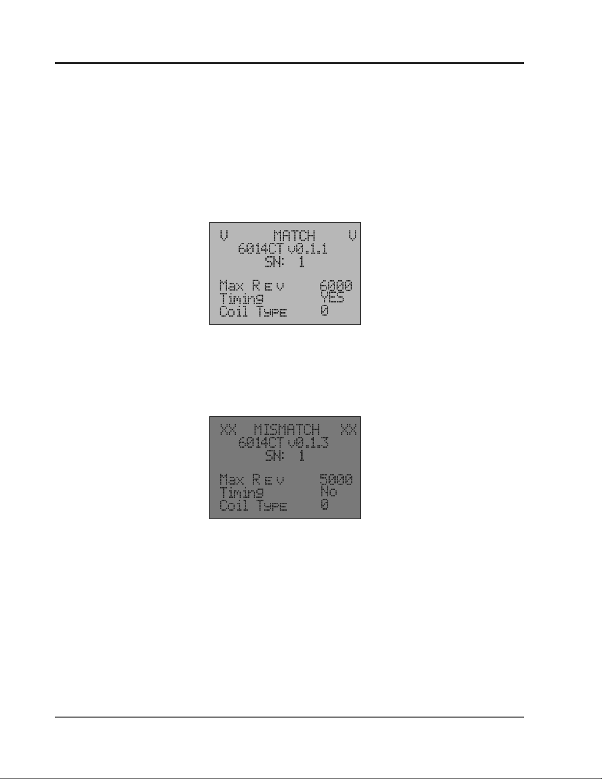
An example of a Match indication on the display (Figure 1):
Background is Green
Top line: “V MATCH V”
Second line: Part Number and software version
Third line: Serial Number
Actual readings from the unit are displayed
Figure 2 Display Match Screen
An example of Mismatch indication on the display (Figure 2):
Background is Red
Top of the screen shows “XX MISMATCH XX”
Actual readings from the unit are displayed
Figure 3 Display Mismatch Screen
Note: For the Test Tool to operate the ignition power must be ON.
M S D • • ( 9 1 5 ) 8 5 7 - 5 2 0 0 • F A X ( 9 1 5 ) 8 5 7 - 3 3 4 4W W W . M S D P E R F O R M A N C E . C O M
Page 3

IN S TAL L ATI O N IN S T RU C T IO N S 3
MASTER UNIT REPLACEMENT
Note: Before replacing the Master unit, the intended unit needs to be programmed by MSD View
according to the requirements of the sanctioning body. The checkboxes associated with the
regulated parameters must be checked in the REGULATED tab.
1. Connect the MSD Tech Tool to the CAN bus port.
2. Press “down” once for the readings of the Master unit to be displayed
3. Press “right” to replace the Master unit
4. Press “up” for two seconds to confirm the Master replacement
5. A message “MASTER REPLACED SUCCESSFULLY” will be displayed
OPERATION WITH THE 7730 POWER GRID
Connect the MSD Tech Tool to the Power Grid CAN bus. Scroll right to read the different
parameters, Modules connected, or to change the display settings.
The MSD Tech Tool displays the part numbers, serial Numbers and software version number of all
units connected on the CAN bus.
Ÿ If the Power Grid PN 7730 was operating for over an hour without the ARC Module the
background light will be green and the TC Timeout will read 0.
Ÿ If the ARC module was recently connected, the TC Timeout will read 60 minutes and the
background light will be red.
Ÿ While the 7730 operates with the engine running without the ARC module, the Timeout timer
within the 7730 will decrement in 3 minutes intervals. The background light of the MSD Race
Ignition Test Tool will be orange during values between 3 to 57 minutes.
7730 Harness
(ONLY CAN BUS
PIGTAIL IS SHOWN)
CAN BUS
RESISTOR
REQUIRED
CAN BUS HUB
PN 7740
Figure 4 PN89973 System
M S D • • ( 9 1 5 ) 8 5 7 - 5 2 0 0 • F A X ( 9 1 5 ) 8 5 7 - 3 3 4 4W W W . M S D P E R F O R M A N C E . C O M
Page 4

®
TECH NOTES
Service
In case of malfunction, this MSD component will be repaired free of charge according to the terms of the
warranty. When returning MSD components for warranty service, Proof of Purchase must be supplied for
verication. After the warranty period has expired, repair service is based on a minimum and maximum fee.
All returns must have a Return Material Authorization (RMA) number issued to them before being
returned. To obtain an RMA number please contact MSD Customer Service at 1 (888) MSD-7859 or visit
our website at www.msdperformance.com/rma to automatically obtain a number and shipping
information.
When returning the unit for repair, leave all wires at the length in which you have them installed. Be sure to
include a detailed account of any problems experienced, and what components and accessories are
installed on the vehicle. The repaired unit will be returned as soon as possible using Ground shipping
methods (ground shipping is covered by warranty). For more information, call MSD at (915) 855-7123.
MSD technicians are available from 7:00 a.m. to 5:00 p.m. Monday - Friday (mountain time).
Limited Warranty
MSD warrants this product to be free from defects in material and workmanship under its intended
normal use*, when properly installed and purchased from an authorized MSD dealer, for a period of one year from
the date of the original purchase. This warranty is void for any products purchased through auction websites. If
found to be defective as mentioned above, it will be repaired or replaced at the option of MSD. Any item that is
covered under this warranty will be returned free of charge using Ground shipping methods.
This shall constitute the sole remedy of the purchaser and the sole liability of MSD. To the extent permitted by law,
the foregoing is exclusive and in lieu of all other warranties or representation whether expressed or implied,
including any implied warranty of merchantability or tness. In no event shall MSD or its suppliers be liable for
special or consequential damages.
*Intended normal use means that this item is being used as was originally intended and for the original application
as sold by MSD. Any modications to this item or if it is used on an application other than what MSD markets the
product, the warranty will be void. It is the sole responsibility of the customer to determine that this item will work
for the application they are intending. MSD will accept no liability for custom applications.
M S D • • ( 9 1 5 ) 8 5 7 - 5 2 0 0 • F A X ( 9 1 5 ) 8 5 7 - 3 3 4 4W W W . M S D P E R F O R M A N C E . C O M
2017 MSD LLC
FRM34449 Created 01/17
Printed in U.S.A
 Loading...