

Page 1
Multi-Channel MSD Ignition Tester
PN 8996
These instructions detail how to use the Multi-Channel tester with an MSD 6, 7, 8, 10, Digital 7 Series Ignition
Control or Multi-function Controllers. If you need to test an MSD DIS Ignition, see pages 5 and 6.
WARNING: Do not connect directly to the coil or this unit will be damaged.
PARTS INCLUDED:
1 - Digital Ignition Tester
1 - Spark Tester
PROGRAMMING
PROGRAMS
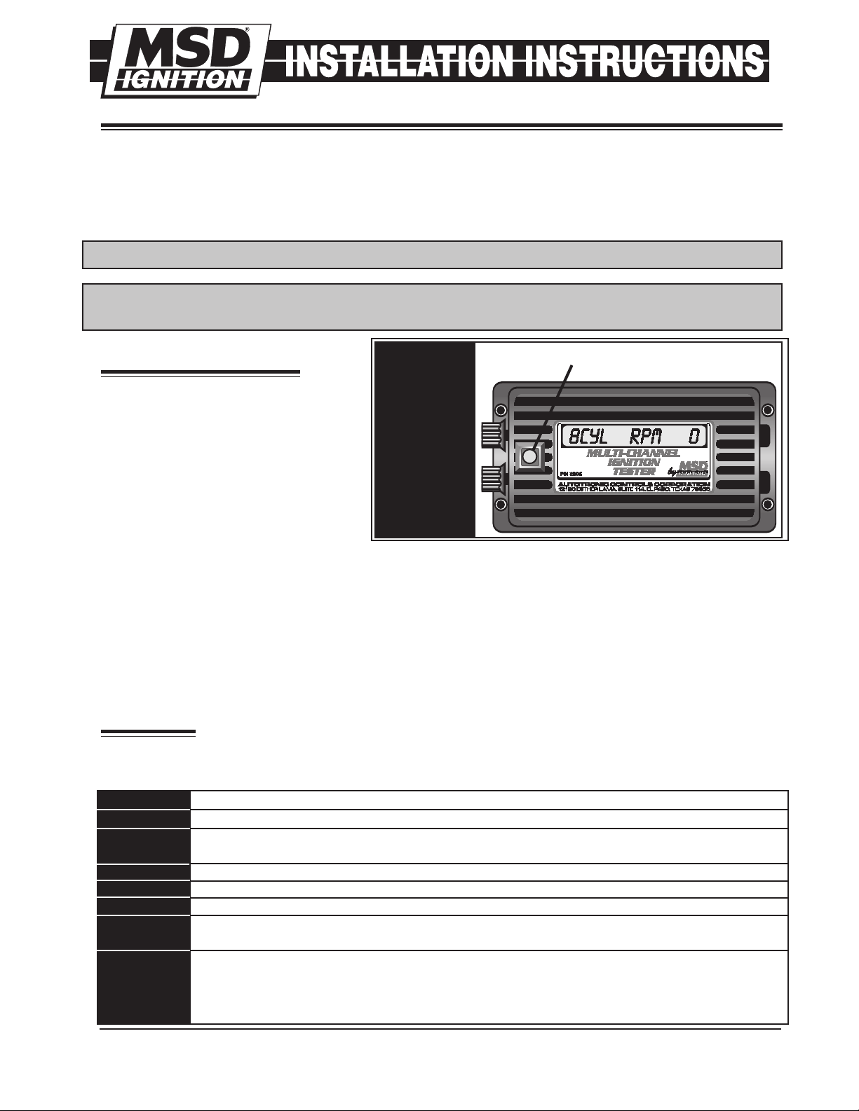
The MSD Multi-Channel Ignition Tester
has the ability to test several different
combinations of ignition setups. By
pushing the Red button on the face
of the unit different programs can be
selected. Figure 1 shows the different
applications.
When you first connect power to the
Tester, the LED will display the name
and Part Number. You can bypass this
information by pushing the Red button.
The Tester automatically defaults to the program for an 8-cylinder, single trigger ignition system. To select
a different program just press the Red Select button until the program you need is displayed.
Note: If you have an MSD DIS Ignition Control, two test harnesses are offered to make testing each
channel of the ignition easier. The DIS-4 Test Harness is PN 89964, the DIS-2 is PN 89962. These
Harnesses will allow you to test the ignition and coils without having to splice into any wires. Figure
9 shows the harness.
8 Cylinder
8 Cyl-DIS
6 Cylinder
6 Cyl-DIS
6 Cyl-Odd
4 Cylinder
4 Cyl-DIS
Figure 1 Ignition Tester Programs.
PROGRAM SELECTION
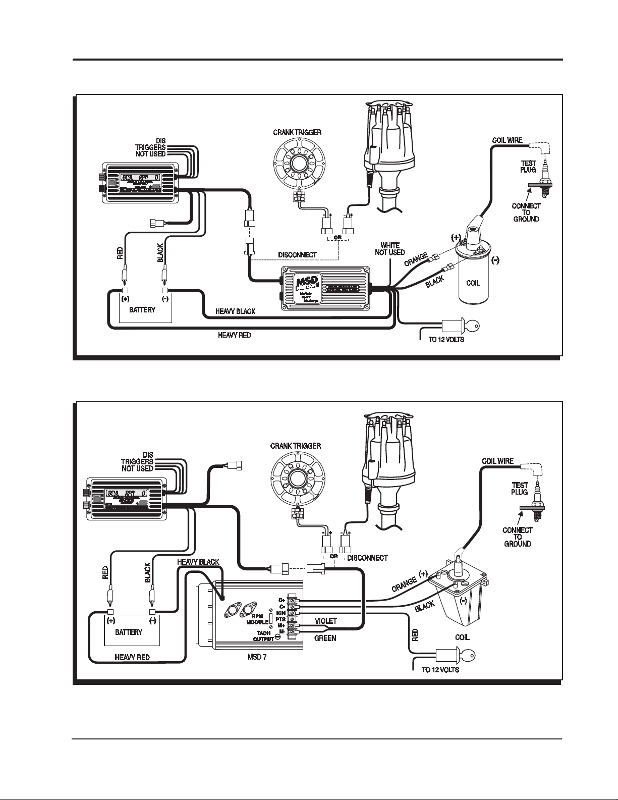
WIRING
The Digital Tester has several wires with boots and alligator clips on each one. The wires with White
boots are all trigger wires. Note: All of the wires are only used when testing a DIS-4 Ignition Control.
Red: Connect to 12 volts.
Black: Connect to a good ground source.
White: This is the trigger wire used to test the points/amplifier (white wire trigger) circuit of an
MSD Ignition. When testing DIS Ignitions, this is the Channel 1 trigger.
Green: Channel 2 for a DIS Ignition.
Yellow: Channel 3 for a DIS Ignition.
Violet: Channel 4 for a DIS Ignition.
Green/Violet:
directly into the MSD’s magnetic pickup connector. Violet is mag + and Green is mag -.
Lt. Blue/
Lt. Green:
M S D I G N I T I O N • ww w. msd ig ni tio n. co m • ( 9 15 ) 8 57 -5 20 0 • FA X (9 15) 85 7 -3 34 4
This 2-Pin connector is for testing the magnetic input circuit for MSD Ignitions. It plugs
This is a 2-pin connector for testing the cam sync pickup circuit of an MSD Programmable
Ignition or Multi-Function Controller. It plugs directly into the MSD Digital 7 Programmable
Ignition's cam pickup connector. Lt. Blue is cam (+) and Lt. Green is cam (-). The CPC
Ignition is supplied with a harness adapter.
Page 2

2 INSTALLATION INSTRUCTIONS
CAM SYNC
PICKUP OUTPUT
NOT USED
RPM ADjUSTMENT
The MSD Digital Tester has two rpm adjustments; Coarse and Fine:
Coarse Adjustment: When this knob is turned clockwise the rpm will
increase in 100 rpm increments. This allows a large spread of rpm to
be covered in a short period of time.
Fine Adjustment: When this knob is turned clockwise the rpm will
increase in 1 rpm increments for precise adjustments.
Figure 2 Adjusting the Tester’s RPM.
INSTALLATION & USE
1. Be sure the ignition is Off.
2. Remove the coil wire from the distributor cap and install the MSD Test Plug. Connect the Plug to
a ground source. Make sure the ground source is paint and corrosion free.
WARNING: A spark is going to jump across the tester’s gap. Make sure there are no fuel sources
or wiring near the tester.
4. Attach the Tester’s Red wire to a 12 volt source such as the positive battery terminal.
5. Connect the Black wire to ground.
6. Connect the trigger wire(s) to fit your application. This will be the wire(s) with the White alligator clips
or the 2-pin connector for magnetic pickups. See the following wiring diagrams in pages 2 - 4 for your
application. Note: The 2-pin Mag-pickup, Violet/Green connector will never be used with the other
trigger wires.
7. Make sure both the coarse and the fine adjustments on the tester are turned to the full counter
clockwise position (zero).
8. Turn the ignition switch On and press the red button of the Tester until your appropriate engine
combination is selected.
9. Increase the Coarse adjustment until you reach the desired rpm. Note that the test plug will be
firing. The fine adjustment can be used to get the exact rpm you desire.
Figure 3 Testing an MSD Triggered with Points or an Amplifier.
M S D I G N I T I O N • ww w. msd ig ni tio n. co m • ( 9 15 ) 8 57 -5 20 0 • FA X ( 915 ) 8 5 7- 33 44
Page 3
INSTALLATION INSTRUCTIONS 3
CAM SYNC PICKUP
OUTPUT NOT USED
CAM SYNC
PICKUP OUTPUT
NOT USED
Figure 4 Testing an MSD 6 Series Through the Magnetic Pickup.
Figure 5 Testing an MSD 7 Series Through the Magnetic Pickup.
M S D I G N I T I O N • ww w. msd ig ni tio n. co m • ( 9 15 ) 8 57 -5 20 0 • FA X ( 915 ) 8 5 7- 33 44
Page 4

4 INSTALLATION INSTRUCTIONS
CAM SYNC
PICKUP OUTPUT
NOT USED
DIS
TRIGGERS
NOT USED
Figure 6 Testing an MSD with Timing Accessory.
Figure 7 Testing an MSD Programmable 7 Series Inition.
M S D I G N I T I O N • ww w. msd ig ni tio n. co m • ( 9 15 ) 8 57 -5 20 0 • FA X ( 915 ) 8 5 7- 33 44
Page 5

INSTALLATION INSTRUCTIONS 5
CAM SYNC
PICKUP OUTPUT
NOT USED
CAM SYNC
PICKUP
OUTPUT
NOT USED
TESTING DIS IGNITIONS
WARNING: Do not connect directly to the coils or this unit will be damaged.
CAUTION: Do not connect more than one channel of the tester unless each spark plug wire is
removed from the spark plug in the cylinders and placed close to ground. If left
connected to the plugs, a spark will occur and could ignite any fuel in the cylinder
resulting in a backfire through the intake.
NOTE: It may be necessary to jump a 12 volt
source to the tester and DIS 2 input. Some
vehicles do not supply 12 volts to the coils
unless the engine is spinning.
Figure 8 Testing an MSD DIS-2 Ignition Control without PN 89962 Harness.
NOTE: It may be necessary to jump a 12
volt source to the tester and DIS-4
input. Some vehicles do not supply
12 volts to the coils unless the
engine is spinning.
Figure 9 Testing an MSD DIS-4 Ignition Control using the PN 89964 Test Harness.
M S D I G N I T I O N • ww w. msd ig ni tio n. co m • ( 9 15 ) 8 57 -5 20 0 • FA X ( 915 ) 8 5 7- 33 44
Page 6

6 INSTALLATION INSTRUCTIONS
TIPS & TROUBLESHOOTING:
No spark after Tester is connected:
• Make sure the DIS Brown wire is NOT grounded.
• Check for 12 volts on the Tester's Red wire.
• Inspect the wiring of the tester. Make sure you have a good ground and 12 volt source.
• Check to make sure you have the correct testing program for your application.
• When testing a DIS system, if one coil doesn’t spark, check the wiring and swap the trigger
wire with a different one and test again. If the same coil still does not spark, the coil is at fault.
TECH NOTES
_________________________________________________________________________________________________________________________
_________________________________________________________________________________________________________________________
_________________________________________________________________________________________________________________________
_________________________________________________________________________________________________________________________
_________________________________________________________________________________________________________________________
_________________________________________________________________________________________________________________________
_________________________________________________________________________________________________________________________
_________________________________________________________________________________________________________________________
_________________________________________________________________________________________________________________________
_________________________________________________________________________________________________________________________
_________________________________________________________________________________________________________________________
_________________________________________________________________________________________________________________________
_________________________________________________________________________________________________________________________
_________________________________________________________________________________________________________________________
_________________________________________________________________________________________________________________________
_________________________________________________________________________________________________________________________
_________________________________________________________________________________________________________________________
_________________________________________________________________________________________________________________________
_________________________________________________________________________________________________________________________
_________________________________________________________________________________________________________________________
_________________________________________________________________________________________________________________________
_________________________________________________________________________________________________________________________
_________________________________________________________________________________________________________________________
_________________________________________________________________________________________________________________________
_________________________________________________________________________________________________________________________
_________________________________________________________________________________________________________________________
_________________________________________________________________________________________________________________________
_________________________________________________________________________________________________________________________
_________________________________________________________________________________________________________________________
_________________________________________________________________________________________________________________________
M S D I G N I T I O N • ww w. msd ig ni tio n. co m • ( 9 15 ) 8 57 -5 20 0 • FA X ( 915 ) 8 5 7- 33 44
Page 7

INSTALLATION INSTRUCTIONS 7
TECH NOTES
_________________________________________________________________________________________________________________________
_________________________________________________________________________________________________________________________
_________________________________________________________________________________________________________________________
_________________________________________________________________________________________________________________________
_________________________________________________________________________________________________________________________
_________________________________________________________________________________________________________________________
_________________________________________________________________________________________________________________________
_________________________________________________________________________________________________________________________
_________________________________________________________________________________________________________________________
_________________________________________________________________________________________________________________________
_________________________________________________________________________________________________________________________
_________________________________________________________________________________________________________________________
_________________________________________________________________________________________________________________________
_________________________________________________________________________________________________________________________
_________________________________________________________________________________________________________________________
_________________________________________________________________________________________________________________________
_________________________________________________________________________________________________________________________
_________________________________________________________________________________________________________________________
_________________________________________________________________________________________________________________________
_________________________________________________________________________________________________________________________
_________________________________________________________________________________________________________________________
_________________________________________________________________________________________________________________________
_________________________________________________________________________________________________________________________
_________________________________________________________________________________________________________________________
_________________________________________________________________________________________________________________________
_________________________________________________________________________________________________________________________
_________________________________________________________________________________________________________________________
_________________________________________________________________________________________________________________________
_________________________________________________________________________________________________________________________
_________________________________________________________________________________________________________________________
_________________________________________________________________________________________________________________________
_________________________________________________________________________________________________________________________
_________________________________________________________________________________________________________________________
_________________________________________________________________________________________________________________________
_________________________________________________________________________________________________________________________
_________________________________________________________________________________________________________________________
_________________________________________________________________________________________________________________________
_________________________________________________________________________________________________________________________
M S D I G N I T I O N • ww w. msd ig ni tio n. co m • ( 9 15 ) 8 57 -5 20 0 • FA X ( 915 ) 8 5 7- 33 44
Page 8

TECH NOTES
_________________________________________________________________________________________________________________________
_________________________________________________________________________________________________________________________
_________________________________________________________________________________________________________________________
_________________________________________________________________________________________________________________________
_________________________________________________________________________________________________________________________
_________________________________________________________________________________________________________________________
_________________________________________________________________________________________________________________________
_________________________________________________________________________________________________________________________
_________________________________________________________________________________________________________________________
_________________________________________________________________________________________________________________________
_________________________________________________________________________________________________________________________
_________________________________________________________________________________________________________________________
_________________________________________________________________________________________________________________________
_________________________________________________________________________________________________________________________
_________________________________________________________________________________________________________________________
_________________________________________________________________________________________________________________________
_________________________________________________________________________________________________________________________
Service
In case of malfunction, this MSD component will be repaired free of charge according to the terms of the warranty.
When returning MSD components for warranty service, Proof of Purchase must be supplied for verification. After
the warranty period has expired, repair service is based on a minimum and maximum fee.
All returns must have a Return Material Authorization (RMA) number issued to them before
being returned. To obtain an RMA number please contact MSD Customer Service at 1 (888) MSD-7859 or
visit our website at www.msdignition.com/rma to automatically obtain a number and shipping information.
When returning the unit for repair, leave all wires at the length in which you have them installed. Be sure to include
a detailed account of any problems experienced, and what components and accessories are installed on the vehicle.
The repaired unit will be returned as soon as possible using Ground shipping methods (ground shipping is covered
by warranty). For more information, call MSD Ignition at (915) 855-7123. MSD technicians are available from 7:00
a.m. to 6:00 p.m. Monday - Friday (mountain time).
Limited Warranty
M
SD IGNITION warrants this product to be free from defects in material and workmanship under its intended normal
use*, when properly installed and purchased from an authorized MSD dealer, for a period of one year from the date
of the original purchase. This warranty is void for any products purchased through auction websites. If found to be
defective as mentioned above, it will be repaired or replaced at the option of MSD Ignition. Any item that is covered
under this warranty will be returned free of charge using Ground shipping methods.
This shall constitute the sole remedy of the purchaser and the sole liability of MSD Ignition. To the extent permitted
by law, the foregoing is exclusive and in lieu of all other warranties or representation whether expressed or implied,
including any implied warranty of merchantability or fitness. In no event shall MSD Ignition or its suppliers be liable
for special or consequential damages.
*Intended normal use means that this item is being used as was originally intended and for the original application
as sold by MSD Ignition. Any modifications to this item or if it is used on an application other than what MSD Ignition
markets the product, the warranty will be void. It is the sole responsibility of the customer to determine that this item
will work for the application they are intending. MSD Ignition will accept no liability for custom applications.
M S D I G N I T I O N • ww w. msd ig ni tio n. co m • ( 9 15 ) 8 57 -5 20 0 • FA X ( 915 ) 8 5 7- 33 44
© 2007 Autotronic Controls Corporation
FRM27925 Revised 05/07 Printed in U.S.A.
 Loading...