

Page 1
3-Stage Retard
PN 8970
IMPORTANT: Read the instructions before attempting the installation.
Parts Included:
1 - 3-Stage Retard Control 4 - Mounting Screws
4 - Mounting Grommets 6 - Retard Modules, 2°, 3°, 4°, 3-Zero°
WARNING: During installation disconnect the battery cables. When disconnecting the battery,
always remove the negative cable first and connect it last.
Note: The 3-Stage Retard Control must be used with an MSD Ignition Control.
Note: When the Three Stage Retard Control is installed the ignition timing will retard approximately
4° from its original setting. After installation, the timing should be checked and adjusted
as necessary.
OPERATION
The 3-Stage Retard Control can retard the timing three different times and each with an individual
amount. The three amounts are cumulative and the maximum amount of retard is 25°. Each retard
stage is activated when its corresponding activation wire is removed from ground and the retard will
remain activated until the wire is grounded again.
There is also a Start Retard circuit that
will retard the timing 10° or 25° during
cranking to ease starting on engines with
locked-out timing or crank triggers.
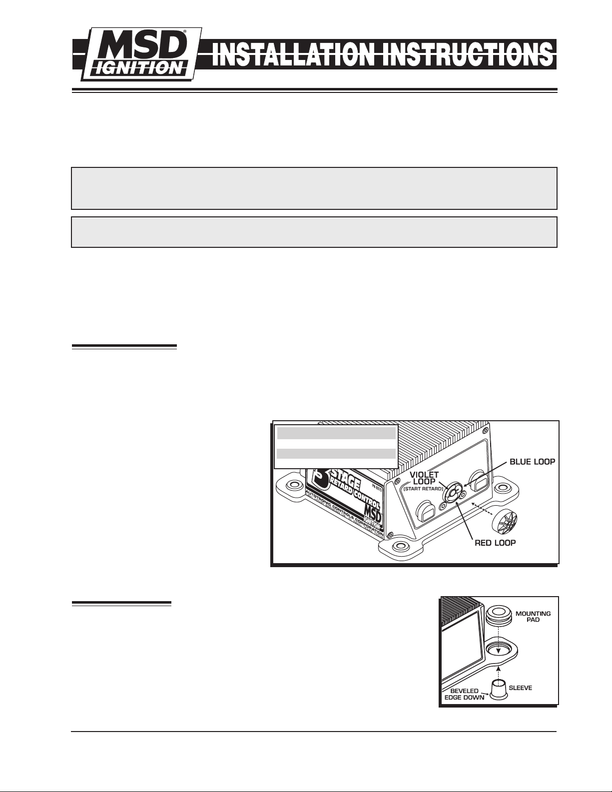
CYLINDER SELECT
T h e 3 - S t a ge Ret a r d C o n t r ol is
programmed at the factory for 8-cylinder
engines. It can easily be modified for use
on 4 and 6-cylinder engines. The number
of cylinders is selected by cutting the
Cylinder Select Loops as shown in
Figure 1.
CYLINDERS CUT LOOPS
8 NONE
6 RED
4 RED AND BLUE
Figure 1 Selecting the Number of Cylinders.
MOUNTING
The 3-Stage Retard Control can be mounted under the hood but should
be away from direct engine heat sources. Make sure that the wiring
reaches their connections. Before mounting the control, install the
supplied rubber grommets into the end panels. Then install the sleeve
with the beveled edge facing down (Figure 2).
Use the Control as a template and mark the mounting holes. Use an
1/8” bit to drill the mounting holes.
M S D I G N I T I O N • w w w . ms di g ni ti on. co m • ( 9 15 ) 8 5 7 -52 00 • F A X ( 91 5) 8 5 7-3 3 4 4
Figure 2 Installing the
Vibration Mounts.
Page 2
2 INSTALLATION INSTRUCTIONS
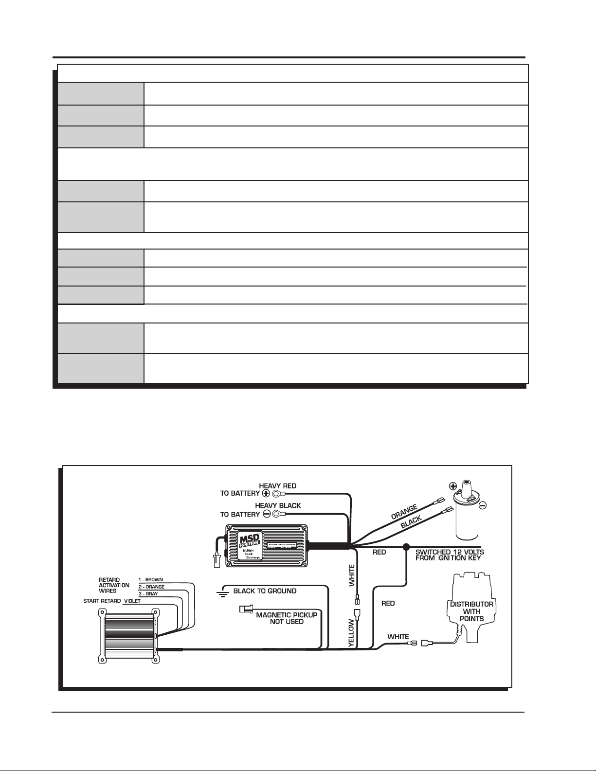
WIRING
RED
BLACK
YELLOW
This is the On/Off wire. Connects to switched 12 volts.
Connects to Ground.
Trigger output. Connects to the MSD Ignition's White Wire.
TRIGGER INPUTS
There are two input trigger circuits. The wires will never be connected at the same time.
WHITE
GREEN/VIOLET
2-Pin Connector
Connects to points or the amplifier trigger wire.
Connects to the magnetic pickup of the distributor or crank trigger. Green is
negative, Violet is positive.
RETARD CONTROL WIRES
BROWN
ORANGE
GRAY
Retard 1, Activated when removed from ground.
Retard 2, Activated when removed from ground.
Retard 3, Activated when removed from ground.
START RETARD WIRES
VIOLET
This wire activates the start retard. When 12 volts are supplied, the timing is
retarded during cranking.
VIOLET LOOP
This programs the start retard for either 10° or 25° of retard. The unit is
set for 10° at the factory and this loop must be cut to obtain 25°.
The Retard Control wires activate the corresponding retard stage. The retard amount is activated when its
wire is removed from ground. If you do not plan on using each stage, the corresponding wire must
be grounded or a Zero degree module must be installed.
When more than one are activated, the retard is the sum of the modules (6°+4°+8°=18°). The
maximum retard is 25°.
Figure 3 Wiring an MSD 6 Series Ignition with Points/Amplifier.
M S D I G N I T I O N • w w w . ms di g ni ti on. co m • ( 9 15 ) 8 5 7 -52 00 • F A X ( 91 5) 8 5 7-3 3 4 4
Page 3
INSTALLATION INSTRUCTIONS 3
Figure 4 Wiring an MSD 6 Series Ignition with a Mag Pickup.
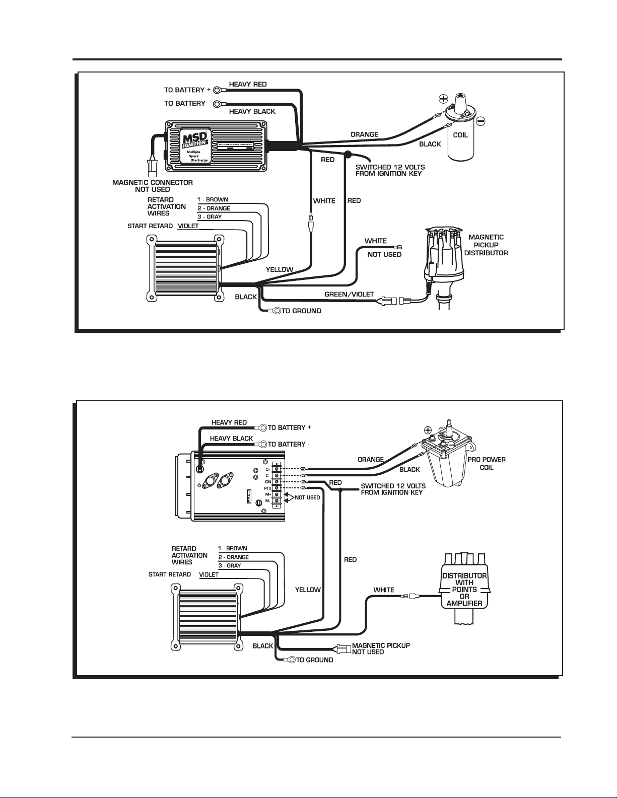
Figure 5 Wiring an MSD 7 Series Ignition with Points/Amplifier.
M S D I G N I T I O N • w w w . ms di g ni ti on. co m • ( 9 15 ) 8 5 7 -52 00 • F A X ( 91 5) 8 5 7-3 3 4 4
Page 4

4 INSTALLATION INSTRUCTIONS
Figure 6 Wiring an MSD 7 Series Ignition with a Mag Pickup.
Figure 7 Wiring a Digital 6-Plus or 7-Plus Ignition with a Mag Pickup.
M S D I G N I T I O N • w w w . ms di g ni ti on. co m • ( 9 15 ) 8 5 7 -52 00 • F A X ( 91 5) 8 5 7-3 3 4 4
Page 5

INSTALLATION INSTRUCTIONS 5
Figure 8 Wiring to an MSD 8 with a Mag Pickup.
CONNECTION
Figure 9 Wiring an MSD 10 PLUS with a Mag Pickup.
M S D I G N I T I O N • w w w . ms di g ni ti on. co m • ( 9 15 ) 8 5 7 -52 00 • F A X ( 91 5) 8 5 7-3 3 4 4
Page 6

6 INSTALLATION INSTRUCTIONS
Figure 10 Wiring a Complete Retard System.
Figure 11 Activation with an RPM Activated Switch.
M S D I G N I T I O N • w w w . ms di g ni ti on. co m • ( 9 15 ) 8 5 7 -52 00 • F A X ( 91 5) 8 5 7-3 3 4 4
Page 7

INSTALLATION INSTRUCTIONS 7
START RETARD
The Start Retard function is set up at the factory to retard the timing 10° during cranking. It can
be modified to retard 25° by cutting the Violet wire loop (Figure 12). The timing will be retarded
from the set mechanical amount of the distributor or crank trigger position.
The Violet wire is responsible for activating the Start Retard circuit. When activated, the Start
Retard function will retard the timing 10° or 25° while the engine is cranking. There are two
ways to connect this circuit:
A. Constant 12 Volts
In this setup the Violet wire is connected to a switched 12 volt source. Whenever the ignition is
turned On, 12 volts is applied and the retard function is activated. The retard will be deactivated
when the engine reaches approximately 1,300 rpm and will not occur again until the ignition
is turned Off (or drops below 400 rpm).
B. Cranking Only:
In this setup, the timing is retarded only when the engine is cranking. Connect the Violet wire
directly to the starter solenoid. When the key is turned to the Crank position, 12 volts is applied
to the Violet wire, activating the retard. When the key is released, 12 volts is removed and the
timing returns to your run timing.
Note: The Start Retard circuit overides the three retard stages.
Figure 12 Wiring the Start Retard Function.
M S D I G N I T I O N • w w w . ms di g ni ti on. co m • ( 9 15 ) 8 5 7 -52 00 • F A X ( 91 5) 8 5 7-3 3 4 4
Page 8

TECH NOTES
_________________________________________________________________________________________________________________________
_________________________________________________________________________________________________________________________
_________________________________________________________________________________________________________________________
_________________________________________________________________________________________________________________________
_________________________________________________________________________________________________________________________
_________________________________________________________________________________________________________________________
_________________________________________________________________________________________________________________________
_________________________________________________________________________________________________________________________
_________________________________________________________________________________________________________________________
_________________________________________________________________________________________________________________________
_________________________________________________________________________________________________________________________
_________________________________________________________________________________________________________________________
_________________________________________________________________________________________________________________________
_________________________________________________________________________________________________________________________
_________________________________________________________________________________________________________________________
_________________________________________________________________________________________________________________________
Service
In case of malfunction, this MSD component will be repaired free of charge according to the terms of the warranty.
When returning MSD components for warranty service, Proof of Purchase must be supplied for verification. After
the warranty period has expired, repair service is based on a minimum and maximum fee.
All returns must have a Return Material Authorization (RMA) number issued to them before
being returned. To obtain an RMA number please contact MSD Customer Service at 1 (888) MSD-7859 or
visit our website at www.msdignition.com/rma to automatically obtain a number and shipping information.
When returning the unit for repair, leave all wires at the length in which you have them installed. Be sure to include
a detailed account of any problems experienced, and what components and accessories are installed on the vehicle.
The repaired unit will be returned as soon as possible using Ground shipping methods (ground shipping is covered
by warranty). For more information, call MSD Ignition at (915) 855-7123. MSD technicians are available from 7:00
a.m. to 6:00 p.m. Monday - Friday (mountain time).
Limited Warranty
M
SD IGNITION warrants this product to be free from defects in material and workmanship under its intended normal
use*, when properly installed and purchased from an authorized MSD dealer, for a period of one year from the date
of the original purchase. This warranty is void for any products purchased through auction websites. If found to be
defective as mentioned above, it will be repaired or replaced at the option of MSD Ignition. Any item that is covered
under this warranty will be returned free of charge using Ground shipping methods.
This shall constitute the sole remedy of the purchaser and the sole liability of MSD Ignition. To the extent permitted
by law, the foregoing is exclusive and in lieu of all other warranties or representation whether expressed or implied,
including any implied warranty of merchantability or fitness. In no event shall MSD Ignition or its suppliers be liable
for special or consequential damages.
*Intended normal use means that this item is being used as was originally intended and for the original application
as sold by MSD Ignition. Any modifications to this item or if it is used on an application other than what MSD Ignition
markets the product, the warranty will be void. It is the sole responsibility of the customer to determine that this item
will work for the application they are intending. MSD Ignition will accept no liability for custom applications.
M S D I G N I T I O N • w w w . ms di g ni ti on. co m • ( 9 15 ) 8 5 7 -52 00 • F A X ( 91 5) 8 5 7-3 3 4 4
© 2007 Autotronic Controls Corporation
FRM28617 Revised 05/07 Printed in U.S.A.
 Loading...