

Page 1
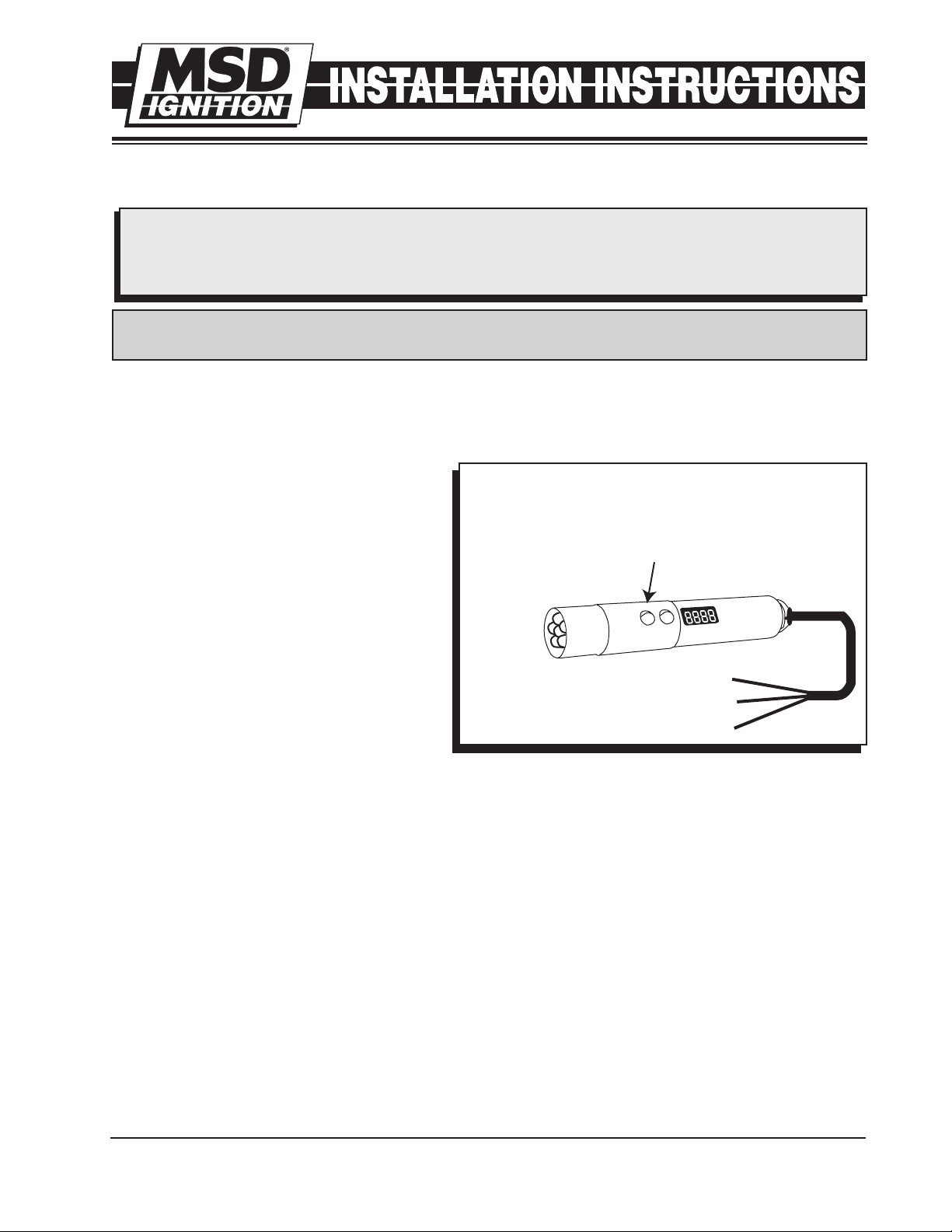
MSD Digital Shift Light
U
P
MODE
D
O
W
N
PROGRAMMING
BUTTONS
RED TO SWITCHED 12 VOLTS
GREEN TO TACH SIGNAL
BLACK TO GROUND
PROGRAMMING
CY - Cylinder Count
12, 10, 8, 6, 6 odd, 4, 2, 2 odd, 1
LuL - Light Intensity
Scale of 9-0 Bright to Dim
Use Up/Down
buttons to adjust
cylinders, intensity
and rpm points.
PN 89631
Parts Included:
1 - Shift Light
1 - Mounting Bracket
1 - GMR Pickup, PN 8918
WARNING: When installing the Shift Light disconnect the battery cables. When disconnecting,
always remove the negative cable first and install it last.
IMPORTANT: Do NOT connect to the coil (-) terminal. The supplied GMR pickup must be used
when installing the Digital Shift Light unless the rpm signal is coming from the tach
output of an MSD Ignition or aftermarket ECU. Damage to the DSL will occur if connected to a high voltage trigger source.
PROGRAMMING
By pressing the two buttons simultaneously, you get the Shift Light into the different
programming modes.
RPM: To adjust the rpm, press the two buttons until the rpm shows. Notice that all
of the numbers flash. Adjust the rpm then
push the two buttons again to move to the
next mode. The rpm can be set up to 16,000
rpm. Once you go over 9,900 rpm, the display will show 1,000 indicating 10,000 rpm
and higher.
2 - Washers
1 - Brass Screw
1 - Parts Bag
Cylinder Count: The display will read CY
and allow you to select between one to 12cylinder engines using the Up/Down buttons. On single cylinder two stroke or four
stroke applications that fire every revolution
(waste spark systems) the shift light should be programmed for two cylinder operation for correct operation.
Intensity: Control the intensity of the LED and read out. Hold the buttons until LuL displays. Use the
buttons to select from 9 (brightest) to 0 to turn off the shift light.
Self: Self mode will walk through all of the settings programmed into the light. It will first show the
rpm shift value for the shift light, the cylinder count and light intensity. Start the test mode by pushing either button once Self is displayed. To reset the Self mode, push either button when SELF is
displayed, or turn the power Off.
Each time the DSL is powered on, the LED will display the program values that are set.
INSTALLATION
The Shift Light installs easily with the GMR Pickup or through the tach output terminal of an MSD Ignition Control or aftermarket ECU. It will accept a trigger signal rated from 0-24 volt amplitude. Never
connect the Green Wire directly to the coil negative terminal.
If an ignition control or aftermarket ECU are not being used, the GMR pickup must be connected.
M S D I G N I T I O N • w w w . ms di g ni ti on. c o m • ( 9 1 5) 85 7 - 520 0 • F A X ( 9 1 5) 85 7 - 33 44
Figure 1 Digital Shift Light Wiring and Programming.
Page 2
2
MAGNETIC
CONNECTOR
NOT USED
TO BATTERY
WHITE
BLACK
ORANGE
WHITE
BLACK
ORANGE
RED
TO BATTERY
TRIGGER INPUT
RED
RED
SWITCHED
12 VOLT
GREEN
BLACK GROUND
U
P
MODE
D
O
W
N
COIL
OPTIONAL 2.2K RESISTOR
FOR NOISE FILTER
MAGNETIC
CONNECTOR
NOT USED
WHITE
BLACK
ORANGE
RED
RED
RED
SWITCHED
12 VOLT
GREEN
BLACK GROUND
U
P
MODE
D
O
W
N
RED
GREEN
OPTIONAL 2.2K RESISTOR
FOR NOISE FILTER
INSTALLATION INSTRUCTIONS
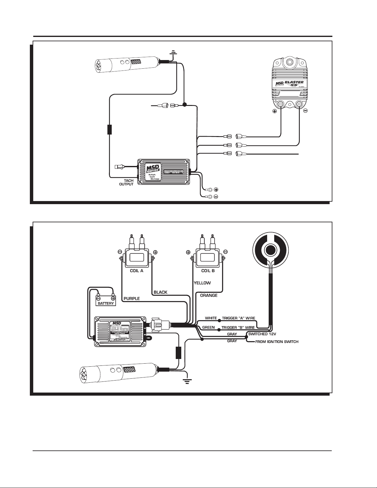
Note: If the rpm display
shows interference,
install the supplied
2.2K ohm resistor in-line on the
Green wire.
Note: If the rpm display
shows interference,
install the supplied
2.2K ohm resistor in-line on the
Green wire.
Figure 2 Installing with an MSD Ignition.
Figure 3 Installing with an MSD Motorcycle Ignition.
M S D I G N I T I O N • w w w . ms di g ni ti on. c o m • ( 9 1 5) 85 7 - 520 0 • F A X ( 9 1 5) 85 7 - 33 44
Page 3

I
BLACK GROUND
GMR PICKUP
RED
GREEN
SWITCHED
12 VOLT
SIGNAL
OUTPUT
GMR PICKUP
NOTE: The brass screw must be used for proper operation.
PRIMARY COIL (+) WIRE OR
DIESEL INJECTOR 12 VOLT WIRE
WASHER MUST BE ON TOP OF METAL TAB
METAL TAB
COIL
HARNESS
IGNITION
COIL
IGNITION
COIL
IGNITION
COIL
IGNITION
COIL
COIL (+)
12 VOLTS
COIL (-)
TRIGGER 4
COIL (-)
TRIGGER 3
COIL (-)
TRIGGER 2
COIL (-)
TRIGGER 1
GMR PICKUP
GREEN
SHIFT LIGHT
BLACK GROUND
U
P
MODE
D
OW
N
BLACK GROUND
RED
GREEN
SWITCHED
12 VOLT
SIGNAL
OUTPUT
GREEN
GMR PICKUP
NOTE: The brass screw must be used for proper operation.
PRIMARY COIL (+) WIRE OR
DIESEL INJECTOR 12 VOLT WIRE
WASHER MUST BE ON TOP OF METAL TAB
METAL TAB
GMR PICKUP
GMR PICKUP
COIL (-) 2
COIL (-) 1
COIL (+)
IGNITION 12 VOLTS
TRIGGER COIL 1
TRIGGER COIL 2
COIL HARNESS
POWERTRAIN CONTROL MODULE
BLACK GROUND
U
P
MODE
D
O
W
N
RED
PRIMARY COIL (+) WIRE
WASHER MUST BE ON TOP OF METAL TAB
METAL TAB
GMR PICKUP
NSTALLATION INSTRUCTIONS 3
GMR PICKUP INSTALLATION
The MSD GMR pickup can be used with inductive or capacitive ignition types to provide
an rpm signal of 30% duration when the ignition coil fires. Two washers are provided with
the pickup and must be installed in one of two
positions depending on the type of ignition
driving the coil. For late model applications, it
is recommended to have a wiring schematic
of the vehicle’s ignition system. On some
motorcycle and ATV applications, the stock
coils do not produce a long enough pulse. In these cases, loop the coil wire through the GMR
pickup twice (Figure 4).
Note: The shift light must
be programmed
for 1-cylinder operation.
Figure 4 Looping Coil Wire.
M S D I G N I T I O N • w w w . ms di g ni ti on. c o m • ( 9 1 5) 85 7 - 520 0 • F A X ( 9 1 5) 85 7 - 33 44
Figure 5 Installation on an Inductive Coil-Per-Cylinder Ignition System.
Figure 6 Installing to an Inductive Coil Pack.
Note: The shift light must
be programmed
for two (2) cylinder
operation.
Page 4

BLACK GROUND
RED
GREEN
SWITCHED
12 VOLT
SIGNAL
OUTPUT
GMR PICKUP
NOTE: The brass screw must be used for proper operation.
PRIMARY COIL (+) WIRE OR
DIESEL INJECTOR 12 VOLT WIRE
WASHER MUST BE ON TOP OF METAL TAB
METAL TAB
INJECTOR
POWER WIRE
GMR PICKUP
GREEN
SHIFT LIGHT
BLACK GROUND
U
P
MODE
D
O
W
N
INJECTOR
12 VOLT WIRE
TO GROUND
ON CYLINDER
HEAD
BLACK
RED
IGNITION
TM
CHASSIS
GROUND
GMR PICKUP
NOTE: The brass screw must be used for proper operation.
PRIMARY COIL (+) WIRE OR
DIESEL INJECTOR 12 VOLT WIRE
WASHER MUST BE ON TOP OF METAL TAB
METAL TAB
BLACK
GROUND
GMR PICKUP
RED
GREEN
SWITCHED
12 VOLT
GREEN
SHIFT LIGHT
BLACK GROUND
U
P
MODE
D
O
W
N
Figure 7 Wiring the Pro Mag 44 Electronic Points Box.
Note: The shift light must
be programmed for
1-cylinder operation.
Note: For 12 Amp Pro Mags, connect the
GMR Pickup to the Orange wire
leading to the kill switch.
In case of malfunction, this MSD component will be repaired free of charge according to the terms of the warranty. When returning MSD
components for service, Proof of Purchase must be supplied for warranty verification. After the warranty period has expired, repair service
is charged based on a minimum and maximum charge.
All returns must have a Return Material Authorization (RMA) number issued to them before being returned. To obtain an
RMA number please contact MSD Customer Service at 1 (888) MSD-7859 or visit our website at www.msdignition.com/rma to automatically
obtain a number and shipping information.
When returning the unit for repair, leave all wires at the length in which you have them installed. Be sure to include a detailed account of
any problems experienced, and what components and accessories are installed on the vehicle.
The repaired unit will be returned as soon as possible after receipt. (Ground shipping is covered by warranty). All units are returned regular
UPS unless otherwise noted. For more information, call MSD Ignition at (915) 855-7123. MSD technicians are available from 7:00 a.m. to
6:00 p.m. Monday - Friday (mountain time).
M S D I G N I T I O N • w w w . ms di g ni ti on. c o m • ( 9 1 5) 85 7 - 520 0 • F A X ( 9 1 5) 85 7 - 33 44
FRM29015 Revised 11/07 Printed in U.S.A.
Figure 8 Installation to a Diesel Injector.
© 2007 Autotronic Controls Corpor ation
Service
 Loading...