

Page 1
MSD GMR Pickup
PN 8918/PN 89181
Parts Included:
1 - Giant Magnetoresistive Pickup, PN 8918/PN 89181
2 - Washers
1 - Brass Screw
1 1 - Parts Bag
The MSD GMR pickup can be used with inductive or capacitive ignition types to provide an rpm signal of 30% duration when the ignition coil fires. Two washers are provided with the pickup and must
be installed in one of two positions depending on the type of ignition driving the coil.
Note: For late model applications, it is recommended to have a wiring schematic of the vehicle’s
ignition system.
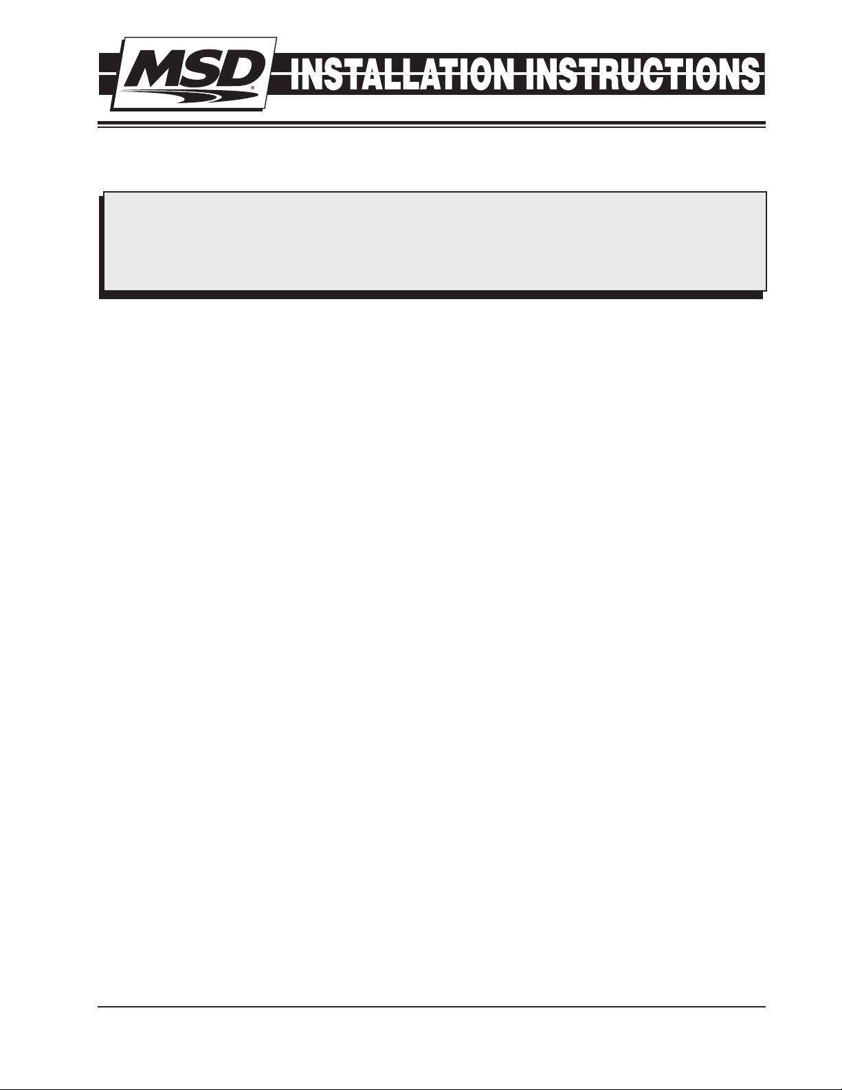
CAPACITIVE DISCHARGE IGNITIONS
For a CD Ignition such as an MSD, the two washers should be installed under the metal tab to provide a small air gap between the metal tab and the pickup sensor (Figure 1). Refer to note on Figure
2 for RPM Device programming.
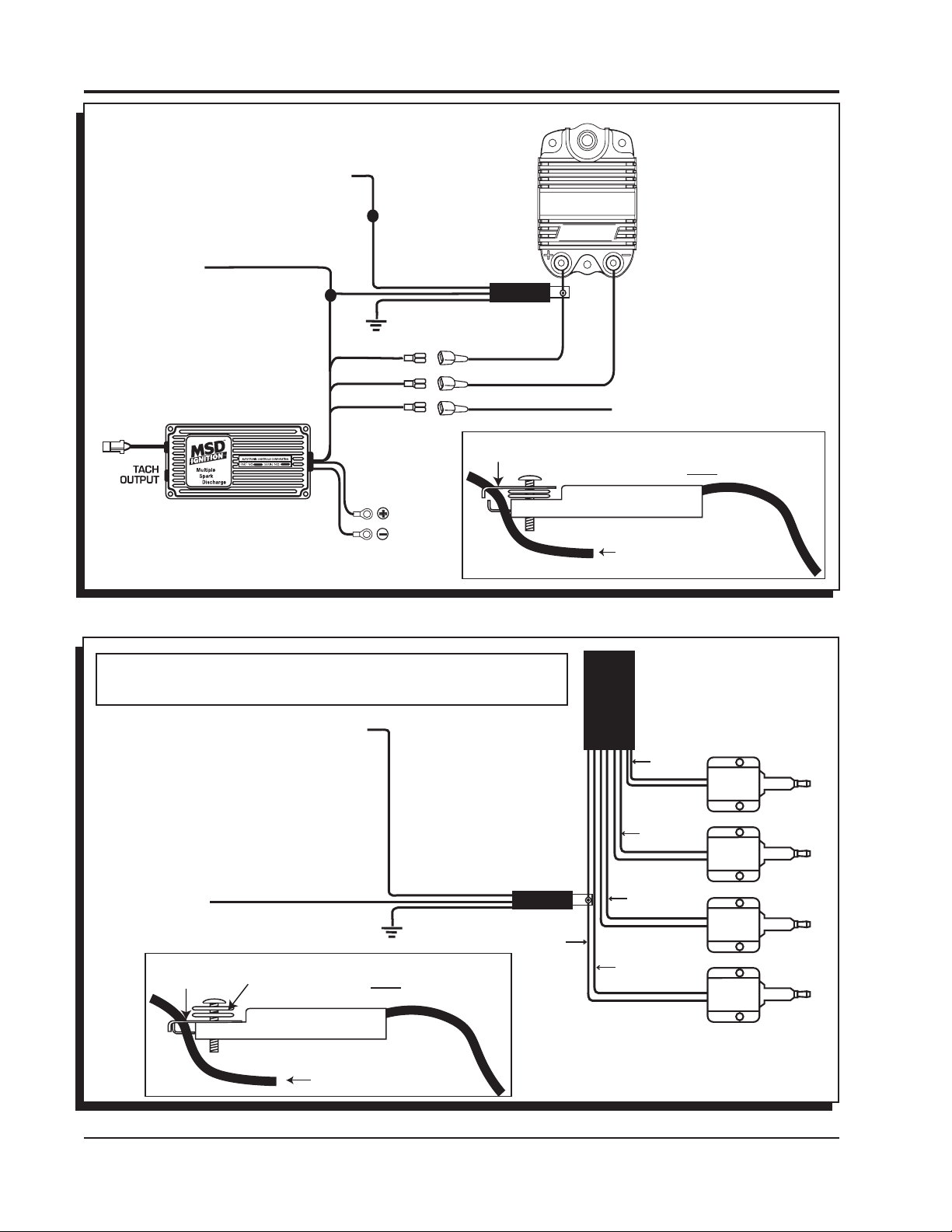
INDUCTIVE COIL PER CYLINDER IGNITION
For an inductive ignition (mostly stock applications) the metal tabs must make contact, therefore no washer is required. There should be no air gap between the metal tab and the pickup sensor (Figure 2). Refer
to note on Figure 3 for RPM Device programming.
DISTRIBUTORLESS COIL PACKS
On distributorless applications, the GMR pickup must be installed on the primary lead going to one
of the coils. If the pickup is installed on the main ignition +12v wire feeding more than one coil, the
pickup may not operate correctly at high speeds because of overlapping coil dwell current failing to
fall to zero current between coil operating cycles (Figure 3). Refer to note on Figure 3 for RPM Device
programming.
DIESEL INJECTOR
The GMR Pickup can easily be clipped to power fed wire of a Diesel Injector to provide a tach signal.
On a diesel, the washer must be installed under the screw head on top of the metal tab so there is
no air gap between the metal tab and the pickup sensor (Figure 4).
Note: If the GMR Pickup is attached directly to the individual injector the RPM device that is being
used must be programmed for single cylinder application. If the GMR Pickup is attached to
the main 12 volt feed to the injector harness, the RPM device must be programmed for 4, 6 or
8 cylinder depending on application.
M S D • W W W . M S D P E R F O R M A N C E . C O M • ( 9 1 5 ) 8 5 7 - 5 2 0 0 • F A X ( 9 1 5 ) 8 5 7 - 3 3 4 4
Page 2
2
BLACK GROUND
MAGNETIC
CONNECTOR
NOT USED
TO BATTERY
WHITE
BLACK
ORANGE
WHITE
BLACK
ORANGE
RED
TO BATTERY
BLACK
TRIGGER INPUT
GMR PICKUP
RED
RED
RED
GREEN
SWITCHED
12 VOLT
SIGNAL
OUTPUT
GREEN
CD IGNITION PRIMARY COIL (+) WIRE
(MSD - ORANGE)
BOTH WASHERS MUST BE UNDER METAL TAB
METAL TAB
GMR PICKUP
NOTE: The brass screw must be used for proper operation.
TO RPM
ACTIVATED DEVICE
INSTALLATION INSTRUCTIONS
Note: The device that
the green signal
output wire is attached must be
programmed for
4, 6 or 8 cylinder
depending on
application.
Figure 1 Installation with a Capacitive Discharge Ignition Control.
Note: The device that the green signal output wire is attached
must be programmed for single (1) cylinder operation.
TO RPM ACTIVATED
DEVICE
SWITCHED
12 VOLT
METAL TAB
RED
NOTE: The brass screw must be used for proper operation.
BOTH WASHERS MUST BE ON TOP OF METAL TAB
RED
GMR PICKUP
GMR PICKUP
Figure 2 Installation on an Inductive Distributorless Ignition System.
M S D • W W W . M S D P E R F O R M A N C E . C O M • ( 9 1 5 ) 8 5 7 - 5 2 0 0 • F A X ( 9 1 5 ) 8 5 7 - 3 3 4 4
GREEN
SIGNAL
OUTPUT
GREEN
BLACK GROUND
PRIMARY COIL (+) WIRE OR
DIESEL INJECTOR 12 VOLT WIRE
GMR PICKUP
COIL (+)
12 VOLTS
COIL
HARNESS
COIL (-)
TRIGGER 2
COIL (-)
TRIGGER 3
COIL (-)
TRIGGER 4
COIL (-)
TRIGGER 1
IGNITION
COIL
IGNITION
COIL
IGNITION
COIL
IGNITION
COIL
Page 3

I
NSTALLATION INSTRUCTIONS 3
POWERTRAIN CONTROL MODULE
TO RPM ACTIVATED
DEVICE
GREEN
Note: The device that the
green signal output wire
is attached must be programmed for four (4) cyl-
SIGNAL
COIL (- ) 2
COIL (- ) 1
COIL (+ )
OUTPUT
GREEN
inder operation.
COIL HARNESS
TRIGGER COIL 2
IGNITION 12 VOLTS
TRIGGER COIL 1
METAL TAB
Figure 3 Installation on a Distributorless Coil Pack.
Note: The device that the green
signal output wire is attached
must be programmed for single (1) cylinder operation.
GMR PICKUP
TO RPM ACTIVATED
DEVICE
RED
BLACK GROUND
NOTE: The brass screw must be used for proper operation.
BOTH WASHERS MUST BE ON TOP OF METAL TAB
GMR PICKUP
GMR PICKUP
PRIMARY COIL (+) WIRE OR
DIESEL INJECTOR 12 VOLT WIRE
GREEN
RED
SWITCHED
12 VOLT
SIGNAL
OUTPUT
GREEN
RED
SWITCHED
12 VOLT
INJECTOR
POWER WIRE
GMR PICKUP
BLACK GROUND
METAL TAB
RED
NOTE: The brass screw must be used for proper operation.
BOTH WASHERS MUST BE ON TOP OF METAL TAB
GMR PICKUP
PRIMARY COIL (+) WIRE OR
DIESEL INJECTOR 12 VOLT WIRE
Figure 4 Installation to a Diesel Injector.
M S D • W W W . M S D P E R F O R M A N C E . C O M • ( 9 1 5 ) 8 5 7 - 5 2 0 0 • F A X ( 9 1 5 ) 8 5 7 - 3 3 4 4
Page 4

CHASSIS
GROUND
TO RPM ACTIVATED DEVICE
SWITCHED
12 VOLT
METAL TAB
SIGNAL
OUTPUT
GREEN
RED
BLACK
GROUND
NOTE: The brass screw must be used for proper operation.
WASHER MUST BE ON TOP OF METAL TAB
GMR PICKUP
PRIMARY COIL (+) WIRE OR
DIESEL INJECTOR 12 VOLT WIRE
IGNITION
Figure 5 GMR to PN 8963 Shift Light on Pro Mag 44 Electronic Points Box.
METAL TAB
NOTE: The brass screw must be used for proper operation.
WASHER MUST BE ON TOP OF METAL TAB
GMR PICKUP
RED
TM
GMR PICKUP
GMR PICKUP
PRIMARY COIL (+) WIRE OR
DIESEL INJECTOR 12 VOLT WIRE
BLACK
TO GROUND
ON CYLINDER
HEAD
TO RPM
ACTIVATED DEVICE
GREEN
SIGNAL
OUTPUT
SWITCHED
GMR PICKUP
BLACK GROUND
12 VOLT
RED
Figure 6 Wiring the 12 Amp Pro Mag with GMR and PN 8963 Shift Light.
Service
In case of malfunction, this MSD component will be repaired free of charge according to the terms of the warranty. When
returning MSD components for warranty service, Proof of Purchase must be supplied for verification. After the warranty period
has expired, repair service is based on a minimum and maximum fee.
All returns must have a Return Material Authorization (RMA) number issued to them before
being returned. To obtain an RMA number please contact MSD Customer Service at 1 (888) MSD-7859 or visit
our website at www.msdperformance.com/rma to automatically obtain a number and shipping information.
When returning the unit for repair, leave all wires at the length in which you have them installed. Be sure to include a detailed
account of any problems experienced, and what components and accessories are installed on the vehicle. The repaired unit will
be returned as soon as possible using Ground shipping methods (ground shipping is covered by warranty). For more information,
call MSD at (915) 855-7123. MSD technicians are available from 7:00 a.m. to 5:00 p.m. Monday - Friday (mountain time).
M S D • W W W . M S D P E R F O R M A N C E . C O M • ( 9 1 5 ) 8 5 7 - 5 2 0 0 • F A X ( 9 1 5 ) 8 5 7 - 3 3 4 4
© 2012 Autotr onic Contro ls Corporati on
FRM29674 Revised 01/12 Printed in U.S.A.
 Loading...