

Page 1
MSD Cap and Rotor
for GM LT-1 Engines 1995-1997
PN 84811
ONLINE PRODUCT REGISTRATION: Register your MSD product online and you’ll be entered
in our monthly 8.5mm Super Conductor Spark Plug Wire give-away! Registering your product
will help if there is ever a warranty issue with your product and helps the MSD R&D team create
new products that you ask for! Go to www.msdperformance.com/registration.
Parts Included:
1 - Cap
1 - Rotor
1 - Isolator
2 - Rotor Screws
2 - Seals
IMPORTANT: Due to the number of applications and years that the LT-1 Cap and Rotor are used
on, it is highly recommended to have the Service Manual for your vehicle during this
installation.
DISASSEMBLY
1. Disconnect the negative battery cable.
2. Locate the radiator petcock and drain the coolant from the system.
3. Disconnect the MAF and IAC sensors. Remove the air intake ductwork and the MAF sensor.
4. Once the coolant is drained, remove the upper radiator hose from the thermostat housing.
5. Loosen the three bolts that secure the crankshaft pulley/hub assembly. Do not remove them
entirely at this time.
6. Remove the accessory drive belt by moving the spring loaded idler pulley. Use caution as this
pulley is spring loaded! The belt will slide off the pulley system and the idler pulley will settle
beyond its installed position.
7. Once the belt is removed, proceed with removing the pulley from the crankshaft hub by pulling
the three retaining bolts.
8. It may be necessary to remove the cooling fan. This is done by removing the four bolts and
disconnecting the wiring connection.
9. Disconnect the air pump power wires and remove the
air pump from its mounting brackets.
10. Disconnect the coolant temperature wiring sensor
located on the water pump.
11. Loosen the lower radiator hose clamp and the two heater
hose clamps at the water pump. Coolant will generally
still pour out of the hoses and water pump.
12. To remove the water pump, the power steering pump
may need to be removed. With a shorter extension, the
water pump bolt should be able to be accessed. There
are six water pump bolts. Once again, more coolant may
spill out.
13. At this point, you should be able to access the distributor
cap! Mark the location of each spark plug wire before
removing them.
14. Remove the vacuum lines (if equipped) and the distributor
4 - 3.5mm x 6mm Phillips Screws
1 - 8-32 x 1.125 Phillips Screw
1 - Clamp-Block
1 - Removal Tool
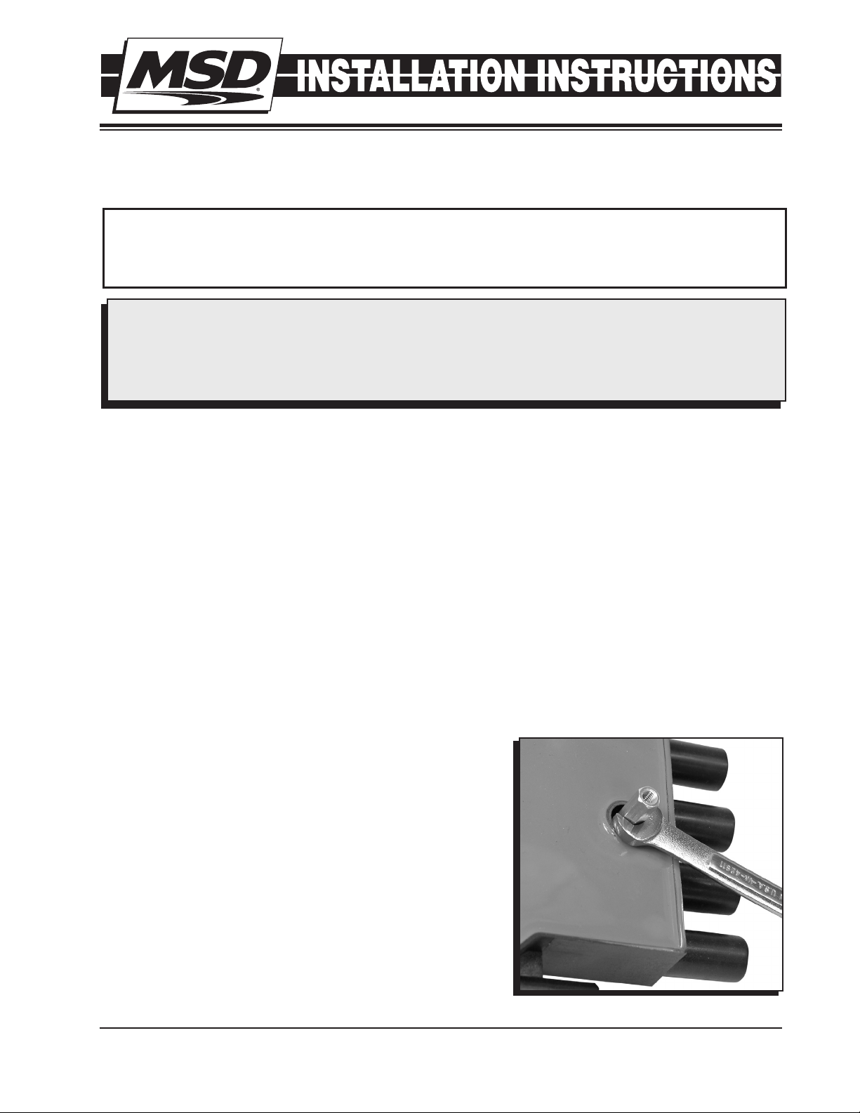
Figure 1 Removing the Original Cap.
M S D • W W W . M S D P E R F O R M A N C E . C O M • ( 9 1 5 ) 8 5 7 - 5 2 0 0 • F A X ( 9 1 5 ) 8 5 7 - 3 3 4 4
Page 2
2 INSTALLATION INSTRUCTIONS
connector.
15. Using the supplied special tool and a 1/4" wrench, remove
the four screws that hold the distributor cap to the engine
and pull the cap off (Figure 1).
16. Remove the two rotor screws and pull the rotor off. At
this time, the isolator assembly will slide off the housing.
INSTALLATION
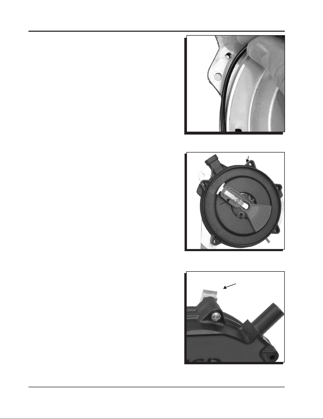
1. Locate and install the distributor-to-isolator seal then
position the isolator in place on the distributor (Figure 2).
2. Install the new rotor with the supplied hardware. The rotor
only installs one way. Make sure it sits squarely on the
shaft.
Note: It is recommended to use a threadlocker like Loctite
Blue on the two rotor screws.
3. Make sure that the Isolator-to-Cap seal is installed on the
isolator, then install the cap using the supplied Phillips
head screws (Figure 3).
4. Locate four metric Phillips screws that retain the cap
assembly. There is also a standard, slightly larger and
longer Phillips screw. This screw is used with the ClampBlock that goes in the cap tab located between the wiring
harness and the coil wire tower (Figure 4).
5. Note that the Clamp-Block has two different thicknesses
(Figure 5). Some distributor housings have a machined
surface while others are cast. Determine which side works
best in your application to secure the top mount of the
cap. Once the direction is achieved, slide the Clamp-Block
into position and screw the standard Phillips screw into
position (Figure 5).
6. Connect the distributor connector followed by the coil
wire and spark plug wires. Ensure that each wire is in the
correct location (Figure 6).
7. The distributor is assembled. Reinstall all of the
components in the reverse order. It is recommended to
follow along with your vehicle’s service manual.
Figure 2 Installing the
Distributor-to-Isolator Seal.
Figure 3 The Isolator-to-Cap Seal.
CLAMP BLOCK
LOCATION
Figure 4 Clamp-Block Mounting Boss.
M S D • W W W . M S D P E R F O R M A N C E . C O M • ( 9 1 5 ) 8 5 7 - 5 2 0 0 • F A X ( 9 1 5 ) 8 5 7 - 3 3 4 4
Page 3

INSTALLATION INSTRUCTIONS 3
EDGE
MUST SIT
FLUSH
WITH
HOUSING
NOTE
DIFFERENT
THICKNESSES
Figure 5 Installing the Clamp-Block.
COIL WIRE
4
6
8
2
1
5
3
7
Figure 6 Spark Plug Wire Location.
M S D • W W W . M S D P E R F O R M A N C E . C O M • ( 9 1 5 ) 8 5 7 - 5 2 0 0 • F A X ( 9 1 5 ) 8 5 7 - 3 3 4 4
Page 4

TECH NOTES
_________________________________________________________________________________________________________________________
_________________________________________________________________________________________________________________________
_________________________________________________________________________________________________________________________
_________________________________________________________________________________________________________________________
_________________________________________________________________________________________________________________________
_________________________________________________________________________________________________________________________
_________________________________________________________________________________________________________________________
_________________________________________________________________________________________________________________________
_________________________________________________________________________________________________________________________
_________________________________________________________________________________________________________________________
_________________________________________________________________________________________________________________________
_________________________________________________________________________________________________________________________
_________________________________________________________________________________________________________________________
_________________________________________________________________________________________________________________________
_________________________________________________________________________________________________________________________
_________________________________________________________________________________________________________________________
_________________________________________________________________________________________________________________________
_________________________________________________________________________________________________________________________
Service
In case of malfunction, this MSD component will be repaired free of charge according to the terms of the warranty.
When returning MSD components for warranty service, Proof of Purchase must be supplied for verification. After
the warranty period has expired, repair service is based on a minimum and maximum fee.
All returns must have a Return Material Authorization (RMA) number issued to them before
being returned. To obtain an RMA number please contact MSD Customer Service at 1 (888) MSD-7859 or visit
our website at www.msdperformance.com/rma to automatically obtain a number and shipping information.
When returning the unit for repair, leave all wires at the length in which you have them installed. Be sure to include
a detailed account of any problems experienced, and what components and accessories are installed on the vehicle.
The repaired unit will be returned as soon as possible using Ground shipping methods (ground shipping is covered
by warranty). For more information, call MSD at (915) 855-7123. MSD technicians are available from 7:00 a.m. to
5:00 p.m. Monday - Friday (mountain time).
Limited Warranty
M
SD warrants this product to be free from defects in material and workmanship under its intended normal use*,
when properly installed and purchased from an authorized MSD dealer, for a period of one year from the date of
the original purchase. This warranty is void for any products purchased through auction websites. If found to be
defective as mentioned above, it will be repaired or replaced at the option of MSD. Any item that is covered under
this warranty will be returned free of charge using Ground shipping methods.
This shall constitute the sole remedy of the purchaser and the sole liability of MSD. To the extent permitted by
law, the foregoing is exclusive and in lieu of all other warranties or representation whether expressed or implied,
including any implied warranty of merchantability or fitness. In no event shall MSD or its suppliers be liable for special
or consequential damages.
*Intended normal use means that this item is being used as was originally intended and for the original application
as sold by MSD. Any modifications to this item or if it is used on an application other than what MSD markets the
product, the warranty will be void. It is the sole responsibility of the customer to determine that this item will work for
the application they are intending. MSD will accept no liability for custom applications.
M S D • W W W . M S D P E R F O R M A N C E . C O M • ( 9 1 5 ) 8 5 7 - 5 2 0 0 • F A X ( 9 1 5 ) 8 5 7 - 3 3 4 4
© 2012 Autotr onic Contr ols Corpor ation
FRM30088 Revised 12/11 Printed in U.S.A.
 Loading...