

Page 1
MSD Modified Honda Distributor Cap
PN 82901, PN 82902, PN 82921 and PN 82922
Parts Included In This Kit:
1 - Distributor Cap
1 - Coil Wire
WARNING: During installation, disconnect the battery cables. When disconnecting the battery
cables, always remove the Negative cable first and install it last.
Note: The Modified Cap is designed so that you can remove the stock internal coil, and use a higher
output external coil. The stock internal coil MUST be removed before the installation of this
cap. Failure to do so will cause damage
to the MSD cap.
Note: The supplied spark plug style terminals
are required with the PN 82902 and PN
82922 caps.
1 - Parts Bag
1 - Mini-Stripper-Crimper
INSTALLATION:
1. Mark the location of each plug wire, then
remove the wires. Remove the stock distributor
cap, rotor and dust cover.
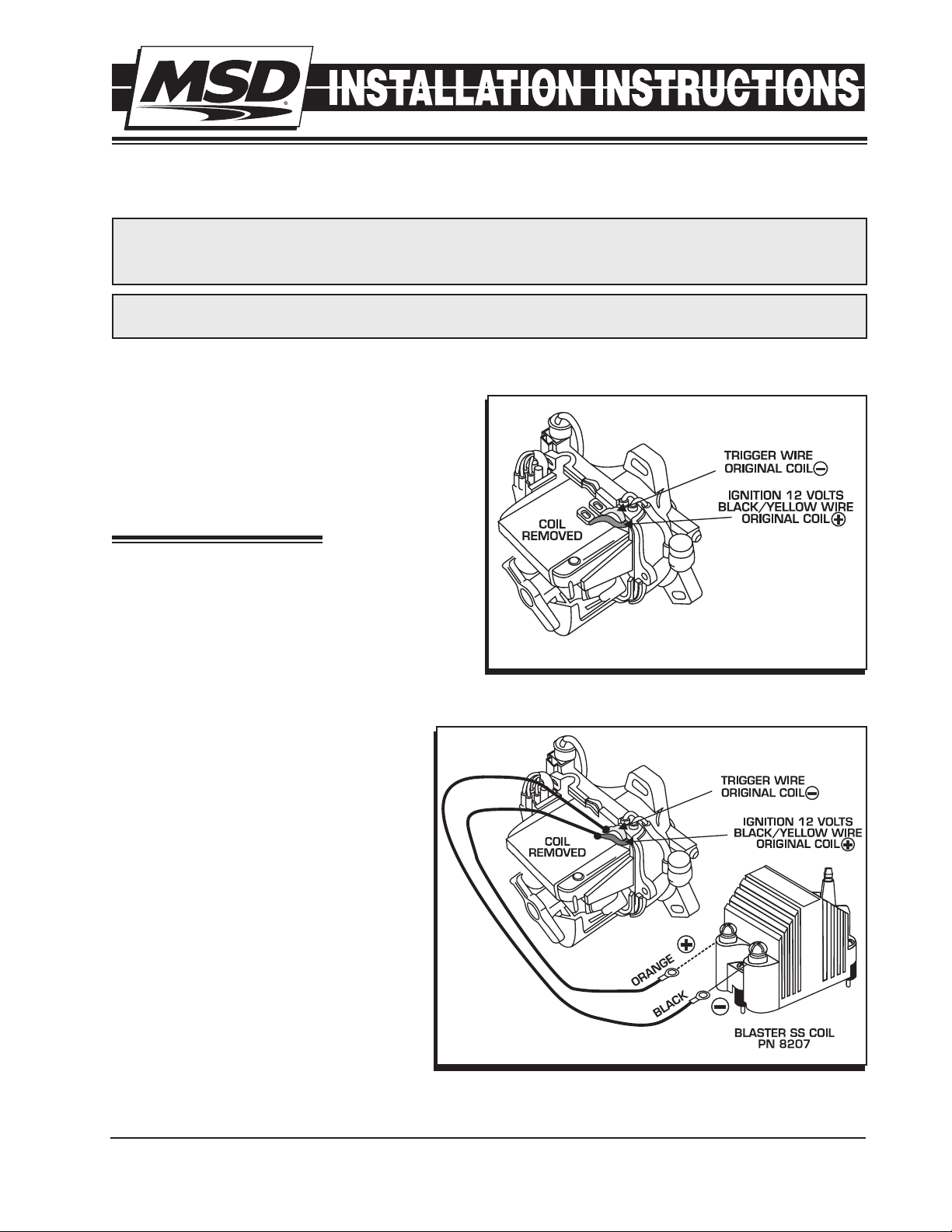
2. Locate the coil wires and note their color and
location. On the majority of Honda or Acura
engines, the Black/Yellow wire is positive. The
coil negative wire is generally White/Blue, Blue,
Green/Yellow or Green. In some cases, the coil
itself is marked negative (-) and positive (+).
Figure 1 Primary Wiring with the Coil Removed.
1 - Retainer and Screw
(Extreme Caps only)
Note: If you have a question as to the
wires’ polarity, use a volt-meter and
probe each wire with the ignition
key turned to the On position. Coil
positive will show 10-12 volts.
3. Once you determine the polarity of the
coil wires you will need to extend the
wires to reach the MSD coil. Cut the
factory terminals off and solder to a 14
gauge wire. Seal the soldered joint with
shrink sleeve or electrical tape.
4. Depending on the model of distributor
you have, you may need to drill a hole
in the new cap to route the wires out.
In some applications the factory rubber
seal is thick enough to cut and slide the
new wires out.
5. Install the rotor, the new cap and then
the wires. For Extreme model caps, install the wire retainer with the supplied screw.
M S D • W W W . M S D P E R F O R M A N C E . C O M • ( 9 1 5 ) 8 5 7 - 5 2 0 0 • F A X ( 9 1 5 ) 8 5 7 - 3 3 4 4
Figure 2 Wiring with a Blaster SS Coil.
Page 2
2 INSTALLATION INSTRUCTIONS
DUAL CRIMP
TERMINAL
STANDARD
TERMINAL
CONDUCTOR
CRIMP TABS
WIRE SLEEVE
CRIMP TABS
STANDARD
DUAL CRIMP
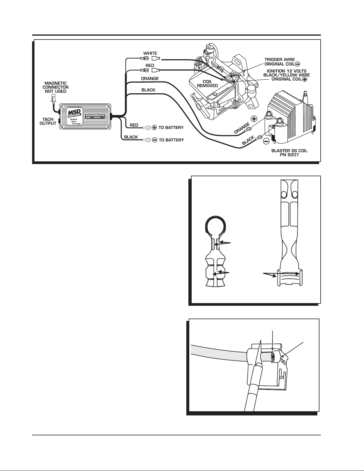
Figure 3 Wiring an MSD SCI Ignition with a Blaster SS Coil.
ASSEMBLING THE COIL WIRE
Once the cap is installed and the coil is wired, you
will need to assemble a coil wire. You will need a
razor blade and a 4-inch vice.
The Mini-Stripper-Crimper is an all in one spark plug
wire stripper and crimp tool. It will work with both
MSD 8.5mm Super Conductor and 8mm Heli-Core
wires to produce a strong, professional crimp.
TERMINALS
MSD offers several different terminals with our
Universal wire sets. There are two terminal styles
used, either a standard style or the Dual Crimp
Terminal (Figure 4). The standard design requires
stripping more of the wire sleeve because the
conductor will be bent under the terminal. The Dual
Crimp has specific crimp tabs for the conductor
which require needle nose pliers.
STRIPPING THE WIRE
1. Once you’ve determined which terminals you are
working with, position the wire in the corresponding
strip guide. There are two holes; one for the 8mm
wire and another for the 8.5mm wire.
2. There are two stripping positions indicated on the
stripping slot, depending on the terminal being
used. Slide the wire to the correct position and
strip the sleeve by holding a razor blade flush with
the strip guide and rotate the wire 360° (Figure
5).
3. Remove the wire and twist the cut end of the sleeve
off in a counterclockwise direction.
Figure 4 Identifying the Different Style Terminals.
Figure 5 Stripping the Sleeve.
M S D • W W W . M S D P E R F O R M A N C E . C O M • ( 9 1 5 ) 8 5 7 - 5 2 0 0 • F A X ( 9 1 5 ) 8 5 7 - 3 3 4 4
Page 3

INSTALLATION INSTRUCTIONS 3
TERMINAL
CRIMPING
To achieve the strongest crimp possible, it is required
to bend the crimp tabs over about 90° using needle
nose pliers (Figure 6). Follow the instructions for the
terminal you are using.
STANDARD TERMINALS
1. After stripping the sleeve, fold the conductor back
along the wire insulation (Figure 7).
2. Do not allow the conductor to pull tightly against
the insulation. A small gap around the conductor
should be present before crimping. Slide the wire
into the terminal with the conductor positioned
so it is in contact with the bottom of the terminal.
Position the wire through until the insulation
protrudes about 1/8" beyond the crimp tabs.
3. Position the wire and terminal into the "W" groove
of the Mini-Stripper Crimper and crimp.
Figure 6 Preparing the Terminals.
STANDARD
DUAL CRIMP TERMINALS
1. After stripping the sleeve, position the wire in
the terminal so the insulation protrudes about
1/8" beyond the insulation crimp tabs and the
conductor extends about 1/8" past the conductor
crimp tabs (Figure 8).
2. Position the wire and terminal into the "W" groove
of the Mini-Stripper Crimper and follow Steps 4 - 6
to crimp the terminal to the sleeve.
Note: It is normal for the conductor to retract into
the insulation slightly as the sleeve crimp is
made.
3. After the sleeve is crimped, push the conductor
between the crimp tabs and use a set of
needlenose pliers to crimp them together. DO
NOT OVER CRIMP.
4. Slide the other part of the Mini-Stripper-Crimper
over the wire terminal and lightly press them
together (Figure 9).
5. Put the assembly into a vise making sure the
alignment tabs are on the outside edge of the
vise jaws (Figure 9).
SMALL GAP
PLUG WIRE
BEND CONDUCTOR BACK
CRIMPING TABS 1/8”
PLUG WIRE
INSERT WIRE
Figure 7 Positioning the Wire in the Terminal.
DUAL CRIMP TERMINAL
POSITION WIRE
PLUG WIRE
CRIMP FIRST
1/8”
M S D • W W W . M S D P E R F O R M A N C E . C O M • ( 9 1 5 ) 8 5 7 - 5 2 0 0 • F A X ( 9 1 5 ) 8 5 7 - 3 3 4 4
PLUG WIRE
CRIMP SECOND
PLUG WIRE
Figure 8 Crimping a Dual Crimp Terminal
Page 4

ALIGNMENT TABS
6. Slowly close the vise making sure the tool and terminal stay properly positioned and aligned. Stop
applying pressure when the terminal ends have wrapped securely around the sleeve and grip the
wire.
Note: DO NOT OVER CRIMP! It is possible to tear the sleeve of the wire by excessive pressure on
the vise. This will cause a weaker crimp.
7. Back off the vise and remove the wire from the Crimper. Gently tug the terminal and inspect the
position of the conductor to make sure the crimp is solid and firm.
Figure 9 Crimping the Terminal.
Service
In case of malfunction, this MSD component will be repaired free of charge according to the terms of the warranty.
When returning MSD components for warranty service, Proof of Purchase must be supplied for verification. After
the warranty period has expired, repair service is based on a minimum and maximum fee.
All returns must have a Return Material Authorization (RMA) number issued to them before
being returned. To obtain an RMA number please contact MSD Customer Service at 1 (888) MSD-7859 or visit
our website at www.msdperformance.com/rma to automatically obtain a number and shipping information.
When returning the unit for repair, leave all wires at the length in which you have them installed. Be sure to include
a detailed account of any problems experienced, and what components and accessories are installed on the vehicle.
The repaired unit will be returned as soon as possible using Ground shipping methods (ground shipping is covered
by warranty). For more information, call MSD at (915) 855-7123. MSD technicians are available from 7:00 a.m. to
5:00 p.m. Monday - Friday (mountain time).
Limited Warranty
M
SD warrants this product to be free from defects in material and workmanship under its intended normal use*,
when properly installed and purchased from an authorized MSD dealer, for a period of one year from the date of
the original purchase. This warranty is void for any products purchased through auction websites. If found to be
defective as mentioned above, it will be repaired or replaced at the option of MSD. Any item that is covered under
this warranty will be returned free of charge using Ground shipping methods.
This shall constitute the sole remedy of the purchaser and the sole liability of MSD. To the extent permitted by
law, the foregoing is exclusive and in lieu of all other warranties or representation whether expressed or implied,
including any implied warranty of merchantability or fitness. In no event shall MSD or its suppliers be liable for special
or consequential damages.
*Intended normal use means that this item is being used as was originally intended and for the original application
as sold by MSD. Any modifications to this item or if it is used on an application other than what MSD markets the
product, the warranty will be void. It is the sole responsibility of the customer to determine that this item will work for
the application they are intending. MSD will accept no liability for custom applications.
M S D • W W W . M S D P E R F O R M A N C E . C O M • ( 9 1 5 ) 8 5 7 - 5 2 0 0 • F A X ( 9 1 5 ) 8 5 7 - 3 3 4 4
© 2012 Autotr onic Contro ls Corp orati on
FRM28974 Revised 01/12 Printed in U.S.A.
 Loading...