

Page 1
MSD 6LS-2 Ignition Controller for
Carbureted and EFI LS 2/LS 7 Engines
PN 6012
ONLINE PRODUCT REGISTRATION: Register your MSD product online. Registering your product
will help if there is ever a warranty issue with your product and helps the MSD R&D team create
new products that you ask for! Go to www.msdperformance.com/registration.
Parts Included
1 – Ignition Controller, PN 6012
1 – Pro-Data+ Software CD
1 – Harness
1 – Parts Bag
6 – Timing Modules
WARNING: During installation, disconnect the battery cables. When Disconnecting, always remove
the Negative cable first and install it last.
Note: Solid core spark plug wires or non-resistor spark plugs cannot be used with an MSD Ignition
Control.
Optional Accessories
Hand Held Monitor, PN 7550
Factory EFI Harness, PN 88862
CARBURETOR
The PN 6012 Ignition Controller is designed for GM LS 2/LS 7 based engines that have been retro-fit with
an intake manifold and carburetor. The Controller is supplied with a wiring harness that connects to the
factory connectors for a simple installation.
EFI
This Controller can also be used in stock, EFI applications, by using accessory Harness PN 88862. This
Harness allows the PN 6012 Controller to tap into the sensor signals without interrupting the OEM ECU.
The ECU and Fuel Injectors operate as normal while the PN 6012 controls the ignition and timing.
OPERATION
The MSD Controller offers several programmable features that allow rpm and timing adjustments. This can
be achieved through the supplied Pro-Data+ software via a PC or with the optional Hand Held Programmer,
PN 7550. Timing adjustments and selections can also be made with plug-in modules. Software installation,
operation and the programmable features of the Controller are explained in detail in this document. More
information can be found in the Pro-Data+ Software Help section.
MOUNTING
The Controller is designed to be mounted under the hood or on the firewall. Do not mount the unit near
exhaust. Four vibration mounts are supplied to mount the unit. Find a suitable location, confirm that all of
the wires reach their connections. Mark the mounting hole locations using the unit. Drill the holes with a
3/16" bit.
WIRING
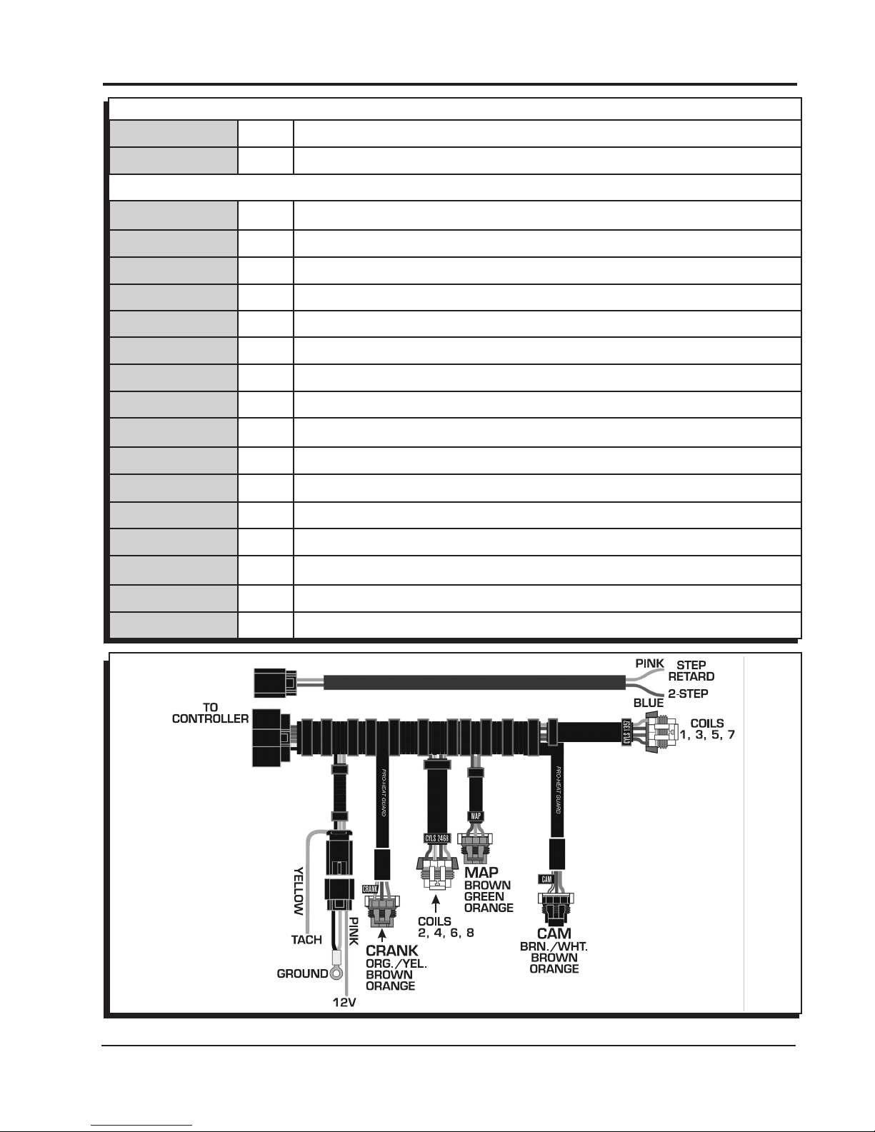
All of the wiring, except three wires, are routed into factory style connectors to ensure an easy installation.
The wire descriptions follow in the chart on pages 2 and 3.
MSD • WWW.MSDPERFORMANCE.COM • (915) 855-7123 • FAX (915) 857-3344
Page 2
2 INSTALLATION INSTRUCTIONS
LOOSE WIRES
BLACK/GRAY Pin-A/B Ground. Connect to a ground source, such as the engine or battery negative.
PINK Pin-C On/Off wire. Connect to a switched 12 volt source.
YELLOW Tach Signal. Provides a 12 volt square wave signal.
CRANKSHAFT SENSOR, 3-PIN
ORANGE/YELLOW
Pin-A Crank Sensor Signal
BROWN Pin-B Sensor Ground
ORANGE Pin-C 5 Volt Supply
CAMSHAFT SENSOR, 3-PIN
BROWN/WHITE Pin-C Cam Sensor Signal
BROWN Pin-B Sensor Ground
ORANGE Pin-A 5 Volt Supply
MAP CONNECTOR, 3-PIN (OPTIONAL)
BROWN Pin-A Sensor Ground
LT. GREEN Pin-B MAP Sensor Signal
ORANGE Pin-C 5 Volt Supply
COIL CONNECTOR, CYLINDERS 2, 4, 6, 8
BLACK Pin-A Ground
RED/GREEN Pin-B Coil-2
BROWN/GREEN
Pin-C Coil-4
BROWN Pin-E Sensor Ground
WHITE/BLUE Pin-F Coil-6
VIOLET/BLUE Pin-G Coil-8
PINK Pin-H 12 Volt Supply
Note: Pin-D is not used.
COIL CONNECTOR, CYLINDERS 1, 3, 5, 7
BLACK Pin-A Ground
RED Pin-B Coil-7
GREEN Pin-C Coil-5
BROWN Pin-E Sensor Ground
LT. BLUE Pin-F Coil-3
VIOLET Pin-G Coil-1
PINK Pin-H 12 Volt Supply
Note: Pin-D is not used.
MSD • WWW.MSDPERFORMANCE.COM • (915) 855-7123 • FAX (915) 857-3344
Page 3
INSTALLATION INSTRUCTIONS 3
2-PIN CONNECTOR, ACCESSORIES
PINK Pin-B Step Retard. When 12-volts are supplied, the Step Retard is activated.
BLUE Pin-A Two-Step. When 12-volts are supplied, the RevLaunch rpm value is active.
16-PIN CONNECTOR WIRE LOCATION
GRAY Pin-A Ground
PINK Pin-B 12 Volt Supply
BROWN/WHITE Pin-C Cam Sensor Signal
RED/GREEN Pin-D Coil-2
BROWN/GREEN
Pin-E Coil-4
WHITE/BLUE Pin-F Coil-6
VIOLET/BLUE Pin-G Coil-8
YELLOW Pin-H Tach
BROWN Pin-J Sensor Ground
LT. GREEN Pin-K MAP Sensor Signal
RED Pin-L Coil-7
GREEN Pin-M Coil-5
LT. BLUE Pin-N Coil-3
VIOLET Pin-P Coil-1
ORANGE/YELLOW
Pin-R Crank Sensor Signal
ORANGE Pin-S 5 Volt Supply
MSD • WWW.MSDPERFORMANCE.COM • (915) 855-7123 • FAX (915) 857-3344
Figure 1 Wiring the MSD 6LS-2 Controller.
Page 4

4 INSTALLATION INSTRUCTIONS
PRO-DATA+
Installation of the Pro-Data+ Software
1. Insert the installation CD into your PC.
2. In Windows, click on Start then select Run.
3. In the box type, “D: Setup” and press Enter (or corresponding drive).
4. The screen will walk you through several steps.
5. Once loaded, your monitor will have an MSD Graph View logo. Click on it to open the software.
6. A program will open. Go to the upper left corner of the screen and click on File, then Open.
7. This will open a menu of part numbers. Select “6012”.
8. This will open another menu of versions. Highlight and open the “6012vxx.IGN” (xx determines the
versions, such as 02). This will open the Pro-Data+ software for the Ignition Controller.
Saves and Transfers
Whenever a change is made to a program, it either must be saved to a file in your PC or it needs to be
transferred to the Controller. You will notice that whenever you make a change to a program, the bullet
next to the modified value will turn red. It will remain red until you save it to a file or to the Controller. There
are two ways to save your files.
Save to MSD: This step will save any changes directly into the Controller.
Save to PC: This will save your changes to only show on the PC screen (indicated by a red bullet point
next to any altered values). These modifications will not be active or saved until you save
the file or transfer the information to the MSD.
You can create numerous files on your PC and download them for testing purposes or save programs
you used at different races or events.
Real Time
Monitor
Notes
Menu
Tree
Gauges
MAP Advance Chart
Timing Map
Figure 2 Pro-Data+ Screen and Programming Windows.
MSD • WWW.MSDPERFORMANCE.COM • (915) 855-7123 • FAX (915) 857-3344
Page 5

INSTALLATION INSTRUCTIONS 5
PROGRAMMABLE FEATURES
The following explains the programmable features of the PN 6012 Controller. The features are listed
in the same order shown on the Data Editor list in the software. Note that the Help pull down menu
of the software offers explanations of all the features.
Note: STATS Stat 1 or SCAN are display features only used with the Hand Held Monitors, PN
7550, PN 7553.
RPM TABLE (RPMtbl)
Note: When plotting a timing curve by using the RPM Table or MAP Table through your PC, there must
NOT be a Timing Module installed. Power-up with a module installed will override the saved
timing plot.
This setting can only be modified from the RPM Timing Curve edit graph on the lower right of the
screen. It can also be set with the Hand Held Monitor. The chart allows you to map out an entire timing
curve, much like the centrifugal advance of a mechanical distributor.
To create a map, simply position the mouse at a point on the chart and right click to add a dot. By
moving the mouse over this point and a left click, the dot changes to red (active) and you can move
it around the map.
Note: The timing has minimum and maximum limits that are set in the Data Editor Menu. These
settings include the cumulative value of any vacuum advance or retard as well as the Step
Retard if used.
MAP TABLE (MAPtbl)
Note: In order to take advantage of a vacuum advance or retard, a MAP sensor is required.
Note: When plotting a timing curve by using the RPM Table or MAP Table through your PC, there must
NOT be a Timing Module installed. Power-up with a module installed will override the saved
timing plot.
This is a Manifold Absolute Pressure (MAP) chart. It gives you the capability of modifying the timing
curve based on manifold pressure (vacuum or boost). A curve can be created from the MAP Advance
Curve graph on the upper right of the screen. It can also be set with the Hand Held Monitor. The chart
allows you to map out an advance curve based on manifold vacuum (much like the vacuum advance
on a mechanical distributor).
To create a map, simply position the mouse at a point on the chart and right click to add a dot. By moving the
mouse over this point and a left click, the dot changes to red (active) and you can move it around the map.
Note: The timing has minimum and maximum limits that are set in the Data Editor Menu. These
settings include the cumulative value of any vacuum advance or retard as well as the Step
Retard if activated.
MAP SENSOR SELECT
Allows the selection of a 2, 3, or 4-bar MAP sensor. This setting should be set to match the MAP
Sensor in use: 2-bar (2-20 psia), 3-bar (2-30 psia) or 4-bar (2-45 psia). GM Part Numbers 12615136
and 12580698 are 2-bar sensors that connect to the MSD harness.
TIMING LIMIT
There are two adjustments that set the limits of ignition timing. These settings are meant as safety
targets to keep the timing in check. Both the Minimum and Max values include any timing retards or
advancements.
Min Timing This is minimum amount of timing advance. It is adjustable from 0°-20° BTDC
with a default of 5°.
Max Timing This is the maximum amount of timing advance. It is adjustable from 25°-65°
BTDC with a default of 45°.
MSD • WWW.MSDPERFORMANCE.COM • (915) 855-7123 • FAX (915) 857-3344
Page 6
6 INSTALLATION INSTRUCTIONS
REV LIMITS
The Controller allows you to program two rev limits; one for an over-rev safety and another that
provides a low limit for use as a hole-shot, or two step limit.
RevLaunch This is the low rpm limit that is designed to be used while staged at the starting
line. It is activated when the Blue wire is connected to 12 volts. When voltage is
removed from this wire, the High Rev Limit is active. It is adjustable in 100 rpm
increments from 2,000 - 12,500 rpm.
RevMax This is the high, or over-rev rpm limit. It is active whenever the Blue wire (Launch
Rev Limit) is not connected to 12 volts. It is adjustable in 100 rpm increments
from 2,000 - 12,500 rpm.
STEP RETARD
A step retard will provide an adjustable amount of retard at a specific moment. This is ideal when
using nitrous oxide. The amount of retard is adjustable from 0° - 15° in 1° increments. The retard is
activated when the Pink wire is switched to 12 volts. Default is 10°.
IDLE TIMING CONTROL
This is defaulted at Control DISABLE. When switched to ENABLE, the controller will alter the ignition
timing constantly to search for the best idle qualities.
Note: This is a function of an ECU controlled system and should be enabled when used with an
OEM EFI application.
COIL SELECT
There are several coils that can be used on these engines. The 6LS-2 lets you program which coil
is being used for the best performance.
LS 2 Select when using factory LS 2 coils or MSD PN 82478. This is the default.
LS 1 Select when using factory style LS 1 or MSD PN 82468.
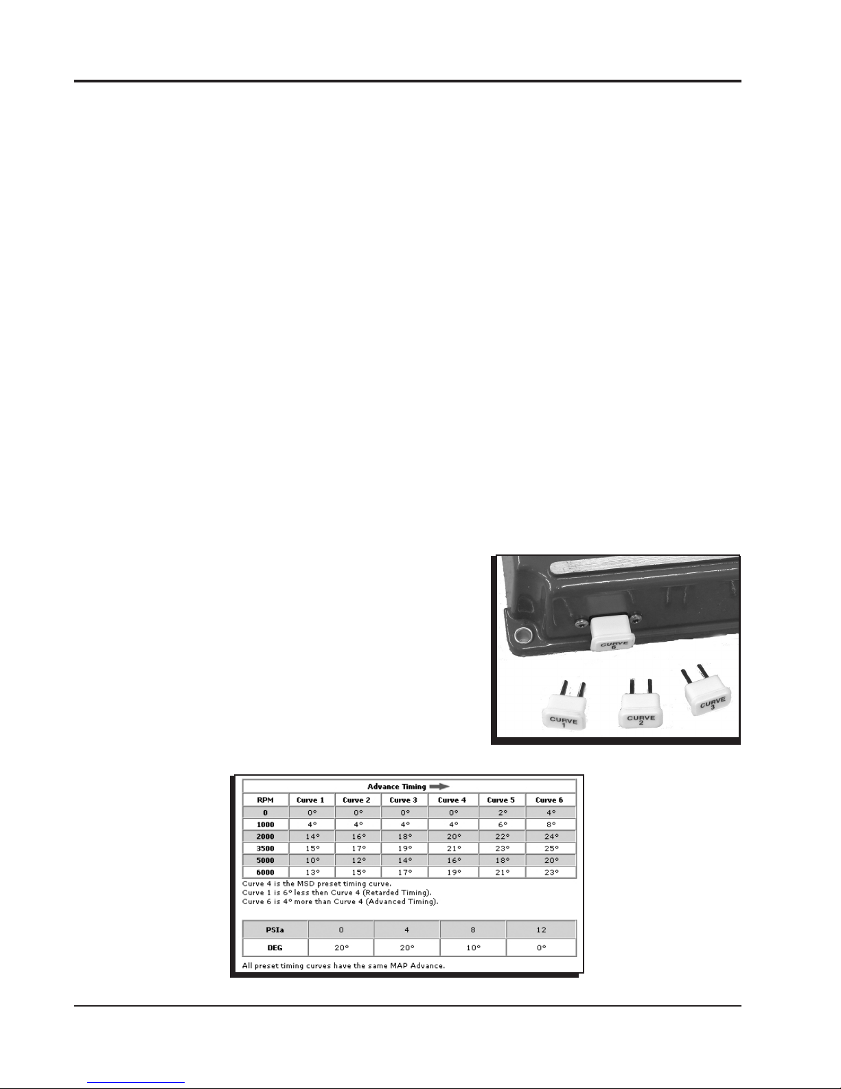
TIMING CURVE MODULES
The PN 6012 Controller is supplied with six modules that
plug into the side of the housing (Figure 3). The modules
are labeled Curve 1, Curve 2, etc. By plugging in one of the
modules, the timing curve will be set with a pre-programmed
curve upon power-up of the Controller. (Removing the module
while the engine is running will not affect the timing curve.)
Figure 4 shows each of the timing curves.
Note: Any updates that are made using the PC software will
be overridden if a module is left plugged in during
power-up of the Controller.
Figure 3 Timing Curve Modules.
MSD • WWW.MSDPERFORMANCE.COM • (915) 855-7123 • FAX (915) 857-3344
Figure 4 Timing Curves from the Modules.
Page 7

INSTALLATION INSTRUCTIONS 7
TECH NOTES
_________________________________________________________________________________________________________________________
_________________________________________________________________________________________________________________________
_________________________________________________________________________________________________________________________
_________________________________________________________________________________________________________________________
_________________________________________________________________________________________________________________________
_________________________________________________________________________________________________________________________
_________________________________________________________________________________________________________________________
_________________________________________________________________________________________________________________________
_________________________________________________________________________________________________________________________
_________________________________________________________________________________________________________________________
_________________________________________________________________________________________________________________________
_________________________________________________________________________________________________________________________
_________________________________________________________________________________________________________________________
_________________________________________________________________________________________________________________________
_________________________________________________________________________________________________________________________
_________________________________________________________________________________________________________________________
_________________________________________________________________________________________________________________________
_________________________________________________________________________________________________________________________
_________________________________________________________________________________________________________________________
_________________________________________________________________________________________________________________________
_________________________________________________________________________________________________________________________
_________________________________________________________________________________________________________________________
_________________________________________________________________________________________________________________________
_________________________________________________________________________________________________________________________
_________________________________________________________________________________________________________________________
_________________________________________________________________________________________________________________________
_________________________________________________________________________________________________________________________
_________________________________________________________________________________________________________________________
_________________________________________________________________________________________________________________________
_________________________________________________________________________________________________________________________
_________________________________________________________________________________________________________________________
_________________________________________________________________________________
_________________________________________________________________________________________________________________________
_________________________________________________________________________________________________________________________
_________________________________________________________________________________________________________________________
_________________________________________________________________________________________________________________________
_________________________________________________________________________________________________________________________
_________________________________________________________________________________________________________________________
MSD • WWW.MSDPERFORMANCE.COM • (915) 855-7123 • FAX (915) 857-3344
Page 8
TECH NOTES
_________________________________________________________________________________________________________________________
_________________________________________________________________________________________________________________________
_________________________________________________________________________________________________________________________
_________________________________________________________________________________________________________________________
_________________________________________________________________________________________________________________________
_________________________________________________________________________________________________________________________
_________________________________________________________________________________________________________________________
_________________________________________________________________________________________________________________________
_________________________________________________________________________________________________________________________
_________________________________________________________________________________________________________________________
_________________________________________________________________________________________________________________________
_________________________________________________________________________________________________________________________
_________________________________________________________________________________________________________________________
_________________________________________________________________________________________________________________________
_________________________________________________________________________________________________________________________
_________________________________________________________________________________________________________________________
_________________________________________________________________________________________________________________________
_________________________________________________________________________________________________________________________
Service
In case of malfunction, this MSD component will be repaired free of charge according to the terms of the warranty.
When returning MSD components for warranty service, Proof of Purchase must be supplied for verification. After
the warranty period has expired, repair service is based on a minimum and maximum fee.
All returns must have a Return Material Authorization (RMA) number issued to them before
being returned. To obtain an RMA number please contact MSD Customer Service at 1 (888) MSD-7859 or visit
our website at www.msdperformance.com/rma to automatically obtain a number and shipping information.
When returning the unit for repair, leave all wires at the length in which you have them installed. Be sure to include
a detailed account of any problems experienced, and what components and accessories are installed on the vehicle.
The repaired unit will be returned as soon as possible using Ground shipping methods (ground shipping is covered
by warranty). For more information, call MSD at (915) 855-7123. MSD technicians are available from 7:00 a.m. to
5:00 p.m. Monday - Friday (mountain time).
Limited Warranty
MSD warrants this product to be free from defects in material and workmanship under its intended normal use*,
when properly installed and purchased from an authorized MSD dealer, for a period of one year from the date of
the original purchase. This warranty is void for any products purchased through auction websites. If found to be
defective as mentioned above, it will be repaired or replaced at the option of MSD. Any item that is covered under
this warranty will be returned free of charge using Ground shipping methods.
This shall constitute the sole remedy of the purchaser and the sole liability of MSD. To the extent permitted by
law, the foregoing is exclusive and in lieu of all other warranties or representation whether expressed or implied,
including any implied warranty of merchantability or fitness. In no event shall MSD or its suppliers be liable for special
or consequential damages.
*Intended normal use means that this item is being used as was originally intended and for the original application
as sold by MSD. Any modifications to this item or if it is used on an application other than what MSD markets the
product, the warranty will be void. It is the sole responsibility of the customer to determine that this item will work for
the application they are intending. MSD will accept no liability for custom applications.
MSD • WWW.MSDPERFORMANCE.COM • (915) 855-7123 • FAX (915) 857-3344
FRM28204 Revised 01/14 Printed in U.S.A.
© 2014 MSD LLC
 Loading...