

Page 1
Universal Wire Set for GM
GEN III Engines
PN 32079 / PN 32073
Parts Included In This Kit:
8 - Spark Plug Wires with 90° and Multi-Angle Boots
9 - LS1 Boots and Terminals
1 - Mini-Stripper-Crimper
9 - Terminal Insert Guides
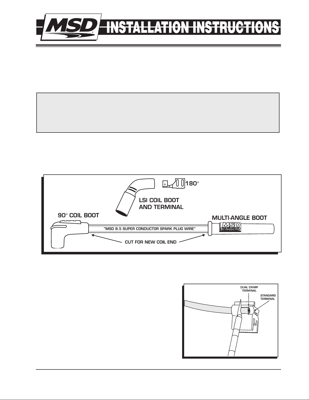
This Universal Wire set gives you the choice of using a 90° or straight/Multi-Angle boot and
terminal on the spark plug to accommodate for the header variances. Once you have determined
the style boots to use, you can cut the new wires to length then install the correct supplied coil
terminal and boot. A Mini-Stripper-Crimper Tool is supplied to help you achieve a strong, factory
type crimp.
Tools Required:
Razor Blade
Vise (4" Minimum)
Needlenose Pliers
Optional:
PN 35051 Pro Crimp Tool
Figure 1 Choosing the Spark Plug Boots and Terminals.
1. Once you’ve determined wire length and spark plug
boot to use, position the wire in the corresponding strip
guide of the strip tool.
2. There are two stripping positions on the stripping slot,
when installing the LS1 terminal it will require you to strip
the wire at standard terminal length (Figure 2).
3. Remove the wire and twist the cut sleeve off in a counterclockwise direction.
Figure 2 Stripping the Sleeve.
M S D • W W W . M S D P E R F O R M A N C E . C O M • ( 9 1 5 ) 8 5 7 - 5 2 0 0 • F A X ( 9 1 5 ) 8 5 7 - 3 3 4 4
Page 2
2 INSTALLATION INSTRUCTIONS
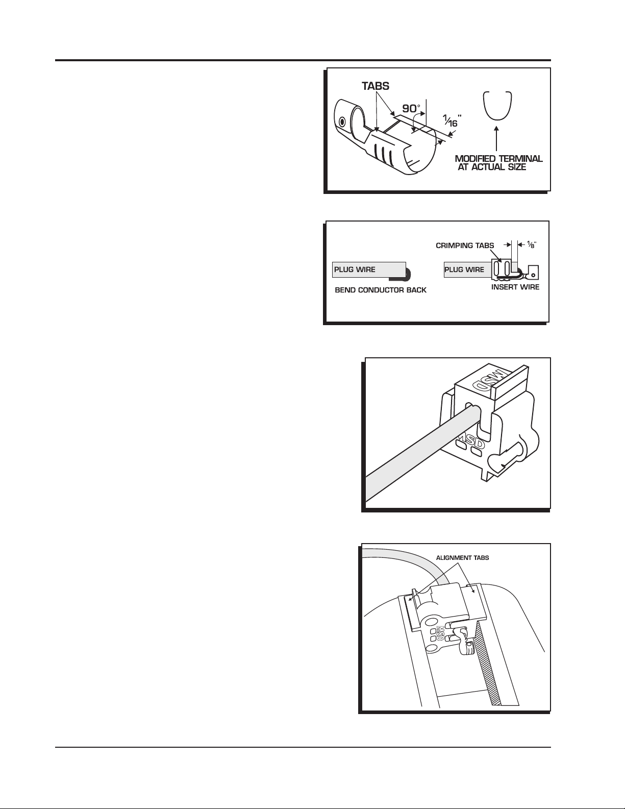
4. To achieve the strongest crimp possible, it is required
to bend the crimp tabs over about 90° using needle
nose pliers. Figure 3 shows an example.
Figure 3 Stripping the Sleeve.
5. Bend the conductor back along the wire insulation.
Slide the wire into the terminal with the conductor
positioned so it is in contact with the bottom of
the terminal (Figure 4). Push the wire through until
the sleeve protrudes about 1/8” beyond the crimp
tabs.
Figure 4 Preparing the Terminals.
6. Position the wire and terminal into the “W” groove
side of the Mini-Stripper-Crimper. Align the crimp
tabs so they are exactly centered on the tip of the
crimp die (Figure 5).
7. Slide the other part of the Mini-Stripper-Crimper over
the wire terminal and lightly press them together.
8. Put the assembly into a vise making sure the alignment tabs are on the outside edge of the vise jaws
(Figure 6).
9. Slowly close the vise making sure the tool and
terminal stay properly positioned and aligned
(Figure 6). Stop applying pressure when the
terminal ends have wrapped securely around the
sleeve and grip the wire.
Figure 5 Aligning the Terminal in the Tool.
Figure 6 Aligning the Terminal in the Tool.
M S D • W W W . M S D P E R F O R M A N C E . C O M • ( 9 1 5 ) 8 5 7 - 5 2 0 0 • F A X ( 9 1 5 ) 8 5 7 - 3 3 4 4
Page 3

INSTALLATION INSTRUCTIONS 3
Note: DO NOT OVER-CRIMP! It is possible to tear the sleeve of the wire by excessive pressure on the
vise. This will cause a weaker crimp.
10. Back off the vise and remove the wire from the Crimper. Gently tug the terminal and inspect the
position of the conductor to make sure the crimp is solid and firm.
11. With the terminal crimped to the wire securely, push the boot over the terminal and over the sleeve
of the wire until the terminal protrudes past the boot. A drop of dielectric grease or silicone spray
will assist in sliding the boot in place.
12. Locate the supplied terminal insert guides, the small plastic sleeves, supplied with the kit. These
help ensure a positive connection to the mating coil terminal. Figure 7 illustrates their installation.
ALIGN SLOT WITH
CRIMP TAB CREASE
CHAMFER
EDGE OUT
PUSH UNTIL IT
SNAPS IN PLACE
Figure 7 Boot & Installation and Terminal Depth.
TECH NOTES
M S D • W W W . M S D P E R F O R M A N C E . C O M • ( 9 1 5 ) 8 5 7 - 5 2 0 0 • F A X ( 9 1 5 ) 8 5 7 - 3 3 4 4
Page 4

TECH NOTES
_________________________________________________________________________________________________________________________
_________________________________________________________________________________________________________________________
_________________________________________________________________________________________________________________________
_________________________________________________________________________________________________________________________
_________________________________________________________________________________________________________________________
_________________________________________________________________________________________________________________________
_________________________________________________________________________________________________________________________
_________________________________________________________________________________________________________________________
_________________________________________________________________________________________________________________________
_________________________________________________________________________________________________________________________
_________________________________________________________________________________________________________________________
_________________________________________________________________________________________________________________________
_________________________________________________________________________________________________________________________
_________________________________________________________________________________________________________________________
_________________________________________________________________________________________________________________________
_________________________________________________________________________________________________________________________
_________________________________________________________________________________________________________________________
_________________________________________________________________________________________________________________________
Service
In case of malfunction, this MSD component will be repaired free of charge according to the terms of the warranty.
When returning MSD components for warranty service, Proof of Purchase must be supplied for verification. After
the warranty period has expired, repair service is based on a minimum and maximum fee.
All returns must have a Return Material Authorization (RMA) number issued to them before
being returned. To obtain an RMA number please contact MSD Customer Service at 1 (888) MSD-7859 or visit
our website at www.msdperformance.com/rma to automatically obtain a number and shipping information.
When returning the unit for repair, leave all wires at the length in which you have them installed. Be sure to include
a detailed account of any problems experienced, and what components and accessories are installed on the vehicle.
The repaired unit will be returned as soon as possible using Ground shipping methods (ground shipping is covered
by warranty). For more information, call MSD at (915) 855-7123. MSD technicians are available from 7:00 a.m. to
5:00 p.m. Monday - Friday (mountain time).
Limited Warranty
M
SD warrants this product to be free from defects in material and workmanship under its intended normal use*,
when properly installed and purchased from an authorized MSD dealer, for a period of one year from the date of
the original purchase. This warranty is void for any products purchased through auction websites. If found to be
defective as mentioned above, it will be repaired or replaced at the option of MSD. Any item that is covered under
this warranty will be returned free of charge using Ground shipping methods.
This shall constitute the sole remedy of the purchaser and the sole liability of MSD. To the extent permitted by
law, the foregoing is exclusive and in lieu of all other warranties or representation whether expressed or implied,
including any implied warranty of merchantability or fitness. In no event shall MSD or its suppliers be liable for special
or consequential damages.
*Intended normal use means that this item is being used as was originally intended and for the original application
as sold by MSD. Any modifications to this item or if it is used on an application other than what MSD markets the
product, the warranty will be void. It is the sole responsibility of the customer to determine that this item will work for
the application they are intending. MSD will accept no liability for custom applications.
M S D • W W W . M S D P E R F O R M A N C E . C O M • ( 9 1 5 ) 8 5 7 - 5 2 0 0 • F A X ( 9 1 5 ) 8 5 7 - 3 3 4 4
© 2013 Autotr onic Co ntrols Corpor ation
FRM30048 Revised 02/13 Printed in U.S.A.
 Loading...