

Page 1
Atomic LS7 EFI Master Kit
DANGER
PN 2960
ONLINE PRODUCT REGISTRATION: Register your MSD product online. Registering your product
will help if there is ever a warranty issue with your product and helps the MSD R&D team create
new products that you ask for! Go to www.msdperformance.com/registration.
Thank you for selecting the Atomic LS EFI System! MSD’s Atomic EFI systems are designed with two
major goals; to simplify installation of EFI and deliver better overall performance from your engine.
Simplicity is achieved through wired-less technology to ease installation plus the Atomic is simple
to program with no PC required! Performance is delivered through advanced control of the fuel and
ignition, just as you’d expect from MSD.
Parts Included:
2 - Fuel Rail Assemblies
1 - Power Module
1 - Handheld Monitor
1 - Wideband O2 Sensor
1 - Weld - in O2 Sensor Bung,
Plug, and Crush Washer
1 - CAN Cable
1 - 4x Cam Sensor Harness
1 - 58x Crank Sensor Harness
2 - MAP Sensor Harnesses
4 - Injector Harnesses
1 - IAT Sensor and Grommet
1 - 4GB Micro SD Card
1 - TPS Sensor Harness
4 - Grommets, Sleeves, and
Mounting Screws
4 - Fuel Rail Brackets
8 - Injector Retainer Clips
1 - Spacer
1 - Shim Kit
8 - 6mm x 12mm Screws
8 - 8/32” Socket Head Cap
Screws
4 - M6 x 100mm Intake Bolts
4 - 6mm x 16mm Hex Head
Bolts
4 - #12 Washers
2 - 90º -6AN Fittings
1 - 15” High Pressure Fuel Hose
Parts Required, Not Included:
Fuel System: Fuel Pump, Fuel
Filter, Injectors, Injector
O-Rings,
Regulator, and Fuel Line.
Thread sealer for intake bolts.
Not legal for use on pollution controlled vehicles: The MSD Atomic EFI system is not CARB
approved for use on emission controlled vehicles.
modifications must be carried out by a qualified automotive technician. Installation of fuel system
parts requires handling of gasoline. Ensure that work is performed in a well ventilated area with an
approved fire extinguisher nearby. Extinguish all open flames, prohibit smoking and eliminate all
sources of ignition in the area of the vehicle before beginning the installation. When working with
fuel systems, eye goggles and other safety apparel should be worn to protect against debris and
sprayed gasoline. The finished work must be thoroughly checked to ensure there are no fuel leaks.
MSD • WWW.ATOMICEFI.COM • (915) 855-7123 • FAX (915) 857-3344
WARNING
Installation of this product requires detailed knowledge of automotive systems
and repair procedures. Installation of fuel system parts and any fuel tank
Page 2
2 INSTALLATION INSTRUCTIONS
EF
GH
DLPHI
DLPHI
EF
GH
EF
GH
DLPHI
DLPHI
CAPABILITIES
The Atomic LS7 kit is designed to fit the original equipment intakes. The Atomic LS7 kit is a self
integrated Fuel and Ignition controller for GEN-IV motors that requires no programming with a PC. The
interface is controlled through a supplied hand held controller. The ECU only needs basic configuration
information. Once the engine warms up to operating temperature, the ECU tunes itself off of its basic
configuration to ensure the best performance and throttle response for your engine. The atomic will
adjust timing and fuel curves on the fly which in turn produces the smoothest idle, best fuel economy,
and superior wide open throttle performance at all times. This also means that weather and altitude
changes aren’t a problem with this system.
The Atomic LS7 kit uses all OE sensors with the exception of the wideband O2 sensor and the Intake
Air Temperature sensor (IAT) supplied with the kit. The Atomic LS7 system only supports a cable
driven throttle body at this time.
Note: The drive-by-wire throttle body will have to be converted to a cable drive throttle body like the
MSD PN 2940.
COMPONENTS
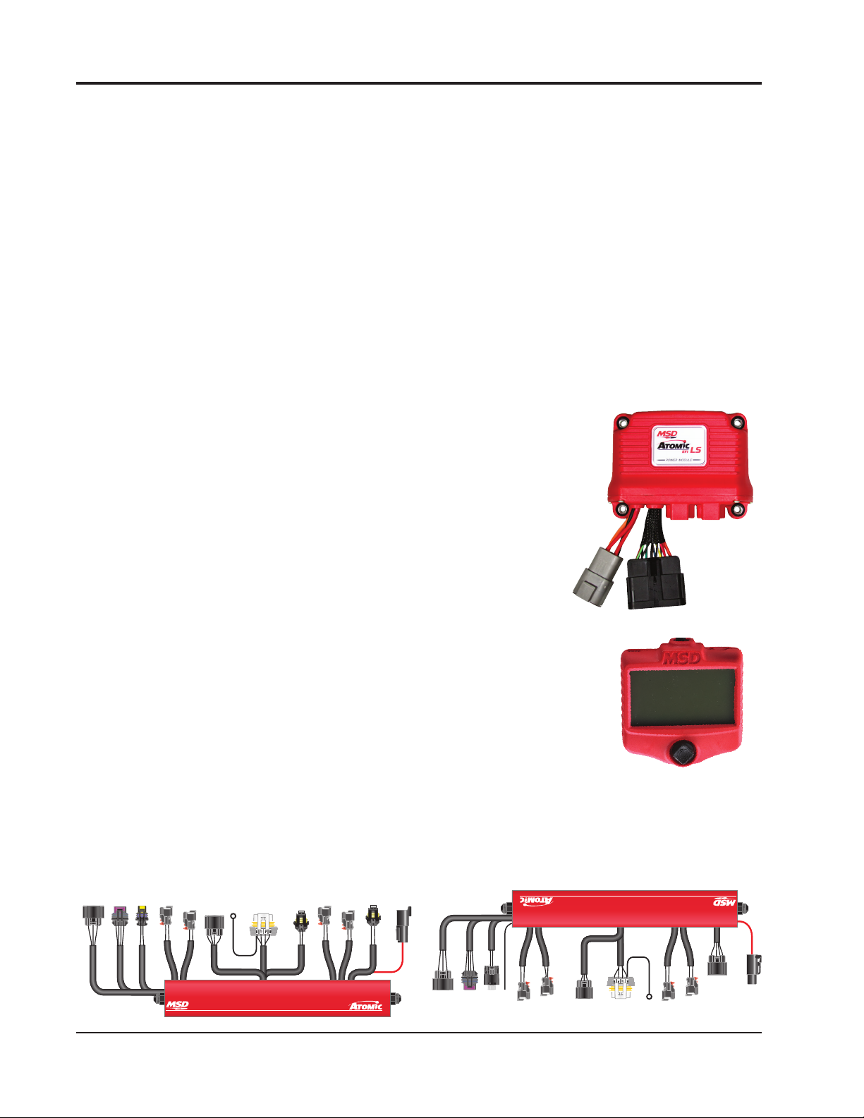
Power Module: The Power Module of the Atomic LS7 is the
communication hub of the system and provides the high current
fuel pump circuit and other input/outputs for optional features. The
unit has two ports for the MSD CAN system as well as a wiring
harness. There are connections for the WB02, the Handheld
Monitor as well as Rail Power and CAN communication to the
integrated fuel rails.
Handheld Programmer: The Atomic LS7 is a self-tuning fuel and
ignition control system. The system only needs the basic engine
configuration information to build a fuel table for the engine. The
Handheld Programmer is used to enter all the engine parameters
into the ECU, and uses the MSD CAN to communicate with the ECU. Once
the engine has been started and warmed up to operating temperature,
the ECU will monitor the sensors. The ECU will then adjust the fuel table
and ignition in order to maintain a properly running engine.
Power
Module
Fuel Rails/ECU: The Fuel Rails/ECU is combination of the electronics that drive
an ECU and a fuel rail assembly built into one unit. All of the engine sensor
connectors (except for the wideband O2 which connects to the Power
Module directly) are found on the fuel rails. The fuel rails are equipped
with -6AN fittings, but will accept -8AN fittings (the internal rail orifice is
Handheld
Programmer
the same diameter as the -8AN).
MSD • WWW.MSDPERFORMANCE.COM • (915) 855-7123 • FAX (915) 857-3344
Drivers Side Fuel Rail Passenger Side Fuel Rail
Page 3
INSTALLATION INSTRUCTIONS 3
COVER
COVER
FUEL RAILFUEL RAIL
LIFT THIS SIDE OF
COVER ENOUGH TO
CLEAR FUEL RAIL
PUSH COVER
Figure 1
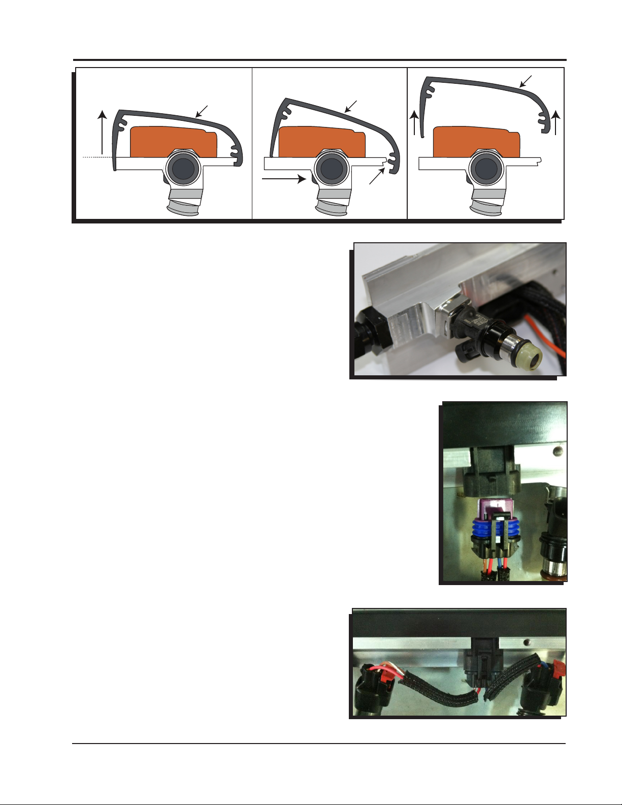
PREPARING THE FUEL RAILS FOR INSTALLATION
1. Lift the rounded end of the rail cover off of the fuel
rail (Figure 1).
2. Lubricate the o-rings on the injectors with some
motor oil or silicone lubricant. Install the injector
retainer clips onto the injectors. The injector clips
will automatically secure the injector to the fuel rail
when they are inserted into the bung (Figure 2).
3. Install the clips onto the injector before they are
pushed into the fuel rail bung. The injector clip will
automatically secure the injector to the rail.
4. Lubricate the o-rings on the injectors with some
motor oil or silicone lubricant and push the fuel
injectors into the bung without forcing them on. The
injectors should slide in easily. Use the injector clips
to lock the injectors onto the fuel rails (Figure 2).
WARNING: Forcing the injectors into the bung can
damage the o-rings, which can cause an engine fire.
5. Plug the fuel injector pigtails into the fuel rail
connections (Figure 3).
6. Connect the fuel injector pigtails to the injectors. The
long wires connect to the injectors on each end of
the fuel rail. The short wires connect to two inner
injectors (Figure 4).
COVER
FUEL RAILFUEL RAIL
DISENGAGE
FROM FUEL
RAIL
LIFT COVER UP
FUEL RAILFUEL RAIL
Figure 2
Figure 3
Figure 4
MSD • WWW.ATOMICEFI.COM • (915) 855-7123 • FAX (915) 857-3344
Page 4
4 INSTALLATION INSTRUCTIONS
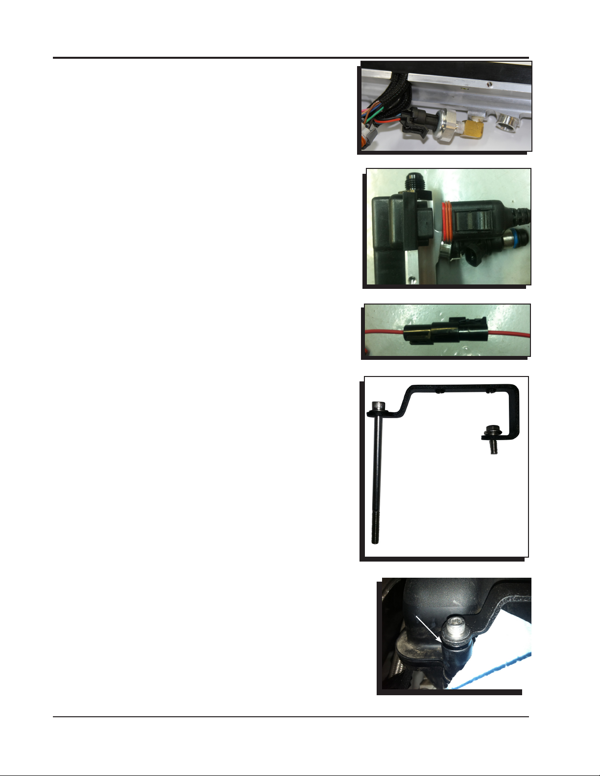
7. Plug the FPS connector into the fuel pressure sensor under
the fuel rail (Figure 5).
8. Connect the CAN cable from one rail to the other (Figure
6).
9. Connect the heavy red Rail Power wires together between
the two rails (Figure 7).
FUEL RAIL INSTALLATION
1. Preassemble the rail brackets with a washer and the M6 x
100MM bolts on the angled end. Use a single 6mm x 16mm
hex head bolt on the closed end of the flange. Coat the ends
of the 100mm bolts with thread sealant (Figure 8).
2. Place the spacer/bushing/rail bracket assemblies onto the
intake manifold. The angled end of the bracket is always
facing to the left when installed correctly on either side of
the engine. The rear passenger bracket will require a spacer
between the intake manifold and the bracket (Figure 9)
Figure 5
Figure 6
Figure 7
Figure 8
SPACER
Figure 9
MSD • WWW.MSDPERFORMANCE.COM • (915) 855-7123 • FAX (915) 857-3344
Page 5
INSTALLATION INSTRUCTIONS 5
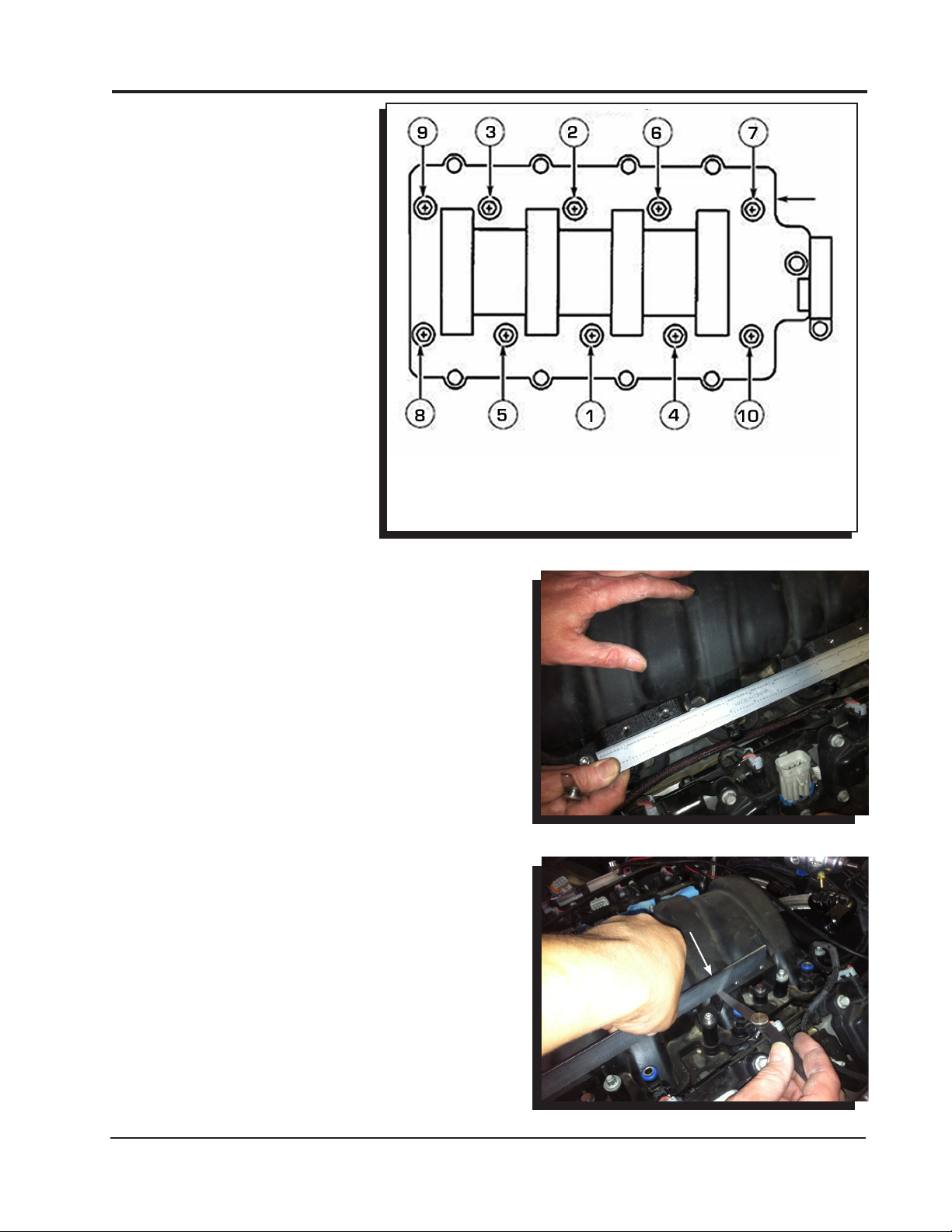
FRONT
1ST PASS: 42 IN LB - 44 IN LB
2ND PASS: 87 IN LB - 89 IN LB
3. Use the provided torque sequence to torque the
manifold bolts down correctly. Bolts #9 and #10 will
use the stock length bolts/bushings (Figure 10).
4. Check the rail brackets for alignment with a straight
edge (Figure 11).
5. Check the rail brackets for the correct installation
height with a feeler gauge. If there is more than
.015” of clearance, use a shim from the shim kit to
correct (Figure 12).
6. Install the rails onto the manifold. Use the supplied
6mm bolts to secure the rails to the rail brackets.
Torque to 85 in lb – 87 in. lb.
STOP HERE
Figure 10
Figure 11
.015"
Figure 12
MSD • WWW.ATOMICEFI.COM • (915) 855-7123 • FAX (915) 857-3344
Page 6
6 INSTALLATION INSTRUCTIONS
7. STOP. Visually inspect and ensure all the injectors are
sitting evenly and the injector o-rings are not pinched
or visible. Failure to install the injectors correctly can
result in an engine fire.
8. Begin routing the sensor harnesses and plugging
them into the appropriate sensors.
9. Snap the rail covers in place and secure them onto
the fuel rails with the supplied 8/32” socket head cap
screws (Figure 13).
10. Secure the front cover onto the fuel rail with the
supplied 8/32” socket head cap screws. Install the
back rail cover plate onto the assembly and secure it
with the supplied socket head cap screws.
Figure 13
FUEL RAIL/ECU WIRING
The Atomic LS7 kit has several harnesses to install with the different variations of the OE sensors.
These adapter harnesses plug into the connectors found on the rails themselves. The IAC and TPS
connectors are on both rails to accommodate the different throttle body configurations.
Air Conditioning kick up (AC): When 12v is applied to the AC kick up wire, the ECU will kick up the
and ground the red Fan 1 wire to compensate for the engine load change created by the AC
compressor.
Alternator: The kit plugs directly into the factory GM alternator.
Cam Sensor: The kit supports the 4x cam sensors. The easiest way to identify the cam sensor on
a stock engine would be by locating the sensor on the motor. The 4x sensor is mounted on
the timing chain cover.
Controller area network (CAN): The kit utilizes a CAN communication for wiring between the fuel
rails/ECU and the Power module.
Crank sensor: The kit supports the 58x crankshaft trigger wheels.
Engine Coolant Temperature (ECT) sensor: The engine coolant temperature is monitored by the
ECU for fuel and ignition adjustments in closed loop operation.
Fuel Pressure (FP) Sensor: The kit includes a fuel pressure sensor which is already installed on the
driver side fuel rail.
Idle Air Control (IAC) Sensor: The kit has a connector on each rail to accommodate different intake
styles. IAC must be plugged into the driver side connector.
Ignition Coils: The kit has a factory connector that will connect to the factory coil bracket harness
on each valve cover (not supplied with the kit). There is an extra ground wire with each coil
bracket connector that should be grounded to the back of each cylinder head.
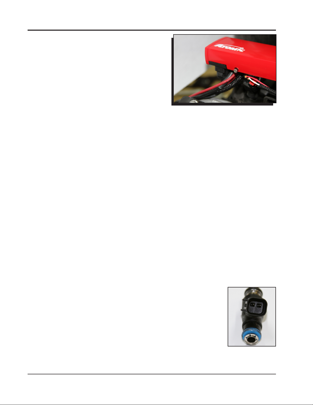
Injectors: The kit supports the factory EV6 style injectors (Figure 14).
Intake Air Temperature (IAT) sensor: The sensor is supplied in the parts bag.
It is recommended to install the sensor in the intake air track before the
throttle body. A ¾” hole is required for the sensor.
Map sensor: The kit supports the original equipment (OE) MAP sensors.
Oil Pressure (Oil) sensor: The kit utilizes the factory oil pressure sensor. There
are different style sensors, but the connector is the same between these
sensors.
Power: The heavy gauge wire supplies 12v to both fuel rails from the power
module.
Figure 14
MSD • WWW.MSDPERFORMANCE.COM • (915) 855-7123 • FAX (915) 857-3344
Page 7

INSTALLATION INSTRUCTIONS 7
Throttle Position (TPS) Sensor: The kit has a connector on each rail for the TPS sensor. It must be
plugged into the driver side rail. The kit only supports a cable driven throttle body at this time
and includes an adapter harness for the TPS sensor used on a cable driven throttle body.
Wide Band O2 Sensor: A wide band O2 sensor is supplied with the kit. The O2 sensor is used by
the ECU to monitor air/fuel ratios (AFR) in the exhaust gases. Adjustments are made by the
ECU in closed loop to maintain (AFR).
MSD • WWW.ATOMICEFI.COM • (915) 855-7123 • FAX (915) 857-3344
Page 8
8 INSTALLATION INSTRUCTIONS
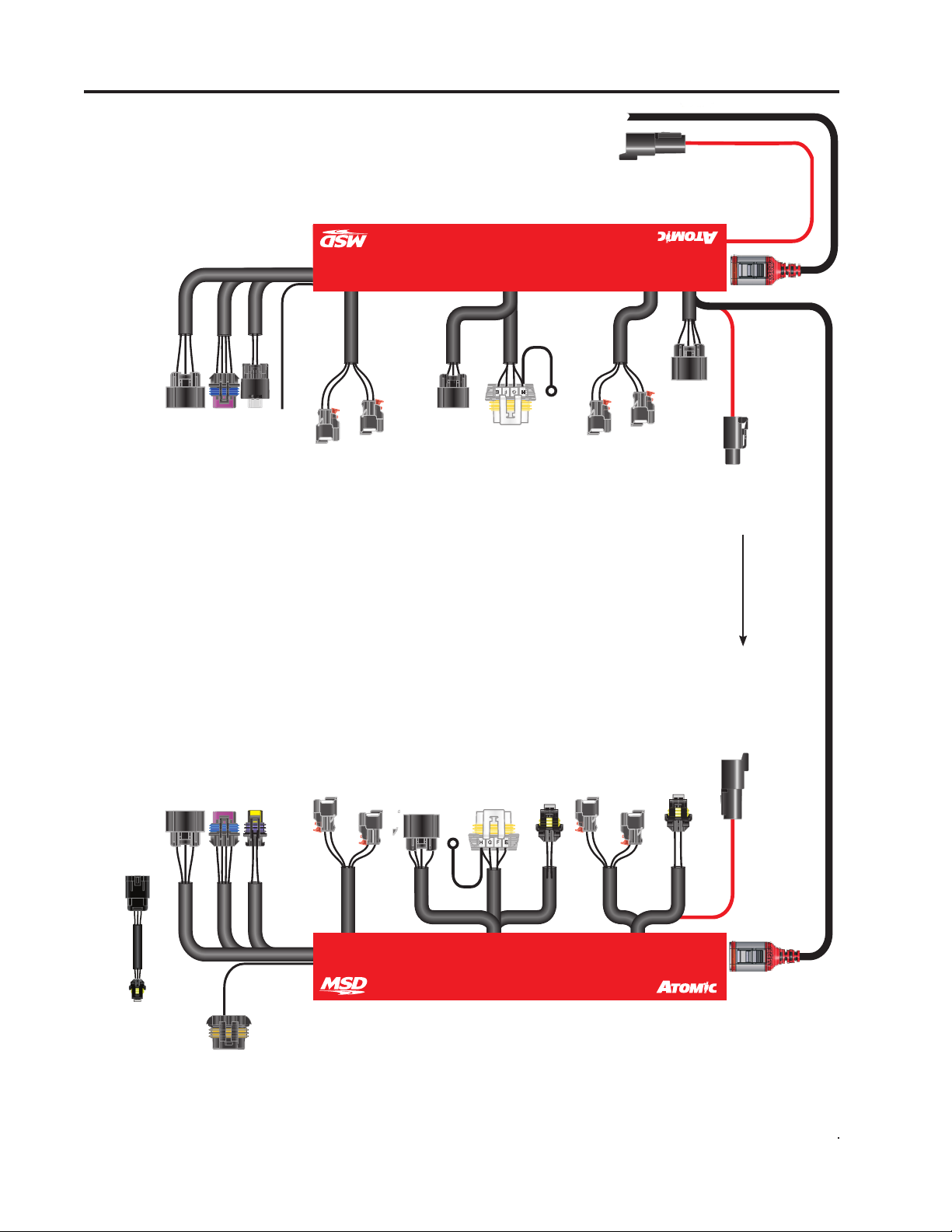
*INJECTORS ADAPTERS
ARE INTERCHANGEABLE.
(EV6 Adapters shown)
NOTE: Do not cross the
injector harnesses when
installing them on the
injectors.
PASSENGER
MODULE
POWER
TO
ETC/
A. Brown
B. Pink
C. Brn/White - Gnd
D. Not Used
V V T
D. Black - Coil 2B
E. Green - TPS1
F. Orange - 5V
G. Violet - TPS2
H. Not Used
(NOT USED
ON LS7)
D LPHI
D LPHI
IAT
IAC2
A. Black - Ground
B. Violet - Signal
A. Orange - Coil 1B
B. Gray - Coil 1A
C. Blue - Coil 2A
CURRENTLY
USED)
(NOT
Orange - AC
INJ2*
1. Signal
2. 12V
INJ4*
1. Signal
2. 12V
MAP
2, 4, 6, 8
A. Orange - 5V
B. Lt Green - Signal
C. Brown - Ground
E. Brown - Ref Gnd
F. White - Coil 6
G. Lt. Blue - Coil 8
H. Pink - 12V
SIDE
FGH
COILS
A. Black - Ground
B. Tan - Coil 2
C. Lt. Green - Coil 4
D. Not Used
Black - GROUND
INJ6*
1. Signal
2. 12V
INJ8*
1. Signal
2. 12V
CRANK
A. Pink - 12V
B. Orange - 5 V
C. Brown - Ground
D. Org/Yel - Signal
Red - POWER Red - POWER
Red - POWER
CAN
A. Brown
B. Pink
C. Brn/White - Gnd
D. Not Used
E. Green - TPS1
F. Orange - 5V
G. Violet - TPS2
H. Not Used
1. Orange - 5V
2. Black - Ground
3. Blue - Signal
TPS ADAPTER
B. Gray - Coil 1A
C. Blue - Coil 2A
D. Black - Coil 2B
ETC/TPS
IAC
C. Not Used
D. Not Used
A. Orange - Coil 1B
A. Black - Ground
B. Yellow - Signal
ECT
A. Not Used
B. Brown - L Term
ALT
1. Signal
2. 12V
INJ1*
1. Signal
2. 12V
INJ3*
F. Green - Coil 3
G. Tan - Coil 1
H. Pink - 12V
A. Pink - 12V
B. Orange - 5V
C. Brown - Ground
D. Brn/Wht - Signal
GROUND
CAM
Black
A. Black - Ground
B. Blue - Coil 7
C. Brn/White - Coil 5
D. Not Used
E. Brown - Ref Ground
1. Black - Ground
2. Orange - 5V
3. Lt Blue - Signal
1, 3, 5, 7
COILS
H
F
G
DRIVER
SIDE
FPS
1. Signal
2. 12V
INJ5*
1. Signal
2. 12V
INJ7*
1. Black - Ground
2. Orange - 5V
3. White - Signal
OIL
2. Yellow - CAN HI
3. Blk/Red - Gnd
4. Black - Gnd
5. Orange - Crank
6. Brown - Cam
7. Blue - Tsync
8. Gray - Shield
CAN
1. Green - CAN LO
Figure 15 Wiring
MSD • WWW.MSDPERFORMANCE.COM • (915) 855-7123 • FAX (915) 857-3344
Page 9

INSTALLATION INSTRUCTIONS 9
POWER MODULE INSTALLATION
The Power Module of the Atomic EFI system handles high
current circuits such as the fuel pump and WBO2. The unit has
two ports for the MSD CAN system as well as a wiring harness.
The CAN ports will provide communication between the Power
Module, the passenger side fuel/ECU rail and the Handheld
Monitor. It is important to select a proper mounting location for
the Power Module. The unit can be mounted in the interior or
the engine compartment as long as it is away from direct heat
sources. It is not recommended to mount the unit in an enclosed
area, such as the glove box. When
a suitable location is found, make sure all wires reach their
connections. Also be sure that the CAN port can be accessed
Figure 16
for use with the Handheld
Monitor. Use the Power Module
®
as a template and mark the
location of the holes. Use a size
#20 drill bit to prepare for the
supplied self tapping screws.
Assemble the sleeves in the
LS
CONTROLLER
MONITOR
CONNECTOR
ONLY
power module (Figure 16).
HANDHELD
POWER MODULE WIR-
MONITOR
ING (FIGURE 17)
Not all of the wires from the
Power Module need to be
connected for proper operation
of the Atomic LS7 kit. Some of
the wires such as the nitrous
input, 2-step rev control, or
electric fan controls only need to
be connected if their functions
are being used. In the chart
labeled Power Module Wiring,
wires marked “REQ” must be
connected for the system to
operate while those marked
FUEL PUMP
GROUND
BATTERY 1*
BATTERY 2*
“OPT” are optional depending
on the features needed. For the
initial installation and start up,
* BATTERY 1 AND 2
MUST BOTH BE
CONNECTED
it is recommended to connect
only the required wires.
Note: The Power Module
uses two heavy gauge wire
connections to the battery. Both
Figure 17 Power Module Wiring Diagram.
leads must be connected in
order for the Power Module and Atomic LS Truck kit to operate correctly.
• ConnecttheCANfromthefuelrailsintothecenterCANportonthePowerModule.
• ConnecttheHandheldMonitortotheCANportontherightsideofthePowerModule.
• Connectthe16-pinGTconnectorharnessincludedinthekit.
• Connectthe4-pinDeutschconnectharnessincludedinthekit.
• ConnectthewidebandO2sensorincludedinthekit.
• Makeallthenecessaryelectricalconnections.
CAN
ONLY
SLED POWER
FAN 1
LAUNCH
NITROUS
SPEED REF
SPEED
TACH
SW 12V
FAN 2
MIL GROUND
IP
RED
VM
YELLOW
H-
BLK/WHT
H+
BLK/RED
IA
GREEN
UN
BLACK
TO PASSENGER
TO PASSENGER
FUEL RAIL
FUEL RAIL
POWER TO
PASSENGER
FUEL RAIL
MSD • WWW.ATOMICEFI.COM • (915) 855-7123 • FAX (915) 857-3344
Page 10

10 INSTALLATION INSTRUCTIONS
Power Module
Pin
1
2
4-Way
3
Deutsch
CONNECTOR
4
A
B
C
D
E
F
G
H
J
CONNECTOR
GT Series 16 Way
K
L
M
N
P
R
S
Color
Red
Black
Orange
Red
Red
Blue
Bro/Wht
Brown
Lt Blue
Gray
Red
Orange
Red
Red
Yellow
Blk/Wht
Blk/Red
Green
Black
Lt Green
Use
REQ
REQ
REQ
REQ
OPT
N/A
OPT
OPT
OPT
OPT
REQ
OPT
REQ
REQ
REQ
REQ
REQ
REQ
REQ
OPT
Function
Battery 1, Connect to Positive Battery terminal. Must be connected.
Ground, Connect to solid, clean engine ground.
Pump, Connect to Fuel Pump Positive terminal.
Battery 2, Connect to Battery Positive terminal. Must be connected.
Fan 1, Supplies ground to activate Fan 1
Reserve for later use.
Nitrous, When supplied with 12 volts, timing will be retarded and the
air/fuel ratio will be corrected to the target nitrous setting.
Speed Ref. (-)
Speed Signal (+)
Tach, Supplies 12V square wave signal
Switched 12V, Connect to ignition switch
Fan 2, Supplies ground to activate Fan 2 at desired temperature.
Supplies power to the Fuel Rail
IP
VM
H-
WBO2
H+
IA
UN
MIL Ground
This wire functions as a Malfunction Indicator
Lamp (MIL). This wire will provide a ground in the
event of a diagnostic code. Connect the (MIL) to
the ground side of a light bulb or LED. Connect
the other side of the light blub or LED to 12v.
FUEL SYSTEM REQUIREMENTS
The Atomic LS fuel injection system requires a high pressure fuel pump system. The fuel system is not
supplied due to the large variety of applications incorporating the LS engine platform. Depending on
your engine combination, the Atomic LS requires a minimum of 58-62 psi to operate. When selecting a
pump, regulator and lines, be sure each component is designed to perform at high pressure. MSD offers
fuel pumps, hose and accessories to complete your installation. Following are some guidelines intended
to help set up a fuel system for your Atomic as well as components available separately from MSD. The
Atomic is capable of operating with a return or returnless style system.
•Whenrunningareturnlessfuelsystem(PulseWidthModulated)thefuelpumpmustbemountedinthe
tank. This will result in quieter operation, a reduction in pump temperature, and a less likely chance of
fuel pump cavitation.
•MSDsupplies-6ANPush-Lockstylettingsforthefuelrails.ThesettingsmustbeusedwithMSD's
high pressure EFI hose.
• Ifmountingthepumpinthetankisnotanoption,installthepumpascloseaspossibletothetank.
Within 2-feet of sending unit is recommended. MSD recommends the Atomic Fuel Pump, PN 2925 or
PN 2926.
•WhenusingaPWMfuelsystem,pulsationsandharmonicscouldcauseunstablefuelpressurethatcan
result in fuel pump cavitation or poor engine performance. For this reason MSD recommends not to
use a hard line for the fuel system in PWM mode.
MSD • WWW.MSDPERFORMANCE.COM • (915) 855-7123 • FAX (915) 857-3344
Page 11

INSTALLATION INSTRUCTIONS 11
, MOUNT
FUEL SYSTEM INSTALLATION
FUEL RAIL
(UNDER COVER)
-6 90° FITTING SUPPLIED
FUEL RAIL
FUEL RAIL
(UNDER COVER)
(UNDER COVER)
NOTE: IF RUNNING A RETURNLESS
FUEL SYSTEM, THE PUMP MUST
BE MOUNTED IN THE TANK.
MSD ADJUSTABLE
REGULATOR
FUEL
FILTER
FUEL TANK
FUEL
PUMP
IT IS RECOMMENDED TO MOUNT
THE FUEL PUMP IN THE TANK
WHENEVER POSSIBLE. IF IT MUST
BE MOUNTED EXTERNALLY
THE PUMP WITHIN 2-FEET OF THE
FUEL TANK SENDING UNIT.
Figure 18.
IN-TANK PUMPS
The MSD Atomic Fuel Pump (not supplied) can be used in the tank however it would require a sock,
or filter element on the pickup side of the pump. It is important to note that the wiring used to run the
pump will need to meet requirements to be submersed in fuel. When wiring an in-tank pump, it is
recommended to use a wire that conforms to SAE specifications J1128 and J378. This wiring features
a Thermoplastic insulated wiring with polyvinyl chloride insulation for protection against gasoline,
oil, and more. In addition, different fuel line will be required internally if the pump is to be mounted
in the tank. Fuel line that meets SAE 30R10 specifications MUST be used. Failure to do so will cause
severe damage to your engine and/or fuel system.
WARNING: Improper installation or use of fuel system components can cause severe damage to
the engine and/or fuel system that will not be covered by the manufacturer’s warranty.
Atomic Fuel Pump, PN 2925: This pump features 3/8” inlet and outlet. The pump will support
approximately 525 hp and is approved for in-tank use (no wiring or in-tank mounting hardware/
pickup element are supplied).
Fuel Pump Kit, PN 2920: This Kit is supplied with MSD’s PWM Fuel Pump, a pre and post-filter, 15-ft
of 3/8 fuel injection line and mounting hardware.
Fuel System Return Kit, PN 2922: If you plan on running a return line with your Atomic LS, this kit
provides another 15-ft of 3/8” injection line, an MSD Regulator and several push-lock fittings.
High Horsepower Fuel Kit, PN 2921: This pump will support the power demands of engines up to
650 horsepower. The pump features 3/8” inlet and outlet and is approved for in-tank use (no
wiring or in-tank mounting hardware/sock are supplied).
FUEL INLET FITTINGS AND CROSS-OVER LINE
LS engines require a cross-over fuel line to route the fuel from one bank to the other. This is typically
done at the front of the engine (Figure 19).
Due to the variety of intake manifolds and
accessories a cross-over line must be made
for each application.
Figure 19 Installing Fuel Hose to the Push-Lock Fittings.
MSD • WWW.ATOMICEFI.COM • (915) 855-7123 • FAX (915) 857-3344
Page 12

12 INSTALLATION INSTRUCTIONS
MSD supplies a length of fuel hose and two 90° -6AN
fittings to prepare a fuel crossover line. The fittings utilize
Push-Lock technology and are designed exclusively for
use with the supplied hose. These fittings do not use
clamps, however it is imperative to follow the installation
instructions.
Proper installation begins with a clean, square cut of
the hose. A hose cutting tool or new razor blade are
recommended. When installing the hose it is important
that the hose is pushed on all the way to the thin beauty
ring (Figure 20). This means the hose should fully overlap
the inboard barb. Too little engagement, as well as overengagement, will result in a compromised connection that
is prone to failure.
1. Determine the length of hose needed. Mark the hose
and cut it using a hose cutter or new razor blade.
There should be minimal disturbance of the outer
jacket, braids and inner liner. The cut plane should be
perpendicular to the hose axis. (Figure 21).
2. Before installing the hose to the fitting, it is important
to anchor the fitting. Proper installation cannot be
achieved by holding the hose and fitting in your hands.
For best results, the hose should be installed with
minimal twisting or pausing.
3. Apply a light coat of oil to the barbs on the fitting and
to the inside of the fuel hose. Use care not to get oil on
the outside of the hose as it will be impossible to get a
firm grip on the hose.
4. With the fitting anchored securely, push the hose over
the barbs. The hose is properly installed when it is flush
with the thin edge of the beauty ring (Figure 22). At this
point, the hose end should have rolled over the inboard
barb.
WARNING: MSD’s Push-Lock fittings are designed for
use with the MSD fuel hose only. Do not use
the MSD fuel hose with other fittings. Do not
use MSD Push-Lock fittings with other fuel
hose. Compatibility issues may cause fuel
leaks. Fuel Inlet Fittings and Cross-Over
Line: LS engines require a cross-over fuel
line to route the fuel from one bank to the
other. This is typically done at the front of
the engine. Due to the variety of intake
manifolds and accessories a cross-over
line must be made for each application.
The supplied MSD Push-Lock AN fittings
are designed only for use with the supplied
fuel hose (Aeroquip AQP FC598). We
do not recommend mixing Push-Lock
style fittings and hoses from different
manufacturers. Doing so may result in
fuel leaks and expose other dangerous
incompatibilities.
Figure 20 Installing Fuel Hose
to the Push-Lock Fittings.
CORRECT CLEAN,
SQUARE CUT
INCORRECT
JAGGED, ROUGH
CUT RESULTS IN
A COMPROMISED
CONNECTION
Figure 21 Severing the Hose Properly.
Properly Installed Push-Lock Fitting
Improperly Installed Push-Lock Fitting
Figure 22 Installed Push-Lock Fitting.
MSD • WWW.MSDPERFORMANCE.COM • (915) 855-7123 • FAX (915) 857-3344
Page 13

INSTALLATION INSTRUCTIONS 13
WIDE BAND OXYGEN SENSOR INSTALLATION
The MSD Atomic EFI system requires a single Wide
02 SENSOR
Band Oxygen Sensor (WBO2) for operation. MSD
suggests that the bung for this sensor be installed
prior to starting any other part of the conversion
process. By having the WBO2 in place first, there is a
reduced chance of the vehicle being immobilized for
an extended time. The bung for the WBO2 provided
POSITION
AT LEAST
10°
by MSD has a plug included so that the vehicle can
be driven between the time of exhaust modification
and installing the rest of the Atomic system, if needed.
EXHAUST
COLLECTOR
The WBO2 can be installed in either exhaust bank. The
sensor connects to the Power Module, so install the
Figure 23 WBO2 Sensor Location.
sensor on the bank closest to where you plan to mount
the Module. The bung should be installed by a qualified exhaust technician and pressure tested.
Proper installation of the oxygen sensor is critical to the performance of the Atomic EFI. Improper
installation could lead to engine damage.
1. Locate the ideal spot to install the WBO2.
a. This location should be 2-4 inches after the exhaust collector. The sensor must be more
than 18 inches forward of the exhaust tip. For applications where short or open headers are
used, install the WBO2 in the primary tube of the rear cylinder at least 8 inches away from
the exhaust port. The Atomic will not work on “Zoomie” style headers.
b. The WBO2 sensor should be at least 10˚ above horizontal to allow condensation runoff.
Without this angle the sensor is significantly more likely to sustain water damage (Figure 23).
c. Never place a WBO2 on the outside of a bend.
d. The WBO2 must be mounted in the exhaust prior to any catalytic converter, if applicable.
2. Drill a 7/8” hole in the exhaust where the WBO2 will go.
3. Weld in the supplied bung. Ensure the weld goes completely around the bung and is air tight.
4. Insert supplied plug in bung. Never run the vehicle with a WBO2 installed but not plugged in to
the harness and powered up; it will damage the sensor.
5. When completing the Atomic EFI installation, remove the plug and insert the WBO2 for use. MSD
suggests using a small amount of anti-seize on the threads.
Note: The Atomic EFI is extremely sensitive to air leaks in the exhaust system. Any air leak between
the engine and the WBO2 will cause the Atomic to have false readings, which can lead to poor
engine performance, misfires, and an inability to properly auto-tune. Extended running of the
Atomic EFI with an exhaust leak can result in detonation and severe engine damage. Improper
installation of the oxygen sensor, and any damage that may result from such an installation,
is not covered by the manufacturer’s warranty.
MSD • WWW.ATOMICEFI.COM • (915) 855-7123 • FAX (915) 857-3344
Page 14

14 INSTALLATION INSTRUCTIONS
WARNING: DO NOT ATTEMPT TO START THE ENGINE. Before turning the ignition key to the ON
position, confirm all fuel line connections are tight and all electrical connections are correct. After
confirming all electrical connections and fuel lines, turn the ignition key to the ON position. Check
every hose and fitting connection for any signs of fuel leaks. The Handheld screen should illuminate
and display the Main Menu.
PROGRAMMING
The Handheld Monitor plugs into the Power Module via the CAN connection. It can be removed once
the initial setup is complete, or can remain connected for use of features such as the dash or digital
gauge displays. The Handheld Monitor features a joystick to scroll through the settings. Scroll up
and down to the setting and push the joy stick to the right to select the options. When the selection
is made, either push in, or go back (push to the left) to save/confirm settings changes.
MAIN MENU
Six selections will come up the Monitor under the Main Menu.
If this is the first time powering up the Atomic LS, select Initial
Setup (Figure 24).
Atomic LS Dash: This selection allows you to view a variety of
engine functions in real time when the engine is running.
Atomic LS Gauges: This setting puts five important values
in gauge form to ease viewing the data. This includes
engine rpm, oil pressure, engine coolant temperature,
speed (when connected), battery voltage, and air/fuel
ratio.
Initial Setup: These are values that are required to start the
engine.
Advanced Setup: Optional settings for features and optimized
drivability settings.
Diagnostics: This screen will help you troubleshoot and
identify potential issues.
Display Setup: Provides adjustments for the appearance of
the monitor screen.
Main Menu
Atomic LS Dash
Atomic LS Gauges
Figure 24 Monitor Main Menu
MSD • WWW.MSDPERFORMANCE.COM • (915) 855-7123 • FAX (915) 857-3344
Page 15

INSTALLATION INSTRUCTIONS 15
INITIAL SETUP PROGRAMMING
Scroll down to Initial Setup and push the joystick to the right.
The following parameters must be programmed.
Engine Type: This value determines the engine platform (Figure
25). There are over 26 engine combinations to select
from. There is also a Custom setting for highly modified
or aftermarket engines. This setting is important as
once an engine type is programmed, other settings will
default to the OEM components that were supplied on
that engine.
For example, if LQ9 is selected, the coil, injector and MAP
sensor will automatically set to the OEM components.
(Different values can also be input if modifications have
been made.)
Custom: In the event a custom built engine is the target engine,
it is recommended to select the closest Engine Type
setting first. This will produce a start-up calibration and
default settings including the volumetric efficiency tables
for that series of engine. From there, go back into each
selection and edit to the engine specifications.
Engine Size: Once the engine type has been selected, the
stock cubic inches will automatically be set. If the engine
has been modified with a different stroke or bore, select
and input the size. The range is from 100-800 cubic
inches (Figure 25).
Camshaft Type: There are three cam selections to choose;
Street/Stock, Mild and Performance. Note that if the
lobe separation angle (LSA) is less than 108°, it is
recommended to input the next larger cam. Cams with
over 250° duration are not recommended for use with
the Atomic LS system (Figure 25).
Handheld Main Menu
Engine Type
Engine Size
CAM
DURATION AT .050"
Street Stock Less than 210°
Mild 211° - 230°
Performance 231°-250°
Coils: Once the engine type is selected, the OEM coil will be
Camshaft Type
automatically loaded in the default calibration file. If
different coils or MSD LS Coils are used, change the
setting to the correct coil type. (Figure 25)
Note: If an engine type is selected, only the compatible coils
will be available in the Coils screen. For example if LQ9
is selected, the GM and MSD compatible numbers will
only be selectable from the menu.
Coils
Figure 25
MSD • WWW.ATOMICEFI.COM • (915) 855-7123 • FAX (915) 857-3344
Page 16

16 INSTALLATION INSTRUCTIONS
Fuel Injector: Once the engine type is selected above, the
OEM style injector will be automatically loaded in the
default calibration file. If a different injector is used,
change the setting to the correct injector. Most LS
based injectors have the part number stamped on
them (Figure 26).
If using different injectors, you may enter the flow rate
in pounds per hour.
MAP Sensor: Once the engine type is selected above, the
OEM MAP Sensor will be automatically selected.
Fuel Injector Type
However, if a different sensor is used the slope and
offset can manually be entered (Figure 26).
Fuel Pump Type: There are three selections for the fuel pump
system. Select the system in use with the Atomic LS7
system (Figure 26).
• Pulse WidthModulated:Thisselectionisusedonly
when running a returnless fuel system with NO
regulator.
• Non-PWMwithRegulator:Thisselectionisusedwhen
running a return style system with a regulator.
Map Sensor
• PWM with Regulator: This selection is used when
running a return style system with a regulator. It will run
the pump at 50% duty cycle at idle producing quieter
pump operation and will increase a duty cycle of 100%
as the throttle and injector load increase.
Note: It is recommended to use Non-PWM with a regulator
when setting fuel pressure as the PWM setting may
decrease fuel pressure slightly at idle.
Idle RPM Target: Select the rpm that the engine should idle
at. The rpm range is adjustable in 25 rpm increments
Fuel Pump Type
(Figure 26).
Note: Running too high of an idle speed in an automatic
transmission equipped vehicle with a stock torque
converter can cause idle issues in gear.
Rev Limit: The rev-limiter is a fuel cut-off type rev-limiter.
Select the rpm range that engine should rev limit. The
range is 3,000 -12,000 rpm and is adjustable in 25
rpm increments. Default for the rev limit is 6,500 rpm
(Figure 26).
Idel RPM Target
Once all of the settings in the Initial Setup menu are selected,
the Atomic has enough information to start and run the engine.
It is recommended to scroll through the advanced settings to
program selections that may be useful after the initial start up
(such as the cooling fan activation temperatures).
Rev Limit
Figure 26
MSD • WWW.MSDPERFORMANCE.COM • (915) 855-7123 • FAX (915) 857-3344
Page 17

INSTALLATION INSTRUCTIONS 17
ADVANCED SETUP
The Advanced Setup features are optional as the Initial Setup
menu provides the Atomic EFI with the values needed to run
the engine. Features in the Advanced Menu are designed to
deliver additional features and advanced tuning functions to
further enhance the drivability and overall performance of the
engine.
Fans: This setting sets the temperatures to activate two electric
fans. Each circuit will be activated by supplying ground
through the Red (Pin A) and Orange (Pin H) wires of
the GT-Series 16 pin harness from the Power Module. A
relay is required for both circuits since those wires are a
low current ground. The fans will activate at the desired
temperature and will remain on until the temperature
falls below 10° of the setting. Settings are 100°-300°F
(Figure 27).
A/F Targets: The Atomic LS provides an option to set an air/
fuel target for Idle, Part Throttle, Wide Open (WOT),
Nitrous and Boost. The Atomic will use its self-learning
technology to adjust the fuel delivery to meet the target
air/fuel ratio. The values are adjusted in 0.1 increments
and range from rich at 10:1 to dead lean at 16:1. The
ideal air/fuel ratio for cruising is called stoichiometric
and is commonly referred as a 14.7:1 air/fuel ratio. (Fig )
Boost: The Atomic will switch to the commanded boost
A/F ratio once the manifold pressure reaches 110Kpa
(approximately 16psia - 32.5in/Hg).
Ignition Timing: The Atomic provides a base timing table for
each engine application. You can also modify these
settings at idle (closed throttle), part throttle, wide
open throttle (WOT), nitrous, and boost. Each setting
is adjustable +/-10°. Note that the values programmed
are set for stock engines using 91 octane fuel. For lower
octane fuels it is recommended to retard the timing 5°
as a starting point. Timing can be retarded up to 20° in
0.1° increments. Note that in order to alter the timing for
nitrous use, the Nitrous Selection in the Advanced menu
MUST be programmed to ENABLE. When the nitrous is
activated by supplying 12 volts to the Brown/White (Pin
C) wire the timing will retard (Figure 27).
TPS Enrichment: To assist in throttle transitions the Atomic
EFI has a feature to increase fuel delivery by a prescribed
percentage any time there is an increase in throttle
position. If needed, make small changes in no more than
5% increments without further testing. Most engines will
find 25% being sufficient. Most applications will accept
15%-35% enrichment. Adjustable from 0-100% in 1%
increments (Figure 27).
Advanced Setup
Fans
A/F Targets
Igniton Timing
TPS Enrichment
Figure 27
MSD • WWW.ATOMICEFI.COM • (915) 855-7123 • FAX (915) 857-3344
Page 18

18 INSTALLATION INSTRUCTIONS
MAP Enrichment: To assist in manifold pressure transitions
the Atomic EFI offers a MAP enrichment feature. This
function adds fuel based on MAP transitions while
moving the throttle. Large cam vehicles with low vacuum
generally required a slightly smaller number while stock/
small camshaft vehicles with a high vacuum may require
more. If needed make small changes of no more than 5%
increments without further testing, 25% is sufficient for
most engines but between 15-35% is normal. Typically,
the higher the vacuum the higher the percentage needed.
MAP Enrichment Setting
Adjustable from 0-100% in 1% increments (Figure 28).
Nitrous: This setting enables the nitrous timing retard in the
Ignition timing and the nitrous AFR in AF Target setting.
The default setting is DISABLED (Figure 28).
Calibrate Speed: If there is speed output on the transmission,
a reference signal can be delivered to the Atomic LS. On
manual transmission equipped vehicles, the Calibrate
Speed option improves drivability when transitioning
from high RPM conditions to an idle (such as comming
off of a hill / between moving and coming to a complete
2-Step RPM Limit
stop). The Power Module has a Brown (Pin D) wire
and a Light Blue (Pin E) wire. These wires connect to
a magnetic pickup monitoring driveshaft speed with a
collar mounted on a yoke. To program the calibration,
drive to 40mph on an open road to maintain speed.
Once at 40mph, select YES on the handheld. This will
calibrate the speed input. This option will also enable a
speedometer reading in the handheld Atomic LS Dash
(Figure 28).
Enable or Disable Nitrous
Note: Use of a minimum four magnet collar is
recommended with this option.
Racepak Dash: This setting allows the Atomic LS Truck kit
to interface with a Racepak dash such an IQ3. Disable
is default. Racepak offers an optional V-net sensor to
connect their dash to the MSD Can-Bus connector
(Figure 28).
Speed Reference Setting
Racepak Dash Option
Figure 28
MSD • WWW.MSDPERFORMANCE.COM • (915) 855-7123 • FAX (915) 857-3344
Page 19

INSTALLATION INSTRUCTIONS 19
Before attempting to start the motor, run through the pre-start check list to ensure a safe and successful
start.
• Double-checkallwiring
• Powerandgroundleadsareconnecteddirectlytothebattery.
• Red(PinG)shouldbeconnectedtoa12vignitionsourcethatishotintheRUNandSTARTpositions
of the key cycle.
• Allwiring,modules,andfuelcomponentsaremountedawayfromheatsourcessuchasexhaust
and pinch points.
• WidebandO2sensorisinstalledandpluggedintothePowerModule
• Therearenoexhaustleaks.
• Thethrottlecableisconnectedandmovesfreelywithnobinding.
• Theinitialprogramminghasbeensetinthehandheldmenu.
• Keyontheignitionafewtimestoprimethefuelpump.Thefuelpressuremayneedtobeadjusted
to 58-60psi. Fuel pressure can be monitored in the Atomic Dash section of the handheld menu.
• Withthefuelsystemunderpressurefromprimingthesystem,checkforleaksorfuelspraying.Do
not attempt to start the engine if fuel leaks are present.
• Monitor EngineRPMinthe AtomicDashinthe handheldunitastheengine iscrankedoverto
ensure the crank sensor is providing an RPM signal.
HANDHELD DISPLAY OPTIONS
Display Setup: The display Setup controls the look
of the handheld unit and the Firmware version.
The Atomic LS can be reset to factory default
in this section as well (Figure 29).
LCD Contrast: Adjust the contrast on the LCD screen
if it is hard to see the display. Contrast is
adjusted using the joystick to go up or down
in five percentage increments.
Backlight Level: The brightness of the screen is
determined by this setting. The Backlight
Level may need to be adjusted depending
on outside light levels. Brightness is adjusted
using the joystick to go up or down in five
percentage increments. (Figure 29).
Display Units: The Atomic can display items in either
English (cubic inches, Fahrenheit) or Metric
(liters, Celsius). Set Atomic Defaults: Use this
feature to reset the Atomic EFI. Selecting “YES” on this screen will take all setting, including
fuel maps, back to the factory defaults. This can be done when installing the Atomic on a
different engine, or for troubleshooting reasons (Figure 29).
Firmware Versions: The Atomic Firmware version can be found in this section (Figure 29).
Figure 29 Monitor Display Selections
MSD • WWW.ATOMICEFI.COM • (915) 855-7123 • FAX (915) 857-3344
Page 20

20 INSTALLATION INSTRUCTIONS
DIAGNOSTICS
There is a self-diagnosing system built into the Atomic EFI. Each
covered parameter can show a status in one of three ways (Fig).
• “OK”:theparameterisfunctioningnormally.
• “ErrorC”:thereiscurrentlyanerroroccurring.
• “ErrorH”:Apreviouserrorthathasbeenresetsinceitdidnot
reoccur within the last ten ignition cycles.
Figure 35
CODE NAME
TPS
MAP
IAT
ECT
BATT
INJ DC
FUEL
PRESSURE
WBO2
WHAT IT MEANS
There is no reading for the Throttle Position Sensor.
There is no reading for the Manifold Absolute Pressure Sensor.
There is no reading for the Inlet Air Temperature Sensor. The ECU will default
to 275°F when shorted or -40°F when
open.
There is no reading for the Engine Coolant Temperature Sensor. he ECU will
default to 275°F when shorted or -40°F
when open.
The Atomic is receiving the wrong voltage. The unit is measuring either less
than 9 volts or greater than 16 volts.
Excessive Injector Duty Cycle
There is no reading for the Fuel Pressure
Sensor.
A. "NOT CONNECTED" indicates that no
sensor is detected.
B. "ERROR" indicates that the sensor
has failed.
PROBABLE CORRECTION(S)
The sensor may be at fault. Check wiring and/or replace sensor.
The sensor maybe at fault. Check wiring and/or replace sensor.
Faulty sensor; loose or no connection. Check wiring and/or replace sensor.
Faulty sensor; loose or no connection. Check wiring and/or replace sensor.
Check the battery connection from the Power Module to the
battery. Ensure that the battery and alternator are working correctly.
Ifyouarerunningareturnlessfuelsystemyourengine'sneeds
mayexceedtheAtomic'smaximumcapabilities.Ifyouarerun-
ning a return system check to see that you are maintaining the
recommended fuel pressure. If you have adequate fuel pres-
suretheengine'sneedsmayexceedinjectorowrate.
Faulty sensor; loose or no connection. Check wiring and/or replace sensor.
A. Check to see that the sensor is securely plugged into the
system. Inspect wiring if it is plugged into the system.
B. The sensor will need to be replaced.
Notethat'warmingup'isnormalduringstart-upfortherst20
seconds.
FP CAV
MAP SELECT
BARO
This code will set if there is an issue with
Fuel Pump Cavitation (similar to vapor
lock). It can only set when running a
returnless fuel system. This may occur
when the commanded fuel pressure
(from the ECU) is different than the fuel
pressure (at the Fuel Pressure Sensor).
ECU compares the MAP reading with
the Baro reading on key up. If these are
different by more than 5kPa, the code
is activated.
The Baro sensor voltage is out of range,
and the ECU has defaulted to the last
known good Baro value.
Check the fuel system and determine that it meets the
requirements to run a returnless (PWM) system. Check the filters,
the sock in the tank, and inspect the lines for any kinks or pinches
that would affect the fuel flow and pressure of the system. If the
code continues, the fuel system may need to be converted to an
in-tank fuel pump and/or regulated (return) fuel system.
Double check your MAP selection and make sure that you
selected the correct P/N of sensor. It could also mean a problem
with the Baro or MAP sensor itself (see above codes).
Turn the ignition off. Wait 10 seconds, and turn the ignition
back on. If the code remains, call customer service. Unless the
vehicle has been through a large change in altitude since the
last ignition on/off cycle (towed somewhere), everything will
function normally.
MSD • WWW.MSDPERFORMANCE.COM • (915) 855-7123 • FAX (915) 857-3344
Page 21

INSTALLATION INSTRUCTIONS 21
CLEAR FLOOD
If a flood condition occurs, turn the key on then press the accelerator to wide-open throttle. This tells
the ECU to turn off the injectors. Crank the engine to clear the flood condition until the engine starts
(release the throttle).
Note: The TPS is self calibrating so the key must be in the ON position prior to pressing the accelerator.
MSD • WWW.ATOMICEFI.COM • (915) 855-7123 • FAX (915) 857-3344
Page 22

22 INSTALLATION INSTRUCTIONS
TECH NOTES
_________________________________________________________________________________________________________________________
_________________________________________________________________________________________________________________________
_________________________________________________________________________________________________________________________
_________________________________________________________________________________________________________________________
_________________________________________________________________________________________________________________________
_________________________________________________________________________________________________________________________
_________________________________________________________________________________________________________________________
_________________________________________________________________________________________________________________________
_________________________________________________________________________________________________________________________
_________________________________________________________________________________________________________________________
_________________________________________________________________________________________________________________________
_________________________________________________________________________________________________________________________
_________________________________________________________________________________________________________________________
_________________________________________________________________________________________________________________________
_________________________________________________________________________________________________________________________
_________________________________________________________________________________________________________________________
_________________________________________________________________________________________________________________________
_________________________________________________________________________________________________________________________
_________________________________________________________________________________________________________________________
_________________________________________________________________________________________________________________________
_________________________________________________________________________________________________________________________
_________________________________________________________________________________________________________________________
_________________________________________________________________________________________________________________________
_________________________________________________________________________________________________________________________
_________________________________________________________________________________________________________________________
_________________________________________________________________________________________________________________________
_________________________________________________________________________________________________________________________
_________________________________________________________________________________________________________________________
_________________________________________________________________________________________________________________________
_________________________________________________________________________________________________________________________
_________________________________________________________________________________________________________________________
_________________________________________________________________________________________________________________________
_________________________________________________________________________________________________________________________
_________________________________________________________________________________________________________________________
_________________________________________________________________________________________________________________________
_________________________________________________________________________________________________________________________
_________________________________________________________________________________________________________________________
_________________________________________________________________________________
MSD • WWW.MSDPERFORMANCE.COM • (915) 855-7123 • FAX (915) 857-3344
Page 23

INSTALLATION INSTRUCTIONS 23
TECH NOTES
_________________________________________________________________________________________________________________________
_________________________________________________________________________________________________________________________
_________________________________________________________________________________________________________________________
_________________________________________________________________________________________________________________________
_________________________________________________________________________________________________________________________
_________________________________________________________________________________________________________________________
_________________________________________________________________________________________________________________________
_________________________________________________________________________________________________________________________
_________________________________________________________________________________________________________________________
_________________________________________________________________________________________________________________________
_________________________________________________________________________________________________________________________
_________________________________________________________________________________________________________________________
_________________________________________________________________________________________________________________________
_________________________________________________________________________________________________________________________
_________________________________________________________________________________________________________________________
_________________________________________________________________________________________________________________________
_________________________________________________________________________________________________________________________
_________________________________________________________________________________________________________________________
_________________________________________________________________________________________________________________________
_________________________________________________________________________________________________________________________
_________________________________________________________________________________________________________________________
_________________________________________________________________________________________________________________________
_________________________________________________________________________________________________________________________
_________________________________________________________________________________________________________________________
_________________________________________________________________________________________________________________________
_________________________________________________________________________________________________________________________
_________________________________________________________________________________________________________________________
_________________________________________________________________________________________________________________________
_________________________________________________________________________________________________________________________
_________________________________________________________________________________________________________________________
_________________________________________________________________________________________________________________________
_________________________________________________________________________________________________________________________
_________________________________________________________________________________________________________________________
_________________________________________________________________________________________________________________________
_________________________________________________________________________________________________________________________
_________________________________________________________________________________________________________________________
_________________________________________________________________________________________________________________________
_________________________________________________________________________________
MSD • WWW.ATOMICEFI.COM • (915) 855-7123 • FAX (915) 857-3344
Page 24

24 INSTALLATION INSTRUCTIONS
TECH NOTES
_________________________________________________________________________________________________________________________
_________________________________________________________________________________________________________________________
_________________________________________________________________________________________________________________________
_________________________________________________________________________________________________________________________
_________________________________________________________________________________________________________________________
_________________________________________________________________________________________________________________________
_________________________________________________________________________________________________________________________
_________________________________________________________________________________________________________________________
_________________________________________________________________________________________________________________________
_________________________________________________________________________________________________________________________
_________________________________________________________________________________________________________________________
_________________________________________________________________________________________________________________________
_________________________________________________________________________________________________________________________
_________________________________________________________________________________________________________________________
_________________________________________________________________________________________________________________________
_________________________________________________________________________________________________________________________
_________________________________________________________________________________________________________________________
_________________________________________________________________________________________________________________________
Service
In case of malfunction, this MSD component will be repaired free of charge according to the terms of the warranty.
When returning MSD components for warranty service, Proof of Purchase must be supplied for verification. After
the warranty period has expired, repair service is based on a minimum and maximum fee.
All returns must have a Return Material Authorization (RMA) number issued to them before
being returned. To obtain an RMA number please contact MSD Customer Service at 1 (888) MSD-7859 or visit
our website at www.msdperformance.com/rma to automatically obtain a number and shipping information.
When returning the unit for repair, leave all wires at the length in which you have them installed. Be sure to include
a detailed account of any problems experienced, and what components and accessories are installed on the vehicle.
The repaired unit will be returned as soon as possible using Ground shipping methods (ground shipping is covered
by warranty). For more information, call MSD at (915) 855-7123. MSD technicians are available from 7:00 a.m. to
5:00 p.m. Monday - Friday (mountain time).
Limited Warranty
M
SD warrants this product to be free from defects in material and workmanship under its intended normal use*,
when properly installed and purchased from an authorized MSD dealer, for a period of one year from the date of
the original purchase. This warranty is void for any products purchased through auction websites. If found to be
defective as mentioned above, it will be repaired or replaced at the option of MSD. Any item that is covered under
this warranty will be returned free of charge using Ground shipping methods.
This shall constitute the sole remedy of the purchaser and the sole liability of MSD. To the extent permitted by
law, the foregoing is exclusive and in lieu of all other warranties or representation whether expressed or implied,
including any implied warranty of merchantability or fitness. In no event shall MSD or its suppliers be liable for special
or consequential damages.
*Intended normal use means that this item is being used as was originally intended and for the original application
as sold by MSD. Any modifications to this item or if it is used on an application other than what MSD markets the
product, the warranty will be void. It is the sole responsibility of the customer to determine that this item will work for
the application they are intending. MSD will accept no liability for custom applications.
MSD • WWW.MSDPERFORMANCE.COM • (915) 855-7123 • FAX (915) 857-3344
© 2013 Autotr onic Contro ls Corporat ion
FRM31778 Created 04/13 Printed in U.S.A.
 Loading...