

Page 1
MSD Pro-Billet Cam Sync Distributor
GREEN: SIGNAL
LED “ON”
RED: 12-14V
BLACK: GROUND
WIRE
DISTRIBUTOR HOUSING
LED “ON”
WIRE FUNCTIONS
LED “OFF”
for approx.
40
0
PICKUP WIRES
MAGNET ON
SPINNING SHAFT -
LED “ON”
DISTRIBUTOR HOUSING
LED “OFF”
PICKUP WIRES
MAGNET ON
SPINNING SHAFT -
LED “OFF”
LED “ON”
(1.5V less than RED)
(less than .3V)
FROM
DISTRIBUTOR
Chevrolet V8, PN 2357
Ford 289/302
Steel Gear, PN 2358; Iron Gear, PN 2359;
Bronze Gear, PN 2360; FE Steel Gear, PN 2363
Parts Included:
1 - Pro-Billet Distributor
1 - Rotor, PN 84211
1 - Distributor Cap, PN 84313
1 - Wire Retainer
WARNING: When installing the MSD, disconnect the battery cables. When disconnecting,
always remove the negative cable first and install it last.
Note: An MSD 6, 7, 8 or 10 Series Ignition is required.
This distributor is equipped with an adjustable Hall-Effect Cam Sync Sensor for fuel injected engines. The Cam Sync can be adjusted to achieve the proper lead time required for the particular
ECU being used.
The distributor also features an adjustable rotor. This allows the rotor phasing to be set properly
and compensate for timing changes.
2 - 1.5" Self Tapping Screws
1 - Tube of Gear Lubricant
1 - O-Ring (Ford) or Gasket (Chevrolet)
2 - O-Rings (Chevrolet)
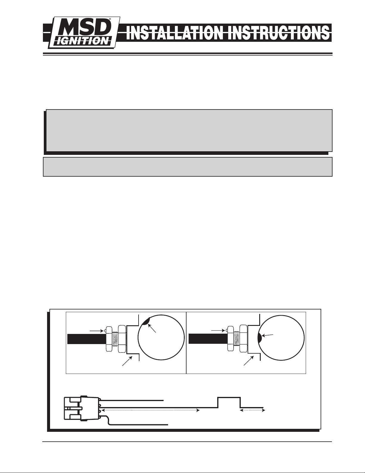
HALL-EFFECT PICKUP
LED OPERATION
The LED is On whenever the magnet is not in front of the pickup. The LED turns Off when the magnet
passes over the center of the pickup (approximately 40°).
SPECIFICATIONS
Accepts 5 – 18 Volts continuous
Output: Within 1.5 volt on the red wire and .3 volt above ground.
Protected from reverse polarity, short circuit and over voltage.
M S D I G N I T I O N • w ww . ms d ig n it i on . co m • (91 5) 8 5 7- 52 00 • F AX ( 915 ) 85 7- 33 4 4
Figure 1 Installing the Hall-Effect Pickup.
Page 2
2
CYLINDER #1
MARK
DISTRIBUTOR CAP
TERMINAL
ROTOR TIP
FULL ADVANCE
ROTATION
NO ADVANCE
INSTALLATION INSTRUCTIONS
INSTALLING THE DISTRIBUTOR
1. Position the engine at your desired timing.
Remove the existing distributor cap without
disconnecting any of the spark plug wires.
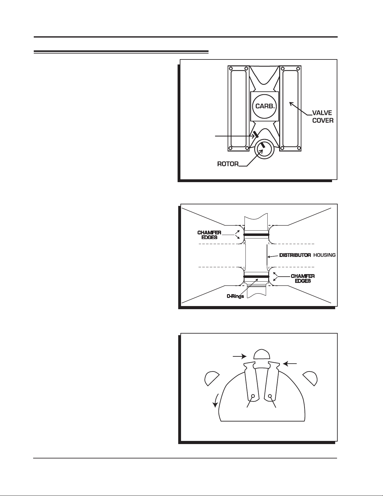
2. Install the O-ring and apply a liberal amount of
the supplied lubricant to the distributor gear.
CHEVY: Install the gasket and apply a liberal
amount of the supplied lubricant to the gear.
(The supplied O-rings can only be used if the
block has been modified as shown in Figure
3.)
3. Install the distributor making sure that the rotor
comes to rest pointing at what will be the
number one cylinder. If the distributor will not fully
seat with the rotor pointing to the marked position,
you may need to rotate the oil pump shaft until
the rotor lines up and the distributor fully seats.
4. Position and tighten the hold down clamp onto
the distributor.
5. Install the distributor cap and spark plug wires
one at a time to ensure correct location.
6. A wire retainer is supplied to secure the wires
in place. Align the mounting bosses and use
the supplied 1.5" self tapping Phillips screws to
hold the retainer in place.
Figure 2 Marking the Rotor Location.
SETTING THE CAM SYNC PICKUP
The Hall-Effect Pickup is designed to provide an
aftermarket ECU with a sync signal. This signal
must be advanced more than the ignition trigger signal. The amount of advance or lead time
depends on the EFI system being used. Always
check with the EFI manufacturer to determine
the advance required for the cam sync.
For example: An ECU requires 10° of advance.
Your engine will be running total timing of 36°.
Position the number one cylinder at 46° and
align the pickup.
1. Once the distributor is locked in place at your
2. With power going to the Hall-Effect pickup,
3. Lock the pickup sync in position.
M S D I G N I T I O N • w ww . ms d ig n it i on . co m • (91 5) 8 5 7- 52 00 • F AX ( 915 ) 85 7- 33 4 4
desired total timing, rotate the engine until
the number one cylinder is positioned at the
required cam sync (If 10° of sync is required
with the engine at 36°, position the engine at
46°).
adjust the pickup until the light turns off (the
output will be higher). This will be the 10° of
advance for the ECU. It is important to rotate
the pickup clockwise until the light turns on, to
find the edge of the magnet. Then rotate the
pickup CCW just until the light turns off.
Figure 3 Modified Block for use with O-Rings.
CCW ROTATION
Figure 4 Rotor Phasing.
Page 3

I
TO
ECU
VIOLET/
BLACK (-)
ORANGE/
BLACK (+)
VIOLET (+)
GREEN (-)
PN 8860
(NOT
SUPPLIED)
INSERT SCREWDRIVER
AND ROTATE TO ADJUST
PHASING
10 INCREMENTS
NSTALLATION INSTRUCTIONS 3
ROTOR PHASING
Rotor Phasing is defined as the alignment between the rotor tip and the distributor cap terminal when
the spark occurs (Figure 4). This position can be very important to your engine's performance. If the
alignment is incorrect, the spark will jump to the next closest terminal or another ground resulting in
a misfire and loss of power.
Since the timing is going to be controlled electronically, it is important to position the rotor phasing at,
or near the total timing (most advanced). Some race applications with timing retards due to nitrous
or boost should split the difference of the retard amount when setting the rotor phasing.
ADJUSTMENTS
The PN 84211 Rotor provides 20° of adjustment
(at the crank). Adjustments are easy by
loosening the rotor screw and using a flatblade
screwdriver to clock to rotor top (Figure 5).
Figure 5 Adjusting the Rotor.
WARNING: High voltage is present on the coil terminals. Do not touch the terminals or coil tower
when the engine is cranking or running.
Figure 6 Wiring to an MSD 6-Series Ignition Control.
M S D I G N I T I O N • w ww . ms d ig n it i on . co m • (91 5) 8 5 7- 52 00 • F AX ( 915 ) 85 7- 33 4 4
Page 4

Figure 7 Wiring to an MSD 7-Series Ignition Control.
TO
ECU
ORANGE/
BLACK (+)
VIOLET (+)
GREEN (-)
TO
ECU
(NOT
SUPPLIED)
Service
In case of malfunction, this MSD component will be repaired free of charge according to the terms of the warranty.
When returning MSD components for warranty service, Proof of Purchase must be supplied for verification. After
the warranty period has expired, repair service is based on a minimum and maximum fee.
All returns must have a Return Material Authorization (RMA) number issued to them before
being returned. To obtain an RMA number please contact MSD Customer Service at 1 (888) MSD-7859 or
visit our website at www.msdignition.com/rma to automatically obtain a number and shipping information.
When returning the unit for repair, leave all wires at the length in which you have them installed. Be sure to include
a detailed account of any problems experienced, and what components and accessories are installed on the vehicle.
The repaired unit will be returned as soon as possible using Ground shipping methods (ground shipping is covered
by warranty). For more information, call MSD Ignition at (915) 855-7123. MSD technicians are available from 7:00
a.m. to 5:00 p.m. Monday - Friday (mountain time).
Limited Warranty
M
SD IGNITION warrants this product to be free from defects in material and workmanship under its intended normal
use*, when properly installed and purchased from an authorized MSD dealer, for a period of one year from the date
of the original purchase. This warranty is void for any products purchased through auction websites. If found to be
defective as mentioned above, it will be repaired or replaced at the option of MSD Ignition. Any item that is covered
under this warranty will be returned free of charge using Ground shipping methods.
This shall constitute the sole remedy of the purchaser and the sole liability of MSD Ignition. To the extent permitted
by law, the foregoing is exclusive and in lieu of all other warranties or representation whether expressed or implied,
including any implied warranty of merchantability or fitness. In no event shall MSD Ignition or its suppliers be liable
for special or consequential damages.
*Intended normal use means that this item is being used as was originally intended and for the original application
as sold by MSD Ignition. Any modifications to this item or if it is used on an application other than what MSD Ignition
markets the product, the warranty will be void. It is the sole responsibility of the customer to determine that this item
will work for the application they are intending. MSD Ignition will accept no liability for custom applications.
M S D I G N I T I O N • w ww . ms d ig n it i on . co m • (91 5) 8 5 7- 52 00 • F AX ( 915 ) 85 7- 33 4 4
© 2009 Aut otronic C ontrols Co rporatio n
FRM29706 Created 07/09 Printed in U.S.A.
 Loading...