

Page 1
MSD Programmable Fuel Booster
USB PORT
ALERT LED
ORANGE
CUT
FACTORY 12 VOLTS
FROM INERTIA SWITCH
RED
1/8” DIAMETER VACUUM
HOSE TO INTAKE MANIFOLD
RED
BLACK
FUEL PUMP +
INDICATES CONNECTION
X
PN 2351
Parts Included:
1 - Programmable Fuel Booster, PN 2351 1 - Software CD 1 - Parts Bag
1 - Harness 1 - USB Cable
The Programmable Fuel Pump Booster will increase the voltage to the fuel pump in proportion to manifold
boost pressure. The maximum voltage output is 22. The minimum output will be the battery voltage.
Note: It is recommended to have the Service Manual for your vehicle to identify the original wiring and fuel
pump relay.
RATING: Continuous Power: 275 Watt, Peak Power: 375 Watt (one minute)
INSTALLATION
The MSD Fuel Pump Booster must be wired inline with the factory fuel pump relay. The factory has safety
features built in, such as an inertia switch and high pressure shut-off which must be retained.
The MSD Fuel Pump Booster can be mounted in any position and is completely potted with a polyurethane
compound for vibration resistance. Keep the unit away from direct engine heat sources and make sure all
of the wiring reaches their connections. Also, allow access to the USB port.
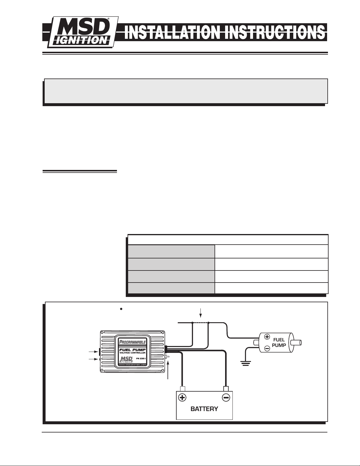
Use the unit as a template and mark the mounting holes. Remove the unit and drill the holes using a 3/16"
bit. Mount the unit with the
supplied screws. With the
unit mounted, route the wiring
to their connections. Also
connect the boost pressure
line to the booster and intake
manifold (Figure 1).
ORANGE (18-GAUGE, long)
RED (12-GAUGE, long)
RED (12-GAUGE, short)
WIRING
OEM Fuel Pump Power (12V)
Pump (+) Positive lead to Fuel Pump
Battery (+) 12V
BLACK (12-GAUGE, short)
M S D I G N I T I O N • ww w. msd ig ni tio n. co m • ( 9 15 ) 8 57 -5 20 0 • FA X (9 15) 85 7 -3 34 4
Figure 1 Recommended Wiring, General Application.
Battery (-) Ground
Page 2
2
LED
The LED will blink fault codes to alert the following
conditions. See charts.
LED ALERTS
ON
OFF
Normal Operation / No Fault
USB Power with No Fault
MSDVIEW SOFTWARE INSTALLATION
In order to install and run the MSDView software,
the following m ini mum requiremen ts are
recommended:
• Microsoft Windows XP/Vista
• Keyboard and Mouse or some other compatible
pointing device.
• Video adapter and monitor (800 X 600) or higher
resolution.
• Available USB port.
• .NET 2.0 or higher.
• Internet access.
INSTALLATION INSTRUCTIONS
BLINKING TWO DIGIT FAULT CODES
12
13
14
21
22
23
24
31
Over Current (25 A)
Open Load (.5 A)
Over Temperature (135° C)
Under Voltage (10V)
Over Voltage (17V)
Map Sensor Out of Range
Untested
Over Voltage - On output
Important: Exit all programs before installing the
MSDView software.
Note: Internet Access is required to install the MSD
View software.
1. Insert the MSD CD into your PC. The software will
automatically begin the installation feature. If the
'Autorun' feature is disabled on your PC, go to:
Start and select Run, Select your CD Drive, and
click on the Setup exe file. The MSDView wizard
will walk you through the setup.
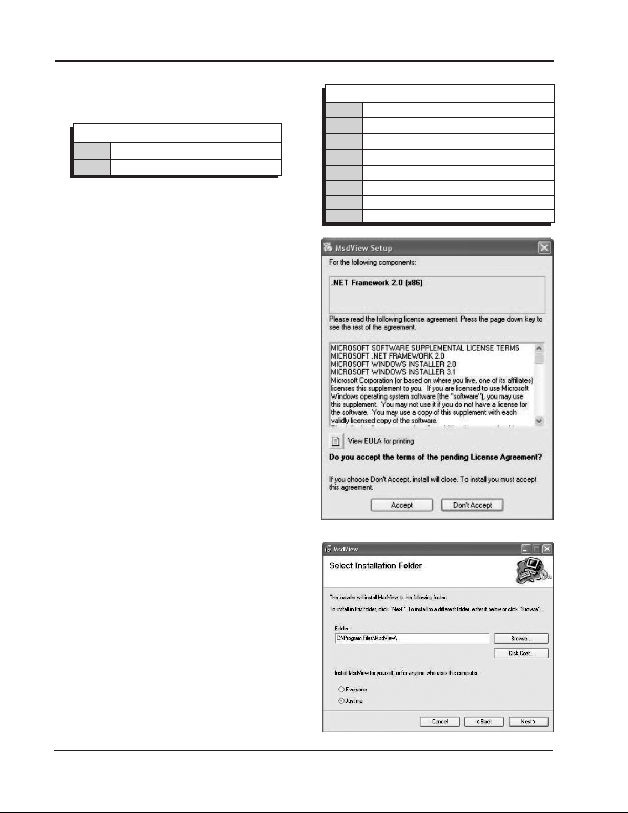
Note: If the .net framework is not installed on your
PC, the MSDView software will prompt the
download and setup. Click Accept to begin the
udpate and follow the steps (Figure 2).
2. You will need to answer several questions such
as a default location, the available disk space
and permissions (Figure 3). The MSDView will
also place a shortcut on your desktop. Once the
installation is complete, select Close to finish the
installation.
Figure 2 .NET Framework Install.
Figure 3 Select Install Folder.
M S D I G N I T I O N • ww w. msd ig ni tio n. co m • ( 9 15 ) 8 57 -5 20 0 • FA X (9 15) 85 7 -3 34 4
Page 3

I
NSTALLATION INSTRUCTIONS 3
TUNING
It is recommended to have a fuel pressure gauge when
testing and tuning with the Programmable Fuel Pump
Booster. The fuel pressure should hold steady under full
boost. Use your boost pressure as a starting reference
point. Use the MSDView software to make the needed
adjustments for optimum performance. The following
pages explain how to load and use the MSD Software
(Figure 4).
In the example in Figure 4, as the MAP reading increases
from 14.5 p.s.i. the pump voltage will increase.
FIRST TIME PRODUCT CONNECTION
The first time the MSD is connected to your PC, a driver
will need to be installed on your PC.
1. Connect the supplied USB harness to the PC and
the MSD. The Found New Hardware Wizard window
will open and walk you through the driver installation
steps (Figure 5).
2. The Wizard will detect the Comm Port and install the
required files. This may take a few moments.
3. The Hardware installation window will stop the setup
to alert you about the installation. Click Continue
Anyway and then Finish to complete the installation
(Figure 6).
Figure 4 Sample Plot.
Figure 5 Hardware Wizard.
Figure 6 Windows Alert.
M S D I G N I T I O N • ww w. msd ig ni tio n. co m • ( 9 15 ) 8 57 -5 20 0 • FA X (9 15) 85 7 -3 34 4
Page 4

USING THE MSDVIEW SOFTWARE
With the MSD connected, open the software by clicking
the icon on your desktop. The screen will prompt for the
MSD product part number (PN 2351) to be selected.
The MSD software is a Graphical User Interface (GUI)
design that incorporates the familiar Windows style
operating environment. There are three tabs that you
can select; Monitor, Settings and Plots.
Monitor: The Monitor Tab allows you to view gauges
for real time readings of the voltage and amps
(Figure 7).
Plots: This tab will display the Trace editor, the Plot
value input and widow (Figure 8).
GAUGE
SELECTOR
Figure 7 Gauge Selector Box.
TRACE
PLOT WINDOW
EDITOR
PLOT VALUE
INPUT
Figure 8.
Service
In case of malfunction, this MSD component will be repaired free of charge according to the terms of the warranty. When
returning MSD components for warranty service, Proof of Purchase must be supplied for verification. After the warranty period
has expired, repair service is based on a minimum and maximum fee.
All ret ur ns m ust ha ve a R et urn Mater ia l Au tho ri zat io n (R MA) nu mbe r issue d t o t he m
before being returned. To obtain an RMA number please contact MSD Customer Service at 1 (888) MSD-7859 or
visit our website at www.msd ignition.com/rma to automa tically obtain a number and shipping information.
When returning the unit for repair, leave all wires at the length in which you have them installed. Be sure to include a detailed
account of any problems experienced, and what components and accessories are installed on the vehicle. The repaired unit will be
returned as soon as possible using Ground shipping methods (ground shipping is covered by warranty). For more information, call
MSD Ignition at (915) 855-7123. MSD technicians are available from 7:00 a.m. to 6:00 p.m. Monday - Friday (mountain time).
Limited Warranty
M
SD IGNITION warrants this product to be free from defects in material and workmanship under its intended normal use*, when properly
installed and purchased from an authorized MSD dealer, for a period of one year from the date of the original purchase. This warranty is
void for any products purchased through auction websites. If found to be defective as mentioned above, it will be repaired or replaced at the
option of MSD Ignition. Any item that is covered under this warranty will be returned free of charge using Ground shipping methods.
This shall constitute the sole remedy of the purchaser and the sole liability of MSD Ignition. To the extent permitted by law, the foregoing is
exclusive and in lieu of all other warranties or representation whether expressed or implied, including any implied warranty of merchantability
or fitness. In no event shall MSD Ignition or its suppliers be liable for special or consequential damages.
*Intended normal use means that this item is being used as was originally intended and for the original application as sold by MSD
Ignition. Any modifications to this item or if it is used on an application other than what MSD Ignition markets the product, the warranty
will be void. It is the sole responsibility of the customer to determine that this item will work for the application they are intending. MSD
Ignition will accept no liability for custom applications.
M S D I G N I T I O N • ww w. msd ig ni tio n. co m • ( 9 15 ) 8 57 -5 20 0 • FA X (9 15) 85 7 -3 34 4
© 2009 Aut otronic Con trols Corpo ration
FRM29438 Created 03/09 Printed in U.S.A.
 Loading...