


Batdude’s Guide
for the
XTS 3000 - XTS 5000
and Astro Digital Saber
3 September 2006
Revised 3 November 2006
As I sat down today to install a NTN8255 DES-OFB module into an XTS 3000 portable
radio, I thought some of you would appreciate an informal walkthrough of the tips to
disassemble the radio and get it back together again without any damage. I can’t count
how many times I’ve seen radios in the used market that have case damage due to
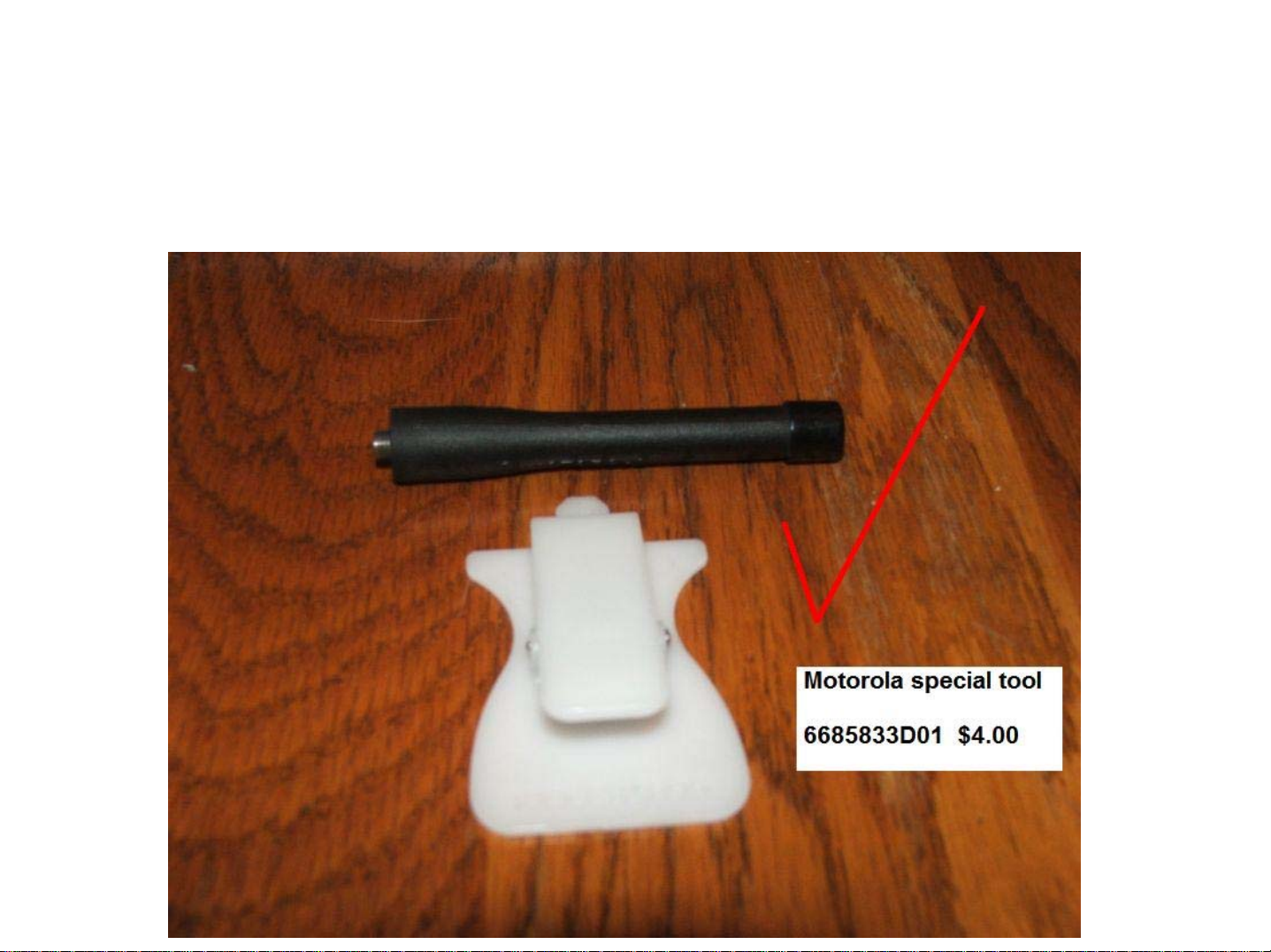
improper disassembly. The key to the entire process is this:
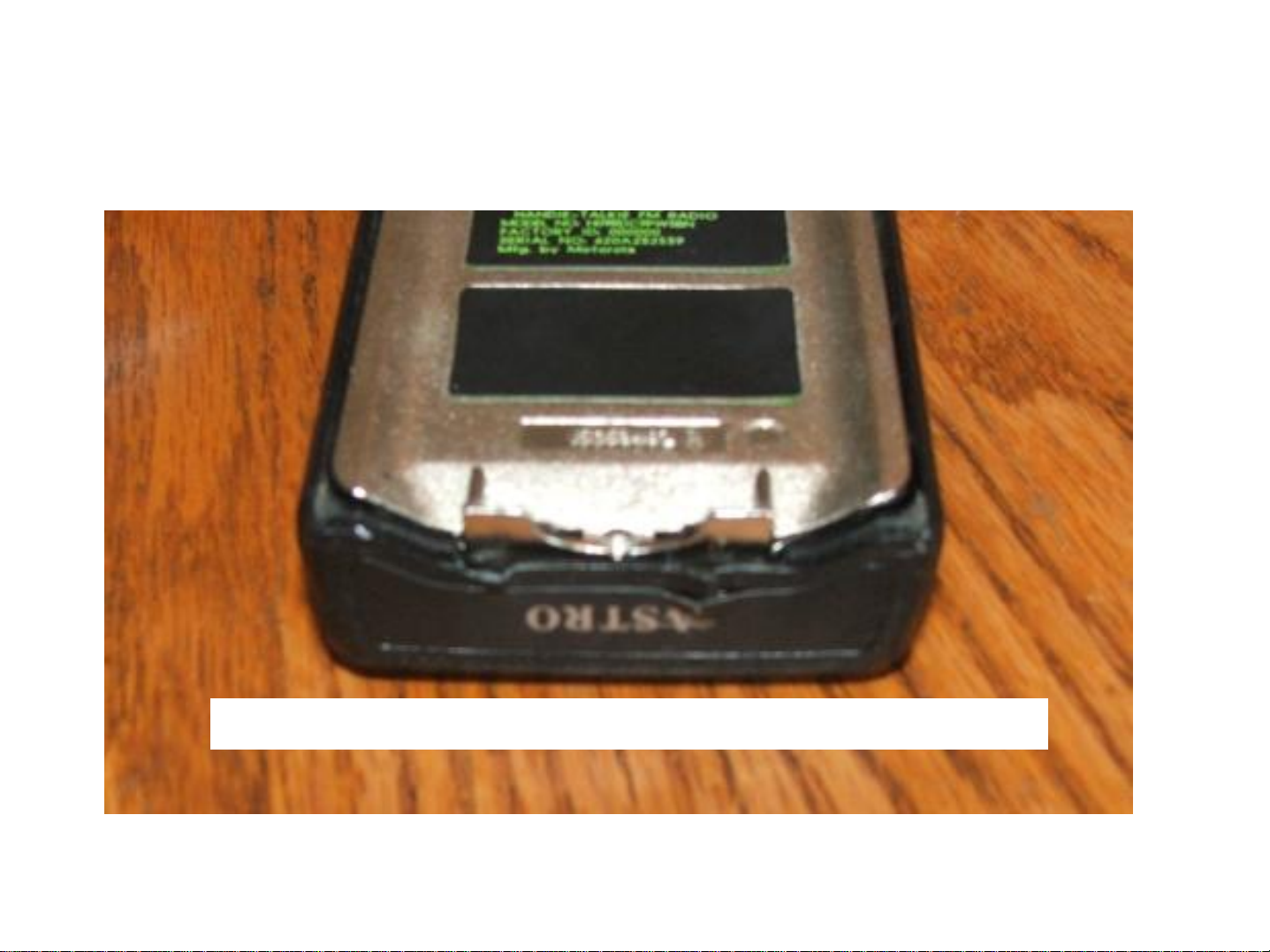
Without this tool, I can guarantee that you will either split the end of the case
plastic, as shown in the below picture, or gouge/destroy the protective o-ring.
This is an actual radio that I purchased at dayton….
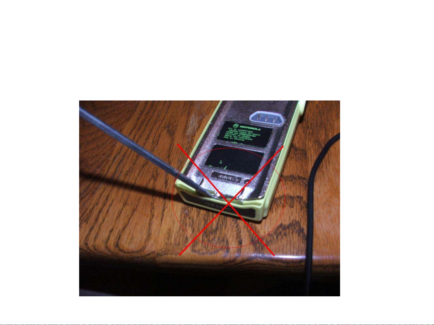
Of course, I’ll show you this, just because I
think it’s indicative of how about 80% of the
people out there open up their radios:
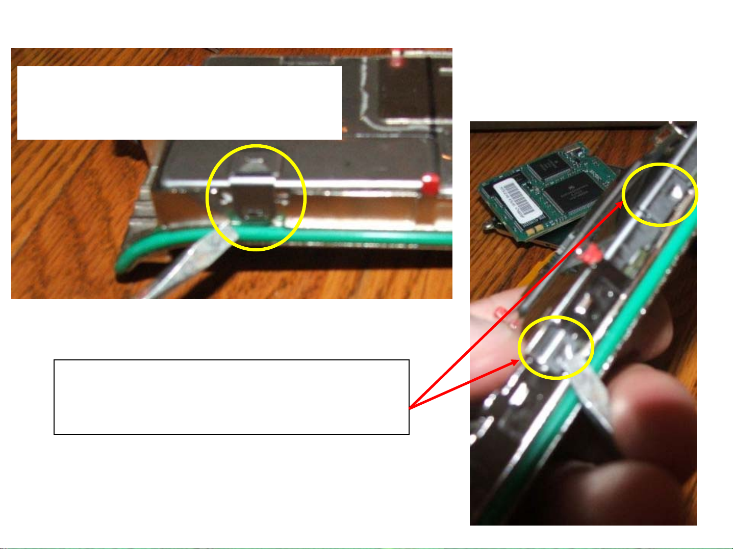
Okay, you have finally ordered your handy-dandy white opener tool, Motorola part
number 6685833D01 (cost is about $4.00) and you’re ready to crack the case. I
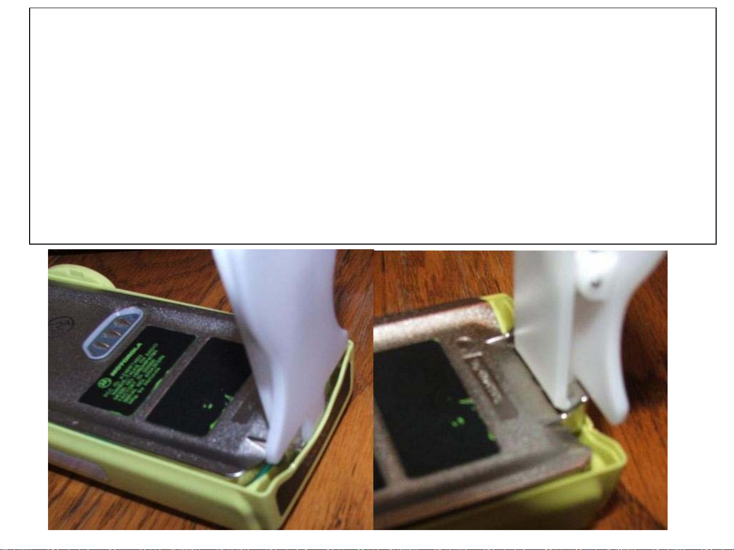
can give you the rhetoric about ESD safety now – obviously what you are seeing
here is on the border of ESD-unsafe. However, I’m not sitting here rubbing my cat
while my feet are on the carpet either. This procedure should (of course) be
conducted at an ESD approved workbench while wearing a wrist strap. Note how
the hinge of the tool “captures” the frame.
MAKE SURE THE ANTENNA HAS BEEN REMOVED
BEFORE DOING THIS!
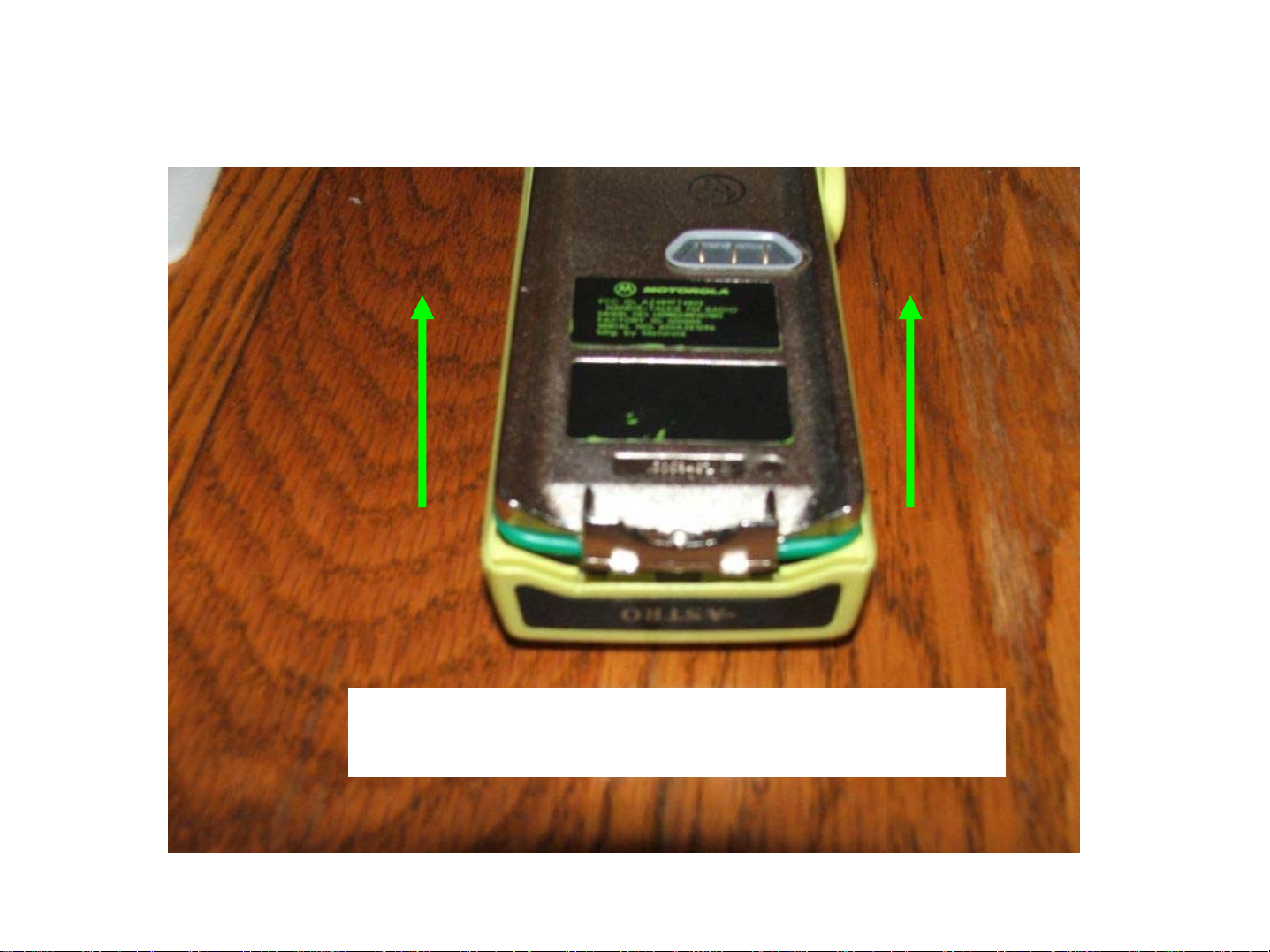
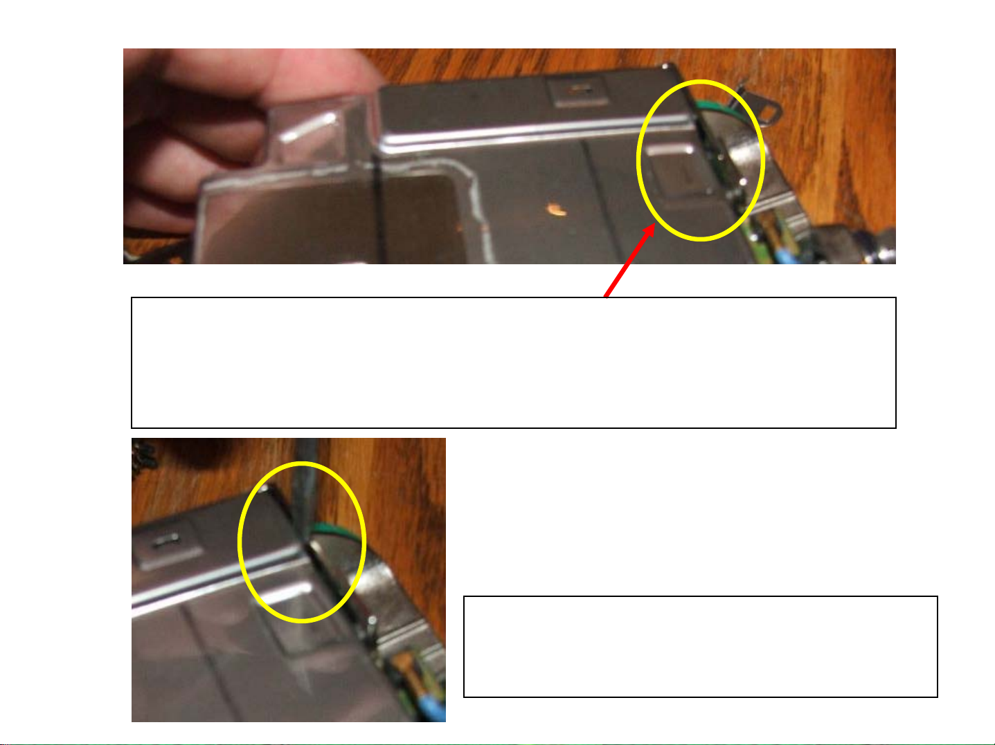
After you get the front shield separated from the chassis, you’ll have the radio
disassembled to this point (note the o-ring is intact and undamaged):
Gently wiggle the chassis free and lift
upward and away from the front shield
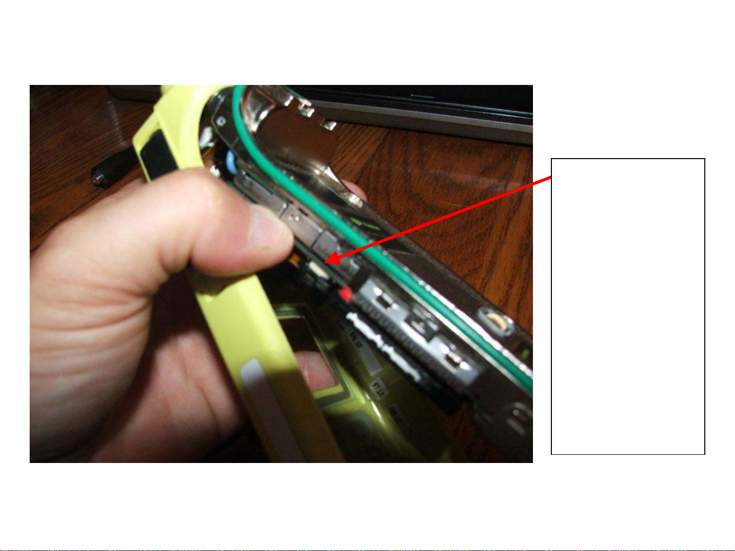
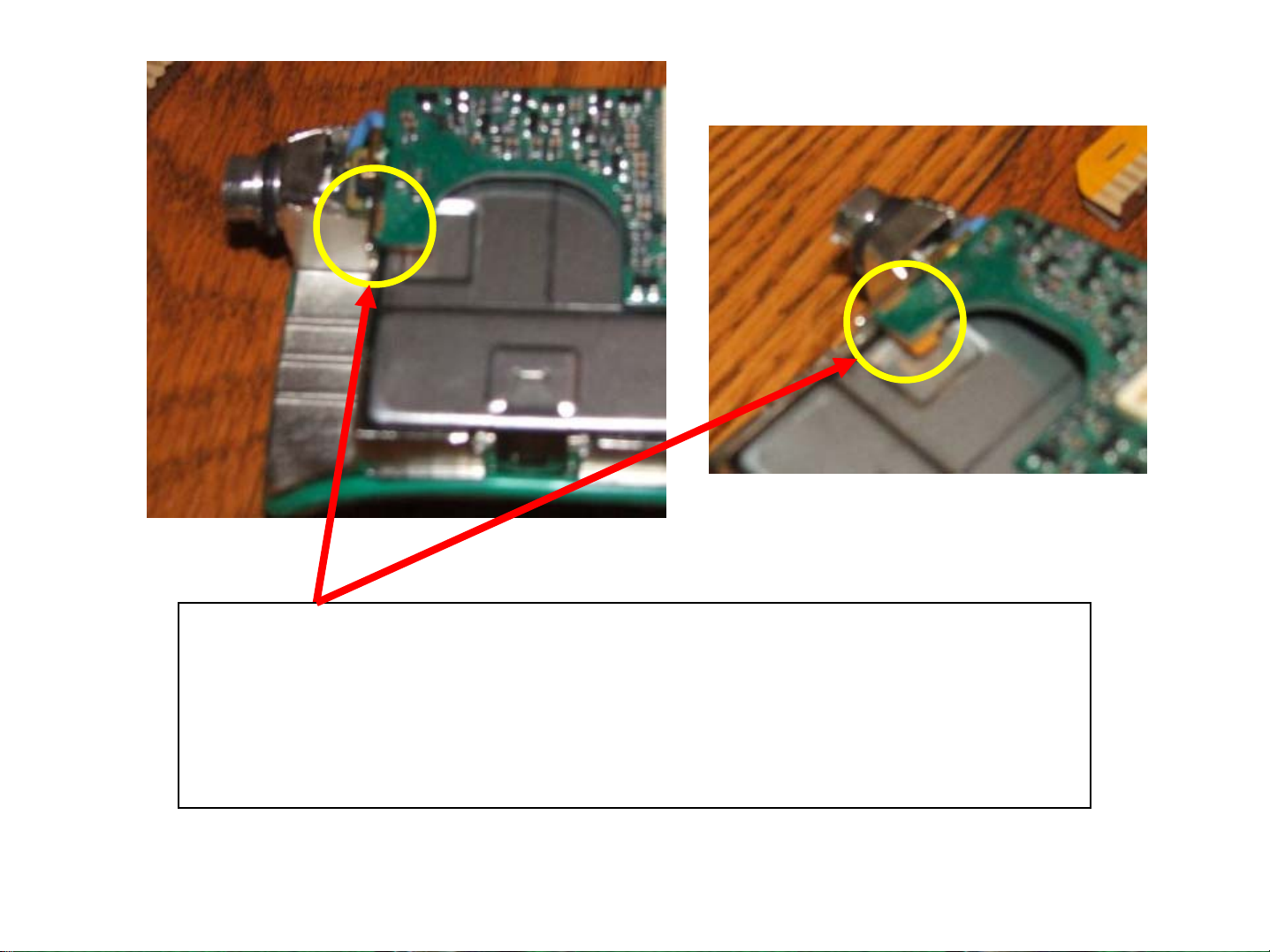
Separating the front shield flex from the chassis can be tricky, but you’ll get
the hang of it – you can use your thumb to pop the flex connector off:
The white part
here is the
connector, the
black is the
plastic flex
support – very
gently pry
downward on
the black
support and the
connector will
unmate with little
or no effort.
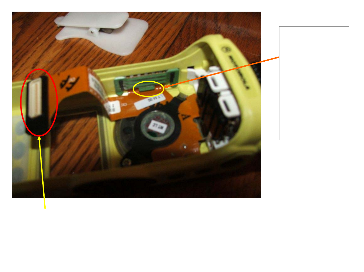
Notice the lip
at the bottom
of this retainer.
This is a
modification
that is required
to prevent
wear on the
flex. See the
next slide.
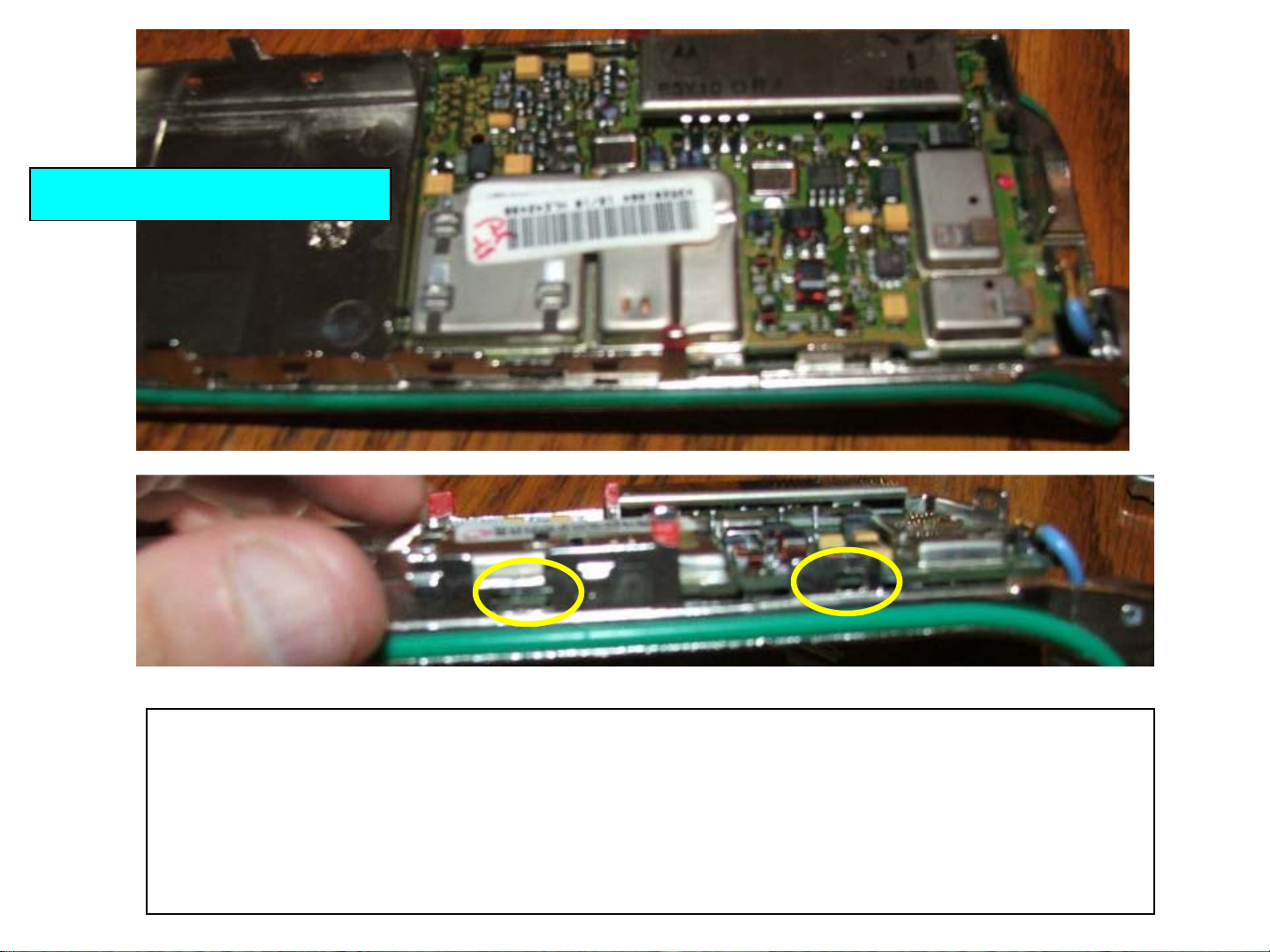
Two things in this picture – one is the connector type – this is a “B” series
connector (notice how wide it is with the male plug in the center). The second
item is the green universal connector plug retainer.
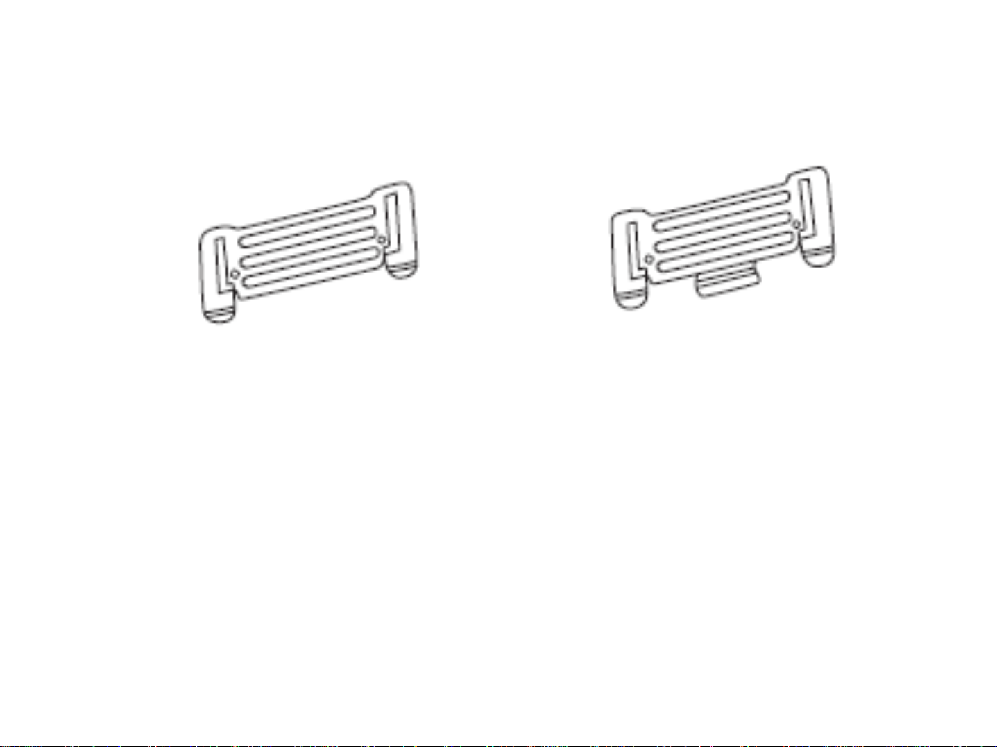
Universal Connector Retainer
Old style on the left, new on the
right. Motorola kit 4205582Z07 was a
retrofit for the old style. You will have to
call parts ID as this doesn’t appear to be
a valid part number anymore…
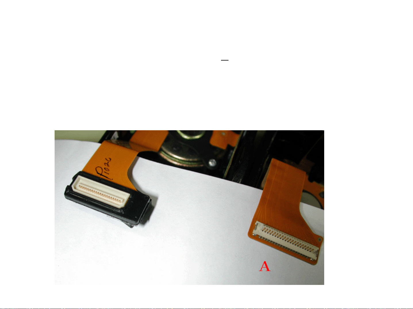
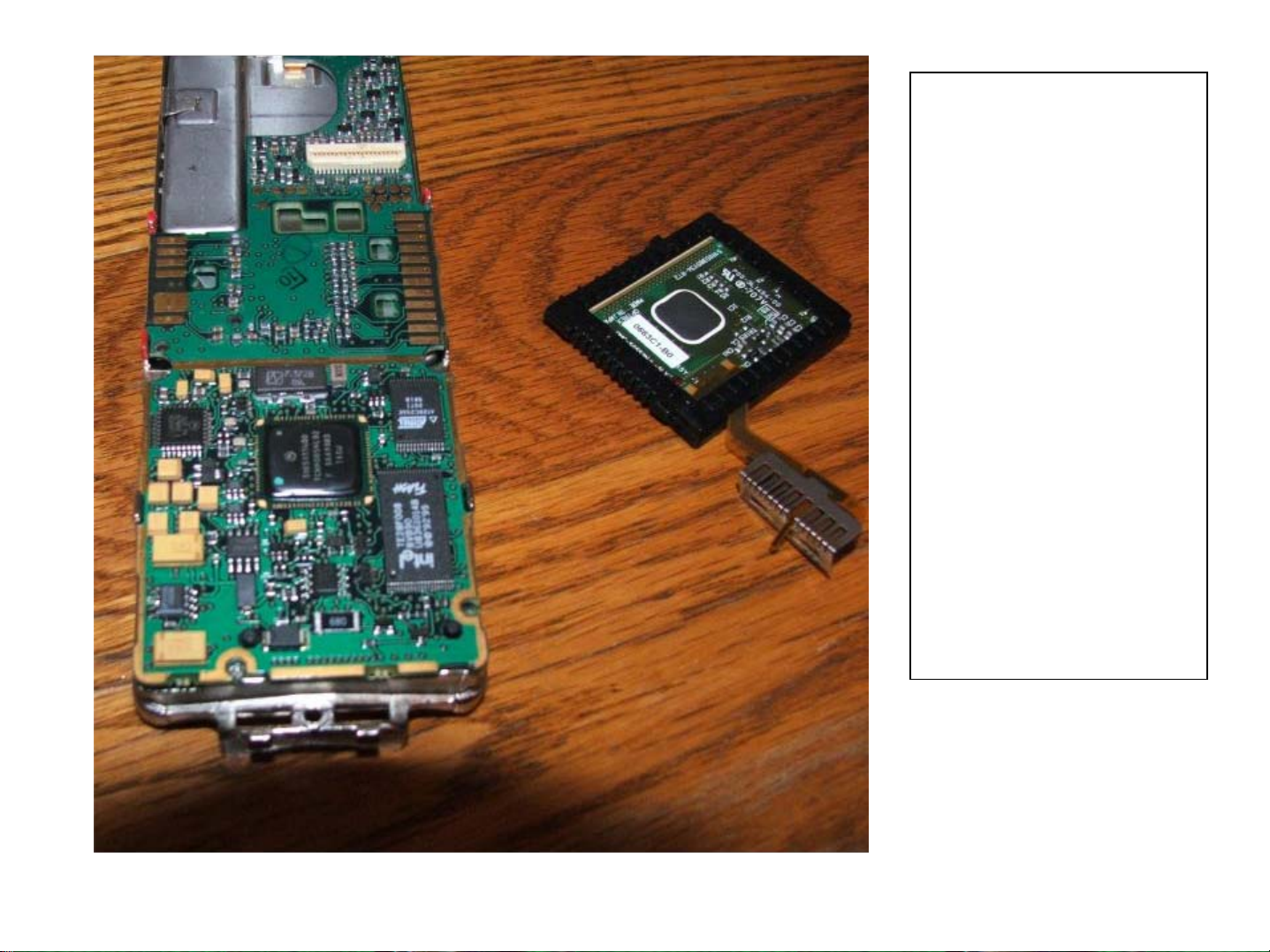
A Series vs. B Series Housings
“A” Series radios (I.e. H09RDH9PW7AN) use a different controller
board (NCN6128) that has a different plug on it for connecting the
front housing. This is CRUCIAL when ordering replacement parts
for your radio! In the below picture, the “B” series is on the LEFT.
Ok, back on track….
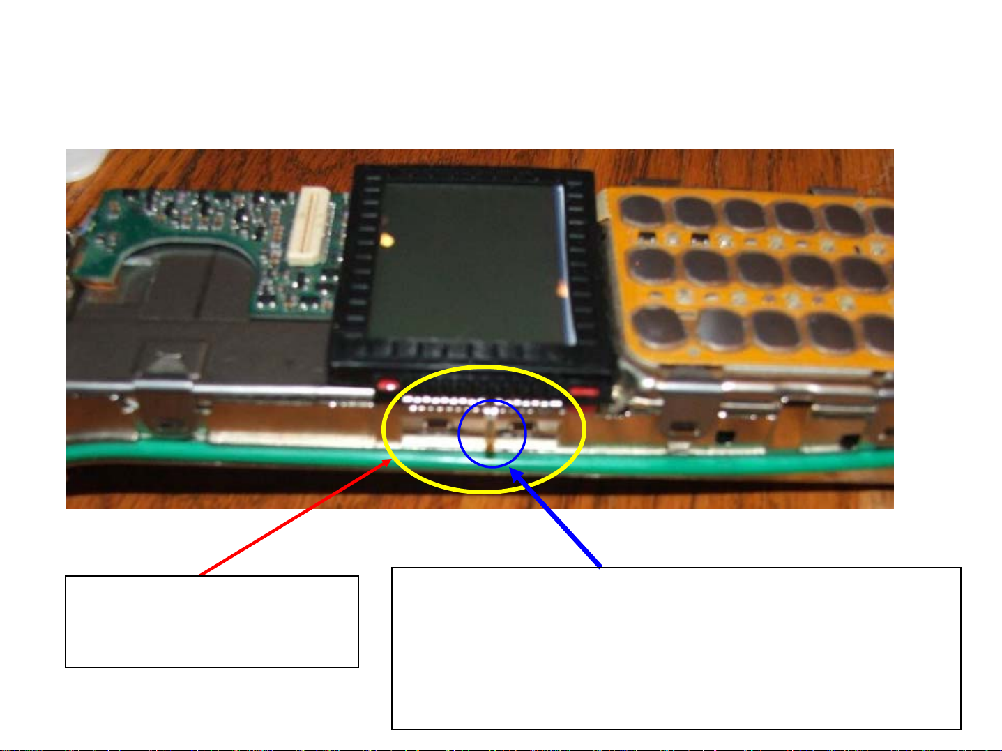
In the below picture, you see the radio with the front shield completely removed.
LCD Flex retainer bracket
– has two snaps that must
be pried upward to remove
One of the most common assembly errors is
right here. This brown “finger” is part of the flex
for the LCD. There is a slot in the retainer to
allow this finger to stick out and be compressed
against the frame during re-assembly.
There is a
cutout in
the
Keypad
shield that
is for the
rubber “tit”
on the
LCD flex –
make sure
it’s seated
right!
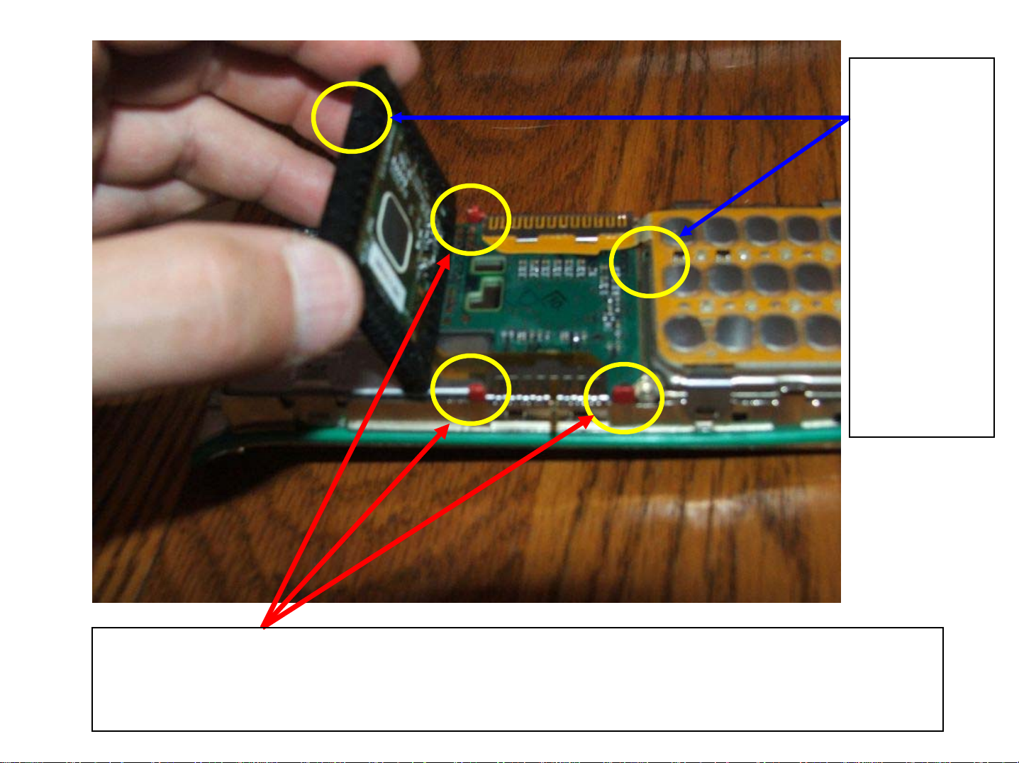
These are the three mounting posts for the LCD protector (black rubber
piece). Make sure the red plastic is on there as it helps retain the LCD
securely in place.
I normally just use the
plastic special tool for
this, but a small flat
blade screwdriver works
just as well. Note the
“finger” of the LCD flex
sticking out.
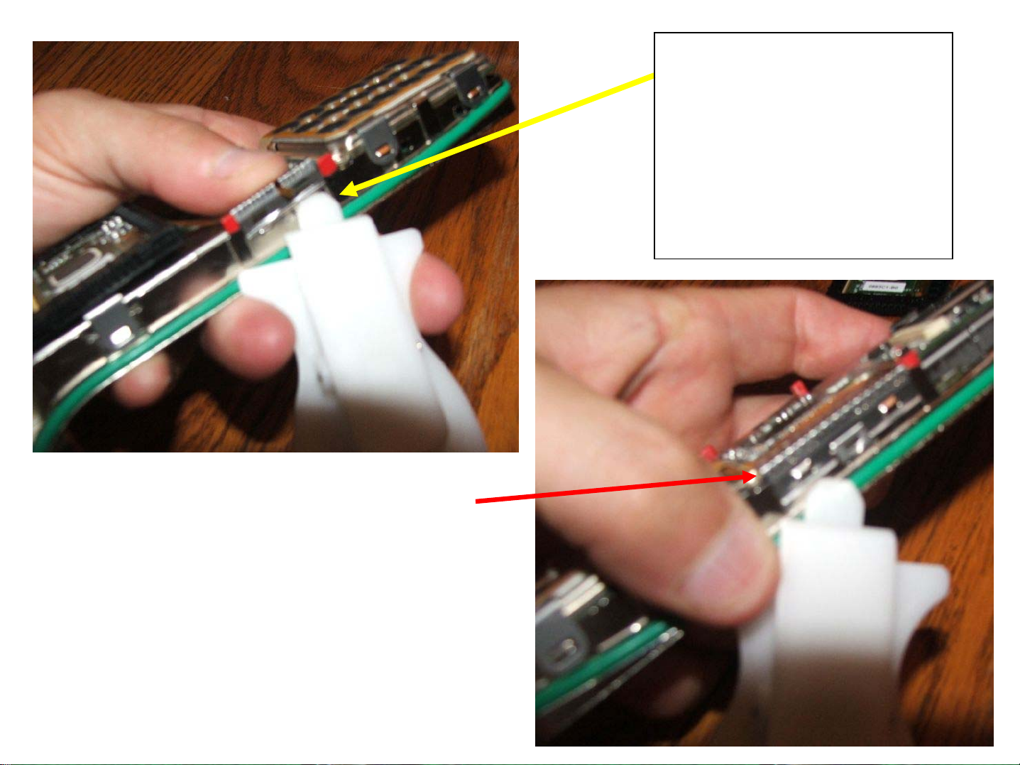
This is the keypad flex retainer,
again – a small flat blade works well
here too.

There are four small retainers that must be released to remove the keypad
Flex assembly. Once removed you can remove the entire keypad flex
assembly and set it aside. Note the flex retainer is completely released
from the chassis.
There is a small cutout that forms a notch that holds the
NCN6167 controller board in place. If you gently lift the
controller board up from the BOTTOM of the radio, it will slip
right out of the radio. Ensure the top of the controller board
engages this retainer notch during reassembly!
Nice view of the
NCN6167
controller board
and LCD assembly
after partial
removal…..oh by
the way… that
controller board is
about $400… and
the LCD is about
$80… so BE
CAREFUL!
(FYI, this board
stores your HOST
firmware).
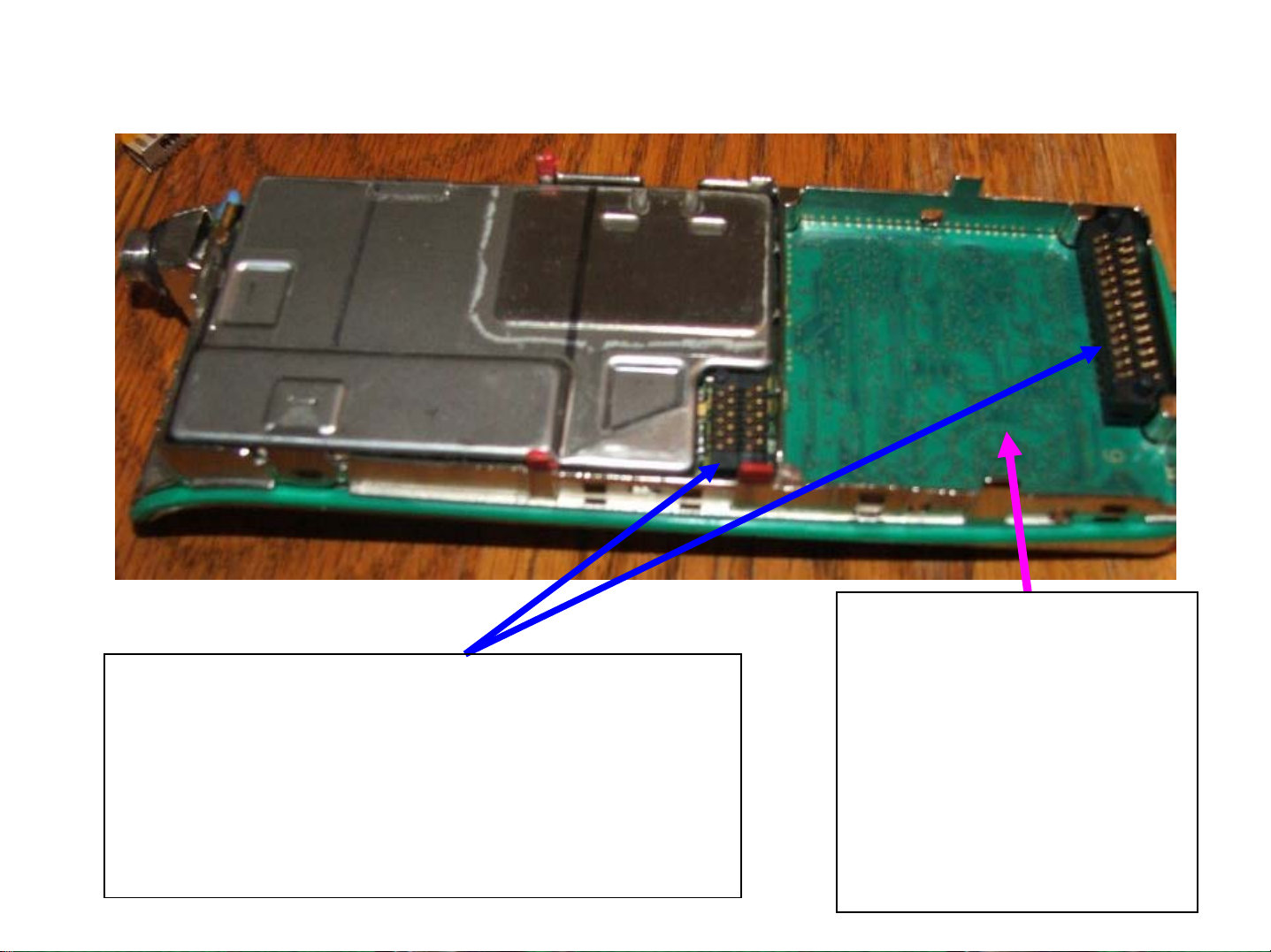
Now that the NCN6167 Controller board has been removed, this is what you’ll see:
These two header connectors route signals
between the controller board, the vocoder
and the RF board. INGENIOUS! They are
keyed to prevent installing them the wrong
way – but you need to watch reassembly
to ensure that they haven’t moved.
This is your
VOCODER. It’s not a
VOCON – It’s a
VOCODER. This is
where your DSP
firmware is stored.
Note that it’s installed
upside down.
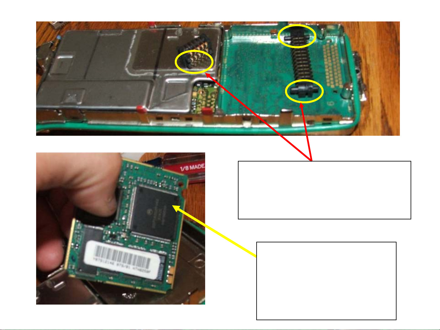
Note the keying lugs on these
connectors – they’re supposed to
be “sailor proof” – be sure you
put them in right!
The NTN8250 VOCODER
Be careful – don’t fry it or
drop it – current
replacement cost is
around $400.00
Removing the RF Shield… not required for my project… but shown to you!
There is one retainer clip on the left
side that must be removed….this is
the same style clip as the keypad….
And two detents need to be “popped” on
the right hand side to remove the RF
shield…..
There are two small detents that must be disengaged to remove
the RF board shield. Note the blue RF cable – be VERY careful
with this cable – it’s two ended – and connects the RF board to the
antenna connector – it’s VERY EASILY damaged.
You may have to use your small flat
blade screwdriver to GENTLY pry the
RF board shield free… BE CAREFUL!
RF Shield removed…..
The RF board is removed by lifting it from the LEFT side (long silver
can) and tilting it upward to free the two retainers from their detents in
the chassis (yellow circles)… if you are removing the RF board
completely, use a small pair of hemostats or fine needlenose pliers to
remove the RF cable from it’s socket on the RF board…..
 Loading...