

Page 1
WS5100 Series Switch
System Reference Guide
Page 2

© 2007 Motorola, Inc. All rights reserved.
MOTOROLA and the Stylized M Logo are registered in the US Patent & Trademark Office. Symbol is a registered
trademark of Symbol Technologies, Inc. All other product or service names are the property of their respective owners.
Page 3

Contents
Chapter 1. Overview
1.1 Hardware Overview. . . . . . . . . . . . . . . . . . . . . . . . . . . . . . . . . . . . . . . . . . . . . . . . . . . . . . . . . . . . . . . . . . . . . . . . . . . . 1-1
1.1.1 Physical Specifications . . . . . . . . . . . . . . . . . . . . . . . . . . . . . . . . . . . . . . . . . . . . . . . . . . . . . . . . . . . . . . . . . 1-2
1.1.2 System Status LED Codes . . . . . . . . . . . . . . . . . . . . . . . . . . . . . . . . . . . . . . . . . . . . . . . . . . . . . . . . . . . . . . . 1-2
1.1.3 10/100/1000 Port Status LED Codes. . . . . . . . . . . . . . . . . . . . . . . . . . . . . . . . . . . . . . . . . . . . . . . . . . . . . . . 1-3
1.2 Software Overview . . . . . . . . . . . . . . . . . . . . . . . . . . . . . . . . . . . . . . . . . . . . . . . . . . . . . . . . . . . . . . . . . . . . . . . . . . . . 1-4
1.2.1 Infrastructure Features . . . . . . . . . . . . . . . . . . . . . . . . . . . . . . . . . . . . . . . . . . . . . . . . . . . . . . . . . . . . . . . . . 1-4
1.2.2 Wireless Switching . . . . . . . . . . . . . . . . . . . . . . . . . . . . . . . . . . . . . . . . . . . . . . . . . . . . . . . . . . . . . . . . . . . . 1-7
1.2.3 Wired Switching . . . . . . . . . . . . . . . . . . . . . . . . . . . . . . . . . . . . . . . . . . . . . . . . . . . . . . . . . . . . . . . . . . . . . 1-16
1.2.4 Management Features. . . . . . . . . . . . . . . . . . . . . . . . . . . . . . . . . . . . . . . . . . . . . . . . . . . . . . . . . . . . . . . . . 1-17
1.2.5 Security Features . . . . . . . . . . . . . . . . . . . . . . . . . . . . . . . . . . . . . . . . . . . . . . . . . . . . . . . . . . . . . . . . . . . . . 1-18
1.2.6 Access Port Support. . . . . . . . . . . . . . . . . . . . . . . . . . . . . . . . . . . . . . . . . . . . . . . . . . . . . . . . . . . . . . . . . . . 1-24
Chapter 2. Switch Web UI Access and Image Upgrades
2.1 Accessing the Switch Web UI. . . . . . . . . . . . . . . . . . . . . . . . . . . . . . . . . . . . . . . . . . . . . . . . . . . . . . . . . . . . . . . . . . . . 2-1
2.1.1 Web UI Requirements . . . . . . . . . . . . . . . . . . . . . . . . . . . . . . . . . . . . . . . . . . . . . . . . . . . . . . . . . . . . . . . . . . 2-1
2.1.2 Connecting to the Switch Web UI . . . . . . . . . . . . . . . . . . . . . . . . . . . . . . . . . . . . . . . . . . . . . . . . . . . . . . . . . 2-2
2.2 Switch Password Recovery . . . . . . . . . . . . . . . . . . . . . . . . . . . . . . . . . . . . . . . . . . . . . . . . . . . . . . . . . . . . . . . . . . . . . . 2-3
2.3 Upgrading the Switch Image. . . . . . . . . . . . . . . . . . . . . . . . . . . . . . . . . . . . . . . . . . . . . . . . . . . . . . . . . . . . . . . . . . . . . 2-4
2.3.1 Upgrading the Switch Image from 1.4.x or 2.x to Version 3.x. . . . . . . . . . . . . . . . . . . . . . . . . . . . . . . . . . . . 2-4
2.4 Auto Installation . . . . . . . . . . . . . . . . . . . . . . . . . . . . . . . . . . . . . . . . . . . . . . . . . . . . . . . . . . . . . . . . . . . . . . . . . . . . . . 2-5
2.5 Downgrading the Switch Image . . . . . . . . . . . . . . . . . . . . . . . . . . . . . . . . . . . . . . . . . . . . . . . . . . . . . . . . . . . . . . . . . . 2-7
2.6 AP-4131 Access Point to Access Port Conversion . . . . . . . . . . . . . . . . . . . . . . . . . . . . . . . . . . . . . . . . . . . . . . . . . . . . 2-7
Chapter 3. Switch Information
3.1 Viewing the Switch Interface . . . . . . . . . . . . . . . . . . . . . . . . . . . . . . . . . . . . . . . . . . . . . . . . . . . . . . . . . . . . . . . . . . . . 3-1
3.1.1 Viewing the Switch Configuration. . . . . . . . . . . . . . . . . . . . . . . . . . . . . . . . . . . . . . . . . . . . . . . . . . . . . . . . . 3-2
3.1.2 Viewing Switch Statistics . . . . . . . . . . . . . . . . . . . . . . . . . . . . . . . . . . . . . . . . . . . . . . . . . . . . . . . . . . . . . . . 3-6
3.2 Viewing Switch Port Information . . . . . . . . . . . . . . . . . . . . . . . . . . . . . . . . . . . . . . . . . . . . . . . . . . . . . . . . . . . . . . . . . 3-8
3.2.1 Viewing the Port Configuration . . . . . . . . . . . . . . . . . . . . . . . . . . . . . . . . . . . . . . . . . . . . . . . . . . . . . . . . . . . 3-8
3.2.2 Viewing the Ports Runtime Status. . . . . . . . . . . . . . . . . . . . . . . . . . . . . . . . . . . . . . . . . . . . . . . . . . . . . . . . 3-10
3.2.3 Viewing the Ports Statistics . . . . . . . . . . . . . . . . . . . . . . . . . . . . . . . . . . . . . . . . . . . . . . . . . . . . . . . . . . . . 3-11
3.3 Viewing Switch Configurations. . . . . . . . . . . . . . . . . . . . . . . . . . . . . . . . . . . . . . . . . . . . . . . . . . . . . . . . . . . . . . . . . . 3-16
3.3.1 Viewing the Detailed Contents of a Config File . . . . . . . . . . . . . . . . . . . . . . . . . . . . . . . . . . . . . . . . . . . . . 3-17
3.3.2 Editing a Config File. . . . . . . . . . . . . . . . . . . . . . . . . . . . . . . . . . . . . . . . . . . . . . . . . . . . . . . . . . . . . . . . . . . 3-18
3.3.3 Transferring a Config File . . . . . . . . . . . . . . . . . . . . . . . . . . . . . . . . . . . . . . . . . . . . . . . . . . . . . . . . . . . . . . 3-19
3.4 Viewing Switch Firmware Information . . . . . . . . . . . . . . . . . . . . . . . . . . . . . . . . . . . . . . . . . . . . . . . . . . . . . . . . . . . . 3-20
3.4.1 Editing the Switch Firmware . . . . . . . . . . . . . . . . . . . . . . . . . . . . . . . . . . . . . . . . . . . . . . . . . . . . . . . . . . . . 3-21
Page 4

TOC-2 WS5100 Series Switch System Reference Guide
3.4.2 Enabling Global Settings for the Failover Image. . . . . . . . . . . . . . . . . . . . . . . . . . . . . . . . . . . . . . . . . . . . . 3-22
3.4.3 Updating the Switch Firmware . . . . . . . . . . . . . . . . . . . . . . . . . . . . . . . . . . . . . . . . . . . . . . . . . . . . . . . . . . 3-23
3.5 Configuring Automatic Updates . . . . . . . . . . . . . . . . . . . . . . . . . . . . . . . . . . . . . . . . . . . . . . . . . . . . . . . . . . . . . . . . . 3-24
3.6 Viewing the Switch Alarm Log . . . . . . . . . . . . . . . . . . . . . . . . . . . . . . . . . . . . . . . . . . . . . . . . . . . . . . . . . . . . . . . . . . 3-26
3.6.1 Viewing Alarm Log Details . . . . . . . . . . . . . . . . . . . . . . . . . . . . . . . . . . . . . . . . . . . . . . . . . . . . . . . . . . . . . 3-27
3.7 Viewing Switch Licenses . . . . . . . . . . . . . . . . . . . . . . . . . . . . . . . . . . . . . . . . . . . . . . . . . . . . . . . . . . . . . . . . . . . . . . 3-28
3.8 How to use the Filter Option . . . . . . . . . . . . . . . . . . . . . . . . . . . . . . . . . . . . . . . . . . . . . . . . . . . . . . . . . . . . . . . . . . . . 3-29
Chapter 4. Network Setup
4.1 Displaying the Network Interface . . . . . . . . . . . . . . . . . . . . . . . . . . . . . . . . . . . . . . . . . . . . . . . . . . . . . . . . . . . . . . . . . 4-1
4.2 Viewing Network IP Information. . . . . . . . . . . . . . . . . . . . . . . . . . . . . . . . . . . . . . . . . . . . . . . . . . . . . . . . . . . . . . . . . . 4-3
4.2.1 Configuring DNS . . . . . . . . . . . . . . . . . . . . . . . . . . . . . . . . . . . . . . . . . . . . . . . . . . . . . . . . . . . . . . . . . . . . . . 4-3
4.2.2 Configuring IP Forwarding . . . . . . . . . . . . . . . . . . . . . . . . . . . . . . . . . . . . . . . . . . . . . . . . . . . . . . . . . . . . . . . 4-5
4.2.3 Viewing Address Resolution . . . . . . . . . . . . . . . . . . . . . . . . . . . . . . . . . . . . . . . . . . . . . . . . . . . . . . . . . . . . . 4-8
4.3 Viewing and Configuring Layer 2 Virtual LANs. . . . . . . . . . . . . . . . . . . . . . . . . . . . . . . . . . . . . . . . . . . . . . . . . . . . . . . 4-9
4.3.1 Editing the Details of an Existing VLAN . . . . . . . . . . . . . . . . . . . . . . . . . . . . . . . . . . . . . . . . . . . . . . . . . . . 4-11
4.4 Configuring Switch Virtual Interfaces. . . . . . . . . . . . . . . . . . . . . . . . . . . . . . . . . . . . . . . . . . . . . . . . . . . . . . . . . . . . . 4-12
4.4.1 Configuring the Virtual Interface. . . . . . . . . . . . . . . . . . . . . . . . . . . . . . . . . . . . . . . . . . . . . . . . . . . . . . . . . 4-12
4.4.2 Viewing Virtual Interface Statistics. . . . . . . . . . . . . . . . . . . . . . . . . . . . . . . . . . . . . . . . . . . . . . . . . . . . . . . 4-15
4.5 Viewing and Configuring Switch WLANs . . . . . . . . . . . . . . . . . . . . . . . . . . . . . . . . . . . . . . . . . . . . . . . . . . . . . . . . . . 4-20
4.5.1 Configuring WLANs . . . . . . . . . . . . . . . . . . . . . . . . . . . . . . . . . . . . . . . . . . . . . . . . . . . . . . . . . . . . . . . . . . . 4-20
4.5.2 Viewing WLAN Statistics . . . . . . . . . . . . . . . . . . . . . . . . . . . . . . . . . . . . . . . . . . . . . . . . . . . . . . . . . . . . . . 4-45
4.5.3 Viewing VLAN/Tunnel Assignments . . . . . . . . . . . . . . . . . . . . . . . . . . . . . . . . . . . . . . . . . . . . . . . . . . . . . . 4-52
4.5.4 Configuring WMM. . . . . . . . . . . . . . . . . . . . . . . . . . . . . . . . . . . . . . . . . . . . . . . . . . . . . . . . . . . . . . . . . . . . 4-53
4.6 Viewing Associated MU Details . . . . . . . . . . . . . . . . . . . . . . . . . . . . . . . . . . . . . . . . . . . . . . . . . . . . . . . . . . . . . . . . . 4-57
4.6.1 Viewing MU Status . . . . . . . . . . . . . . . . . . . . . . . . . . . . . . . . . . . . . . . . . . . . . . . . . . . . . . . . . . . . . . . . . . . 4-57
4.6.2 Viewing MU Statistics. . . . . . . . . . . . . . . . . . . . . . . . . . . . . . . . . . . . . . . . . . . . . . . . . . . . . . . . . . . . . . . . . 4-60
4.7 Viewing Access Port Information . . . . . . . . . . . . . . . . . . . . . . . . . . . . . . . . . . . . . . . . . . . . . . . . . . . . . . . . . . . . . . . . 4-64
4.7.1 Configuring Access Port Radios. . . . . . . . . . . . . . . . . . . . . . . . . . . . . . . . . . . . . . . . . . . . . . . . . . . . . . . . . . 4-65
4.7.2 Viewing AP Statistics . . . . . . . . . . . . . . . . . . . . . . . . . . . . . . . . . . . . . . . . . . . . . . . . . . . . . . . . . . . . . . . . . 4-74
4.7.3 Configuring WLAN Assignment. . . . . . . . . . . . . . . . . . . . . . . . . . . . . . . . . . . . . . . . . . . . . . . . . . . . . . . . . . 4-78
4.7.4 Configuring WMM. . . . . . . . . . . . . . . . . . . . . . . . . . . . . . . . . . . . . . . . . . . . . . . . . . . . . . . . . . . . . . . . . . . . 4-80
4.8 Viewing Access Port Adoption Defaults . . . . . . . . . . . . . . . . . . . . . . . . . . . . . . . . . . . . . . . . . . . . . . . . . . . . . . . . . . . 4-82
4.8.1 Configuring AP Adoption Defaults. . . . . . . . . . . . . . . . . . . . . . . . . . . . . . . . . . . . . . . . . . . . . . . . . . . . . . . . 4-82
4.8.2 Configuring Layer 3 Access Port Adoption . . . . . . . . . . . . . . . . . . . . . . . . . . . . . . . . . . . . . . . . . . . . . . . . . 4-88
4.8.3 Configuring WLAN Assignment. . . . . . . . . . . . . . . . . . . . . . . . . . . . . . . . . . . . . . . . . . . . . . . . . . . . . . . . . . 4-88
4.8.4 Configuring WMM. . . . . . . . . . . . . . . . . . . . . . . . . . . . . . . . . . . . . . . . . . . . . . . . . . . . . . . . . . . . . . . . . . . . 4-90
4.9 Viewing Access Port Status . . . . . . . . . . . . . . . . . . . . . . . . . . . . . . . . . . . . . . . . . . . . . . . . . . . . . . . . . . . . . . . . . . . . 4-92
4.9.1 Viewing Adopted Access Ports . . . . . . . . . . . . . . . . . . . . . . . . . . . . . . . . . . . . . . . . . . . . . . . . . . . . . . . . . . 4-92
4.9.2 Viewing Unadopted Access Ports . . . . . . . . . . . . . . . . . . . . . . . . . . . . . . . . . . . . . . . . . . . . . . . . . . . . . . . . 4-93
Chapter 5. Switch Services
5.1 Displaying the Services Interface . . . . . . . . . . . . . . . . . . . . . . . . . . . . . . . . . . . . . . . . . . . . . . . . . . . . . . . . . . . . . . . . . 5-2
5.2 DHCP Server Settings . . . . . . . . . . . . . . . . . . . . . . . . . . . . . . . . . . . . . . . . . . . . . . . . . . . . . . . . . . . . . . . . . . . . . . . . . . 5-3
5.2.1 Configuring the Switch DHCP Server . . . . . . . . . . . . . . . . . . . . . . . . . . . . . . . . . . . . . . . . . . . . . . . . . . . . . . 5-3
5.2.2 Viewing the Attributes of Existing Host Pools . . . . . . . . . . . . . . . . . . . . . . . . . . . . . . . . . . . . . . . . . . . . . . 5-11
5.2.3 Configuring Excluded IP Address Information. . . . . . . . . . . . . . . . . . . . . . . . . . . . . . . . . . . . . . . . . . . . . . . 5-12
5.2.4 Configuring DHCP Server Relay Information. . . . . . . . . . . . . . . . . . . . . . . . . . . . . . . . . . . . . . . . . . . . . . . . 5-13
Page 5

TOC-3
5.2.5 Viewing DHCP Server Status. . . . . . . . . . . . . . . . . . . . . . . . . . . . . . . . . . . . . . . . . . . . . . . . . . . . . . . . . . . . 5-15
5.3 Configuring Secure NTP . . . . . . . . . . . . . . . . . . . . . . . . . . . . . . . . . . . . . . . . . . . . . . . . . . . . . . . . . . . . . . . . . . . . . . . 5-16
5.3.1 Defining the SNTP Configuration . . . . . . . . . . . . . . . . . . . . . . . . . . . . . . . . . . . . . . . . . . . . . . . . . . . . . . . . 5-16
5.3.2 Adding a New SNTP Symmetric Key. . . . . . . . . . . . . . . . . . . . . . . . . . . . . . . . . . . . . . . . . . . . . . . . . . . . . . 5-18
5.3.3 Defining a SNTP Neighbor Configuration . . . . . . . . . . . . . . . . . . . . . . . . . . . . . . . . . . . . . . . . . . . . . . . . . . 5-19
5.3.4 Adding an NTP Neighbor . . . . . . . . . . . . . . . . . . . . . . . . . . . . . . . . . . . . . . . . . . . . . . . . . . . . . . . . . . . . . . . 5-21
5.3.5 Viewing SNTP Associations . . . . . . . . . . . . . . . . . . . . . . . . . . . . . . . . . . . . . . . . . . . . . . . . . . . . . . . . . . . . 5-22
5.3.6 Viewing SNTP Status. . . . . . . . . . . . . . . . . . . . . . . . . . . . . . . . . . . . . . . . . . . . . . . . . . . . . . . . . . . . . . . . . . 5-24
5.4 Configuring Switch Redundancy . . . . . . . . . . . . . . . . . . . . . . . . . . . . . . . . . . . . . . . . . . . . . . . . . . . . . . . . . . . . . . . . . 5-25
5.4.1 Reviewing Redundancy Status . . . . . . . . . . . . . . . . . . . . . . . . . . . . . . . . . . . . . . . . . . . . . . . . . . . . . . . . . . 5-28
5.4.2 Configuring Redundancy Group Membership . . . . . . . . . . . . . . . . . . . . . . . . . . . . . . . . . . . . . . . . . . . . . . . 5-30
5.4.3 Redundancy Group License Aggregation Rules. . . . . . . . . . . . . . . . . . . . . . . . . . . . . . . . . . . . . . . . . . . . . . 5-34
5.5 Layer 3 Mobility. . . . . . . . . . . . . . . . . . . . . . . . . . . . . . . . . . . . . . . . . . . . . . . . . . . . . . . . . . . . . . . . . . . . . . . . . . . . . . 5-35
5.5.1 Configuring Layer 3 Mobility . . . . . . . . . . . . . . . . . . . . . . . . . . . . . . . . . . . . . . . . . . . . . . . . . . . . . . . . . . . . 5-35
5.5.2 Defining the Layer 3 Peer List . . . . . . . . . . . . . . . . . . . . . . . . . . . . . . . . . . . . . . . . . . . . . . . . . . . . . . . . . . . 5-38
5.5.3 Reviewing Layer 3 Peer List Statistics . . . . . . . . . . . . . . . . . . . . . . . . . . . . . . . . . . . . . . . . . . . . . . . . . . . . 5-39
5.5.4 Reviewing Layer 3 MU Status . . . . . . . . . . . . . . . . . . . . . . . . . . . . . . . . . . . . . . . . . . . . . . . . . . . . . . . . . . . 5-40
5.6 Configuring GRE Tunnels. . . . . . . . . . . . . . . . . . . . . . . . . . . . . . . . . . . . . . . . . . . . . . . . . . . . . . . . . . . . . . . . . . . . . . . 5-41
5.6.1 Editing the Properties of a GRE Tunnel . . . . . . . . . . . . . . . . . . . . . . . . . . . . . . . . . . . . . . . . . . . . . . . . . . . . 5-44
5.6.2 Adding a New GRE Tunnel . . . . . . . . . . . . . . . . . . . . . . . . . . . . . . . . . . . . . . . . . . . . . . . . . . . . . . . . . . . . . 5-45
5.7 Configuring Self Healing . . . . . . . . . . . . . . . . . . . . . . . . . . . . . . . . . . . . . . . . . . . . . . . . . . . . . . . . . . . . . . . . . . . . . . . 5-46
5.7.1 Configuring Self Healing Neighbor Details. . . . . . . . . . . . . . . . . . . . . . . . . . . . . . . . . . . . . . . . . . . . . . . . . 5-47
5.8 Configuring Switch Discovery . . . . . . . . . . . . . . . . . . . . . . . . . . . . . . . . . . . . . . . . . . . . . . . . . . . . . . . . . . . . . . . . . . . 5-50
5.8.1 Configuring Discovery Profiles. . . . . . . . . . . . . . . . . . . . . . . . . . . . . . . . . . . . . . . . . . . . . . . . . . . . . . . . . . . 5-50
5.8.2 Viewing Discovered Switches . . . . . . . . . . . . . . . . . . . . . . . . . . . . . . . . . . . . . . . . . . . . . . . . . . . . . . . . . . . 5-53
Chapter 6. Switch Security
6.1 Displaying the Main Security Interface . . . . . . . . . . . . . . . . . . . . . . . . . . . . . . . . . . . . . . . . . . . . . . . . . . . . . . . . . . . . 6-1
6.2 AP Intrusion Detection . . . . . . . . . . . . . . . . . . . . . . . . . . . . . . . . . . . . . . . . . . . . . . . . . . . . . . . . . . . . . . . . . . . . . . . . . 6-3
6.2.1 Enabling and Configuring AP Detection . . . . . . . . . . . . . . . . . . . . . . . . . . . . . . . . . . . . . . . . . . . . . . . . . . . . 6-3
6.2.2 Approved APs (Reported by APs). . . . . . . . . . . . . . . . . . . . . . . . . . . . . . . . . . . . . . . . . . . . . . . . . . . . . . . . . . 6-6
6.2.3 Unapproved APs (Reported by APs). . . . . . . . . . . . . . . . . . . . . . . . . . . . . . . . . . . . . . . . . . . . . . . . . . . . . . . . 6-7
6.2.4 Unapproved APs (Reported by MUs) . . . . . . . . . . . . . . . . . . . . . . . . . . . . . . . . . . . . . . . . . . . . . . . . . . . . . . . 6-8
6.3 MU Intrusion Detection. . . . . . . . . . . . . . . . . . . . . . . . . . . . . . . . . . . . . . . . . . . . . . . . . . . . . . . . . . . . . . . . . . . . . . . . . 6-9
6.3.1 Configuring MU Intrusion Detection . . . . . . . . . . . . . . . . . . . . . . . . . . . . . . . . . . . . . . . . . . . . . . . . . . . . . . . 6-9
6.3.2 Viewing Filtered MUs . . . . . . . . . . . . . . . . . . . . . . . . . . . . . . . . . . . . . . . . . . . . . . . . . . . . . . . . . . . . . . . . . 6-11
6.4 Configuring Wireless Filters . . . . . . . . . . . . . . . . . . . . . . . . . . . . . . . . . . . . . . . . . . . . . . . . . . . . . . . . . . . . . . . . . . . . 6-12
6.4.1 Editing an Existing Wireless Filter. . . . . . . . . . . . . . . . . . . . . . . . . . . . . . . . . . . . . . . . . . . . . . . . . . . . . . . . 6-14
6.4.2 Adding a new Wireless Filter . . . . . . . . . . . . . . . . . . . . . . . . . . . . . . . . . . . . . . . . . . . . . . . . . . . . . . . . . . . 6-15
6.4.3 Associating an ACL with WLAN . . . . . . . . . . . . . . . . . . . . . . . . . . . . . . . . . . . . . . . . . . . . . . . . . . . . . . . . . 6-16
6.5 Configuring ACLs. . . . . . . . . . . . . . . . . . . . . . . . . . . . . . . . . . . . . . . . . . . . . . . . . . . . . . . . . . . . . . . . . . . . . . . . . . . . . 6-16
6.5.1 ACL Overview. . . . . . . . . . . . . . . . . . . . . . . . . . . . . . . . . . . . . . . . . . . . . . . . . . . . . . . . . . . . . . . . . . . . . . . . 6-17
6.5.2 Configuring an ACL . . . . . . . . . . . . . . . . . . . . . . . . . . . . . . . . . . . . . . . . . . . . . . . . . . . . . . . . . . . . . . . . . . . 6-20
6.5.3 Attaching an ACL . . . . . . . . . . . . . . . . . . . . . . . . . . . . . . . . . . . . . . . . . . . . . . . . . . . . . . . . . . . . . . . . . . . . . 6-24
6.5.4 Attaching an ACL on a WLAN Interface/Port . . . . . . . . . . . . . . . . . . . . . . . . . . . . . . . . . . . . . . . . . . . . . . . 6-25
6.5.5 Reviewing ACL Statistics. . . . . . . . . . . . . . . . . . . . . . . . . . . . . . . . . . . . . . . . . . . . . . . . . . . . . . . . . . . . . . . 6-27
6.6 Configuring NAT Information . . . . . . . . . . . . . . . . . . . . . . . . . . . . . . . . . . . . . . . . . . . . . . . . . . . . . . . . . . . . . . . . . . . 6-28
6.6.1 Defining Dynamic NAT Translations . . . . . . . . . . . . . . . . . . . . . . . . . . . . . . . . . . . . . . . . . . . . . . . . . . . . . . 6-28
Page 6

TOC-4 WS5100 Series Switch System Reference Guide
6.6.2 Defining Static NAT Translations . . . . . . . . . . . . . . . . . . . . . . . . . . . . . . . . . . . . . . . . . . . . . . . . . . . . . . . . 6-31
6.6.3 Configuring NAT Interfaces . . . . . . . . . . . . . . . . . . . . . . . . . . . . . . . . . . . . . . . . . . . . . . . . . . . . . . . . . . . . . 6-34
6.6.4 Viewing NAT Status . . . . . . . . . . . . . . . . . . . . . . . . . . . . . . . . . . . . . . . . . . . . . . . . . . . . . . . . . . . . . . . . . . 6-35
6.7 Configuring IKE Settings . . . . . . . . . . . . . . . . . . . . . . . . . . . . . . . . . . . . . . . . . . . . . . . . . . . . . . . . . . . . . . . . . . . . . . . 6-36
6.7.1 Defining the IKE Configuration . . . . . . . . . . . . . . . . . . . . . . . . . . . . . . . . . . . . . . . . . . . . . . . . . . . . . . . . . . 6-37
6.7.2 Setting IKE Policies . . . . . . . . . . . . . . . . . . . . . . . . . . . . . . . . . . . . . . . . . . . . . . . . . . . . . . . . . . . . . . . . . . . 6-38
6.7.3 Viewing SA Statistics . . . . . . . . . . . . . . . . . . . . . . . . . . . . . . . . . . . . . . . . . . . . . . . . . . . . . . . . . . . . . . . . . 6-42
6.8 Configuring IPSec VPN . . . . . . . . . . . . . . . . . . . . . . . . . . . . . . . . . . . . . . . . . . . . . . . . . . . . . . . . . . . . . . . . . . . . . . . . 6-43
6.8.1 Defining the IPSec Configuration . . . . . . . . . . . . . . . . . . . . . . . . . . . . . . . . . . . . . . . . . . . . . . . . . . . . . . . . 6-45
6.8.2 Defining the IPSec VPN Remote Configuration. . . . . . . . . . . . . . . . . . . . . . . . . . . . . . . . . . . . . . . . . . . . . . 6-49
6.8.3 Configuring IPSEC VPN Authentication . . . . . . . . . . . . . . . . . . . . . . . . . . . . . . . . . . . . . . . . . . . . . . . . . . . . 6-50
6.8.4 Configuring Crypto Maps. . . . . . . . . . . . . . . . . . . . . . . . . . . . . . . . . . . . . . . . . . . . . . . . . . . . . . . . . . . . . . . 6-52
6.8.5 Viewing IPSec Security Associations . . . . . . . . . . . . . . . . . . . . . . . . . . . . . . . . . . . . . . . . . . . . . . . . . . . . . 6-61
6.9 Configuring the Radius Server . . . . . . . . . . . . . . . . . . . . . . . . . . . . . . . . . . . . . . . . . . . . . . . . . . . . . . . . . . . . . . . . . . 6-62
6.9.1 Radius Overview . . . . . . . . . . . . . . . . . . . . . . . . . . . . . . . . . . . . . . . . . . . . . . . . . . . . . . . . . . . . . . . . . . . . . 6-62
6.9.2 Using the Switch’s Radius Server Versus an External Radius . . . . . . . . . . . . . . . . . . . . . . . . . . . . . . . . . . 6-64
6.9.3 Defining the Radius Configuration . . . . . . . . . . . . . . . . . . . . . . . . . . . . . . . . . . . . . . . . . . . . . . . . . . . . . . . 6-65
6.9.4 Configuring Radius Authentication and Accounting . . . . . . . . . . . . . . . . . . . . . . . . . . . . . . . . . . . . . . . . . . 6-67
6.9.5 Configuring Radius Users . . . . . . . . . . . . . . . . . . . . . . . . . . . . . . . . . . . . . . . . . . . . . . . . . . . . . . . . . . . . . . 6-69
6.9.6 Configuring Radius User Groups . . . . . . . . . . . . . . . . . . . . . . . . . . . . . . . . . . . . . . . . . . . . . . . . . . . . . . . . . 6-71
6.9.7 Viewing Radius Accounting Logs . . . . . . . . . . . . . . . . . . . . . . . . . . . . . . . . . . . . . . . . . . . . . . . . . . . . . . . . 6-73
6.10 Creating Server Certificates . . . . . . . . . . . . . . . . . . . . . . . . . . . . . . . . . . . . . . . . . . . . . . . . . . . . . . . . . . . . . . . . . . . . 6-74
6.10.1 Using Trustpoints to Configure Certificates . . . . . . . . . . . . . . . . . . . . . . . . . . . . . . . . . . . . . . . . . . . . . . . . 6-75
6.10.2 Configuring Trustpoint Associated Keys . . . . . . . . . . . . . . . . . . . . . . . . . . . . . . . . . . . . . . . . . . . . . . . . . . . 6-81
Chapter 7. Switch Management
7.1 Displaying the Management Access Interface. . . . . . . . . . . . . . . . . . . . . . . . . . . . . . . . . . . . . . . . . . . . . . . . . . . . . . . 7-1
7.2 Configuring Access Control. . . . . . . . . . . . . . . . . . . . . . . . . . . . . . . . . . . . . . . . . . . . . . . . . . . . . . . . . . . . . . . . . . . . . . 7-2
7.3 Configuring SNMP Access . . . . . . . . . . . . . . . . . . . . . . . . . . . . . . . . . . . . . . . . . . . . . . . . . . . . . . . . . . . . . . . . . . . . . . 7-4
7.3.1 Configuring SNMP v1/v2 Access. . . . . . . . . . . . . . . . . . . . . . . . . . . . . . . . . . . . . . . . . . . . . . . . . . . . . . . . . . 7-5
7.3.2 Configuring SNMP v3 Access . . . . . . . . . . . . . . . . . . . . . . . . . . . . . . . . . . . . . . . . . . . . . . . . . . . . . . . . . . . . 7-6
7.3.3 Accessing SNMP v2/v3 Statistics . . . . . . . . . . . . . . . . . . . . . . . . . . . . . . . . . . . . . . . . . . . . . . . . . . . . . . . . . 7-9
7.4 Configuring SNMP Traps. . . . . . . . . . . . . . . . . . . . . . . . . . . . . . . . . . . . . . . . . . . . . . . . . . . . . . . . . . . . . . . . . . . . . . . 7-11
7.4.1 Enabling Trap Configuration . . . . . . . . . . . . . . . . . . . . . . . . . . . . . . . . . . . . . . . . . . . . . . . . . . . . . . . . . . . . 7-11
7.4.2 Configuring Trap Thresholds . . . . . . . . . . . . . . . . . . . . . . . . . . . . . . . . . . . . . . . . . . . . . . . . . . . . . . . . . . . . 7-13
7.5 Configuring SNMP Trap Receivers . . . . . . . . . . . . . . . . . . . . . . . . . . . . . . . . . . . . . . . . . . . . . . . . . . . . . . . . . . . . . . . 7-16
7.5.1 Editing SNMP Trap Receivers . . . . . . . . . . . . . . . . . . . . . . . . . . . . . . . . . . . . . . . . . . . . . . . . . . . . . . . . . . . 7-17
7.5.2 Adding SNMP Trap Receivers . . . . . . . . . . . . . . . . . . . . . . . . . . . . . . . . . . . . . . . . . . . . . . . . . . . . . . . . . . . 7-17
7.6 Configuring Management Users . . . . . . . . . . . . . . . . . . . . . . . . . . . . . . . . . . . . . . . . . . . . . . . . . . . . . . . . . . . . . . . . . 7-18
7.6.1 Configuring Local Users. . . . . . . . . . . . . . . . . . . . . . . . . . . . . . . . . . . . . . . . . . . . . . . . . . . . . . . . . . . . . . . . 7-18
7.6.2 Configuring Switch Authentication . . . . . . . . . . . . . . . . . . . . . . . . . . . . . . . . . . . . . . . . . . . . . . . . . . . . . . . 7-23
Chapter 8. Diagnostics
8.1 Displaying the Main Diagnostic Interface . . . . . . . . . . . . . . . . . . . . . . . . . . . . . . . . . . . . . . . . . . . . . . . . . . . . . . . . . . 8-1
8.1.1 Switch Environment. . . . . . . . . . . . . . . . . . . . . . . . . . . . . . . . . . . . . . . . . . . . . . . . . . . . . . . . . . . . . . . . . . . . 8-2
8.1.2 CPU Performance . . . . . . . . . . . . . . . . . . . . . . . . . . . . . . . . . . . . . . . . . . . . . . . . . . . . . . . . . . . . . . . . . . . . . . 8-3
8.1.3 Switch Memory Allocation . . . . . . . . . . . . . . . . . . . . . . . . . . . . . . . . . . . . . . . . . . . . . . . . . . . . . . . . . . . . . . 8-4
8.1.4 Switch Disk Allocation. . . . . . . . . . . . . . . . . . . . . . . . . . . . . . . . . . . . . . . . . . . . . . . . . . . . . . . . . . . . . . . . . . 8-4
Page 7

TOC-5
8.1.5 Switch Memory Processes . . . . . . . . . . . . . . . . . . . . . . . . . . . . . . . . . . . . . . . . . . . . . . . . . . . . . . . . . . . . . . 8-5
8.1.6 Other Switch Resources . . . . . . . . . . . . . . . . . . . . . . . . . . . . . . . . . . . . . . . . . . . . . . . . . . . . . . . . . . . . . . . . 8-6
8.2 Configuring System Logging . . . . . . . . . . . . . . . . . . . . . . . . . . . . . . . . . . . . . . . . . . . . . . . . . . . . . . . . . . . . . . . . . . . . . 8-7
8.2.1 Log Options . . . . . . . . . . . . . . . . . . . . . . . . . . . . . . . . . . . . . . . . . . . . . . . . . . . . . . . . . . . . . . . . . . . . . . . . . . 8-7
8.2.2 File Management. . . . . . . . . . . . . . . . . . . . . . . . . . . . . . . . . . . . . . . . . . . . . . . . . . . . . . . . . . . . . . . . . . . . . . 8-9
8.3 Reviewing Core Snapshots . . . . . . . . . . . . . . . . . . . . . . . . . . . . . . . . . . . . . . . . . . . . . . . . . . . . . . . . . . . . . . . . . . . . . 8-12
8.3.1 Transferring Core Snapshots . . . . . . . . . . . . . . . . . . . . . . . . . . . . . . . . . . . . . . . . . . . . . . . . . . . . . . . . . . . . 8-13
8.4 Reviewing Panic Snapshots . . . . . . . . . . . . . . . . . . . . . . . . . . . . . . . . . . . . . . . . . . . . . . . . . . . . . . . . . . . . . . . . . . . . 8-14
8.4.1 Viewing Panic Details . . . . . . . . . . . . . . . . . . . . . . . . . . . . . . . . . . . . . . . . . . . . . . . . . . . . . . . . . . . . . . . . . 8-16
8.4.2 Transferring Panic Files . . . . . . . . . . . . . . . . . . . . . . . . . . . . . . . . . . . . . . . . . . . . . . . . . . . . . . . . . . . . . . . . 8-16
8.5 Debugging the Applet . . . . . . . . . . . . . . . . . . . . . . . . . . . . . . . . . . . . . . . . . . . . . . . . . . . . . . . . . . . . . . . . . . . . . . . . . 8-17
8.6 Configuring a Ping . . . . . . . . . . . . . . . . . . . . . . . . . . . . . . . . . . . . . . . . . . . . . . . . . . . . . . . . . . . . . . . . . . . . . . . . . . . . 8-18
8.6.1 Modifying the Configuration of an Existing Ping Test. . . . . . . . . . . . . . . . . . . . . . . . . . . . . . . . . . . . . . . . . 8-20
8.6.2 Adding a New Ping Test . . . . . . . . . . . . . . . . . . . . . . . . . . . . . . . . . . . . . . . . . . . . . . . . . . . . . . . . . . . . . . . 8-20
8.6.3 Viewing Ping Statistics . . . . . . . . . . . . . . . . . . . . . . . . . . . . . . . . . . . . . . . . . . . . . . . . . . . . . . . . . . . . . . . . 8-22
Page 8

TOC-6 WS5100 Series Switch System Reference Guide
Page 9
Introduction
This guide provides information about using the WS5100 Series Switch.
About This Guide
NOTE: Screens and windows pictured in this guide are samples and can differ from actual
screens.
Documentation Set
The documentation set for the WS5100 Series Switch is partitioned into the following guides to provide
information for specific user needs.
• WS5100 Installation Guide - describes the basic setup and configuration required to transition to more
advanced configuration of the switch.
• WS5100 CLI Reference - describes the Command Line Interface (CLI) and Management Information
Base (MIB) commands used to configure the WS5100 Series Switch.
• WS5100 Migration Guide - provides upgrade instructions and new feature descriptions for legacy
users of the WS5100 Series Switch.
• WS5100 Troubleshooting Guide- describes workarounds to known conditions the user may encounter.
• RF Management Software Users Guide - describes how to use Motorola RFMS to set up and monitor
your WS5100 in respect to areas of good RF throughput and defined physical barriers.
Document Conventions
The following conventions are used in this document to draw your attention to important information:
NOTE: Indicate tips or special requirements.
CAUTION: Indicates conditions that can cause equipment damage or data loss.
!
WARNING! Indicates a condition or procedure that could result in
personal injury or equipment damage.
Page 10

viii WS5100 Series Switch System Reference Guide
Notational Conventions
The following additional notational conventions are used in this document:
• Italics are used to highlight the following:
• Chapters and sections in this and related documents
• Dialog box, window and screen names
• Drop-down list and list box names
• Check box and radio button names
• Icons on a screen.
• GUI text is used to highlight the following:
• Screen names
• Menu items
• Button names on a screen.
• bullets (•) indicate:
• Action items
• Lists of alternatives
• Lists of required steps that are not necessarily sequential
• Sequential lists (e.g., those that describe step-by-step procedures) appear as numbered lists.
Page 11

Overview
The switch provides a centralized management solution for wireless networking components across the
wired network infrastructure. The switch connects to legacy access ports through a Layer 2 switch/hub. The
switch connects to non-legacy access ports through a Layer 3 interface.
The switch functions as the center of the wireless network. The access ports function as radio antennas for
data traffic management and routing. All of the system configuration and intelligence for the wireless
network resides in the switch.
The switch uses access ports to bridge data from associated wireless devices to the wireless switch. The
wireless switch applies appropriate policies to the data packets before routing them to their destination.
Data packets destined for devices on the wired network are processed by the switch, where appropriate
policies are applied before they are encapsulated and sent to their destination.
Access port configuration is managed by the switch through the Graphical User Interface (GUI), SNMP or the
Command Line Interface (CLI). The switch streamlines the management of a large wireless system and
allows for Quality of Service (QoS), virtual WLANs and packet forwarding implementations.
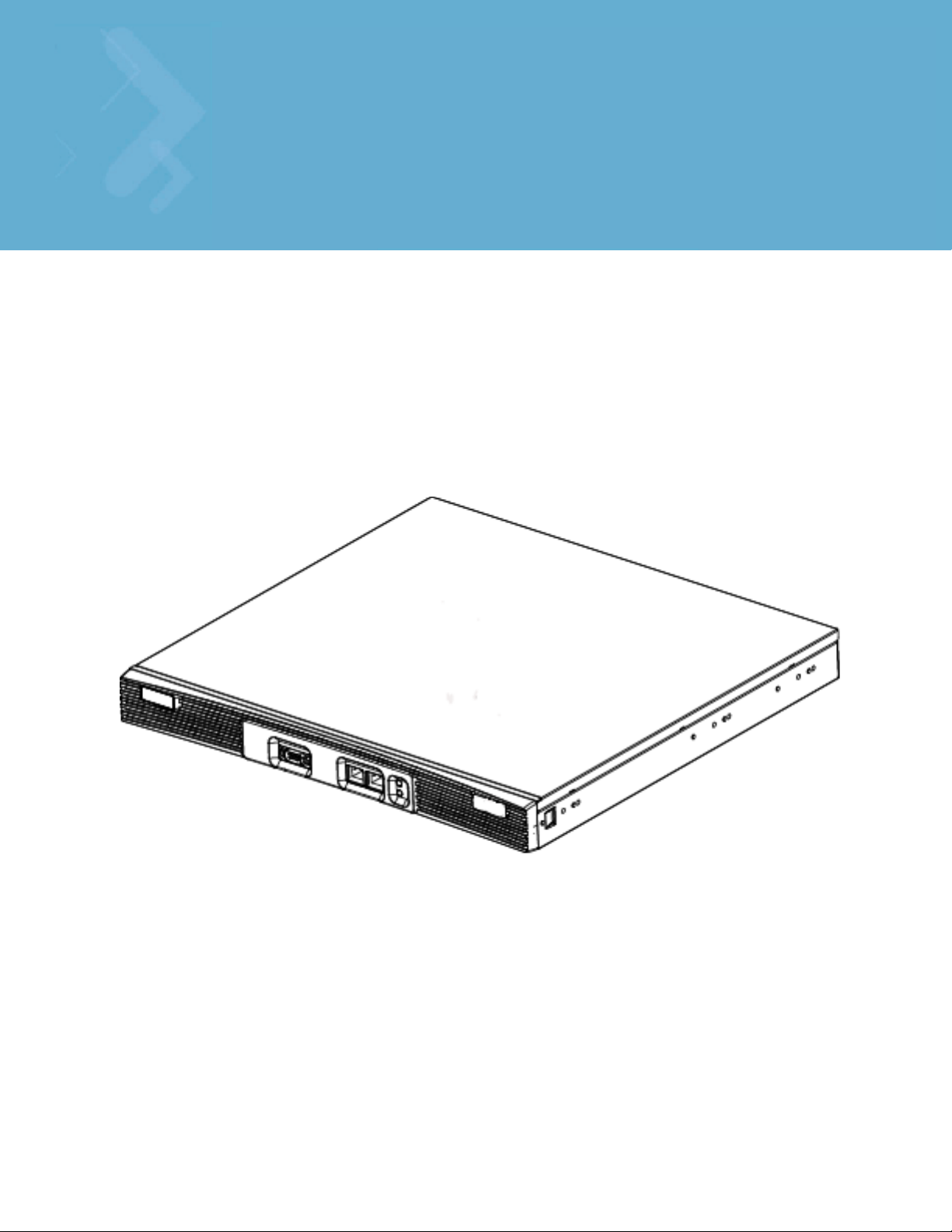
1.1 Hardware Overview
The wireless switch is a rack-mountable device that manages all inbound and outbound traffic on the
wireless network. It provides security, network service and system management applications.
Unlike traditional wireless infrastructure devices that reside at the edge of a network, the switch uses
centralized, policy-based management to apply sets of rules or actions to all devices on the wireless
network. It collects management “intelligence” from individual access points and moves the collected
information into the centralized switch. Then, it replaces access points with “dumb” radio antennas called
access ports.
Access ports (APs) are 48V power-over-Ethernet devices connected to the switch by an Ethernet cable. An
access port receives 802.11x data from MUs and forwards the data to the switch which applies the
appropriate policies and routes the packets to their destinations. Depending on the model, an AP can support
as many as 16 WLANs.
Access ports do not have software or firmware upon initial receipt from the factory. When the access port is
first powered on and cleared for the network, the switch initializes the access port and installs a small
firmware file automatically. Therefore, installation and firmware upgrades are automatic and transparent.
Page 12

1-2 WS5100 Series Switch System Reference Guide
1.1.1 Physical Specifications
The physical dimensions and operating parameters of the WS5100 Series Switch include:
Width 48.1 cm / 18.93 in. (with mounting brackets)
42.9 cm / 16.89 in. (without mounting brackets)
Height 4.39 cm / 1.73 in.
Depth 40.46 cm / 15.93 in.
Weight 6.25 kg / 13.75 lbs.
Max Power Consumption 100 VAC, 50/60 Hz, 3A
240 VAC, 50/60 Hz, 1.5A
Operating Temperature 10°C - 35°C / 50°F - 95°F
Operating Humidity 5% - 85% without condensation
1.1.1.1 Power Cord Specifications
A power cord is not supplied with the device. Use only a correctly rated power cord certified for the country
of operation
.
1.1.1.2 Power Protection
To best protect the switch from unexpected power surges or other power-related problems, ensure the
system installation meets the following power protection guidelines:
• If possible, use a dedicated circuit to protect data processing equipment. Commercial electrical
contractors are familiar with wiring for data processing equipment and can help with the load balancing
of dedicated circuits.
• Install surge protection. Use a surge protection device between the electricity source and the switch.
• Install an Uninterruptible Power Supply (UPS). A UPS provides continuous power during a power outage.
Some UPS devices have integral surge protection. UPS equipment requires periodic maintenance to
ensure reliability.
1.1.1.3 Cabling Requirements
Two Category 6 Ethernet cables (not supplied) are required to connect the switch to the LAN and the WLAN.
The cables are used with the two Ethernet ports on the front panel of the switch.
The console cable that comes with the switch is used to connect the switch to a computer running a serial
terminal emulator program to access the switch’s Command Line Interface (CLI) for initial configuration.
Initial configuration steps are described in the WS5100 Series Switch Installation Guide.
1.1.2 System Status LED Codes
A WS5100 has two LEDs on the front panel (adjacent to the RJ45 ports). The System Status LEDs display
three colors—blue, amber, or red —and three “lit” states—solid, blinking, or off.
Page 13

1.1.2.1 Start Up
Power off Off Off
Power On Self Test (POST) running All colors in rotation All colors in rotation
POST succeeded Blue solid Blue solid
1.1.2.2 Primary
Active (Continually Adopting Access Ports) Blue blinking Blue solid
No License to Adopt Amber blinking Amber blinking
1.1.2.3 Standby
Overview 1-3
Event Top LED Bottom LED
Event Top LED Bottom LED
Event Top LED Bottom LED
Active (Failed Over and Adopting Ports) Blue blinking Blue blinking
Active (Not Failed Over) Blue blinking Amber solid
1.1.2.4 Error Codes
Event Top LED Bottom LED
POST failed (critical error) Red blinking Red blinking
Software initialization failed Amber solid Off
Country code not configured.
Note: During first time setup, the LEDs will remain
in this state until the country code is configured.
No access ports have been adopted Blue blinking Amber blinking
1.1.3 10/100/1000 Port Status LED Codes
A WS5100 Series Switch has two LED indicators for its RJ-45 ports:
• Upper left (amber/green) for link rate
• Upper right (green) for link activity
Amber solid Amber blinking
The following table provides additional information about the status of the 10/100/1000 Port Status LEDs.
Page 14

1-4 WS5100 Series Switch System Reference Guide
LED State Meaning
Upper left Off 10 Mbps link rate
Green steady 100 Mbps link rate
Amber steady 1 Gigabit link rate
Upper right Off The port isn’t linked
Green steady The port is linked
Green blinking The port is linked and active
1.2 Software Overview
The switch includes a robust set of features.This section provides an overview of the software and features.
The features are listed and described in the following sections:
• Infrastructure Features
• Wireless Switching
• Wired Switching
• Management Features
• Security Features
• Access Port Support
NOTE: The Motorola RF Management Software is also a recommended utility to plan the
deployment of the switch and view its configuration once operational in the field.
Motorola RFMS can help optimize the positioning and configuration of a switch in respect
to a WLAN’s MU throughput requirements and can help detect rogue devices. For more
information, refer to the Motorola Web site.
1.2.1 Infrastructure Features
The switch includes the following Infrastructure features:
• Installation Feature
• Licensing Support
• Configuration Management
• Diagnostics
• Serviceability
• Tracing / Logging
• Process Monitor
• Hardware Abstraction Layer and Drivers
• Redundancy
• Secure Network Time Protocol (SNTP)
• Password Recovery
Page 15
1.2.1.1 Installation Feature
The upgrade/downgrade of the switch can be performed at boot time using one of the following methods:
•Web UI
•DHCP
•CLI
•SNMP
• Patches
NOTE: HTTPS must be enabled to access the switch Web UI. Ensure that HTTPS access
has been enabled before using the login screen to access the switch Web UI.
The switch platform has sufficient non-volatile memory to store multiple firmware images. The switch stores
an active and a passive firmware image. The switch supports staged upgrade operations.
1.2.1.2 Licensing Support
The following licensing information is utilized when upgrading the switch.
Overview 1-5
• The maximum numbers of AP licenses a switch can adopt is 48.
• You can install/remove AP licenses in batches of 6 APs at a time.
• The Radius server and VPN capability is not a part of the licenses feature.
1.2.1.3 Configuration Management
The system supports redundant storage of configuration files to protect against corruption during a write
operation and ensures at any given time a valid configuration file exists. If a configuration file has failed to
completely execute, it is rolled back and the pre-write file is used.
Text Based Configuration
The configuration is stored in human readable format. It is stored as a set of CLI commands.
1.2.1.4 Diagnostics
The following diagnostics are available for the switch:
1. In-service Diagnostics – In-service diagnostics provide a range of automatic health monitoring features
ensuring both the system hardware and software are in working order. The in-service-diagnostics
continuously monitor any available physical characteristics (as detailed below) and issues log messages
when either warning or error thresholds are reached. There are three types of in-service diagnostics:
• Hardware– Ethernet ports, chip failures, system temperature via the temperature sensors provided
by the hardware, etc.
• Software– CPU load, memory usage, etc.
• Environmental– CPU and air temperature, fans speed, etc.
2. Out-of-service Diagnostics – Out-of-service diagnostics are a set of intrusive tests run from the user
interface. Out-of-service diagnostics cannot be run while the unit is in operation. The intrusive tests
include:
• Ethernet loopback tests
Page 16

1-6 WS5100 Series Switch System Reference Guide
• RAM tests, Real Time Clock tests, etc.
3. Manufacturing Diagnostics – Manufacturing diagnostics are a set of diagnostics used by manufacturing
to inspect quality of hardware.
1.2.1.5 Serviceability
A special set of Service CLI commands are available to provide additional troubleshooting capabilities for
service personnel (for example, check the time critical processes were started), access to Linux services,
panic logs, etc. Only authorized users or service personnel are provided access to the Service CLI.
A built-in Packet Sniffer allows service personnel to capture incoming and outgoing packets in a buffer.
The switch also maintains various statistics for RF activity, Ethernet ports etc. RF statistics include roaming
stats, packet counters, octets tx/rx, signal, noise SNR, retry, and information for each MU.
1.2.1.6 Tracing / Logging
Log messages are well-defined and documented system messages with various destinations. They are
numbered and referenced by ID. Each severity level group, can be configured separately to go to either the
serial console, telnet interface, log file or remote syslog server.
Trace messages are more free-form and are used mainly by support personnel for tracking problems. They
are enabled or disabled via CLI commands. Trace messages can go to a log file, the serial console, or the
current tty.
Log and trace messages are interleaved in the same log file, so chronological order is preserved. Log and
trace messages from different processes are similarly interleaved in the same file for the same reason.
Log message format is similar to the format used by syslog messages (RFC 3164). Log messages include
message severity, source (facility), the time the message was generated and a textual message describing
the situation triggering the event. For more information on using the switch logging functionality, see
Configuring System Logging on page 8-7.
1.2.1.7 Process Monitor
The Process Monitor constantly checks to ensure processes under its control are up and running. Each
monitored process sends the Process Monitor periodic heartbeat messages. A process that is down (due to
a software crash or stuck in an endless loop) is detected when its heartbeat is not received. Such a process
is terminated (if still running) and restarted (if configured) by the Process Monitor.
1.2.1.8 Hardware Abstraction Layer and Drivers
The Hardware Abstraction Layer (HAL) provides an abstraction library with an interface hiding hardware/
platform specific data. Drivers include platform specific components such as Ethernet, Flash Memory storage
and thermal sensors.
1.2.1.9 Redundancy
Using the switch redundancy functionality, up to 12 switches can be configured in a redundancy group (and
thereby provide group monitoring). In the event of a switch failure, a switch within the cluster takes control.
Therefore, the switch supported network is always up and running even if a switch fails or is removed for
maintenance or software upgrade. Switch redundancy provides minimal traffic disruption in the event of a
switch failure or intermediate network failure.
The following redundancy features are supported:
Page 17

• Up to 12 switch redundancy members supported per group. Each member is capable of tracking statistics
for the entire group in addition to their own.
• Each redundancy group is capable of supporting an Active/Active configuration. Each redundancy group
can support two or more primary members, each responsible for group load sharing.
• Members within the same redundancy group can be deployed across different subnets and maintain their
interdependence as redundancy group members.
• Each member of the redundancy group supports AP load balancing by default.
• Members of the redundancy group support license aggregation. When a new member joins the group,
the new member can leverage the access port adoption license(s) of existing members.
• Each member of the redundancy group (including the reporting switch) capable of displaying cluster
performance statistics for all members in addition to their own.
• Centralized redundancy group management using the switch CLI.
For more information on configuring the switch for redundancy group support, see
Configuring Switch Redundancy on page 5-25.
1.2.1.10 Secure Network Time Protocol (SNTP)
Overview 1-7
Secure Network Time Protocol (SNTP) manages time and/or network clock synchronization within the switch
managed network environment. SNTP is a client/server implementation. The switch (a SNTP client)
periodically synchronizes its clock with a master clock (an NTP server). For example, the switch resets its
clock to 07:04:59 upon reading a time of 07:04:59 from its designated NTP server. Time synchronization is
recommended for the switch’s network operations. The following additionally hold true:
• The switch can be configured to provide NTP services to NTP clients.
• The switch can provide NTP support for user authentication.
• Secure Network Time Protocol (SNTP) clients can be configured to synchronize switch time with an
external NTP server.
For information on configuring the switch to support SNTP, see Configuring Secure NTP on page 5-16.
1.2.1.11 Password Recovery
The switch has a provision enabling the switch to restore its factory default configuration if your password
is lost. In doing so however the current configuration is erased and can be restored assuming if has been
exported to a secure location. For information on password recovery, see
Switch Password Recovery on page 2-3.
1.2.2 Wireless Switching
The switch includes the following wireless switching features:
• Physical Layer Features
• Rate Limiting
• Proxy-ARP
• HotSpot / IP Redirect
• IDM (Identity Driven Management)
• Voice Prioritization
Page 18

1-8 WS5100 Series Switch System Reference Guide
• Self Healing
• Wireless Capacity
• AP and MU Load Balancing
• Wireless Roaming
• Power Save Polling
• QoS
• Wireless Layer 2 Switching
• Automatic Channel Selection
• WMM-Unscheduled APSD
1.2.2.1 Physical Layer Features
802.11a
• DFS Radar Avoidance – Dynamic Frequency Selection (DFS) functionality is mandatory for WLAN
equipment that is intended to operate in the frequency bands 5150 MHz to 5350 MHz and 5470 MHz to
5725 MHz when the equipment operates in the countries of EU.
The purpose of DFS is:
• Detect interference from other systems and avoid co-channeling with those systems, most notably
radar systems.
• Provide uniform loading of the spectrum across all devices.
This feature is enabled automatically when the country code indicates that DFS is required for at
least one of the frequency bands that are allowed in the country.
• TPC – Transmit Power Control (TPC) meets the regulatory requirement for maximum power and mitigation
for each channel. The TPC functionality is enabled automatically for every AP that operates on the
channel.
802.11bg
• Dual mode b/g protection – The ERP builds on the payload data rates of 1 and 2 Mbit/s that use DSSS
modulation and builds on the payload data rates of 1, 2, 5.5, and 11 Mbit/s, that use DSSS, CCK, and
optional PBCC modulations. ERP provides additional payload data rates of 6, 9, 12, 18, 24, 36, 48, and 54
Mbit/s. Of these rates, transmission and reception capability for 1, 2, 5.5, 11, 6, 12, and 24 Mbit/s data
rates is mandatory.
Two additional optional ERP-PBCC modulation modes with payload data rates of 22 and 33 Mbit/s are
defined. An ERP-PBCC station may implement 22 Mbit/s alone or 22 and 33 Mbit/s. An optional
modulation mode known as DSSS-OFDM is also incorporated with payload data rates of 6, 9, 12, 18, 24,
36, 48, and 54 Mbit/s.
• Short slot protection – The slot time is 20 µs, except an optional 9 µs slot time may be used when the
BSS consists of only ERP STAs capable of supporting this option. The optional 9 µs slot time should not
be used if the network has one or more non-ERP STAs associated. For IBSS, the Short Slot Time field is
set to 0, corresponding to a 20 µs slot time.
1.2.2.2 Rate Limiting
Rate limiting controls the maximum rate sent or received on a network. Rate limiting enables the proper
allocation of bandwidth, based on the source MAC address, destination MAC address, source IP address,
Page 19

destination IP address and/or TCP/UDP port number. Rate limiting allows the definition of two rates: a
guaranteed minimum bandwidth and a second burst size. Rate limiting is performed as part of the flow
control process (WISP protocol) between access ports and the switch.
1.2.2.3 Proxy-ARP
Proxy ARP is provided for MU's in PSP mode whose IP address is known. The WLAN generates an ARP reply
on behalf of a MU, if the MU's IP address is known. The ARP reply contains the MAC address of the MU (not
the MAC address of switch). Thus, the MU is not woken to send ARP replies (increasing battery life and
conserving wireless bandwidth).
If an MU goes into PSP mode without transmitting at least one packet, its Proxy ARP will not work for such
an MU.
1.2.2.4 HotSpot / IP Redirect
A hotspot is a Web page that users are forced to visit before they are granted access to the Internet. With
the advent of Wi-Fi enabled client devices (such as laptops and PDAs) commercial hotspots are common and
can be found at many airports, hotels and coffee shops.The Hotspot / IP Redirect feature allows the switch
to function as a single on-site switch supporting WLAN hotspots. The Hotspot feature re-directs user traffic
(for a hotspot enabled WLAN) to a Web page that requires them to authenticate before granting access to
the WLAN. The IP-Redirection requires no special software on the client but its does require the client be set
to receive its IP configuration through DHCP. The following is a typical sequence of events for hotspot access:
Overview 1-9
1. A visitor with a laptop requires hotspot access at a site.
2. A user ID/ Password and the hotspot ESSID are issued by the site receptionist or IT staff.
3. The user connects their laptop to this ESSID
4. The laptop receives its IP configuration via DHCP. The DHCP service can be provided by an external DHCP
server or provided by the internal DHCP server located on the switch.
5. The user opens a Web browser and connects to their home page.
6. The switch re-directs them to the hotspot Web page for authentication.
7. The user enters their User ID/ Password.
8. A Radius server authenticates the user.
9. Upon successful authentication, the user is directed to a Welcome Page that lists among other things an
Acceptable Use Policy, connection time remaining and an I Agree button.
10.The user accepts by clicking the I Agree button and is granted access to the Internet. (or other network
services).
To redirect user traffic from a default home page to a login page, the switch uses destination network
address translation (destination NAT is similar to the source NAT/ PAT but the destination IP address and
port get modified instead of the source as in traditional NAT). More specifically, when the switch receives
an HTTP Web page request from the user (when the client first launches its browser after connecting to the
WLAN), a protocol stack on the switch intercepts the request and sends back an HTTP response after
modifying the network and port address in the packet. Therefore, acting like a proxy between the user and
the Web site they are trying to access.
To setup a hotspot, create a WLAN ESSID and select Hotspot authentication from the Authentication menu.
This is simply another way to authenticate a WLAN user for it would be impractical to authenticate visitors
using 802.1x authentications. Motorola also recommends reviewing the WS5100 Migration Guide (available
Page 20

1-10 WS5100 Series Switch System Reference Guide
on the Motorola Web site) for a use case on hotspot deployment. For information on configuring a hotspot,
see Configuring Hotspots on page 4-29.
1.2.2.5 IDM (Identity Driven Management)
Radius authentication is performed for all protocols using a Radius-based authentication scheme such as
EAP. Identity driven management is provided using a Radius client. The following IDMs are supported:
• User based SSID authentication — Denies authentication to MUs if associated to a SSID configured
differently in their Radius server.
• User based VLAN assignment — Allows the switch to extract VLAN information from the Radius server.
• User based QoS — Enables QoS for the MU based on settings in Radius Server.
1.2.2.6 Voice Prioritization
The switch has the capability of having its QoS policy configured to prioritize network traffic requirements
for associated MUs. Use QoS to enable voice prioritization for devices using voice as its transmission priority.
Voice prioritization allows you to assign priority to voice traffic over data traffic, and (if necessary) assign
legacy voice supported devices (non WMM supported voice devices) additional priority.
Currently voice support implies the following:
• Spectralink voice prioritization - Spectralink sends packets that allow the switch to identify these MU's
as voice MU's. Thereafter, any UDP packet sent by these MU's is prioritized ahead of data.
• Strict priority - The prioritization is strict.
• Multicast prioritization - Multicast frames that match a configured multicast mask bypass the PSP queue.
This features permits intercom mode operation without delay (even in the presence of PSP MU's).
For more information on configuring voice prioritization for a target WLAN, see
Configuring WMM on page 4-53
1.2.2.7 Self Healing
Self Healing is the ability to dynamically adjust the RF network by modifying transmit power and/or
supported rates, based on an AP failure.
In a typical RF network deployment, the APs are configured for Transmit Power below its maximum level. This
allows the Tx Power to be increased when there is a need to increase coverage whenever an AP fails.
When an AP fails, the Tx Power/Supported rates of APs neighboring the failed AP is adjusted. The Tx power
is increased and/or Supported rates are decreased. When the failed AP becomes operational again, the
Neighbor AP’s Tx Power/Supported rates are brought back to the levels in operation before the self healing
operation changed them.
The switch detects an AP failure when:
• AP stops sending heartbeats.
• AP beacons are no longer being sent.
Configure 0 (Zero) or more APs to act as either:
• Detector APs — Detector APs scan all channels and send beacons to the switch which uses the
information for self-healing.
• Neighbor APs — When an AP fails, neighbor APs assist in self healing.
Page 21

Overview 1-11
• Self Healing Actions — When an AP fails, actions are taken on the neighbor APs to do
self-healing.
Detector APs
Configure an AP in either – Data mode (the regular mode) or Detector mode.
In Detector mode, the AP scans all channels at a configurable rate and forwards received beacons the switch.
The switch uses the received information to establish a receive signal strength baseline over a period of time
and initiates self-healing procedures (if necessary).
Neighbor Configuration
Neighbor detect is a mechanism allowing an AP to detect its neighbors and their signal strength. This
enables you to verify your installation and configure it for self-healing when an AP fails.
Self Healing Actions
This mechanism allows you to assign a self healing action to an AP's neighbors, on a per-AP basis. If AP1
detects AP2 and AP3 as its neighbors, you can assign failure actions to AP2 and AP3 whenever AP1 fails.
You can assign four self healing actions:
• No action
• Decrease supported rates
• Increase Tx power
• Both 2 and 3.
You can also specify the Detector AP (AP2 or AP3) to stop detecting and adopt the RF settings of the failed
AP. For more information on configuring self healing, see Configuring Self Healing on page 5-46.
1.2.2.8 Wireless Capacity
Wireless capacity specifies the maximum numbers of MUs, access ports and wireless networks usable by a
given switch. Wireless capacity is largely independent of performance. Aggregate switch performance is
divided among the switch clients (MUs and access ports) to find the performance experienced by a given
user. Each switch platform is targeted at specific market segments, so the capacity of each platform is
chosen appropriately. Wireless switch capacity is measured by:
• Maximum number of WLANs per switch
• Maximum number of access ports per switch
• Maximum number of MUs per switch
• Maximum number of MUs per access port.
Up to 48 access ports are supported by the switch. The actual number of access ports adoptable by a switch
is defined on a per platform basis and will typically be lower than 48.
1.2.2.9 AP and MU Load Balancing
Fine tune a network to evenly distribute the data and/or processing across available resources. The following
2 topics explain load balancing:
• MU Balancing Across Multiple APs
• AP Balancing Across Multiple Switches
Page 22
1-12 WS5100 Series Switch System Reference Guide
MU Balancing Across Multiple APs
As per the 802.11 standard, AP and MU association is a process conducted independently of the switch.
802.11 provides message elements used by the MU firmware to influence the roaming decision. The switch
implements the following MU load balancing techniques:
• 802.11e admission control — 1 byte: channel utilization % and 1 byte: MU count is sent in QBSS Load
Element in beacons to MU.
• Motorola load balancing element (proprietary) — 2 byte: Kbps, 2 byte : Kbps and 2 byte : MU Count are
sent in beacon to MU.
NOTE: Each switch can support a maximum of 4096 MUs.
AP Balancing Across Multiple Switches
At adoption time, the AP solicits and receives multiple adoption responses from the switches on the network.
These adoption responses contain preference and loading information the AP uses to select the optimum
switch to be adopted by. Use this mechanism to define which APs are adopted by which switches. By default,
the adoption algorithm generally distributes AP adoption evenly among the switches available.
NOTE: Each switch can support a maximum of 48 access ports. However, port adoption
per switch is determined by the number of licenses acquired.
CAUTION: An access port is required to have a DHCP provided IP address before
!
In a layer 3 environment, the access port adoption process is somewhat unique, for more information, see
Configuring Layer 3 Access Port Adoption on page 4-88.
attempting layer 3 adoption, otherwise it will not work. Additionally, the access port must
be able to find the IP addresses of the switches on the network.
To locate switch IP addresses on the network:
• Configure DHCP option 189 to specify each switch IP address.
• Configure a DNS Server to resolve an existing name into the IP of the switch. The access
port has to get DNS server information as part of its DHCP information. The default DNS
name requested by an AP300 is “Symbol-CAPWAP-Address”. However, since the default
name is configurable, it can be set as a factory default to whatever value is needed.
1.2.2.10 Wireless Roaming
The following types of wireless roaming are supported by the switch:
• L3 Roaming
• Fast Roaming
• Interswitch Layer 2 Roaming
• International Roaming
• MU Move Command
• Virtual AP
Page 23

Overview 1-13
L3 Roaming
L3 roaming works with switches in the mobility domain to exchange mobility related control information. This
includes IP addresses, Media Access Control (MAC) address information and the HS-VLAN-id of all MUs in
the mobility-domain. A consistent peer configuration results in full-mesh sessions required for L3 roaming to
work correctly. Peering sessions use Transmission Control Protocol (TCP) as the transport layer protocol to
carry mobility update messages. TCP provides the following advantages:
• TCP retransmits lost messages thereby providing reliable connectivity
• TCP ensures ordered message delivery using sequenced numbers.
• TCP has a built-in “keep-alive” mechanism which helps detect loss of connectivity to the peer or peer
failure.
In a layer 3 environment, the access port adoption process is somewhat unique, for more information, see
Configuring Layer 3 Access Port Adoption on page 4-88.
Fast Roaming
MUs roam from AP to AP as an MU moves throughout a WLAN coverage area. To improve roaming
performance, various fast roaming features are implemented:
• Pairwise Master Key (PMK) — Caching credentials are in the AP, so the MU does not need to re-
authenticate.
• PMK Opportunistic Caching — The MU starts transmitting on another AP in order for both AP's to connect
to a common wireless switch.
• Switch to Switch Hand-Off — When an MU roams from a wireless switch in one subnet to a wireless
switch in another subnet, the transport layer connections will be preserved as far as possible.
• PMK Pre-Authentication —The MU authenticates itself with the AP before roaming to it.
Interswitch Layer 2 Roaming
An associated MU (connected to a particular wireless switch) can roam to another access port connected to
a different wireless switch. Both switches must be on the same L2 domain. Authentication information is not
shared between the switches, nor is buffered packets on one switch transferred to the other switch. Preauthentication between the switch and MU allows faster roaming.
International Roaming
The wireless switch supports international roaming as per the 802.11d specification.
MU Move Command
As a value added proprietary feature between Motorola infrastructure products and Motorola MUs, a move
command has been introduced. This command permits an MU to roam between ports connected to the same
wireless switch without the need to perform the full association and authentication defined by the 802.11
standard. The move command is a simple packet up/packet back exchange with the access port. Verification
of this feature is dependent on its implementation in one or more mobile units.
Virtual AP
The switch supports multiple Basic Service Set Identifiers (BSSIDs). An access port capable of supporting
multiple BSSID's generates multiple beacons, one per BSSID. Hence, an AP that supports 4 BSSID's can send
4 beacons. The basic requirement for supporting multiple BSSID's is multiple MAC addresses, since each
BSSID is defined by its MAC address.
Page 24

1-14 WS5100 Series Switch System Reference Guide
When multiple BSSID's are enabled, you cannot tell by snooping the air whether any pair of beacons is sent
out by the same physical AP or different physical AP. Hence the term "virtual AP's"- each virtual AP behaves
exactly like a single-BSSID AP.
Each BSSID supports 1 Extended Service Set Identifier (ESSID). Sixteen ESSIDs per switch are supported.
1.2.2.11 Power Save Polling
An MU uses Power Save Polling (PSP) to reduce power consumption. When an MU is in PSP mode, the switch
buffers its packets and delivers them using the DTIM interval. The PSP-Poll packet polls the AP for buffered
packets. The PSP null data frame is used by the MU to signal the current PSP state to the AP.
1.2.2.12 QoS
QoS provides the user a data traffic prioritization scheme. A QoS configuration scheme is useful in the case
of congestion from excessive traffic or different data rates and link speeds.
If there is enough bandwidth for all users and applications (unlikely because excessive bandwidth comes at
a very high cost), then applying QoS has very little value. QoS provides policy enforcement for mission-critical
applications and/or users that have critical bandwidth requirements when the switch’s total bandwidth is
shared by different users and applications.
The objective of QoS is to ensure each WLAN configured on the switch receives a fair share of the overall
bandwidth, either equally or as per the proportion configured. Packets directed towards MUs are classified
into categories such as Management, Voice and Data. Packets within each category are processed based on
the weights defined for each WLAN.
The switch supports the following QoS types:
802.11e QoS
802.11e enables real-time audio and video streams to be assigned a higher priority over regular data. The
switch supports the following 802.11e features:
•Basic WMM
• WMM Linked to 802.1p Priorities
• WMM Linked to DSCP Priorities
• Fully Configurable WMM
• Admission Control
• Unscheduled-APSD
• TSPEC Negotiation
• Block ACKQBSS Beacon Element
802.1p Support
802.1p is a standard for providing QoS in 802-based networks. 802.1p uses three bits to allow switches to
re-order packets based on priority level. 802.1p uses the Generic Attributes Registration Protocol (GARP) and
the GARP VLAN Registration Protocol (GVRP). GARP allows MUs to request membership within a multicast
domain, and GVRP lets them register to a VLAN.
Voice QoS
When switch resources are shared between a Voice over IP (VoIP) conversation and a file transfer, bandwidth
is normally exploited by the file transfer, thus reducing the quality of the conversation or even causing it to
Page 25

disconnect. With QoS, the VoIP conversation (a real-time session), receives priority, maintaining a high level
of voice quality. The voice QoS used by the switch ensures:
• Strict Priority
• Spectralink Prioritization
• VOIP Prioritization (IP ToS Field)
• Multicast Prioritization
Data QoS
The switch supports the following for data QoS techniques:
• Egress Prioritization by WLAN
• Egress Prioritization by ACL
DCSCP to AC Mapping
The switch provides for the arbitrary mapping between Differentiated Services Code Point (DCSCP) values
and WMM Access Categories. This mapping can be set manually.
1.2.2.13 Wireless Layer 2 Switching
Overview 1-15
The switch supports the following layer 2 wireless switching techniques:
•WLAN to VLAN
• MU User to VLAN
•WLAN to GRE
1.2.2.14 Automatic Channel Selection
Automatic channel selection works as follows:
1. When a new AP is adopted, it scans each channel. However, the switch does not forward traffic at this
time.
2. The switch then selects the least crowded channel based on the noise and traffic detected on each
channel.
3. The algorithm used is a simplified maximum entropy algorithm for each radio, where the signal strength
from adjoining AP's/MU's associated to adjoining AP's is minimized.
4. The algorithm ensures adjoining AP's are as far away from each other as possible in terms of channel
assignment.
NOTE: Individual radios can be configured to perform automatic channel selection.
1.2.2.15 WMM-Unscheduled APSD
This feature is also known as WMM Power Save or WMM-UPSD (Unscheduled Power Save Delivery).
WMM-UPSD defines an unscheduled service period, which are contiguous periods of time during which the
switch is expected to be awake. If the switch establishes a downlink flow and specifies UPSD power
management, then it requests and the AP delivers buffered frames associated with that flow during an
unscheduled service period. The switch initiates an unscheduled service period by transmitting a trigger
frame, where a trigger frame is defined as a data frame (e.g. an uplink voice frame) associated with an uplink
Page 26

1-16 WS5100 Series Switch System Reference Guide
flow having UPSD enabled. After the AP acknowledges the trigger frame, it transmits the frames in its UPSD
power save buffer addressed to the triggering switch.
UPSD is well suited to support bi-directional frame exchanges between a voice STA and its AP
1.2.3 Wired Switching
The switch includes the following wired switching features:
• DHCP Servers
• DDNS
• GRE Tunneling
• VLAN Enhancements
• Interface Management
• Multiple WLAN Support
1.2.3.1 DHCP Servers
Dynamic Host Configuration Protocol (DHCP) allows hosts on an IP network to request and be assigned IP
addresses, and discover information about the network to which they are attached. Configure address pools
for each subnet, and whenever a DHCP client in that subnet requests an IP address, the DHCP server assigns
an IP address from the address pool configured for that subnet.
When a DHCP server allocates an address for a DHCP client, the client is assigned a lease, which expires
after an pre-determined interval. Before a lease expires, clients (to which leases are assigned) are expected
to renew them to continue to use the addresses. Once the lease expires, the client is no longer permitted to
use the leased IP address. For information on defining the switch DHCP configuration, see
DHCP Server Settings on page 5-3.
1.2.3.2 DDNS
Dynamic DNS (DDNS) is a method of keeping a domain name linked to a changing IP address. Typically, when
a user connects to a network, the user’s ISP assigns it an unused IP address from a pool of IP addresses. This
address is only valid for a short period. Dynamically assigning IP addresses increases the pool of assignable
IP addresses. DNS maintains a database to map a given name to an IP address used for communication on
the Internet. The dynamic assignment of IP addresses makes it necessary to update the DNS database to
reflect the current IP address for a given name. Dynamic DNS updates the DNS database to reflect the
correct mapping of a given name to an IP address.
1.2.3.3 GRE Tunneling
GRE tunnelling extends a WLAN across a Layer 3 network using standards based GRE tunneling technology.
• GRE tunnels need to be explicitly provisioned on the switch as well as the tunnel termination device
present at the other end of the Layer 3 network.
• One or more WLANS on the switch are then mapped to the GRE tunnel interface. The configuration is
very similar to mapping WLANs to VLANs.
• All IP packets received from MUs on the WLAN are encapsulated in GRE and sent across the Layer 3
network. The tunnel termination device at the other end decapsulates the GRE header and routes the
inner IP packet to its original destination.
Page 27

• When packets are received on the GRE tunnel interface by the switch, the switch decapsulates the GRE
header and forwards the IP packet to the MU based on the destination IP address. The MAC address of
the MU is obtained from the MU table.
1.2.3.4 VLAN Enhancements
The switch has incorporated the following VLAN enhancements:
• Physical port (L2) is now operated in Trunk Mode or Access Mode.
• A VLAN now allows an AP to receive and send only untagged packets. All tagged packets received by the
AP are discarded. The untagged traffic received is internally placed in an “access vlan”.
• A trunk port can now receive, both tagged and untagged packets. Only one native VLAN per trunk port is
supported. All untagged traffic received on is placed into a “native vlan”.
• You can now configure a set of allowed VLANS on a trunk port. Packets received on this port that belong
to other VLANs are discarded.
1.2.3.5 Interface Management
The switch permits a physical interface to Auto Negotiate, Full Duplex or Half Duplex. The switch also
allows:
Overview 1-17
• Manual bandwidth configuration of a physical interface to 10/100/1000Mbps. This is only permitted if
duplex is not set to Auto-Negotiate.
• Manual configuration of administrative shutdown of a physical interface.
1.2.3.6 Multiple WLAN Support
A WS5100 switch supports 32 WLANS.
1.2.4 Management Features
The switch includes the following management features:
• Secure browser-based management console
• Command Line Interface (CLI) accessible via the serial port or through a Secure Shell (SSH) application
• CLI Service mode enables the capture of system status information that can be sent to Motorola
personnel for use in problem resolution
• Support for Simple Network Management Protocol (SNMP) version 3 as well as SNMP version 2
• TFTP upload and download of access port firmware and configuration files
• Graphing of wireless statistics
• Dashboard summary of system state in the Web UI
• Multi switch management via MSP application
• Heat Map support for RF deployment
• Secure Guest Access
• Switch Discovery enabling users to discover each Motorola switch on the specified network.
Page 28

1-18 WS5100 Series Switch System Reference Guide
1.2.5 Security Features
The switch security can be classified into wireless security and wired security.
The switch includes the following Wireless Security features:
• Encryption and Authentication
• MU Authentication
• Secure Beacon
• MU to MU Allow
• MU to MU Disallow
• Switch-to-Wired
• 802.1x Authentication
• IEEE 802.1AB LLDP
• WIPS
• Rogue AP Detection
The switch includes the following wired security features:
• ACLs
• Local Radius Server
• IPSec VPN
• NAT
• Certificate Management
1.2.5.1 Encryption and Authentication
The switch can implement the following encryption and authentication types:
• WEP
• WPA
• WPA2
• Keyguard-WEP
WEP
Wired Equivalent Privacy (WEP) is an encryption scheme used to secure wireless networks. WEP was
intended to provide comparable confidentiality to a traditional wired network, hence the name. WEP had
many serious weaknesses and hence was superseded by Wi-Fi Protected Access (WPA). Regardless, WEP
still provides a level of security that can deter casual snooping. For more information on configuring WEP for
a target WLAN, see Configuring WEP 64 on page 4-40 or Configuring WEP 128 / KeyGuard on page 4-41.
WEP uses passwords entered manually at both ends (Pre Shared Keys). Using the RC4 encryption algorithm,
WEP originally specified a 40-bit key, but was later boosted to 104 bits. Combined with a 24-bit initialization
vector, WEP is often touted as having a 128-bit key.
Page 29

Overview 1-19
WPA
WPA is designed for use with an 802.1X authentication server, which distributes different keys to each user;
however, it can also be used in a less secure pre-shared key (PSK) mode, where every user is given the same
passphrase.
WPA uses Temporal Key Integrity Protocol (TKIP), which dynamically changes keys as the system is used.
When combined with the much larger Initialization Vector, it defeats well-known key recovery attacks on
WEP. For information on configuring WPA for a WLAN, see Configuring WPA/WPA2 using TKIP and CCMP
on page 4-43.
WPA2
WPA2 uses a sophisticated key hierarchy that generates new encryption keys each time a MU associates
with an access point. Protocols including 802.1X, EAP and Radius are used for strong authentication. WPA2
also supports the TKIP and AES-CCMP encryption protocols. For information on configuring WPA for a WLAN,
see Configuring WPA/WPA2 using TKIP and CCMP on page 4-43.
Keyguard-WEP
KeyGuard is Motorola’s proprietary dynamic WEP solution. Motorola (upon hearing of the vulnerabilities of
WEP) developed a non standard method of rotating keys to prevent compromises. Basically, KeyGuard is TKIP
without the message integrity check MIC. KeyGuard is proprietary to Motorola MUs only. For information on
configuring KeyGuard for a WLAN, see Configuring WEP 128 / KeyGuard on page 4-41.
1.2.5.2 MU Authentication
The switch uses the following authentication schemes for MU association:
• Kerberos
• 802.1x EAP
• MAC ACL
Refer to Editing the WLAN Configuration on page 4-22 to WLAN MU authentication.
Kerberos
Kerberos allows for mutual authentication and end-to-end encryption. All traffic is encrypted and security
keys are generated on a per-client basis. Keys are never shared or reused, and are automatically distributed
in a secure manner. For information on configuring Kerberos for a WLAN, see Configuring Kerboros on page
4-27.
802.1x EAP
802.1x EAP is the most secure authentication mechanism for wireless networks and includes
EAP-TLS, EAP-TTLS and PEAP. The switch is a proxy for Radius packets. An MU does a full 802.11
authentication and association and begins transferring data frames. The switch realizes the MU needs to
authenticate with a Radius server and denies any traffic not Radius related. Once Radius completes its
authentication process, the MU is allowed to send other data traffic. You can use either an onboard Radius
server or internal Radius Server for authentication purpose. For information on configuring 802.1x EAP for a
WLAN, see Configuring 802.1x EAP on page 4-26.
MAC ACL
The MAC ACL feature is basically a dynamic MAC ACL where MUs are allowed/denied access to the network
based on their configuration on the Radius server. The switch allows 802.11 authentication and association,
then checks with the Radius server to see if the MAC address is allowed on the network. The Radius packet
Page 30

1-20 WS5100 Series Switch System Reference Guide
uses the MAC address of the MU as both the username and password (this configuration is also expected
on the Radius server). MAC-Auth supports all encryption types, and (in case of 802.11i) the handshake is
allowed to be completed before the Radius lookup begins. For information on configuring 802.1x EAP for a
WLAN, see Configuring Dynamic MAC ACL on page 4-36.
1.2.5.3 Secure Beacon
All the devices in a wireless network use Service Set Identifiers (SSIDs) to communicate. An SSID is a text
string up to 32 bytes long. An AP in the network announces its status by using beacons. To avoid others from
accessing the network, the most basic security measure adopted is to change the default SSID to one not
easily recognizable, and disable the broadcast of the SSID.
The SSID is a code attached to all packets on a wireless network to identify each packet as part of that
network. All wireless devices attempting to communicate with each other must share the same SSID. Apart
from identifying each packet, the SSID also serves to uniquely identify a group of wireless network devices
used in a given service set.
1.2.5.4 MU to MU Allow
MU to MU allow enables frames from one MU (where the destination MAC is that of another MU) to be
switched to the second MU.
1.2.5.5 MU to MU Disallow
Use MU to MU Disalllow to restrict MU to MU communication within a WLAN. The default is ‘no’, which
allows MUs to exchange packets with other MUs. It does not prevent MUs on other WLANs from sending
packets to this WLAN. You would have to enable MU to MU Disallow on the other WLAN.
1.2.5.6 Switch-to-Wired
The MU frames are switched out to the wired network (out of the switch). Another upstream device decides
whether the frame should be sent back to the second MU, and if so it sends the frame back to the switch,
and it is switched out just like any other frame on the wire. This allows a drop/allow decision to be made by
a device other than the wireless switch.
1.2.5.7 802.1x Authentication
802.1x Authentication cannot be disabled (its always enabled). A factory delivered out-of-the-box
AP300 supports 802.1x authentication using a default username and password. EAP-MD5 is used for 802.1x.
• The default username is admin
• The default password is symbol
When you initially switch packets on an out-of-the-box AP300 port, it immediately attempts to authenticate
using 802.1x. Since 802.1x supports supplicant initiated authentication, the AP300 attempts to initiate the
authentication process.
On reset (all resets including power-up), the AP300 sends an EAPOL start message every time it sends a Hello
message (periodically every 1 second). The EAPOL start is the supplicant initiated attempt to become
authenticated.
If an appropriate response is received in response to the EAPOL start message, the AP300 attempts to
proceed with the authentication process to completion. Upon successful authentication, the AP300 transmits
the Hello message and the download proceeds the way as it does today.
Page 31

Overview 1-21
If no response is received from the EAPOL start message, or if the authentication attempt is not successful,
the AP300 continues to transmit Hello messages followed by LoadMe messages. If a parent reply is received
in response to the Hello, then downloading continue normally - without authentication. In this case, you need
not enable or disable the port authentication.
802.1x authentication is conducted:
• At power up
• At an AP300 operator initiated reset (such as pulling Ethernet cable)
• When the switch administrator initiates a reset of the AP300.
• When re-authentication is initiated by the Authenticator (say the switch in between)
Change Username/Password after AP Adoption
Once the AP300 is adopted using 802.1x authentication (say default username/password) OR using a nonsecure access method (hub or switch without 802.1x enabled), use the CLI/SNMP/UI to reconfigure the
username/password combination.
Reset Username/Password to Factory Defaults
To restore the AP300 username/password to factory defaults, adopt the AP300 using a non-secure access
method (a hub or switch without 802.1x enabled), then reconfigure the username/password combination.
The access port does not make use of any parameters (such as MAC based authentication, VLAN based etc.)
configured on Radius Server.
1.2.5.8 IEEE 802.1AB LLDP
The access port implements a Link Layer Discovery Protocol (LLDP) agent and operates in Transmit- mode
only (it only transmits the information about the capabilities and the current status of the local system).
The following modes are not supported:
• Receive-only mode — The LLDP agent can only receive information about the capabilities and the current
status of the remote systems
• Transmit and receive mode — The LLDP agent can transmit the local system capabilities and status
information as well as receive remote system's capabilities and status information.
The LLDP agent uses a high frequency (sending LLDP advertisements every 1 second) only until the AP
receives Hello Response i.e. after the AP sees Hello Response, no LLDPDUs are transmitted by the access
port. After AP has been adopted, the LLDP advertisements are sent at lower frequency (sending LLDP
advertisements every 30 seconds).
On reset (all resets including power-up), an access port sends a LLDP advertisement every time it sends the
"Hello" message. This is in addition to 802.1x EAPOL messages.
NOTE: LLDPDUs are transmitted untagged.
LLDP is always enabled and cannot be disabled.
1.2.5.9 WIPS
The Motorola Wireless Intrusion Protection System (WIPS) monitors for any presence of unauthorized rogue
access points. Unauthorized attempts to access the WLAN is generally accompanied by anomalous behavior
Page 32

1-22 WS5100 Series Switch System Reference Guide
as intruding MUs try to find network vulnerabilities. Basic forms of this behavior can be monitored and
reported without needing a dedicated WIPS. When the parameters exceed a configurable threshold, the
switch generates an SNMP trap and reports the result via the management interfaces. Basic WIPS
functionality does not require monitoring APs and does not perform off-channel scanning.
NOTE: When converting an AP300 (with WISPe support) to an Intrusion Detection Sensor,
the conversion requires approximately 60 seconds.
1.2.5.10 Rogue AP Detection
The switch supports the following techniques for rogue AP detection:
• RF scan by Access Port on all channels
• SNMP Trap on discovery
• Authorized AP Lists
• Rogue AP Report
NOTE: The Motorola RF Management Software is a recommended utility to plan the
deployment of the switch. Motorola RFMS can help optimize the positioning and
configuration of a switch in respect to a WLAN’s MU throughput requirements and can
help detect rogue devices. For more information, refer to the Motorola Web site.
RF scan by access port on one channel
This process requires an access port to assist in Rogue AP detection. It functions as follows:
• The switch sends a new WISP Configuration message to the adopted AP informing it to detect Rogue
APs.
• The access port listens for beacons on its present channel.
• It passes the beacons to the switch as it receives them without any modification.
• The switch processes these beacon messages to generate the list of APs
This process of detecting a Rogue AP will be a non-disruptive and none of the MU will be disassociated
during this process. The access port will only scan on its present channel. An AP300 provides this support.
By choosing this option for detection, all capable access ports will be polled for getting the information. You
can configure how frequently this needs to be performed.
RF scan by Access Port on all channels
This process uses Auto Channel Select (called Detector AP assist) to scan for Rogue APs on all available
channels. It functions as follows:
• The switch sends a WISP Configuration message (with the ACS bit set and channel dwell time) to the
access port.
• An access port starts scanning each channel and passes the beacons it hears on each channel to the
switch.
• An access port resets itself after scanning all channels.
• An switch then processes this information
The process of detecting a Rogue AP is disruptive, as connected MUs loose association. MUs need to
reconnect once the access port resets.
Page 33

SNMP Trap on discovery
An SNMP trap is sent for each detected and Rogue AP. Rogue APs are only detected, and notification is
provided via a SNMP trap.
Authorized AP Lists
The switch allows you to configure a list of authorized access ports based on their MAC addresses. The
switch evaluates the APs against the configured authorized list after obtaining Rogue AP information from
one of the 2 mechanisms as mentioned in Rogue AP Detection on page 1-22.
Rogue AP Report
After determining which are authorized APs and which are Rogue, the switch prepares a report.
1.2.5.11 ACLs
ACLs control access to the network through a set of rules. Each rule specifies an action taken when a packet
matches the given set of rules. If the action is deny, the packet is dropped, if the action is permit, the packet
is allowed, if the action is to mark, the packet is tagged for priority. The switch supports the following types
of ACLs:
Overview 1-23
NOTE: Wired side scanning for Rogue APs using WNMP is not supported. Similarly,
Radius lookup for approved AP is not provided.
• IP Standard ACLs
• IP Extended ACLs
• MAC Extended ACLs
• Wireless LAN ACLs
ACLs are identified by either a number or a name (the exception being MAC extended ACLs which take only
name as their identifier). Numbers are predefined for IP Standard and Extended ACLs, whereas a name can
be any valid alphanumeric string not exceeding 64 characters. With numbered ACLs, the rule parameters
have to be specified on the same command line along with the ACL identifier. For named ACLs, rules are
configured within a separate CLI context. For information on creating an ACL, see
Configuring ACLs on page 6-16.
1.2.5.12 Local Radius Server
Radius is a common authentication protocol utilized by the 802.1x wireless security standard. Radius
improves the WEP encryption key standard, in conjunction with other security methods such as EAP-PEAP.
The switch has one onboard Radius server. For information on configuring the switch’s resident Radius
Server, see Configuring the Radius Server on page 6-62.
1.2.5.13 IPSec VPN
IP Sec is a security protocol providing authentication and encryption over the Internet. Unlike SSL (which
provides services at layer 4 and secures two applications), IPsec works at layer 3 and secures everything in
the network. Also unlike SSL (which is typically built into the Web browser), IPsec requires a client
installation. IPsec can access both Web and non-Web applications, whereas SSL requires workarounds for
non-Web access such as file sharing and backup.
A VPN is used to provide secure access between two subnets separated by an unsecured network. There are
two types of VPNs:
Page 34

1-24 WS5100 Series Switch System Reference Guide
• Site-Site VPN — For example, a company branching office traffic to another branch office traffic with an
unsecured link between the two locations.
• Remote VPN — Provides remote user ability to access company resources from outside the company
premises.
The switch supports:
• IPSec termination for site to site
• IPSec termination for remote access
• IPSec traversal of firewall filtering
• IPSec traversal of NAT
• IPSec/L2TP (client to switch)
1.2.5.14 NAT
NAT (Network Address Translation) is supported for non-IPSec packets which are routed by the switch. The
following types of NAT are supported:
• Port NAT– Port NAT (also known as NAPT) entails multiple local addresses are mapped to single global
address and a dynamic port number. The user is not required to configure any NAT IP address. Instead IP
address of the public interface of the switch is used to NAT packets going out from private network and
vice versa for packets entering private network.
• Static NAT– Static NAT is similar to Port NAT with the only difference that it allows the user to configure
a source NAT IP address and/or destination NAT IP address to which all the packets will be NATted to.
The source NAT IP address will be used when hosts on a private network are trying to access a host on
a public network. Destination NAT IP address can be used for public hosts to talk to a host on the private
network.
1.2.5.15 Certificate Management
Certificate Management is used to provide a standardized procedure to
• Generate a Server certificate request and upload the server certificate signed by certificate authority
(CA).
• Uploading of CA's root certificate.
• Creating a self-signed certificate
Certificate management will be used by the applications HTTPS, VPN, HOTSPOT and Radius. For information
on configuring switch certificate management, see Creating Server Certificates on page 6-74.
1.2.6 Access Port Support
Access ports work on any VLAN with connectivity to the wireless switch. The switch supports the following
access ports:
• AP100 (supports 802.11b)
• AP300 (supports 802.11a/b/g)
• Access points converted to access ports, including:
• AP-4131
Page 35

Switch Web UI Access and Image Upgrades
The content of this chapter is segregated amongst the following:
• Accessing the Switch Web UI
• Switch Password Recovery
• Upgrading the Switch Image
• Auto Installation
• Downgrading the Switch Image
• AP-4131 Access Point to Access Port Conversion
2.1 Accessing the Switch Web UI
2.1.1 Web UI Requirements
The switch Web UI is accessed using Internet Explorer version 5.5 (or later) and SUN JRE (Java Runtime
Environment) 1.5 (or later). Refer to the Sun Microsystems Web site for information on downloading JRE.
NOTE: To successfully access the switch Web UI through a firewall, UDP port 161 must
be open in order for the switch’s SNMP backend to function.
To prepare Internet Explorer to run the Web UI:
1. Open IE’s Tools > Internet Options panel and select the Advanced tab.
2. Uncheck the following checkboxes:
• Use HTTP 1.1
• Java console enabled (requires restart)
• Java logging enabled
• JIT compiler for virtual enabled (requires restart).
Page 36

2-2 WS5100 Series Switch System Reference Guide
2.1.2 Connecting to the Switch Web UI
To display the Web UI, launch a Web browser on a computer with the capability of accessing the switch.
NOTE: Ensure you have HTTP connectivity to the switch, as HTTP is a required to launch
the switch Web UI from a browser.
To display the switch Web UI:
1. Point the browser to the IP address assigned to the wired Ethernet port (port 2). Specify a secure
connection using the https:// protocol.
The switch login screen displays:
2. Enter the User ID admin, and Password superuser. Both are case-sensitive. Click the Login button.
NOTE: If using HTTP to login into the switch, you may encounter a Warning screen if a
self-signed certificate has not been created and implemented for the switch. This warning
screen will continue to display on future login attempts until a self-signed certificate is
implemented. Motorola recommends only using the default certificate for the first few
login attempts until a self-signed certificate can be generated.
NOTE: If your password is lost, there is a means to access the switch, but you are forced
to revert the switch back to its factory default settings and lose your existing
configuration (unless saved to a secure location). Consequently, Motorola recommends
keeping the password in a secure location so it can be retrieved. For information on
password recovery, see Switch Password Recovery on page 2-3.
Once the Web UI is accessed, the Switch main menu item displays a configuration tab with high-level
switch information. Click the Show Dashboard button to display an overall indicator of switch health.
Once the switch is fully configured, the dashboard is the central display for the user to view the version
Page 37

Switch Web UI Access and Image Upgrades
of firmware running on the switch, quickly assess the last 5 alarms generated by the switch, view the
status of the switch’s Ethernet connections and view switch CPU and memory utilization statistics.
NOTE: The chapters within this System Reference Guide are arranged to be
complimentary with the main menu items in the menu tree of the switch Web UI. Refer to
this content to configure switch network addressing, security and diagnostics as required.
2.2 Switch Password Recovery
If the switch Web UI password is lost, you cannot get passed the Web UI login screen for any viable switch
configuration activity. Consequently, a password recovery login must be used that will default your switch
back to its factory default configuration.
To access the switch using a password recovery username and password:
CAUTION: Using this recovery procedure erases the switch’s current configuration and
!
data files from the switch/flash dir. Only the switch’s license keys are retained. You
should be able to log in using the default username and password (admin/superuser) and
restore the switch’s previous configuration (only if it has been exported to a secure
location before the password recovery procedure was invoked).
1. Connect a terminal (or PC running terminal emulation software) to the serial port on the front of the
switch.
The switch login screen displays. Use the following CLI command for normal login process:
WS5100 login: cli
2. Enter a password recovery username of restore and password recovery password of
restoreDefaultPassword.
User Access Verification
Username: restore
Password: restoreDefaultPasword
WARNING: This will wipe out the configuration (except license key) and user
data under "flash:/" and reboot the device
Do you want to continue? (y/n):
3. Press Y to delete the current configuration and reset factory defaults.
The switch will login into the Web UI with its reverted default configuration. If you had exported the
switch’s previous configuration to an external location, it now can be imported back to the switch. For
information on importing switch configuration files, see Transferring a Config File on page 3-19.
Page 38

2-4 WS5100 Series Switch System Reference Guide
2.3 Upgrading the Switch Image
The switch ships with a factory installed firmware image with the full feature functionality described in this
System Reference Guide. However, Motorola periodically releases switch firmware that includes
enhancements or resolutions to known issues. Verify your current switch firmware version with the latest
version available from the Motorola Web site before determining if your system requires an upgrade.
Additionally, legacy users running either the 1.4.x or 2.x version switch firmware may want to upgrade to the
new 3.x baseline to take complete advantage of the new diverse feature set available to them. This chapter
describes the method to upgrade from either the 1.4.x or 2.x baseline to the new 3.x baseline.
CAUTION: Motorola recommends caution when upgrading your WS5100 switch image to
!
!
the 3.x baseline (from the 1.4.x and 2.x baselines), as portions of your configuration will
be lost and unrecoverable. Ensure that you have exported your switch configuration to a
secure location before upgrading your switch. The upgrade.log file will contain a list of
issues found in the conversion of the configuration file to the new format.
CAUTION: If using a 1.4.x or 2.x admin user password shorter than 8 characters (such as
the default Motorola password), the password will be converted to the 3.x baseline admin
password of “password” upon a successful update to the 3.x baseline. Ensure your
existing 1.4.x or 2.x admin password is longer than 8 characters before updating, or leave
as is and use “superuser” to login into an updated 3.x baseline.
CAUTION: After upgrading the switch baseline from 1.4.x or 2.x to the 3.x baseline,
!
!
applet caching can produce unpredictable results and contents. After the upgrade, ensure
your browser is restarted. Otherwise, the credibility of the upgrade can come into
question.
CAUTION: The 3.x version WS5100 switch uses 3 unique (default) SNMPv3 user names
and passwords for MD5 authentication and DES privacy. If upgrading your configuration
from a 1.4.x or 2.x baseline, you will need to change your SNMPv3 usernames and
passwords to ensure SNMPv3 interoperation.
The unique SNMPv3 usernames and passwords include:
• username = snmpoperator/password = operator
• username = snmpmanager/password = symboladmin
• username = snmptrap/password = symboladmin
2.3.1 Upgrading the Switch Image from 1.4.x or 2.x to Version 3.x
To upgrade a switch running either a 1.4.x or 2.x version to the latest 3.x version switch firmware:
1. Execute the PreUpgradeScript utility (or use the CLI) to ensure there is enough space on your system to
perform the upgrade. The PreUpgradeScript utility should be in the same directory as the upgrade files.
2. Install the Cfgupgrade1.x-setup utility on a Windows desktop system by double clicking the
Cfgupgrade 1.x-setup file.
Follow the prompts displayed by the installer to install Cfgupgrade 1.x-setup.
A WS5100 Configuration Upgrade icon gets created within the Program Files folder. The icon can be
optionally created on your Windows desktop as well.
Page 39

Switch Web UI Access and Image Upgrades
3. From the WS5100 running either 1.4.x or 2.x, create a configuration and save it on the switch.
WS5100# save <file name> <.cfg>
This is the configuration that will be upgraded to the new 3.x baseline.
NOTE: Motorola recommends saving a copy of the switch configurartion to a secure
location before the upgrade. If an error occurs with the upgrade a viable configuration will
be needed to restore on the switch.
4. Copy the configuration file <.cfg> from the legacy WS5100 to the Windows system where the conversion
utility resides.
Use ftp or tftp to transfer the file.
5. Click on the WS5100 configuration Upgrade icon (from the Windows system).
6. Select the config file copied on to the windows system and run it.
A folder having the same name as the config file is created. The folder contains the converted startupconfig file (in the new upgraded format) along with other log files.
7. Copy the startup-config file back to the WS5100 running using either tftp or ftp.
8. Download or copy the image file <WS5100-3.0.2.0-XX.v1> or
<WS5100-3.0.2.0-XX.v2> to the WS5100 running the legacy switch firmware.
NOTE: If upgrading a 1.4.x version WS5100 to the new 3.x baseline, be sure you are using
the <WS5100-3.0.2.0-XX.v1> image file. If upgrading a 2.x version WS5100 to
the new 3.x baseline, be sure you are using the
<WS5100-3.0.2.0-XX.v2> image file.
9. On the WS5100, type:
WS5100#service
WS5100#password "password"
exec
Upon reboot, the switch runs the 3.x image using startup-config as the running configuration.
10.Repeat the instructions above for additional switch upgrades, ensuring
<WS5100-3.0.2.0-XX.v1> is used for 1.4.x version upgrades, and
<WS5100-3.0.2.0-XX.v2> is used for 2.x version upgrades.
2.4 Auto Installation
The switch auto Install function works via the DHCP server. This requires the definition of a Vendor Class and
four sub-options under option 43 namely:
• Option 186 - defines the tftp/ftp server and ftp username, password information
• Option 187 - defines the firmware path and file name
• Option 188 - defines the config path and file name
• Option 190 - defines the cluster config path and file name.
The individual features (config, cluster-config and image) can be enabled separately using the CLI, SNMP or
Web UI. If a feature is disabled, it is skipped when Auto install is triggered.
Page 40

2-6 WS5100 Series Switch System Reference Guide
For the static case (where the URLs for the configuration and image files are not supplied by DHCP), the URLs
can be specified using the CLI, SNMP or Applet. Use the CLI to define the expected firmware image version.
If the image version is not specified, derive it from the file name. If it can not be derived from the filename,
the system will attempt to load something other than what it is currently running.
Configuration files are tracked by their MD5 checksum. If a file is renamed, it will still have the same md5
sum. Once a file has been loaded it will not be reloaded, even if the local configuration information is
changed.
The requested image file version (if any) is checked against the current version before any attempt is made
to load it. If the requested version is the same as the running version, no action is taken. If the image file
version (embedded in the file header) does not match the expected version, no further action is taken. If the
version has not been specified, the image file header is compared to the local version. If they are the same,
no action is taken.
NOTE: Once the system has been operating for ten minutes, Auto Install is disabled,
though it may still be reconfigured. This is to prevent the system from attempting to reinstall each time a DHCP lease is renewed.
Configuring Auto Install via the CLI
There are three compulsory and four optional configuration parameters.
The compulsory parameters are:
• configuration upgrade enable
• cluster configuration upgrade enable
• image upgrade enable
Optional (only for the static case):
• configuration file URL
• cluster configuration file URL
• image file URL
• expected image version
To set default to no, and the URLs and the version default to "" (blank):
WS5100(config)#show autoinstall
feature enabled URL
config no --not-set-cluster cfg no --not-set-image no --not-set-expected image version --not-set--
Enables are set using the autoinstall <feature> command:
WS5100>en
WS5100#conf t
WS5100(config)#autoinstall image
WS5100(config)#autoinstall config
WS5100(config)#autoinstall cluster-config
Page 41

Switch Web UI Access and Image Upgrades
After this configuration update, any switch reboot with DHCP enabled on the RON port will trigger an auto
install, provided the DHCP Server is configured with appropriate options.
The "enables" are cleared using the no autoinstall <feature>
URLs and the version string are set as text and can be cleared using an empty pair of double quotes to denote
the blank string. In the following example, define the three URLs and the expected version of the image file,
then enable all three features for the auto install.
WS5100(config)#autoinstall config url ftp://ftp:ftp@192.9.200.1/ws5100/
config
WS5100(config)#autoinstall cluster-config url ftp://ftp:ftp@192.9.200.1/
ws5100/cluster-config
WS5100(config)#autoinstall image url ftp://ftp:ftp@147.11.1.11/ws5100/
images/WS5100.img
WS5100(config)#autoinstall image version 3.0.2.0-XXXXX
WS5100(config)#autoinstall config
WS5100(config)#autoinstall cluster-config
WS5100(config)#autoinstall image
WS5100(config)#show autoinstall
feature enabled URL
config yes ftp://ftp:ftp@192.9.200.1/ws5100/config
cluster cfg yes ftp://ftp:ftp@192.9.200.1/ws5100/cluster-config
image yes ftp://ftp:ftp@147.11.1.11/ws5100/images/WS5100.img
expected image version 3.0.2.0-XXXXX
Once again, for DHCP option based auto install the URLs is ignored and those passed by DHCP are not stored.
Whenever a string is blank it is shown as --not-set--.
2.5 Downgrading the Switch Image
If for some reason you want to downgrade your WS5100 back down to a 1.4.x or 2.x version firmware image,
use one of the two following image files:
• WS5100-1.4.3.0-012R.img
• WS5100-2.1.0.0-029R.img
2.6 AP-4131 Access Point to Access Port Conversion
To convert an AP-4131 “fat” access point to a “thin” AP-4131 access port you need to load the port
conversion version firmware. Refer to the files available with you Motorola Web site download package.
To convert an AP-4131 access point
1. Verify a TFTP server is up and running and the firmware you are going to install is in the root directory of
the TFTP server.
2. Log in to the AP-4131 as Admin. The default password is Symbol.
Page 42

2-8 WS5100 Series Switch System Reference Guide
3. Select the AP Installation main menu item.
4. From the IP Address field, enter a new IP address (if required) and select Save-[F1] to save the change.
If the IP address was changed, you will need to reset the AP for the change to be implemented.
5. Reset the AP if you changed the AP's IP address, buy displaying the System Summary and selecting the
Reset AP option. If you reset the AP-4131 you will need to login as Admin again.
Page 43

6. Select the Special Functions main menu item.
7. Select the Firmware Update Menu-[F3] menu item
Switch Web UI Access and Image Upgrades
8. Select the Alter Filename(s)/HELP URL/TFTP Server menu item.
a. Confirm that the Firmware File Name is correct, make changes as needed.
b. Enter the IP address of your TFTP server, select enter.
c. Select F1 to save your changes.
9. Select Firmware under the Use TFTP to update Access Point's option.
10.Select yes when asked to confirm.
11.The AP-4131 will now reset, download and install the desired firmware.
12.Once the firmware download is complete, connect the AP-4131 to the PoE switch and WS5100. The
AP-4131 should adopt and operate as a “thin” access port.
Page 44

2-10 WS5100 Series Switch System Reference Guide
Page 45

Switch Information
This chapter describes the Switch main menu information used to configure the switch. This chapter consists
of the following sections:
• Viewing the Switch Interface
• Viewing Switch Port Information
• Viewing Switch Configurations
• Viewing Switch Firmware Information
• Configuring Automatic Updates
• Viewing the Switch Alarm Log
• Viewing Switch Licenses
• How to use the Filter Option
NOTE: HTTPS must be enabled to access the switch applet. Ensure HTTPS access has
been enabled before using the login screen to access the switch Web UI.
3.1 Viewing the Switch Interface
The Switch screen provides high-level system, switch name and address information accessible from one
location. The values within the screen can be defined in numerous locations throughout the applet.
NOTE: The Motorola RF Management Software is also a recommended utility to plan the
deployment of the switch and view its interface statistics once operational in the field.
Motorola RFMS can help optimize the positioning and configuration of a switch in respect
to a WLAN’s MU throughput requirements and can help detect rogue devices. For more
information, refer to the Motorola Web site.
It consists of the following two tabs:
• Viewing the Switch Configuration
• Viewing Switch Statistics
Page 46

3-2 WS5100 Series Switch System Reference Guide
NOTE: When the switch’s configuration is successfully updated (using the Web UI), the
effected screen is closed without informing the user their change was successful.
However, if an error were to occur, the error displays within the effected screen’s Status
field and the screen remains displayed. In the case of file transfer operations, the transfer
screen remains open during the transfer operation and remains open upon completion
(with status displayed within the Status field).
3.1.1 Viewing the Switch Configuration
The system prompts you to enter the correct country code after the first login. A warning message may
display stating that an incorrect country setting will lead to the illegal use of the switch. Hence, selecting
the correct country is extremely important. Each country has its own regulatory restrictions concerning
electromagnetic emissions (channel range) and the maximum RF signal strength transmitted. To ensure
compliance with national and local laws, be sure to set the Country field correctly.
The Configuration screen displays high-level system settings for system name, location and contact
information.
To view a high-level display of the switch configuration:
1. Select Switch from the main menu tree.
2. Click the Configuration tab.
3. The system prompts the user for the correct Country code after the first login.
A warning message could display stating that an incorrect country setting will lead to an illegal use of
the switch. Selecting the correct country is extremely important. Each country has its own regulatory
restrictions concerning electromagnetic emissions (channel range) and the maximum RF signal strength
transmitted. To ensure compliance with national and local laws, be sure to set the Country field correctly.
Page 47

Switch Information 3-3
4. Refer the System field to view or define the following information:
System Name Displays the designated read-only system name. Select a system name serving as a
reminder of the user base the switch supports (engineering, retail, etc.).
Location The Location is used to define the location of the switch. The Location parameter acts as a
reminder of where the switch can be found. Use the System Name field as a specific
identifier of the switch’s location. Use the System Name and Location fields together to
optionally define the switch name by the radio coverage type it supports and specific
physical location. For example, “second floor engineering.”
Contact Displays the Contact value for contact information for system administration and
troubleshooting.
Uptime Displays the current operational time for the device name defined within the System Name
field. Uptime is the cumulative time since the switch was last rebooted or lost power.
Firmware Displays the current firmware version running on the switch.
AP Licenses Displays the number of access port licenses currently available for the switch. In other
words, the maximum number of access ports the switch is licensed to adopt.
Date (MM/DD/
YYYY)
Time Displays the time of day used by the switch.
Time Zone Use the Time Zone drop-down menu to specify the time zone used to with the switch.
Country Use the drop-down menu to specify the correct country of operation. Selecting the country
Displays the day, month and year currently used with the switch.
Adjusting the time zone will in turn, cause an adjustment to the time displayed in the Time
field.
incorrectly could render your switch as operating illegally.
CAUTION: An access port is required to have a DHCP provided IP address before
attempting layer 3 adoption, otherwise it will not work. Additionally, the access port must
!
be able to find the IP addresses of the switches on the network. To locate switch IP
addresses on the network:
• Configure DHCP option 189 to specify each switch IP address.
• Configure a DNS Server to resolve an existing name into the IP of the switch. The access
port has to get DNS server information as part of its DHCP information. The default DNS
name requested by an AP300 is “Symbol-CAPWAP-Address”. However, since the default
name is configurable, it can be set as a factory default to whatever value is needed.
5. Click the Restart button to reboot the switch. The switch itself does not include a hardware reset
feature.
CAUTION: When restarting or rebooting the switch, the Radius Server will also be
restarted regardless of its state before the reboot.
!
6. Click the Shutdown button to halt (stop) the switch.
7. Click the Show Dashboard button to display a screen with indicators of switch health and status. For
more information, see Viewing Dashboard Details on page 3-4.
Page 48

3-4 WS5100 Series Switch System Reference Guide
8. Click the Reset Password button to display a screen to reset you password to a new value.
Enter the new password within the Password and Confirm Password fields and click OK.
9. Click the Apply button to save the updates (to Time Zone or Country).
10.Click the Revert button to undo any changes.
3.1.1.1 Viewing Dashboard Details
The switch dashboard represents a high-level (graphical) overview of central switch processes. When
initially logging into the switch, it should be the first place you go to assess overall switch performance and
any potential performance issues.
Click the Show Dashboard button (within the Switch screen’s Configuration tab) to display the current
health of the switch.
Page 49

Switch Information 3-5
The Dashboard screen displays the current health of the switch and is divided into the following fields:
•Alarms
• Ports
• Environment
•CPU Memory
• File Systems
Apart from the sections mentioned above, it also displays the following:
Displays the status of the switch. The status can be either Active or Inactive.
• Active — Is denoted with a green dot.
• Standby— Is denoted with a red dot.
Displays the current Firmware value of the current software running on the wireless switch.
Displays the Management IP Address of the switch.
Displays the status of the Ethernet Port 1 and Ethernet Port 2. The status of the port can be
either:
• Up — Port in use.
• Down — Port not in use.
Displays the total number of access ports adopted by the switch.
Displays the total number of MUs associated with the switch.
Displays the actual switch uptime. The Uptime is the current operational time of the device
defined within the System Name field. Uptime is the cumulative time since the switch was
last rebooted or lost power.
1. Refer to the Alarms field for details of all the unacknowledged alarms generated during the past 48
hours. The alarms are classified as:
• Critical — Denoted by a red legend.
• Major — Denoted by a yellow legend.
• Others — Denoted by a blue legend.
It also displays details of the 5 most recent unacknowledged critical/major alarms raised during the past
48 hours in a tabular format. The table displays the following details:
Severity
Last Occurrence
Message
# Occurrences
Displays the severity of the alarm. It can be either Critical or Major.
Displays the time when the alarm was reported
Displays the message associated with the alarm.
Displays the number of times during the past 48 hours such an alarm was generated.
Page 50

3-6 WS5100 Series Switch System Reference Guide
2. Refer to the Ports field for link, speed, duplex, POE Status of each physical port on the front panel. It
displays the following details in a tabular format:
Name
Status
Speed
Duplex
Displays the name of the port, either—Ethernet1 or Ethernet 2
Displays the status of the port, either— Up or Down
Displays the speed at which the port transmits or receives data.
Displays the status of the port, either— Full Duplex or Unknown.
3. The Environment section displays the CPU temperature and switch fan speed. It displays the valid
threshold range set by the user.
4. The CPU/Memory section displays the free memory available with the RAM.
5. The File Systems section displays the free file system available with:
6. Root file system usage (/flash)
a. RAM file system usage (/var)
b. etc2 file system usage (/etc2)
3.1.2 Viewing Switch Statistics
The Switch Statistics screen displays an overview of the recent network traffic and RF status for the
switch.
To display the main Switch Statistics tab:
1. Select Switch from the main menu tree.
2. Click the Switch Statistics tab at the top of the Switch screen.
Page 51

Switch Information 3-7
3. Refer to the Switch Statistics area for the following read-only information about associated MUs:
Number of MUs
Associated
Number of APs
Adopted
Number of Radios
Adopted
Displays the total number of MUs currently associated to the switch.
Displays the total number of access ports currently adopted by the switch.
Displays the total number of radios currently adopted by the switch.
4. Refer to the Traffic section for read-only network traffic information for associated APs and radios:
Pkts per second Displays the packet transmission rate for received and transmitted packets over last 30
seconds and 1 hour.
Throughput Displays the traffic throughput for packets received, packets transmitted and total packets
over last 30 seconds and 1 hour. The throughput value can help identify network bandwidth
and utilization issues negatively impacting performance.
Avg. Bit Speed Displays the average bit speed for the switch over last 30 seconds and 1 hour. Use the
average bit speed value to help determine overall network speeds and troubleshoot network
congestion.
% Non-unicast pkts Displays the percentage of non-unicast packets seen (received & transmitted) by the switch
over last 30 seconds and 1 hour. Non-unicast traffic includes both multicast and broadcast
traffic.
5. The RF Status section displays the following read-only RF radio signal information for associated APs
and radios:
Avg Signal Displays the average signal strength for MUs associated with the switch over the last 30
seconds and 1 hour. The higher the signal, the closer the MU.
Avg Noise Displays the average RF noise for all MUs associated with the selected WLAN. MU noise for
the last 30 seconds is displayed in black and the number in blue represents MU noise for the
last hour. If MU noise is excessive, consider moving the MU closer to the access port, or in
area with less conflicting network traffic. Excessive noise may also be an indication of
network interference.
Avg SNR Displays the average Signal to Noise Ratio (SNR) for all MUs associated with the switch. The
Signal to Noise Ratio is an indication of overall RF performance on your wireless network.
6. Refer to the Errors section for the following read-only packet error and loss information for associated
access ports and radios:
Page 52

3-8 WS5100 Series Switch System Reference Guide
Average Number of
Retries
% Gave Up Pkts Displays the percentage of packets which the switch gave up on for all MUs associated with
% Non-decryptable
Pkts
Displays the average number of retries for all MUs associated with the switch. The number
in black represents average retries for the last 30 seconds and the number in blue represents
average retries for the last hour.
the switch. The number in black represents this statistic for the last 30 seconds and the
number in blue represents this statistic for the last hour.
Displays the percentage of undecryptable packets for all MUs associated with the switch.
The number in black represents undecryptable pkts for the last 30 seconds and the number
in blue represents undecryptable pkts for the last hour.
3.2 Viewing Switch Port Information
The Port screen displays the configuration, runtime status and statistics of the Ethernet Port 1 and Ethernet
port 2. It consists of the following tabs:
• Configuration
•Runtime
• Statistics
3.2.1 Viewing the Port Configuration
The Configuration screen displays the current configuration for the switch ports. This screen has a Filter
option, which can be either displayed or hidden. Use this information to determine whether an existing port
configuration can be used as is or requires modification to be valid for use within the switch managed
network.
To view configuration details for the uplink and downlink ports:
1. Select Switch > Port from the main menu tree.
2. Select the Configuration tab to display the following read-only information:
Page 53

Switch Information 3-9
Name Displays the current port name. By default, eth1 and eth2 are available.
MAC Address Displays the port’s MAC Address. This value is read-only, set at the factory and cannot be
modified.
Admin Status Displays whether the port is currently Up or Down.
Speed Displays the current speed of the data transmitted and received over the port.
Duplex Displays the port as either half or full duplex.
3. Select a port and click the Edit button to modify the port configuration. For additional information, see
Editing the Port Configuration on page 3-9.
3.2.1.1 Editing the Port Configuration
To modify the port configuration:
1. Select a port from the table displayed within the Configuration screen.
2. Click the Edit button.
A Port Change Warning screen displays, stating any change to the port setting could disrupt access to
the switch. Communication errors may occur even if the modification made are successful.
3. Click the OK button to continue.
Optionally select the Don’t show this message again for the rest of the session checkbox to disable
this pop-up.
4. Use the Edit screen to modify the following port configurations for the selected port.
Page 54

3-10 WS5100 Series Switch System Reference Guide
Name If necessary, modify the read-only name assigned to the port.
Speed Select the speed at which the port can receive and transmit the data. You can select from
either of the following ranges:
• 10 Mbps
• 100 Mbps
• 1000 Mbps
•Auto
Duplex Modify the duplex status of the switch by selecting one of the following options:
•Half
•Full
•Auto
Description Enter a brief description for the port.
Admin Status Either Enable (activate) or Disable (inactivate) the admin status of the port.
Read-only details about the port’s cabling connection also display within the Edit screen. This information
should be used to help assess what configuration should be set for this port.
5. Click the OK button to commit the changes made to the port configurations.
6. Click Cancel to disregard any changes and revert back to the last saved configuration.
3.2.2 Viewing the Ports Runtime Status
The Configuration screen displays the read-only runtime configuration for uplink and downlink ports. This
screen has a Filter option (which can be either displayed or hidden).
To view the runtime configuration details of the uplink and downlink ports:
1. Select Switch > Port from the main menu tree.
Page 55

Switch Information 3-11
2. Select the Runtime tab to display the following read-only information:
Name Displays the ports current name.
MAC Address Displays the port’s MAC Address. This value is read-only, set at the factory and cannot be
modified.
Oper Status Displays the operational status of the port. The port status can be either Up or Down.
Speed Displays the current speed of the data transmitted and received over the port.
Duplex Displays the port as either half or full duplex.
MTU Displays the MTU setting configured on the port. MTU stands for maximum transmission
unit. The MTU value represents the largest packet size that can be sent over a link. The MTU
is determined by the underlying network, but must be taken into account at the IP level. IP
packets (which can be up to 64K bytes each) must be packaged into lower-level packets of
the appropriate size for the underlying network(s) and re-assembled on the other end. 10/
100 Ethernet ports have a maximum MTU setting of 1500.
3.2.3 Viewing the Ports Statistics
The Statistics screen displays read-only statistics for uplink and downlink ports. Use this information to
assess if configuration changes are required to improve network performance. This screen has a Filter option,
which can be either displayed or hidden.
To view the runtime configuration details of the uplink and downlink ports:
1. Select Switch > Port from the main menu tree.
Page 56

3-12 WS5100 Series Switch System Reference Guide
2. Select the Statistics tab.
3. Refer to the Statistics tab to display the following read-only information:
Name Defines the port name (as either uplink or downlink).
Bytes In Displays the total number of bytes received by the port.
Packets In Displays the total number of packets received by the port.
Packets In Dropped Displays the number of packets dropped by the port. If the number appears excessive, a
different port could be required.
Packets In Error Displays the number of erroneous packets received by the port. If the number appears
excessive, a different port could be required.
Bytes Out Displays the total number of bytes transmitted by the port.
Packets Out Displays the total number of packets transmitted (sent) by the port. A low value could be an
indication of a network problem.
Packets Out Dropped Displays the total number of transmitted packets dropped. A high value may be an indication
of network issues.
Packets Out Error Displays the total number of erroneous transmitted packets.
4. Select a port and click on Details button to see the detailed port statistics. For more information, refer
to Detailed Port Statistics on page 3-13.
5. Select a port and click on Graph button to view the port statistics in a graphical format. For more
information, refer to Viewing the Port Statistics Graph on page 3-14.
Page 57

3.2.3.1 Detailed Port Statistics
To view detailed statistics for a port:
1. Select a port from the table displayed within the Statistics screen.
2. Click the Details button.
Switch Information 3-13
3. The Interface Statistics screen displays. This screen displays the following statistics for the selected
port:
Name Displays the port name.
MAC Address Displays the physical address information associated with the interface. This address is
read-only (hard-coded at the factory) and cannot be modified.
Input Bytes Displays the number of bytes received in the interface.
Input Unicast
Packets
Input NonUnicast
Packets
Input Total Packets Displays the total number of packets received at the interface.
Input Packets
Dropped
Input Packets Error Displays the number of received packets with errors at the interface. Input Packet Errors are
Displays the number of unicast packets (packets directed towards the interface) received in
the interface.
Displays the number of NonUnicast Packets (Multicast and Broadcast Packets) received at
the interface.
Displays the number of received packets dropped at the interface by the input Queue of the
hardware unit /software module associated with the VLAN interface. Packets are dropped
when the input Queue of the interface is full or unable to handle incoming traffic.
input errors occurring due to; no buffer space/ignored packets due to broadcast storms,
packets larger than maximum packet size, framing errors, input rate exceeding the receiver's
date handling rate or cyclic redundancy check errors. In all these cases, an error is reported.
Output Bytes Displays the number of bytes transmitted from the interface.
Page 58

3-14 WS5100 Series Switch System Reference Guide
Output Unicast
Packets
Output NonUnicast
Packets
Output Total Packets Displays the total number of packets transmitted from the interface.
Output Packets
Dropped
Output Packets Error Displays the number of transmitted packets with errors at the interface. Output Packet Errors
Displays the number of unicast packets (packets directed towards a single destination
address) transmitted from the interface.
Displays the number of unicast packets transmitted from the interface.
Displays the number of transmitted packets dropped at the interface. Output Packets
Dropped are the packets dropped when the output queue of the physical device associated
with interface is saturated.
are the sum of all the output packet errors, malformed packets and misaligned packets
received on an interface.
4. The Status is the current state of the requests made from the applet. Requests are any “SET/GET”
operation from the applet. The Status field displays error messages if something goes wrong in the
transaction between the applet and the switch.
5. Click on the Refresh button to refresh the port statistics.
6. Click on the Close button to exit out of the screen.
3.2.3.2 Viewing the Port Statistics Graph
The Web UI continuously collects data for port statistics. Even when the port statistics graph is closed, data
is still tallied. Periodically display the port statistics graph for assessing the latest information.
To view a detailed graph for a port:
1. Select a port from the table displayed in the Statistics screen.
2. Click the Graph button.
Page 59

Switch Information 3-15
The Interface Statistics screen displays for the selected port. The screen provides the option to view
statistics for the following:
• Input Bytes
• Input Pkts Dropped
• Output Pkts Total
• Output Pkts Error
• Input Pkts Total
• Input Pkts Error
• Output Pkts NUCast
• Input Pkts NUCast
• Output Bytes
• Output Pkts Dropped
3. Select any of the above parameters by selecting the checkbox associated with it.
NOTE: You are not allowed to select more than four parameters at any given time.
4. Click on the Close button to exit out of the screen.
Page 60

3-16 WS5100 Series Switch System Reference Guide
3.3 Viewing Switch Configurations
Use the Configurations screen to review the configuration files available to the switch. The details of each
file can be viewed individually. Optionally, you can edit the file to modify its name or use the file as the
startup configuration. A file can be deleted from the list of available configurations or transferred to a user
specified location.
NOTE: If you would like to view the entire switch configuration using SNMP, the switch
CLI provides a better medium to review the entire switch configuration.
NOTE: The Motorola RF Management Software is a recommended utility to plan the
deployment of the switch and view its configuration once operational in the field.
Motorola RFMS can help optimize the positioning and configuration of a switch in respect
to a WLAN’s MU throughput requirements and can help detect rogue devices. For more
information, refer to the Motorola Web site.
To view the Configuration files available to the switch:
1. Select Switch > Configurations from the main menu tree.
The following information is displayed in a tabular format. Each file can be edited, viewed or deleted.
Name Displays a list of existing configuration files that can used with the switch.
Size (Bytes) Displays the size (in bytes) of each available switch configuration file.
Page 61

Switch Information 3-17
Created Displays the date and time each configuration file was created. Use this information as a
baseline for troubleshooting problems by comparing event log data with configuration file
creation data.
Modified Displays the date and time each configuration file was last modified. Compare this column
against the Created column to discern which files were modified and make informed
decisions whether existing files should be further modified or deleted.
2. To view the entire contents of a config file in detail, select a config file by selecting a row from the table
and click the View button. For more information, see Viewing the Detailed Contents of a Config File on
page 3-17.
3. To modify a configuration file name and/or use it as the configuration at startup, select a row (other than
the start-up-config or running config) from the table and click the Edit button. For more information, see
Editing a Config File on page 3-18.
NOTE: Selecting either the startup-config or running-config does not enable the Edit
button. A different configuration file must be available to enable the Edit button for the
purposes of replacing the existing startup-config.
4. To permanently remove a file from the list of configurations available to the switch, select a configuration
file name from the table and click the Delete button.
If startup-config is deleted, a prompt displays stating the default switch startup-config will automatically
take its place. The switch running-config cannot be deleted.
5. To restore the system’s default configuration file and revert the settings back to their factory default, click
the Restore Defaults button.
NOTE: After setting the switch to revert to factory default settings, the system must be
rebooted before the factory default settings will take effect. When this occurs, the switch
IP address may change.
6. Click the Transfer Files button to move a target configuration file to a secure location for later use. For
more information, see Transferring a Config File on page 3-19.
3.3.1 Viewing the Detailed Contents of a Config File
The View screen displays the entire contents of a configuration file. Motorola recommends a file be reviewed
carefully from the View screen before it is selected from the Config Files screen for edit or designation as
the switch startup configuration.
1. Select a configuration file from the Configuration screen by highlighting the file.
2. Click the View button to see the contents of the selected configuration file.
Page 62

3-18 WS5100 Series Switch System Reference Guide
3. The Main screen displays the contents of the configuration file.
Use the up and down navigation facilities on the right-hand side of the screen to view the entire page.
4. The Page parameter displays the portion of the configuration file currently displayed in the main viewing
area.
The total number of pages in the file are displayed to the right of the current page. The total number of
lines in the file display in the Status field at the bottom of the screen.
Scroll to corresponding pages as required to view the entire contents of the file. To navigate to a specific
page, enter the page number in the text area (next to Page item) and click on the Go button. The source
parameter differs depending on the source selected.
5. Refer to the Status field for the current state of the requests made from the applet. Requests are any
“SET/GET” operation from the applet. The Status field displays error messages if something goes wrong
in the transaction between the applet and the switch.
6. Click the Refresh button to get the most recent updated version of the configuration file.
7. Click Close to close the dialog without committing updates to the running configuration.
3.3.2 Editing a Config File
Configuration files display in the Name field within the Configuration tab. If necessary, change the name of
the file to meet the needs of the revised configuration.
To edit the contents of a configuration file:
1. Select Switch > Configurations from the main menu tree.
2. Select a configuration file from those displayed within the configuration screen and click the Edit button.
Page 63

3. Select the Copy this file as the system startup config checkbox to use this configuration file as the
switch configuration on the next boot. Ensure this file meets the switch’s initial (startup) configuration
requirements before selecting this option.
4. Refer to the Status field for the current state of the requests made from the applet. Requests are any
“SET/GET” operation from the applet. The Status field displays error messages if something goes wrong
in the transaction between the applet and the switch.
5. Click OK to save and add the changes to the running configuration and close the dialog.
6. Click Cancel to close the dialog without committing updates to the running configuration
3.3.3 Transferring a Config File
Transfer a configuration file to and from the switch using the Tra ns fe r screen. Transferring the switch
configuration is recommended to keep viable configurations available in a secure location. The following file
transfer configurations are possible:
• switch to switch, server or local disk
• server to switch
• local disk to switch
Switch Information 3-19
To transfer the contents of a configuration file:
1. Click the Transfer Files button on the bottom of the Configuration screen.
2. Refer to the Source field to define the location and address information for the source config file.
From Select the location representing the source file’s current location using the From drop-down
menu. Options include Server, Local Disk and Switch.
File Specify a source file for the file transfer. If the switch is selected, the file used at startup
automatically displays within the File parameter.
Using Use the Using drop down-menu to configure whether the log file transfer is conducted using
FTP or TFTP.
IP Address Enter the IP Address of the server or system receiving the source configuration. Ensure the
IP address is valid or risk jeopardizing the success of the file transfer.
User ID Enter the User ID credentials required to transfer the configuration file from a FTP server.
Page 64

3-20 WS5100 Series Switch System Reference Guide
Password Enter the Password required to send the configuration file from an FTP server.
Path Specify the appropriate Path name to the target directory on the local system disk or server.
The Target options are different depending on the target selected.
3. Refer to the Targ et field to specify the details of the target file.
To Use the To drop-down menu to define the location of the configuration file. Options include
the switch (default location), external server or local disk.
File Use the Browse button to browse to a target file for the file transfer. If the switch is
selected from the From drop-down menu (within the Source field), the file used at startup
automatically displays.
4. Click the Transfer button when ready to move the target file to the specified location. Repeat the process
as necessary to move each desired log file to the specified location.
5. Refer to the Status field for the current state of the requests made from the applet. Requests are any
“SET/GET” operation from the applet. The Status field displays error messages if something goes wrong
in the transaction between the applet and the switch.
6. Click the Close button to exit the Transfer screen and return to the Config Files screen. Once a file is
transferred, there is nothing else to be saved within the Transfer screen.
3.4 Viewing Switch Firmware Information
The switch can store two software versions. Information about the two versions displays within the
Firmware screen. The Version column displays the version string. The Build Time is the date and time
each version was generated. Install represents the date and time the upgrade was performed. Next Boot
indicates which version should be used on the next reboot. The Next Boot version should match the Running
Version, unless the system has failed over to another version.
Page 65

Switch Information 3-21
To view the firmware files available to the switch:
1. Select Switch > Firmware from the main menu tree.
2. Refer to the following information displayed within the Firmware screen:
Image Displays whether a firmware image is the primary image or a secondary image. The primary
image is typically the image loaded when the switch boots.
Version Displays a unique alphanumeric version name for each firmware version listed.
Current Boot A check mark within this column designates this version as the version used by the switch
the last time it was booted. An “X” in this column means this version was not used the last
time the switch was booted.
Next Boot A check mark within this column designates this version as the version to be used the next
time the switch is booted. An
next time the switch is booted. To change the boot designation, highlight an image and click
the Edit button.
Built Time Displays the time the version was created (built). Do not confuse the Built Time with the time
the firmware was last loaded on the switch.
“X” in this column means this version will not be used the
Install Time The Install Time is the time this version was loaded with on the switch.
3. Refer to the Patch field for a listing of those Patches available to the switch. The name and version of
each patch file is displayed. Each patch file has an associated .txt file to go with it. the text file describes
nuances associated with the file that may make it optimal for use with the switch.
4. Select an existing firmware version and click the Edit button to change the firmware version that will be
used when the switch is booted the next time. For more information, see Editing the Switch Firmware on
page 3-21.
5. Click on the Global Settings button to specify a firmware version for use with the failover image. For
more information, see Enabling Global Settings for the Failover Image on page 3-22.
6. Click on the Update Firmware button to update the firmware file loaded onto the switch. For more
information, see Updating the Switch Firmware on page 3-23.
NOTE: To apply a patch to the switch follow the same instructions for updating the
switch’s firmware.
7. To remove a patch. select it from amongst those displayed within the Patch field and click the Remove
Patch button.
3.4.1 Editing the Switch Firmware
The Edit screen enables the user to select a firmware version and designate it as the version used the next
time the switch is booted.
1. Select the primary firmware image from the Firmware screen.
Page 66

3-22 WS5100 Series Switch System Reference Guide
2. Click the Edit button.
The Firmware screen displays the current firmware version and whether this version is used for the next
reboot.
3. Select the checkbox to use this version on the next boot of the switch.
4. To edit the secondary image, select the secondary image, click the Edit button and select the Use this
firmware on next reboot checkbox.
This firmware version will now be the file initiated after the next reboot of the switch.
5. Refer to the Status field for the current state of the requests made from the applet. Requests are any
“SET/GET” operation from the applet. The Status field displays error messages if something goes wrong
in the transaction between the applet and the switch.
6. Click the OK button to commit the changes made and exit the screen.
3.4.2 Enabling Global Settings for the Failover Image
Use the Global Settings screen to specify a firmware version for use with the failover image.
1. Select an image from the table in the Firmware screen.
2. Click the Global Settings button.
3. Select the Enable Image Failover checkbox to load an alternative firmware version if the WLAN
module fails to load the selected version successfully after 2 reboot attempts.
4. Refer to the Status field for the current state of the requests made from the applet. Requests are any
“SET/GET” operation from the applet. The Status field displays error messages if something goes wrong
in the transaction between the applet and the switch.
5. Click OK to save and add the changes to the running configuration and close the dialog.
Page 67

3.4.3 Updating the Switch Firmware
Use the Update screen to update the firmware version currently used by the switch.
NOTE: When performing a firmware update using the switch CLI, use the following
syntax (specific to FTP)
If using TFTP, use tftp://ipaddress/path/filename
1. Select an image from the table in the Firmware screen.
2. Click the Update Firmware button.
ftp://username:password@ipaddress:port/path/filename.
Switch Information 3-23
.
3. Use the From drop-down menu to specify the location from which the file is sent.
4. Enter the name of the file containing the firmware update in the File text field.
This is the file that will append the file currently in use.
5. From the Using drop down menu, select either FTP or TFTP as a medium to update the firmware.
a. Use FTP to get the firmware update from a File Transfer Protocol (FTP) server. A user account must
be established on the FTP server that is specified for the firmware update.
b. Use TFTP to get the firmware update from a Trivial File Transfer Protocol (TFTP) server.
6. Enter the IP address for the FTP or TFTP server in the IP address field.
7. Enter the username for FTP server login in the User ID field.
8. Enter the password for FTP server login in the Password field.
9. Enter the complete file path for the file that contains the firmware update in the Path field.
10.Click the Do Update button to initiate the update.
A warning prompt displays. Upon confirming the firmware update, the switch reboots and completes the
firmware update.
CAUTION: When restarting or rebooting the switch, the Radius server will also be
restarted regardless of its state before the reboot.
!
11.Click OK to save and add the changes to the running configuration and close the dialog.
Page 68

3-24 WS5100 Series Switch System Reference Guide
12.Refer to the Status field for the current state of the requests made from the applet. Requests are any
“SET/GET” operation from the applet. The Status field displays error messages if something goes wrong
in the transaction between the applet and the switch.
13.Click Cancel to close the dialog without committing updates to the running configuration.
3.5 Configuring Automatic Updates
The Automatic Updates screen allows you to enable a facility that will poll a server address (you designate)
when the switch is booted. If updates to are found since the last time the switch was booted, the updated
version is uploaded to the switch to use the next time the switch is booted. Enable this option for either the
firmware, configuration file or cluster configuration file when you always want to use the most recent
versions available to the switch. Motorola recommends leaving this setting disabled if a review of a new file
is required before it is automatically used by the switch.
To enable and configure the automatic update feature for switch firmware, configuration files and cluster
configurations:
1. Select Switch > Automatic Updates from the main menu tree.
2. Refer to the Switch Configuration field to enable and define the configuration for automatic
configuration file updates. If enabled, the located (updated) configuration file will be used with the
switch the next time the switch boots.
Enable Select the Enable checkbox to allow an automatic configuration file update when a new
(updated) file is detected (upon the boot of the switch) at the specified IP address.
IP Address Define the IP address of the server where the configuration files reside. If a new version is
detected when the switch is booted it will be uploaded to the switch and used upon the next
boot of the switch.
User ID Enter the User ID required to access the FTP or TFTP server.
Page 69

Switch Information 3-25
File Name (With
Path)
Protocol Use the Protocol drop-down menu to specify the FTP,
Password Enter the password required to access the server.
Provide the complete and accurate path to the location of the configuration files on the
server. This path must be accurate to ensure the most recent file is retrieved.
TFTP, HTTP, SFTP or resident
switch
FLASH medium used for the file update from the server. FLASH is the default
setting.
3. Refer to the Cluster Configuration field to enable and define the configuration for automatic cluster
file updates.
Enable Select the Enable checkbox to allow an automatic cluster file update when a new (updated)
file is detected (upon the boot of the switch) at the specified IP address.
IP Address Define the IP address of the server where the cluster files reside. If a new version is
detected when the switch is booted it will be uploaded to the switch and used upon the next
boot of the switch.
User ID Enter the User ID required to access the FTP or TFTP server.
File Name (With
Path)
Protocol Use the Protocol drop-down menu to specify the FTP,
Provide the complete and accurate path to the location of the cluster files on the server. This
path must be accurate to ensure the most recent file is retrieved.
TFTP, HTTP, SFTP or resident
switch
FLASH medium used for the file update from the server. FLASH is the default
setting.
Password Enter the password required to access the server.
4. Refer to the Firmware field to enable and define the configuration for automatic firmware updates. If
enabled, the located (updated) switch firmware will be used with the switch the next time the switch
boots
Enable Select the Enable checkbox to allow an automatic firmware update when a new (updated)
version is detected (upon the boot of the switch) at the specified IP address.
IP Address Define the IP address of the server where the firmware files reside. If a new version is
detected when the switch is booted it will be uploaded to the switch and used upon the next
boot of the switch.
User ID Enter the User ID required to access the FTP or TFTP server.
File Name (With
Path)
Protocol Use the Protocol drop-down menu to specify the FTP,
Password Enter the password required to access the server.
Version Provide the target firmware version to ensure the switch is upgrading to the intended
Provide the complete and accurate path to the location of the firmware files on the server.
This path must be accurate to ensure the file is retrieved.
TFTP, HTTP, SFTP or resident
switch
FLASH medium used for the file update from the server. FLASH is the default
setting.
baseline.
5. Click the Apply button to save the changes to the configuration.
6. Click the Revert button to revert back to the last saved configuration.
Page 70

3-26 WS5100 Series Switch System Reference Guide
3.6 Viewing the Switch Alarm Log
Use the Alarm Log screen as an initial snapshot for alarm log information. Use this screen to expand alarms
for greater detail, delete alarms, acknowledge alarms or export alarm data to a user-specified location.
To view switch Alarm Log information:
1. Select Switch > Alarm Log from the main menu tree.
2. Use the Alarm Log screen’s filtering options as required to view alarm log data by page or the by entire
content.
3. Select either of the two available options to view alarm log information:
View By Page Select the View By Page radio button to view alarm log information on a per page basis.
Use the View By Page option to display alarm logs in pages. If there are a large number of
alarms, the user can navigate to the page that has been completely loaded. All operations
can be performed on the currently loaded data. Enter a page number next to “Page” and click
the
Go button to move to the specific page.
View All Select the View All radio button to display the complete alarm log with in the table. If there
are a large number of alarms, the View All option will take several minutes to load.
4. Refer to the table within the Alarm Log screen for the following information:
Index Displays the unique numerical identifier for trap events (alarms) generated in the system.
Use the index to help differentiate the alarm from other alarms with similar attributes.
Status Displays the current state of the requests made from the applet. Requests are any “SET/
GET” operation from the applet. The Status displays error messages if something goes
wrong in the transaction between the applet and the switch.
Page 71

Switch Information 3-27
Time Stamp Displays the date, year and time the alarm was raised (as well as the time zone of the
system). The Time Stamp only states the time the alarm was generated, not the time it was
acknowledged.
Severity Displays the severity level of the event. Use this (non numerical and verbal) description to
assess the criticality of the alarms. Severity levels include:
• Critical
• Major
• Warning
• Informational
•Normal
Module Name Displays the module name that triggered this alarm. Use this information to assess if this
alarm is a recurring problem with or if it is an isolated incident.
Type Displays the alarm type.
Message Displays a detailed event message corresponding to the alarm event. It contains an event
specific message for detailed information about the alarm. Use this value along with the
Details description for optimal problem event identification.
5. Select an alarm and click the Details button to display an alarm description along with the solution and
possible causes. For more information, see Viewing Alarm Log Details on page 3-27.
6. Select the alarm(s) from those listed and click the Delete button to remove them from the list of alarms.
This is not recommended in instances where the problem is unacknowledged and the criticality has not
yet been assessed.
7. Select the unacknowledged alarm(s) from those listed and click the Acknowledge button to
acknowledge them.
8. Click the Export button to export the content of the table to a Comma Separated Values file (CSV).
3.6.1 Viewing Alarm Log Details
Use the Details option when additional information is required for a specific alarm to make an informed
decision on whether to delete, acknowledge or export it.
To review switch alarm details:
1. Select Switch > Alarm Log from the main menu tree.
2. Select an alarm and click the Details button.
Page 72

3-28 WS5100 Series Switch System Reference Guide
3. Refer to the fields within the Details screen for the following information:
Severity Displays the severity of the event. Use these numeric identifiers to assess the criticality of
this specific alarm. The Severity classes include: Critical, Major, Warning, Informational
and Normal.
Description Displays the details of the alarm log event. This information can be used in conjunction with
the Solution and Possible Causes items to troubleshoot the event and determine how the
event can be avoided in the future.
Solution Displays a possible solution to the alarm event.
Possible Causes Describes the probable causes that could have raised the specific alarm. Determine whether
the causes listed can be remedied in order to avoid this alarm from being raised in the future.
4. Click OK to use the changes to the running configuration and close the dialog.
3.7 Viewing Switch Licenses
Use the Licenses screen to install and add a new licenses on the switch.
To install a new license:
1. Select Switch > Licenses from the main menu tree.
Page 73

Switch Information 3-29
2. Refer to the Install License field for the following information:
License Key Enter the license key required to install a particular feature. The license key is provided when
you supply the switch MAC address to Motorola customer care.
Feature Name The name of the feature you wish to install/upgrade using the license.
3. Click the Install button to install the selected license.
4. Refer to the Feature Licenses table for the following license specific information:
Feature Name Displays the name of the feature either installed or upgraded on the switch.
License Count The number of licenses that you have applied while entering the license key.
License Usage The number of license currently in use. Determine whether this number adequately
represents the number of switches you need to deploy.
License Key The license key for the feature installed/upgraded.
5. Select a license from the table and click the Delete button to remove the license from the list available
to the switch.
3.8 How to use the Filter Option
Use the Filter Option to sort the display details of any screen.
1. Click the Show Filtering Option to expand the Filter Option zone, whenever it appears in any screen.
Page 74

3-30 WS5100 Series Switch System Reference Guide
2. Enter the filter criteria as per the options provided in the Filter Option zone.
3. The fields in the Filter Option zone are populated with the parameters of the screen in which it appears.
Filtering is always conducted for the entire table.
4. Click the Filter Entire Table button to filter the entire table in which the filter zone appears.
The result of the filtering operation displays at the bottom of the table
5. Click the Turn Off Filtering button to disable the filtering option for the screen where it appears.
Filtering status (when filtering is turned off) displays at the bottom of the table.
6. Click the Hide Filtering Option button to hide the Filter Option zone.
Page 75

Network Setup
This chapter describes the Network Setup menu information used to configure the switch. This chapter
consists of the following sections:
• Displaying the Network Interface
• Viewing Network IP Information
• Viewing and Configuring Layer 2 Virtual LANs
• Configuring Switch Virtual Interfaces
• Viewing and Configuring Switch WLANs
• Viewing Associated MU Details
• Viewing Access Port Information
• Viewing Access Port Adoption Defaults
• Viewing Access Port Status
NOTE: HTTPS must be enabled to access the switch applet. Ensure HTTPS access has
been enabled before using the login screen to access the switch applet.
4.1 Displaying the Network Interface
The main Network interface displays a high-level overview of the configuration (default or otherwise) as
defined within the Network main menu. Use the information to determine what items require additional
configuration using the sub-menu items under the main Network menu item.
NOTE: When the switch’s configuration is successfully updated (using the Web UI), the
effected screen is closed without informing the user their change was successful.
However, if an error were to occur, the error displays within the effected screen’s Status
field and the screen remains displayed. In the case of file transfer operations, the transfer
screen remains open during the transfer operation and remains open upon completion
(with status displayed within the Status field).
Page 76

4-2 WS5100 Series Switch System Reference Guide
To view the switch’s Network configuration:
1. Select Network from the main menu tree.
2. Refer to the following information to discern if configuration changes are warranted:
DNS Servers Displays the number of DNS Servers configured thus far for use with the switch. For more
information, see Viewing Network IP Information on page 4-3.
IP Routes Displays the number of IP routes for routing packets to a defined destination. For information
on defining IP Routes, see Configuring IP Forwarding on page 4-5.
Additional
Resolution Entries
Switch Virtual
Interfaces
Wireless LANs Displays the number of WLANs currently defined on the switch. The switch has 32 default
Mobile Units Displays the number of MUs currently associated to (and interacting with) the switch. The
Displays the number of mappings of layer three (IP) addresses to layer two (MAC) addresses.
For more information, see Viewing Address Resolution on page 4-8.
Displays the number of virtual interfaces (VLANs) defined thus far for the switch. New
VLANs can be defined or existing VLANs can be modified as needed. For more information,
see Configuring Switch Virtual Interfaces on page 4-12.
WLANs. New WLANs can be added as needed, and
assignments and security schemes modified. For more information, see
Configuring Switch WLANs on page 4-20.
details of individual MUs can be displayed as needed. For more information, see Viewing
Associated MU Details on page 4-57.
their descriptions, VLAN
Viewing and
Page 77

Access Ports Displays the number of Access Ports (APs) active on the switch. Access ports can be
added or existing APs can have their VLAN assignments changed, their descriptions
modified and their current authentication and encryption schemes modified. For
more information, see
Radios Displays the number of AP radios detected over the switch managed network. Displayed
with this information is the number of radios detected that have been adopted by the switch.
For more information, see Viewing Access Port Status on page 4-92.
Viewing Access Port Information on page 4-64.
4.2 Viewing Network IP Information
Use the Internet Protocol screen to view and configure network associated IP details. The Internet Protocol
screen consists of the following tabs:
• Configuring DNS
• Configuring IP Forwarding
• Viewing Address Resolution
4.2.1 Configuring DNS
Network Setup 4-3
Use the Domain Name System tab to view Server address information and delete or add severs to the list
of servers available. To configure DNS:
1. Select Network > Internet Protocol from the main tree menu.
2. Select the Domain Network System tab.
Use the Filtering Option to view the details displayed in the table.
Page 78

4-4 WS5100 Series Switch System Reference Guide
3. The Domain Name System tab displays DNS details in a tabular format.
Server IP Address Displays the IP address of the domain name server(s) the system can use for resolving
domain names to IP addresses. Domain
servers listed. The first server queried is the first server displayed. Therefore, ensure
obsolete addresses are periodically removed.
Server Type Displays whether the DNS IP address entry has been created statically (manually) or
dynamically. The DHCP server provides the dynamic DNS IP address entry which will be
displayed on the list. A static DNS IP address can be created by clicking the Add button.
4. Select an IP Address from the table and click the Delete button to remove the selected entry from the list.
5. Click the Add button to display a screen used to add another domain name server. For more information,
see Adding an IP Address for a DNS Server on page 4-4.
6. Click the Global Settings button to open a screen that allows the domain lookup to be enabled/disabled
and the domain name to be specified. For more information, see Configuring Global Settings on page 4-4.
4.2.1.1 Adding an IP Address for a DNS Server
Add an IP address for a new domain server using the Add screen.
look up order is determined by the order of the
1. Click the Add button within the Domain Network System screen.
The new Configuration screen displays enabling you to add IP address for the DNS Server.
2. Enter the Server IP Address to define the IP address of the new static domain name server.
3. Refer to the Status field for the current state of the requests made from applet. This field displays error
messages if something goes wrong in the transaction between the applet and the switch.
4. Click OK to use the changes to the running configuration and close the dialog.
5. Click Cancel to close the dialog without committing updates to the running configuration.
4.2.1.2 Configuring Global Settings
Use the Global Settings screen to query domain name servers to resolve domain names to IP addresses.
Use this screen to enable/disable the Domain look up, which allows you to use commands like ping,
traceroute etc. using hostnames rather than IP addresses.
Page 79

Network Setup 4-5
1. Click the Global Settings button in the main Domain Network System screen.
A Configuration screen displays allowing you to edit the DNS settings of the server
2. Select the Domain Look Up checkbox to enable the switch to query domain name servers to resolve
domain names to IP addresses.
NOTE: The order of look up is determined by the order of the servers within Domain
Name System tab. The first server queried is the first server displayed.
3. Enter a Domain Name in the text field. This is the domain the switch is installed in.
4. Refer to the Status field for the current state of the requests made from applet. This field displays error
messages if something goes wrong in the transaction between the applet and the switch.
5. Click OK to use the changes to the running configuration and close the dialog.
6. Click Cancel to close the dialog without committing updates to the running configuration.
4.2.2 Configuring IP Forwarding
The IP Forwarding table lists all the routing entries to route the packets to a specific destination. To view the
IP forwarding details:
1. Select Network > Internet Protocol from the main tree menu.
2. Select the IP Forwarding tab.
Use the Filtering Option to view the details displayed in the table.
Page 80

4-6 WS5100 Series Switch System Reference Guide
3. The read-only IP Forwarding tab displays the current status between VLANs. To toggle the status of
routing between VLANs, use the Enable/Disable options located at the bottom of the screen.
The following details display in the table:
Destination Subnet Displays the mask used for destination subnet entries. The Subnet Mask is the IP mask used
to divide internet addresses into blocks (known as subnets). A value of 255.255.255.0 will
support 256 IP addresses.
Subnet Mask Displays the mask used for destination subnet entries. The Subnet Mask is the IP mask used
to divide internet addresses into blocks (known as subnets). A value of 255.255.255.0 will
support 256 IP addresses.
Gateway Address Displays the IP address of the Gateway used to route the packets to the specified destination
subnet. Do not set the gateway address to any VLAN interface used by the switch.
Interface Displays the interface name with which the destination subnet entries are attached.
Protocol Displays the name of the routing protocol with which this route was obtained. Possible
values are:
• Static — Routes are statically added by the operator.
• DHCP — Routes obtained from the DHCP server.
• Connected — Routes automatically installed by the switch for directly connected
networks based on interface IP addresses.
• Kernel/ ICMP — Routes added as a result of receiving an ICMP redirect from an
intermediate router.
Page 81

Route Metric The Route Metric is used for selecting the best available path. If there are multiple routes
for a particular destination address, the packets are forwarded on the basis of the route
metric. Routes with lower metric value are given higher preference.
A routing protocol uses the route metric to determine which routes to include in the routing
table when it has two available routes to the same destination from a single routing protocol
(static, RIP, OSPF etc). The router includes the route with the smallest metric because it
considers this route to be the shortest (and therefore the best). Different routing protocols
calculate their metric in different ways. RIP uses hops, OSPF uses bandwidth etc. Sample
values: 0, 1, 10, 20… Currently all static and connected routes have a default metric of 0.
Active When IP Forwarding is enabled for the selected subnet, a green check displays in the Active
column.
4. Select an entry and click the Delete button to remove the selected entry from the IP forwarding table.
5. Click the Add button to create a new static route. For more information, see Adding a New Static Route
on page 4-7.
6. Click Enable (to allow) or Disable (to deny) routing between VLANs.
4.2.2.1 Adding a New Static Route
Network Setup 4-7
Use the Add screen to add a new destination subnet, subnet mask and gateway for routing packets to a
defined destination. Use the screen when an existing destination subnet does not meet the needs of the
network. To add a new static route:
1. Click the Add button.
A new Configuration screen displays enabling you to add a new destination subnet, subnet mask and
gateway for routing packets to a defined destination.
2. In the Destination Subnet field, enter an IP address to route packets to a specific destination address.
3. Enter a subnet mask for the destination subnet in the Subnet Mask field.
The Subnet Mask is the IP mask used to divide internet addresses into blocks known as subnets. A value
of 255.255.255.0 support 256 IP addresses.
4. In the Gateway Address field, enter the IP address of the gateway used to route the packets to the
specified destination subnet. Do not set the gateway address to any VLAN interface used by the switch.
5. Refer to the Status field for the current state of the requests made from applet. This field displays error
messages if something goes wrong in the transaction between the applet and the switch.
Page 82

4-8 WS5100 Series Switch System Reference Guide
6. Click OK to use the changes to the running configuration and close the dialog.
7. Click Cancel to close the dialog without committing updates to the running configuration.
4.2.3 Viewing Address Resolution
The Address Resolution table displays the mapping of layer three (IP) addresses to layer two (MAC)
addresses. To view the details of the tab:
1. Select Network > Internet Protocol from the main tree menu.
2. Select the Address Resolution tab.
3. Refer to the Address Resolution table for the following information:
Interface Displays the name of the actual interface on which the IP address was found
(typically a VLAN).
IP Address Displays the IP address being resolved.
MAC Address Displays the MAC address that correspond to the IP address being resolved.
Type Defines whether the entry was added statically or created dynamically due to network
traffic. Entries are typically static.
4. Click the Clear button to remove the selected AP entry if no longer usable.
Page 83

4.3 Viewing and Configuring Layer 2 Virtual LANs
A virtual LAN (VLAN) is similar to a Local Area Network (LAN), however devices do not need to be connected
to the same segment physically. Devices perform as if they are connected to the same LAN, but they may be
connected at various physical connections across the LAN segment. The VLAN can be connected at various
physical points but react as if it were connected directly. Therefore, a VLAN is an independent network made
up of several devices. One of the biggest advantages of VLANs is that when a computer is physically moved
to another location, it can stay on the same VLAN without reconfiguration. The switch can support multiple
VLANs. Use the Layer 2 Virtual LANs screen to view and configure VLANs by Port and Ports by VLAN
information.
Use the Layer 2 Virtual LANs screen to view and configure VLAN properties. To view Virtual LANs details:
1. Select Network > Layer 2 Virtual LANs from the main menu tree. VLAN details display within the
Virtual LANs screen.
Network Setup 4-9
The following details display in the table:
Page 84

4-10 WS5100 Series Switch System Reference Guide
Name Displays the name of the VLAN to which the switch is currently connected. It can be either
ethernet 1 or ethernet 2.
Mode It can be either Access or Trunk.
• Access– This ethernet interface accepts packets only form the native VLANs.
• Trunk–The Ethernet interface allows packets from the given list of VLANs that you add to
the trunk.
Native VLAN Displays the tag assigned to the native VLAN.
Allowed VLANs Displays VLAN tags allowed on this interface
Select a record from the table and click the Edit button to modify the record. For more information, see
Editing the Details of an Existing VLAN on page 4-11.
Page 85

4.3.1 Editing the Details of an Existing VLAN
To revise the configuration of an existing VLAN:
1. Select Network > Virtual LANs from the main menu tree.
2. Select an Ethernet for which you want to configure the VLAN and click on the Edit button.
The system prompts you with a Port VLAN Change Warning message stating communication
disruptions could occur with the switch.
3. Click OK to continue.
Network Setup 4-11
4. The Layer 2 Virtual LANs Edit dialog box for the selected ethernet allows you to configure/modify the
VLANs.
5. Use the Edit screen to modify the following:
Name Displays a read only field and with the name of the Ethernet to which the VLAN is associated.
Mode Use the drop-down menu to select the mode. It can be either:
• Access– This ethernet interface accepts packets only form the native VLANs. If this mode
is selected, the Allowed VLANs field is unavailable.
• Trunk–The ethernet interface allows packets from the given list of VLANs that you add to
the trunk.
Page 86

4-12 WS5100 Series Switch System Reference Guide
Native VLAN Use this field to change the tag assigned to the native VLAN.
Allowed VLANs This section has the following 2 options (and is only available when Trunk is selected from
the Mode drop-down menu):
• No VLANs– Select this option if you do not wish to add any additional VLANs.
• Selected VLANs– Select this option if you wish to add additional VLANs.
6. Refer to the Status field for the current state of the requests made from applet. This field displays error
messages if something goes wrong in the transaction between the applet and the switch.
7. Click OK to use the changes to the running configuration and close the dialog.
8. Click Cancel to close the dialog without committing updates to the running configuration.
4.4 Configuring Switch Virtual Interfaces
A switch virtual interface (SVI) is required for any layer 3 (IP) access to the switch or for the switch to provide
any layer 3 service on that VLAN. The SVI defines which IP address is associated with each VLAN ID that the
switch is connected. A SVI is created for the default VLAN (VLAN 1) to enable remote switch administration.
An SVI is also used to map a VLANs to IP address ranges; this mapping determines the destination networks
for any routing the switch performs.
Each IP address range (IP Address and Subnet Mask) can be mapped to one and only one VLAN ID. A VLAN
ID does not require that an IP address be defined on the switch. Each VLAN ID must be mapped to a physical
port using the Layer 2 Virtual LANs configuration to communicate properly with the rest of the network.
Use the Switch Virtual Interfaces screen to view and configure VLAN interfaces. This screen consists of
the following tabs:
• Configuring the Virtual Interface
• Viewing Virtual Interface Statistics
4.4.1 Configuring the Virtual Interface
Use the Configuration screen to view and configure the virtual interface details.
1. Select Network > Switch Virtual Interface from the main tree menu.
2. Select the Configuration tab.
Page 87

Network Setup 4-13
The following configuration details display in the table:
Name Displays the name of the virtual interface.
VLAN ID Displays the VLAN ID associated with the interface.
DHCP Displays whether the DHCP client is enabled or not. A green check mark defines the DHCP
client as enabled for the interface. A red X means the interface is disabled.
IP Address Displays the IP address for the virtual interface.
Subnet Mask Displays the subnet mask assigned for this interface.
Oper Status Displays whether the selected Switch Virtual Interface is currently invoked on the switch
(Up) or not (Down).
Management
Interface
A green checkmark within this column defines this VLAN as the one currently used by the
switch management interface. This designates the interface settings used for global switch
settings in case of any conflicts. For example, if multiple SVIs are configured with DHCP
enabled on each, the switch could have multiple domain names assigned from the different
DHCP servers. This setting does not affect any of the Management Access Interfaces
configured using Configuring Access Control on page 7-2.
3. Select a record from the table and click the Edit button to modify the record. For more information, see
Modifying a Virtual Interface on page 4-14.
4. Select a record from the table and click the Delete button to remove the configuration from the list of
switch virtual interfaces.
5. Click the Add button to add a new configuration to the switch virtual interface. For more information, see
Adding a Virtual Interface on page 4-14.
Page 88

4-14 WS5100 Series Switch System Reference Guide
6. Select an interface as click the Startup button to invoke the selected interface the next time the switch
is booted.
7. Select an interface as click the Shutdown button to disable the selected interface.
4.4.1.1 Adding a Virtual Interface
To add a new virtual interface :
1. Select Network > Switch Virtual Interface from the main tree menu.
2. Select the Configuration tab.
3. Click on the Add button.
4. Enter the VLAN ID for the switch virtual interface.
5. The IP Setting field consists of the following:
a. Select Use DHCP to obtain IP Address automatically to enable DHCP to provide the IP address
for the switch’s virtual interface. Selecting this disables the IP address field.
b. Enter the IP Address for the VLAN associated virtual interface.
c. Enter the Subnet Mask for the IP address.
6. Select the Set as Management Interface checkbox to enable any host displayed in this VLAN to
configure the switch.
7. Refer to the Status field for the current state of the requests made from applet. This field displays error
messages if something goes wrong in the transaction between the applet and the switch.
8. Click OK to use the changes to the running configuration and close the dialog.
9. Click Cancel to close the dialog without committing updates to the running configuration.
4.4.1.2 Modifying a Virtual Interface
To modify an existing virtual interface.
CAUTION: When changing from a default DHCP address to a fixed IP address, set a static
!
1. Select Network > Switch Virtual Interface from the main tree menu.
route first. This is critical when the switch is being accessed from a subnet not directly
connected to the switch and the default route was set from DHCP.
Page 89

Network Setup 4-15
2. Select the Configuration tab and click the Edit button.
The screen displays with the name of the VLAN in the upper left-hand side. The VLAN ID cannot be
modified and should be used to associate the VLAN ID with the description and IP address assignments
defined.
3. Unselect the Use DHCP to obtain IP Address automatically checkbox to assign IP addresses
manually and do not want DHCP to provide them.
4. Use the IP Address field to manually enter the IP address for the virtual interface.
5. Enter the Subnet Mask for the IP address.
6. Select the Set as Management Interface checkbox to convert the selected VLAN ID as management
interface.
7. Refer to the Status field for the current state of the requests made from applet. This field displays error
messages if something goes wrong in the transaction between the applet and the switch.
8. Click OK to use the changes to the running configuration and close the dialog.
9. Click Cancel to close the dialog without committing updates to the running configuration.
4.4.2 Viewing Virtual Interface Statistics
The Statistics screen displays information from the switch software and hardware modules about the
packet level statistics and errors at the interface defined.
To view virtual interface statistics:
1. Select Network > Switch Virtual Interface from the main tree menu.
Page 90

4-16 WS5100 Series Switch System Reference Guide
2. Select the Statistics tab.
3. Refer to the following details as displayed within the Statistics tab:
Name Displays the user defined interface name. The corresponding statistics are displayed along
the row. The statistics are the total traffic to the interface since its creation.
Bytes In Displays the number of bytes coming into the interface. The status is not self-updated
periodically. To view the current status, click on the Details button.
Packets In Displays the number of packets coming into the interface (including packets dropped, error
packets, etc.)
Packets In Dropped Displays the number of dropped packets coming into the interface. Packets are dropped in
the following situations:
1. If the input queue for the hardware device/software module handling the interface
definition is saturated/full.
2. Overruns – occurs when the interface receives packets faster than it can transfer
them to any buffer.
Page 91

Network Setup 4-17
Packets In Error Displays the number of error packets coming into the interface.It includes:
• Runt frames — Packets shorter than the minimum Ethernet frame length (64 bytes).
• CRC errors — The Cyclical Redundancy Check (CRC) is the 4 byte field at the end of every
frame the receiving station uses to interpret if the frame is valid. If CRC value computed
by the interface does not match with the value at the end of frame it is considered as a
CRC error.
• Late collisions — A late collision is any collision that occurs after the first 64 octets of
data have been sent by the sending station.
Late collisions are not normal and are usually the result of out of spec. cabling or a
malfunctioning device.
• Misaligned frames — A misaligned frame is a frame that somehow gets out of sync with
the receiving station’s receive clock recovery circuit. Misalignment is reported if the
frame ends with a CRC error and extra bits are also detected.
Bytes Out Displays the number of bytes going out on the interface.
Packets Out Displays the number of packets going out of the interface.
Packets Out Dropped Displays the number of dropped packets going out of the interface, due to the saturated
output queues assigned to the interface processor or the physical device/software module.
Packets can be dropped due to collisions as well.
Packets Out Error Displays the number of error packets going out of the interface, including frame forming
errors or malformed packets transmitted over the interface.
3. Click the Details button to view packet level statistics of any user defined interface. For more
information, see Viewing Virtual Interface Statistics on page 4-17.
4. Click the Graph button to view a graphical representation of the switch virtual interface statistics. For
more information, see Viewing the Virtual Interface Statistics Graph on page 4-19.
4.4.2.1 Viewing Virtual Interface Statistics
To view detailed virtual interface statistics:
1. Select a record from the table displayed in the Statistics screen.
Page 92

4-18 WS5100 Series Switch System Reference Guide
2. Click the Details button.
3. The Interface Statistics screen displays with the following content:
Name Displays the title of the logical interface selected.
MAC Address Displays physical address information associated with the interface. This address is read-
only (hard-coded at the factory) and cannot be modified.
Input Bytes Displays the number of bytes received by the interface.
Input Unicast
Packets
Input NonUnicast
Packets
Input Total Packets Displays the total number of packets received at the interface.
Input Packets
Dropped
Input Packets Error Displays the number of received packets with errors at the interface. Input Packet Errors are
Output Bytes Displays the number of bytes transmitted from the interface.
Displays the number of unicast packets (packets directed towards the interface) received in
the interface.
Displays the number of NonUnicast Packets (Multicast and Broadcast Packets) received at
the interface.
Displays the number of received packets dropped at the interface by the input Queue of the
hardware unit /software module associated with the VLAN interface. Packets are dropped
when the input Queue of the interface is full or unable to handle incoming traffic.
input errors occurring due to; no buffer space/ignored packets due to broadcast storms,
packets larger than maximum packet size, framing errors, input rate exceeding the receiver's
date handling rate or cyclic redundancy check errors. In all these cases, an error is reported.
Output Unicast
Packets
Output NonUnicast
Packets
Output Total Packets Displays the total number of packets transmitted from the interface.
Displays the number of unicast packets (packets directed towards a single destination
address) transmitted from the interface.
Displays the number of unicast packets transmitted from the interface.
Page 93

Network Setup 4-19
Output Packets
Dropped
Output Packets Error Displays the number of transmitted packets with errors at the interface. Output Packet Errors
Displays the number of transmitted packets dropped at the interface. Output Packets
Dropped are the packets dropped when the output queue of the physical device associated
with interface is saturated.
are the sum of all the output packet errors, malformed packets and misaligned packets
received on an interface.
4. The Status is the current state of requests made from the applet. Requests are any “SET/GET” operation
from the applet. The Status field displays error messages if something goes wrong in the transaction
between the applet and the switch.
5. Click the Refresh button to refresh the virtual interface statistics. Status information is not polled to the
applet. Hence you have to refresh the switch to retrieve the data.
6. Click the Close button to exit the screen. Clicking Close does not lose any data, as there are no values
configured within this screen (it is read-only).
4.4.2.2 Viewing the Virtual Interface Statistics Graph
The switch Web UI continuously updates its virtual interface statistics, even when the graph is closed.
Periodically display the virtual statistics graph for the latest information.
To view detailed graphical statistics for a selected interface:
1. Select a record from the table displayed in the Statistics screen.
2. Click the Graph button.
3. The Interface Statistics screen displays. The Interface Statistics screen provides the option of viewing
graphical statistics for the following parameters:
• Input Bytes
• Input Pkts Dropped
• Output Pkts Total
• Output Pkts Error
• Input Pkts Total
• Input Pkts Error
• Output Pkts NUCast
• Input Pkts NUCast
• Output Bytes
• Output Pkts Dropped
Select any of the above parameters by clicking on the checkbox associated with it.
Page 94

4-20 WS5100 Series Switch System Reference Guide
NOTE: Do not select more than four parameters at any given time.
4. Refer to the Status field for the current state of the requests made from applet. This field displays error
messages if something goes wrong in the transaction between the applet and the switch.
5. Click Close to close the dialog.
4.5 Viewing and Configuring Switch WLANs
A wireless LAN (WLAN) is a local area network (LAN) without wires. WLANs transfer data through the air
using radio frequencies instead of cables. The WLAN screen displays a high-level overview of the WLANs
created for the switch managed network. Use this data as necessary to check the WLANs that are active,
their VLAN assignments, updates to a WLANs description and their current authentication and encryption
schemes.The Wireless LANs screen consists of the following tabs:
• Configuring WLANs
• Viewing WLAN Statistics
• Viewing VLAN/Tunnel Assignments
• Configuring WMM
4.5.1 Configuring WLANs
Refer to the Configuration screen for a high-level overview of the WLANs created for use within the switchmanaged network. Use this data as necessary to keep current of active WLANs, their VLAN assignments,
Page 95

Network Setup 4-21
updates to a WLAN’s description and their current authentication and encryption schemes. Be careful to
properly map BSS WLANs and security schemes. the WS5100 supports 32 WLANs.
To configure a WLAN:
1. Select Network > Wireless LANs from the main menu tree.
2. Click the Configuration tab.
The Configuration tab displays the following details:
Index Displays the WLAN’s numerical identifier. The WLAN index range is from 1 to 32. An index
can be helpful to differentiate a WLAN from other WLANs with similar configurations.
Enabled Refer to the Enabled parameter to discern whether the specified WLAN is enabled or
disabled. When enabled, a green check mark displays. When disabled, a red "X" displays. To
enable or disable a WLAN, select it from the table and click the Enable or Disable button.
ESSID Displays the Service Set ID associated with each WLAN. Click the Edit button to modify the
value to a new unique SSID.
Name Displays a short description of the associated WLAN. Click the Edit button to modify the
value the WLAN description.
VLAN/Tunnel Displays the name of the VLAN/Tunnel the WLAN is associated with. The VLAN ID is an
integer assigned for the corresponding user defined name. The VLAN ID can be between 1
and 4094. The default VLAN ID is 1.
Authentication Displays the type of authentication in use with the specified WLAN. Click the Edit button to
modify the WLAN’s current authentication scheme.
Encryption Displays the type of wireless encryption in use on the specified WLAN. When no encryption
is used, the field displays "none". Click the Edit button to modify the WLAN’s current
encryption scheme.
Page 96

4-22 WS5100 Series Switch System Reference Guide
3. Click the Edit button to display a screen where WLAN information, encryption and authentication
settings can be viewed or changed.
4. Click the Enable button to enable the selected WLAN. When enabled, a green check mark displays.
When disabled, a red "X" displays. To enable or disable a WLAN, select it from the table and click the
Enable or Disable button. The Enable button is only available when the selected WLAN is disabled.
5. Click the Disable button to disable the selected WLAN. When enabled, a green check mark displays.
When disabled, a red "X" displays. To enable or disable a WLAN, select it from the table and click the
Enable or Disable button. The Disable button is only available when the selected WLAN is enabled.
6. Click the Global Settings button to display a screen with WLAN settings applying to the all the WLANs
on the system. Checkbox options within the Global Settings screen include:
• MU Proxy ARP handling - Selected by default.
• WLAN Prioritization - Selected by default.
• Shared Key Authentication
• Manual mapping of WLANs
4.5.1.1 Editing the WLAN Configuration
Security measures for the switch and its WLANs are critical. Use the available switch security options to
protect each WLAN from wireless vulnerabilities, and safeguard the transmission of RF packets between
WLANs and the MU traffic each supports.
The user has the capability of configuring separate security policies for each WLAN. Each security policy can
be configured based on the authentication (Kerberos, 802.1x EAP, Hotspot) or encryption (WEP, KeyGuard,
WPA/TKIP or WPA2/CCMP) scheme best suited to the coverage area the policy supports.
All of the default WLANs are available for modification when the user accesses the Wireless LANs screen.
However, the WLAN requires an authentication or encryption scheme be applied before it can begin
protecting the data proliferating the switch-managed wireless network.
The Edit screen provides a mean of modifying the existing WLANs SSID, description, VLAN ID assignment,
inter-WLAN communication definition and encryption and authentication scheme.
To edit WLAN configuration settings:
1. Select Network > Wireless LANs from the main menu tree.
2. Click the Configuration tab.
3. Select a WLAN to edit from the table.
Page 97

4. Click the Edit button.
Network Setup 4-23
The Wireless LANs Edit screen is divided into the following user-configurable fields:
• Configuration
• Authentication
• Encryption
• Advanced
5. Refer to the Configuration field to define the following WLAN values
ESSID Displays the Service Set ID associated with each WLAN. If changing the SSID, ensure the
value used is unique.
Name If editing an existing WLAN, ensure its description is updates accordingly to best describe
the intended function of the WLAN.
Page 98

4-24 WS5100 Series Switch System Reference Guide
VLAN ID Select the VLAN ID checkbox to change the VLAN designation for this WLAN. By default,
all WLANs created are assigned to VLAN 1. Select the Dynamic Assignment checkbox for
an automatic VLAN assignment for this WLAN. The WS5100 Series Switch cannot route
traffic between different VLANs on ETH1 and ETH2. Be cognizant of this limitation when
planning to route traffic between different VLANs.
Tunnel Select the Tunnel checkbox to enable a field for entering the tunnel number to be used with
this WLAN. The available range is from 1-32. Enter the Gateway and Mask
with the tunnel. When selected, the VLAN ID field is not available. Do not set the gateway
address to any VLAN interface used by the switch.
6. Refer to the Authentication field to select amongst the following options:
802.1X EAP A Radius server is used to authenticate users. For detailed information on configuring EAP
for the WLAN, see Configuring 802.1x EAP on page 4-26.
Kerberos A Kerberos server is used to authenticate users. For detailed information on configuring
Kerberos for the WLAN, see Configuring Kerboros on page 4-27.
Hotspot A hotspot is used to authenticate users to a designated WLAN for a defined period of time.
The attributes of both the hotspot and the Radius Server are required. For more information,
see Configuring Hotspots on page 4-29.
addresses used
Dynamic MAC ACL The switch uses a Radius server to see if a target MAC address is allowed on the network.
The attributes of the Radius Server are required. For more information, see Configuring
Dynamic MAC ACL on page 4-36
No Authentication When selected, no Authentication is used and transmissions are made (in the open) without
security unless an encryption scheme is used. This setting is not recommended when data
protection is important.
7. Refer to the Encryption field to select amongst the following options:
WEP 64 Use the WEP 64 radio button to enable the Wired Equivalent Privacy (WEP) protocol with a
40-bit key. WEP is available in two encryption modes: 40 bit (also called WEP 64) and 104 bit
(also called WEP 128). The 104-bit encryption mode provides a longer algorithm that takes
longer to decode than that of the 40-bit encryption mode. For detailed information on
configuring WEP 64 for the WLAN, see Configuring WEP 64 on page 4-40.
WEP 128 Use the WEP 128 radio button to enable the Wired Equivalent Privacy (WEP) protocol with a
104-bit key. WEP is available in two encryption modes: WEP 64 (using a 40-bit key) and WEP
128 (using a 104-bit key). WEP 128 encryption mode provides a longer algorithm that takes
longer to decode than that of the WEP 64 encryption mode. For detailed information on
configuring WEP 128 for the WLAN, see Configuring WEP 128 / KeyGuard on page 4-41.
KeyGuard Uses a Motorola MU proprietary encryption mechanism to protect data. For detailed
information on configuring KeyGuard for the WLAN, see Configuring WEP 128 / KeyGuard on
page 4-41.
Page 99

Network Setup 4-25
WPA-WPA2-TKIP Use the WPA-TKIP radio button to enable Wi-Fi Protected Access (WPA) with Temporal Key
Integrity Protocol (TKIP). For detailed information on configuring TKIP for the WLAN, see
Configuring WPA/WPA2 using TKIP and CCMP on page 4-43.
WPA2-CCMP WPA2 is a newer 802.11i standard that provides even stronger wireless security than Wi-Fi
Protected Access (WPA) and WEP. CCMP is the security standard used by the Advanced
Encryption Standard (AES). AES serves the same function TKIP does for WPA-TKIP. CCMP
computes a Message Integrity Check (MIC) using the proven Cipher Block Chaining (CBC)
technique. Changing just one bit in a message produces a totally different result. For detailed
information on configuring CCMP for the WLAN, see Configuring WPA/WPA2 using TKIP and
CCMP on page 4-43.
8. Refer to the Advanced field for the following information:
Accounting Mode If using a Syslog server to conduct accounting for the switch, select the Syslog option from
the Accounting Mode drop-down menu. Once selected, a Syslog Config
on the bottom of the Network > Wireless LANs > Edit screen. Use this sub screen to provide
the Syslog Server IP address and port for the Syslog Server performing the accounting
function.
If either Hotspot or MAC Authentication have been selected from within the Authentication
field, a Radius Config button is enabled (on the bottom of the screen) allowing the user to
define a Primary and Secondary Radius Accounting Server IP address, port, shared secret
password and timeout and retry. Define these accounting settings as required for the switch.
The default Accounting Mode setting is Off.
button is enabled
Answer Broadcast
ESS
Use Voice
Prioritization
Enable SVP Enabling SVP (Spectralink Voice Prioritization) sends packets allowing the switch to identify
Secure Beacon Closed system is the secure beacon feature for not answering broadcast SSID. This option
MU to MU Traffic Allows frames from one MU, where the destination MAC is of another MU, are switch to
MU Idle Time Set the MUs idle time limit in seconds.
Enabling Broadcast ESS allows you to broadcast the WLANs SSID with outgoing data traffic.
Select the Use Voice Prioritization option if Voice is used on the WLAN. This gives priority to
voice packets and voice management packets.
MU's as voice MU's. Thereafter, any UDP packet sent by these MU's is prioritized ahead of
data.
still allows MU to MU communication within the WLAN.
that second MU. Use the drop-down menu to select one of the following options:
• Drop Packets – This restricts MU to MU communication based on the WLAN’s
configuration
• Allow Packets – This allows MU to MU communication based on the WLAN’s
configuration
• Forward through switch – The frames from the MU are switched out to the wired network
(out of the switch). Another upstream device decides whether the frame should be sent
back to the second MU, and if so, it sends the frame back to the switch and is switched
out just like any other frame on the wire.
Page 100

4-26 WS5100 Series Switch System Reference Guide
Access Category Displays the Access Category for the intended AP traffic. The Access Categories are the
different WLAN-WMM options available to the radio.
The Access Category types are:
• Automatic/WMM– Optimized for WMM
• Voice– Optimized for voice traffic
• Video– Optimized for video traffic
• Normal– Optimized for normal traffic
• Low– Optimized for background traffic
MCast Addr 1 The address provided takes packets (where the first 4 bytes match the first 4 bytes of the
mask) and sends them immediately over the air instead of waiting for the DTIM period. Any
multicast/broadcast that does not match this mask will go out only on DTIM Intervals.
MCast Addr 2 The second multicast address also takes packets (where the first 4 bytes match the first 4
bytes of the mask) and sends them immediately over the air instead of waiting for the DTIM
period. Any multicast/broadcast that does not match this mask will go out only on DTIM
Intervals.
NOTE: If the WLAN is supporting multimedia applications (video or voice), ensure a valid
multicast address is provided. If using a 802.11bg radio, ensure “24” is also selected as
an additional Basic data rate. In addition, ensure the “multicast-packet-limit 128 vlan-id"
CLI command is properly configured under the “wireless” context.
9. Refer to the Status field for the current state of the requests made from applet. This field displays error
messages if something goes wrong in the transaction between the applet and the switch.
10.Click OK to use the changes to the running configuration and close the dialog.
11.Click Cancel to close the dialog without committing updates to the running configuration.
4.5.1.2 Configuring Authentication Types
Refer to the following to configure the WLAN authentication options available on the WS5100. Refer to the
following
• Configuring 802.1x EAP
• Configuring Kerboros
• Configuring Hotspots
• Configuring an Internal Hotspot
• Configuring External Hotspot
• Configuring Advanced Hotspot
• Configuring Dynamic MAC ACL
Configuring 802.1x EAP
The IEEE 802.1x standard ties the 802.1x EAP authentication protocol to both wired and wireless LAN
applications.
The EAP process begins when an unauthenticated supplicant (MU) tries to connect with an authenticator (in
this case, the authentication server). The switch passes EAP packets from the client to an authentication
 Loading...