

Page 1
User Guide
WR850
Wireless Broadband
Routers
WR850GP and WR850G
WR850G
WR850GP
Page 2

WARNING: TO PREVENT FIRE OR SHOCK HAZARD, DO NOT EXPOSE THIS PRODUCT TO RAIN OR MOISTURE. THE UNIT MUST NOT BE
EXPOSED TO DRIPPING OR SPLASHING. DO NOT PLACE OBJECTS FILLED WITH LIQUIDS, SUCH AS VASES, ON THE UNIT.
CAUTION: TO ENSURE REGULATORY COMPLIANCE, USE ONLY THE PROVIDED POWER AND INTERFACE CABLES.
CAUTION: DO NOT OPEN THE UNIT. DO NOT PERFORM ANY SERVICING OTHER THAN THAT CONTAINED IN THE INSTALLATION AND
TROUBLESHOOTING INSTRUCTIONS. REFER ALL SERVICING TO QUALIFIED SERVICE PERSONNEL.
This device must be installed and used in strict accordance with the manufacturer’s instructions as described in the user documentation that comes with the
product.
Postpone router installation until there is no risk of thunderstorm or lightning activity in the area.
Do not overload outlets or extension cords, as this can result in a risk of fire or electric shock. Overloaded AC outlets, extension cords, frayed power cords,
damaged or cracked wire insulation, and broken plugs are dangerous. They may result in a shock or fire hazard.
Route power supply cords so that they are not likely to be walked on or pinched by items placed upon or against them. Pay particular attention to cords where
they are attached to plugs and convenience receptacles, and examine the point where they exit from the product.
Place this equipment in a location that is close enough to an electrical outlet to accommodate the length of the power cord.
Place this equipment on a stable surface.
When using this device, basic safety precautions should always be followed to reduce the risk of fire, electric shock and injury to persons, including the
following:
• Read all of the instructions {listed here and/or in the user manual} before you operate this equipment. Give particular attention to all safety precautions.
Retain the instructions for future reference.
• Comply with all warning and caution statements in the instructions. Observe all wa rning and caution symbols that are affixed to this equipment.
• Comply with all instructions that accompany this equipment.
• Avoid using this product during an electrical storm. There may be a risk of electric shock from lightning. For added protection for this product during a
lightning storm, or when it is left unattended and unused for long periods of time, unplug it from the wa ll outlet, and disconnect the cable system. This
will prevent damage to the product due to lightning and power surges.
• Operate this product only from the type of power source indicated on the product’s ma rking label. If you are not sure of the type of power supplied to
your home, consult your dealer or local power company.
• Upon completion of any service or repairs to this product, ask the service technician to perform safety checks to determine that the product is in safe
operating condition.
It is recommended that the customer install an AC surge protector in the AC outlet to which this device is connected. This is to avoid damaging the equipment
by local lightning strikes and other electrical surges.
Different types of cord sets may be used for connections to the main supply circuit. Use only a main line cord that complies with all applicable product safety
requirements of the country of use.
Installation of this product must be in accordance with national wiring codes.
Place unit to allow for easy access when disconnecting the power cord/adapter of the device from the AC wall outlet.
Wipe the unit with a clean, dry cloth. Never use cleaning fluid or similar chemicals. Do not spray cleaners directly on the uni
dust.
This product was qualified under test conditions that included the use of the supplied cables between system components. To be in compliance with
regulations, the user must use these cables and install them properly. Connect the unit to a grounding type AC wall outlet using the power adapter supplied
with the unit.
Do not cover the device, or block the airflow to the device with any other objects. Keep the device away from excessive heat and humidity and keep the
device free from vibration and dust.
Installation must at all times conform to local regulations.
t or use forced air to remove
FCC Compliance Class B Digital Device
This equipment has been tested and found to comply with the limits for a Class B digital device, pursuant to Part 15 of the FCC Rules. These limits are
designed to provide reasonable protection against harmful interference in a residential environment. This equipment generates, uses, and can radiate radio
frequency energy and, if not installed and used in accordance with the instructions, may cause harmful interference to radio communications. However, there
is no guarantee that interference will not occur in a particular installation. If this equipment does cause harmful interference to radio or television reception,
which can be determined by turning the equipment off and on, the user is encouraged to try to correct the interference by one of the following measures:
• Reorient or relocate the receiving antenna.
• Increase the separation between the equipment and receiver.
• Connect the equipment into an outlet on a circuit different from that to which the receiver is connected.
• Consult the dealer or an experienced radio/TV technician for help.
CAUTION: Changes or modifications not expressly approved by Motorola for compliance could void the user’s authority to operate the equipment.
Canadian Compliance
This Class B digital apparatus meets all requirements of the Canadian Interference Causing Equipment Regulations. Cet appareil numérique de la classe B
respects toutes les exigences du Règlement sur le matériel brouilleur du Canada.
Page 3

FCC Declaration of Conformity
Motorola, Inc., Broadband Communications Sector, 101 Tournament Drive, Horsham, PA 19044, 1-215-323-1000, declares under sole responsibility that the
WR850G/GP, WE800G, WA840G/GP, WN825G/GP, WPCI810G/GP, WU830G, and BR700 comply with 47 CFR Parts 2 and 15 of the FCC Rules as Class
B digital devices. These devices comply with Part 15 of FCC Rules. Operation of these devices is subject to the following two conditions: (1) These devices
may not cause harmful interference, and (2) these devices must accept any interference that ma y cause undesired operation.
Wireless LAN Information
The WR850G/GP, WE800G, WA840G/GP, WN825G/GP, WPCI810G/GP, and WU830G Wireless LAN products are wireless network products that use
Direct Sequence Spread Spectrum (DSSS) radio technology. These products are designed to be inter-operable with any other wireless DSSS type product that
complies with:
• The IEEE 802.11 Standard on Wireless LANs (Revision B and Revision G), as defined and approved by the Institute of Electrical Electronics
Engineers.
• The Wireless Fidelity (WiFi) certification as defined by the Wireless Ethernet Compatibility Alliance (WECA).
Wireless LAN and your Health
The WR850G/GP, WE800G, WA840G/GP, WN825G/GP, WPCI810G/GP, and WU830G, like other radio devices, emit radio frequency electroma gnetic
energy, but operate within the guidelines found in radio frequency safety standards and recommendations.
Restrictions on Use of Wireless Devices
In some situations or environments, the use of wireless devices may be restricted by the proprietor of the building or responsible representatives of the
organization. For example, using wireless equipment in any environment where the risk of interference to other devices or services is perceived or identified
as harmful.
If you are uncertain of the applicable policy for the use of wireless equipment in a specific organization or environment, you are encouraged to ask for
authorization to use the device prior to turning on the equipment.
The manufacturer is not responsible for any radio or television interference caused by unauthorized modification of the devices included with this product, or
the substitution or attachment of connecting cables and equipment other than specified by the manufacturer. Correction of interference caused by such
unauthorized modification, substitution, or attachment is the responsibility of the user.
The manufacturer and its authorized resellers or distributors are not liable for any damage or violation of government regulations that may arise from failing
to comply with these guidelines.
FCC Certification
The WR850G/GP, WE800G, WA840G/GP, WN825G/GP, WPCI810G/GP, and WU830G contain a radio
transmitter and accordingly have been certified as compliant with 47 CFR Part 15 of the FCC Rules for intentional
radiators. Products that contain a radio transmitter are labeled with FCC ID and the FCC logo.
Caution: Exposure to Radio Frequency Radiation.
To comply with the FCC RF exposure compliance requirements, the separation distance between the antenna and any person’s body (including hands, wrists,
feet and ankles) must be at least 20 cm (8 inches).
Canada - Industry Canada (IC)
The wireless radio of this device complies with RSS 210 and RSS 102 of Industry Canada.
This Class B digital device complies with Canadian ICES-003 (NMB-003).
Cet appareil numérique de la classe B respects toutes les exigences du Règlement sur le matériel brouilleur du Canada.
Copyright © 2005 Motorola, Inc.
All rights reserved. No part of this publication may be reproduced in any form or by any means or used to make any derivative work (such as
translation, transformation or adaptation) without written permission from Motorola, Inc.
Motorola reserves the right to revise this publication and to make changes in content from time to time without obligation on the part of Motorola
to provide notification of such revision or change. Motorola provides this guide without warranty of any kind, either implied or expressed,
including but not limited to, the implied warranties of merchantability and fitness for a particular purpose. Motorola may make improvements or
changes in the product(s) described in this manual at any time.
MOTOROLA and the Stylized M Logo are registered in the US Patent & Trademark Office. Microsoft, Windows, Windows Me, Windows XP,
Windows 95, Windows 98, Windows NT, Windows 2000, DirectX, MSN, and NetMeeting are either registered trademarks or trademarks of
Microsoft Corporation in the United States and/or other countries. Microsoft Windows screen shots are used by permission of Microsoft
Corporation. Wi-Fi is a registered trademark of Wireless Ethernet Compatibility Alliance, Inc. AOL is a registered trademark and Instant
Messenger is a trademark of America Online, Inc. QuickTime is a registered trademark of Apple Computer, Inc. Net2Phone is a registered
trademark of Net2Phone, Inc. Battle.net is a registered trademark of Blizzard Entertainment. Unix is a registered trademark of The Open Group.
The following websites are not sponsored, affiliated, or controlled by Motorola: www.dyndns.org, www.changeip.com, and www.ntp.org. All
other product or service names are the property of their respective owners.
Page 4

Contents
Section 1: Overview ____________________________________ 1-1
Understanding Your User Guide.......................................................................................................1-3
Box Contents......................................................................................................................................1-3
Understanding Functions..................................................................................................................1-4
Router...........................................................................................................................................1-4
LAN ...............................................................................................................................................1-4
TCP/IP..........................................................................................................................................1-4
Static IP Address ..................................................................................................................................1-4
Dynamic IP Address .............................................................................................................................1-5
DHCP Server................................................................................................................................1-5
Sample Home Network Diagram.......................................................................................................1-5
Router Physical Description .............................................................................................................1-6
Back of Router..............................................................................................................................1-6
Front of Router..............................................................................................................................1-7
LED Description............................................................................................................................1-8
Section 2: Installation ___________________________________ 2-1
Physical Installation of the WR850...................................................................................................2-1
Positioning Your Router for Optimal Wireless Performance..........................................................2-1
Hardware Setup............................................................................................................................2-2
Antenna Installation ..............................................................................................................................2-2
Physical Placement...............................................................................................................................2-2
Electrical Connection............................................................................................................................2-6
Establishing Your First Connection to the WR850..........................................................................2-7
Easy Install Process......................................................................................................................2-7
Manual Install – Wired Connection ...............................................................................................2-7
Manual Install – Wireless Connection...........................................................................................2-8
Configuring Computers to Communicate with the WR850..........................................................2-11
Configuring Windows 98SE and ME...................................................................................................2-12
Configuring Windows 2000.................................................................................................................2-14
Configuring Windows XP....................................................................................................................2-17
Section 3: Configuration_________________________________ 3-1
Accessing the Web-Based Configuration Utility.............................................................................3-2
Logging In.....................................................................................................................................3-2
Overview of Configuration Pages.....................................................................................................3-3
Navigation Between Pages...........................................................................................................3-3
The BASIC Configuration Page.........................................................................................................3-4
BASIC Page – Commonly Used Configuration Options................................................................3-4
WR850 I
Page 5

Contents
BASIC Page – All Configuration Options......................................................................................3-6
Options related to: CONTROLLING ACCESS TO THE CONFIGURATION UTILITY..........................3-6
Options related to: ENABLING PRIMARY ROUTER FUNCTIONS......................................................3-6
Options related to: ENABLING TIME-RELATED FUNCTIONS............................................................3-8
Options related to: LOGGING WR850 ACTIVITY.................................................................................3-9
BASIC Page Action Buttons........................................................................................................3-10
The LAN (Local Area Network) Configuration Page .....................................................................3-11
LAN Page – Commonly Used Configuration Options .................................................................3-11
LAN Page – All Configuration Options........................................................................................3-12
Options related to: SELECTING THE WR850 LOCAL AREA NETWORK
PROTOCOL................................................................................................................................3-12
Options related to: ENABLING THE WR850 BUILT-IN DHCP SERVER...........................................3-13
Options related to: OPTIMIZING LOCAL AREA NETWORK ROUTING............................................3-14
LAN Page Action Buttons ...........................................................................................................3-15
The WAN (Wide Area Network) Configuration Page.....................................................................3-16
WAN Page – All Configuration Options ......................................................................................3-18
Options related to: SELECTING THE WR850 BROADBAND CONNECTION
MODE..........................................................................................................................................3-18
Options related to: SETTING UP A STATIC BROADBAND CONNECTION......................................3-19
Options related to: SETTING UP A PPPoE BROADBAND CONNECTION.......................................3-20
Options related to: SETTING UP A LINK TO A DYNAMIC DOMAIN NAME
SERVICE.....................................................................................................................................3-22
Options related to: OPTIMIZING WAN ROUTING..............................................................................3-23
WAN Page Action Buttons..........................................................................................................3-24
The STATUS Configuration Page...................................................................................................3-25
STATUS Page Configuration Options.........................................................................................3-25
The FILTERS Configuration Page...................................................................................................3-26
FILTERS Page – Commonly Used Configuration Options..........................................................3-26
FILTERS Page – All Configuration Options................................................................................3-27
FILTERS Page Action Buttons....................................................................................................3-29
FILTERS Page Examples – Establishing Parental Controls on Internet Use..............................3-30
Blocking Internet Use at All Times – LAN DHCP Server Enabled......................................................3-30
Blocking Internet Use at All Times – LAN DHCP Server Disabled .....................................................3-31
Blocking Internet Use at Particular Times...........................................................................................3-32
Blocking Specific Types of Internet Use at Particular Times...............................................................3-34
The ROUTING Configuration Page.................................................................................................3-36
ROUTING Page – Commonly Used Configuration Options........................................................3-37
ROUTING Page – All Configuration Options ..............................................................................3-37
ROUTING Page Action Buttons..................................................................................................3-41
The WIRELESS Configuration Page...............................................................................................3-42
WIRELESS Page – Commonly Used Configuration Options......................................................3-45
WIRELESS Page – All Configuration Options ............................................................................3-46
Options related to: ESTABLISHING YOUR WIRELESS NETWORK.................................................3-46
Options related to: ENSURING INTEROPERABILITY WITH WIRELESS DEVICES.........................3-47
Options related to: CUSTOMIZING WIRELESS DATA THROUGHPUT............................................3-48
II WR850
Page 6

Contents
WIRELESS Page Action Buttons................................................................................................3-56
The SECURITY Configuration Page................................................................................................3-57
SECURITY Page – Recommended Configuration Options.........................................................3-59
SECURITY Page – All Configuration Options............................................................................. 3-61
SECURITY Page Action Buttons ................................................................................................3-67
SECURITY Page Example – Matching Settings in the WR850 and Wireless Clients.................3-68
The FIRMWARE Configuration Page..............................................................................................3-72
FIRMWARE Page Configuration Options....................................................................................3-72
Options related to: OPTIMIZING WIRELESS OPERATION FOR YOUR
ENVIRONMENT..........................................................................................................................3-49
Options related to: BOOSTING WIRELESS PERFORMANCE..........................................................3-50
Options related to: OPTIMIZING WIRELESS PERFORMANCE FOR MULTIMEDIA........................3-51
Options related to: CONFIGURING THE WR850 AS A WIRELESS BRIDGE...................................3-53
Options related to: RESTRICTING WIRELESS ACCESS TO SPECIFIC USERS.............................3-55
Options related to: SELECTING WIRELESS AUTHENTICATION METHODS..................................3-61
Options related to: ENABLING WIRELESS ENCRYPTION METHODS............................................3-64
Options related to: SETTING UP COMPATIBILITY WITH A RADIUS SERVER................................3-66
Section 4: Troubleshooting ______________________________ 4-1
Contact Us....................................................................................................................................4-1
Hardware Solutions ...........................................................................................................................4-1
My computer is experiencing difficulty in connecting to the router........................................................4-2
My broadband modem already uses a built-in router............................................................................4-2
Software Solutions.............................................................................................................................4-3
I would like to test to see if my Internet connection is live. ...................................................................4-3
I cannot access the Web-based Configuration Utility for the router......................................................4-4
How do I extend my wireless network to cover more area? .................................................................4-4
I cannot browse past the first screen of the Web-based Configuration Utility.......................................4-4
How do I match WEP keys between the router and my wireless clients? ............................................4-5
Section 5:Glossary _____________________________________ 5-1
WR850 III
Page 7
Section 1: Overview
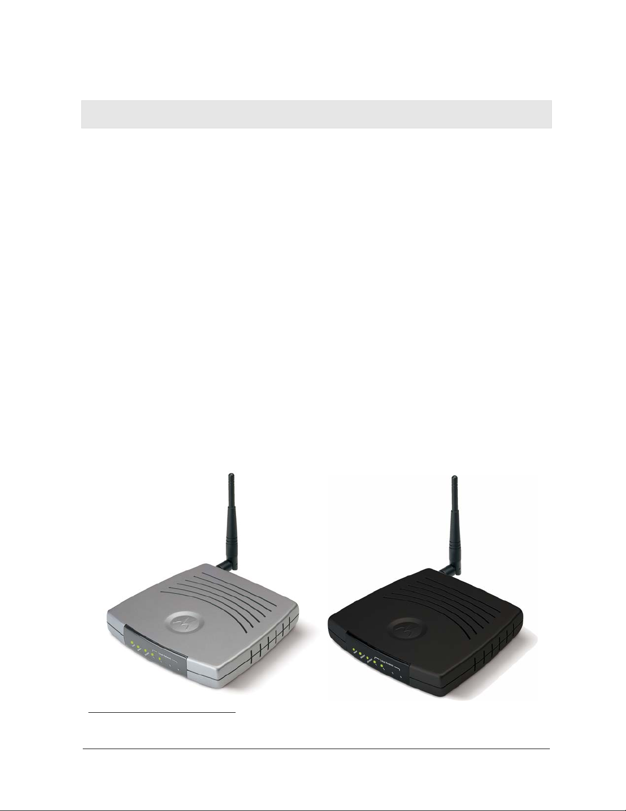
Congratulations on purchasing the Motorola® WR850GP Wireless Broadband Router or
Motorola WR850G Wireless Broadband Router.
1
The WR850 includes both an 802.11b/g wireless access point and a 4-port Ethernet router.
So it is both wireless and wired, providing the foundation for a truly customized network full
of options.
Using the WR850, you can share files, pictures, peripherals, printers and more with
everyone else on the network. By connecting a broadband modem (cable, DSL or other),
you can also share a single high speed Internet connection.
The WR850 offers both the popular 802.11b wireless standard as well as the nearly
5-times-faster 802.11g standard, providing you the ultimate in flexibility and speed. With
®
Wi-Fi
Protected Access (WPA™) included, your wireless connections are robust and
secure, giving you the security to communicate without fear that your signal might be
compromised.
The WR850GP comes loaded with Performance Enhancement technology that accelerates
your wireless network and your fun. This new technology boosts wireless performance
among compatible Motorola devices up to 35% faster than over standard 802.11g
networking.
Upgradeable firmware keeps the router’s control software up-to-date. The WR850 captures
the latest technology in a package that stays current, protects your home network, and
provides you easy home network management.
Wireless Broadband Router WR850GP Wireless Broadband Router WR850G
1
Unless otherwise stated, this User Guide will use WR850 as the generic term for both the WR850G and WR850GP
WR850 1-1
Page 8

Section 1 Overview
Your wireless router is really several products built into one router:
Wireless Access Point
– Connects your router to your laptop wirelessly and allows you to roam unfettered
– Supports a multitude of devices that operate with both 802.11g and 802.11b
wireless communication standards
– Protects your wireless communications using Wi-Fi Protected Access (WPA), Wi-Fi
TM
Protected Access version 2 (WPA2
), 802.1X, and Wired Equivalent Privacy (WEP)
security algorithms
– Supports peer-to-peer communication using built-in Wireless Distribution System
(WDS) functionality
4-port Full Duplex 10/100 Ethernet Switch and Router
– Supports wired connection of up to 4 computers or devices
– Shares a broadband Internet (cable, DSL, or other) connection with each of your
networked devices
– Enables you to form a Local Area Network (LAN)
Security and Protection
– Protects against Internet intruders with a built-in firewall
– Hides your LAN IP addresses and devices from the Internet, using Network Address
Translation (NAT) and IP and/or MAC Address filtering
– Frees you to connect to your corporate network, with Virtual Private Network (VPN)
compatibility
1-2 WR850
Page 9
Overview Section 1
Understanding Your User Guide
The User Guide is divided into the following sections:
Overview
Describes the router and its functions, the technology used, and the
recommended methods for positioning the router.
Installation
It is assumed that you will use the Installation Wizard on the CD-ROM
to set up your router. If not, refer to this section for instructions on
getting your router up and running.
After you have completed this section, your router will be active and
ready to work.
Configuration
Describes the Web-based Configuration Utility, which can be used for
advanced customization or re-configuration of the WR850.
Troubleshooting
Glossary
Details helpful solutions to common router problems.
List of terms and acronyms.
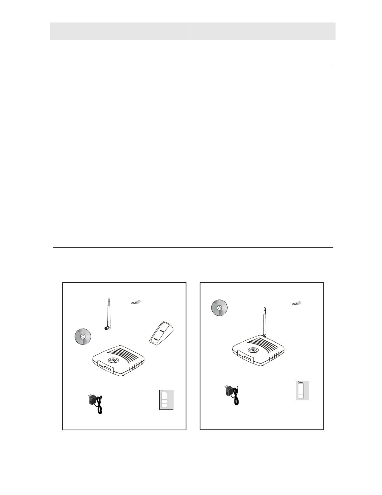
Box Contents
Your box contains the following:
WR850GP WR850G
CD-ROM
Power
Supply
Antenna
WR850GP
Ethernet
Cable
Base Station Stand
Quick Start
Guide
CD-ROM
Power
Supply
WR850G
Ethernet
Cable
Quick Start
Guide
WR850 1-3
Page 10

Section 1 Overview
Understanding Functions
Before installing your wireless router, please take a few minutes to review the wireless
networking functions described in this section.
Router
Generally, routers connect two networks together. The WR850 connects your home
network with the Internet, which can be thought of as a very large network.
The router’s firewall inspects each packet of data as it flows in from the internet before
delivering it to the appropriate PC. Network Address Translation (NAT) protects the privacy
of the IP addresses of devices on your home network, by translating them into a single
address when visible to the public internet. This is how your network remains protected and
private on the Internet.
LAN
Local Area Network. A local area network provides a full-time, high-bandwidth connection
over a limited area such as a home, building, or campus. Ethernet is the most widely used
LAN standard.
TCP/IP
Transmission Control Protocol/Internet Protocol (TCP/IP) comprises the backbone of the
Internet. IP moves packets of data between nodes while TCP verifies delivery from client to
server. Every device you hook up to your wireless router identifies itself with an IP address.
You are able to assign devices on your network with either a static or dynamically assigned
IP address.
Static IP Address
A static IP address is a fixed address that is assigned manually to a device on the network.
Static IP addresses must be unique and cannot be shared, therefore they are used in
situations where the address should never change, like print servers or PC servers.
If you are using your wireless router to share an Internet connection, your Internet Service
Provider (ISP) might have assigned you a static IP address, which you will use when
configuring your router. See Section 3: Configuration.
1-4 WR850
Page 11
Overview Section 1
Dynamic IP Address
A dynamic IP address is a temporary IP number, dynamically or randomly generated by a
DHCP server. The address lasts only as long as the server allots, usually in the space of a
day or two. When the IP address expires, the client is automatically reassigned a new IP
address, ensuring smooth communication.
If you are using your wireless router to share an Internet connection, your ISP might have
assigned you a dynamic IP address, which you use when configuring your router. See
Section 3: Configuration.
DHCP Server
A Dynamic Host Configuration Protocol (DHCP) Server assigns IP addresses to clients
connected to the router. A client is any device that can connect with your router. The client
(PC, gaming device, etc.) is automatically assigned an IP address every time a device is
added to your network, which frees you from manually assigning IP addresses.
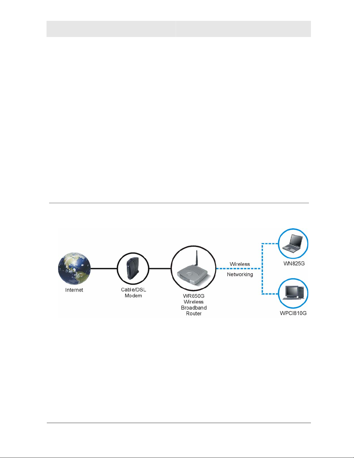
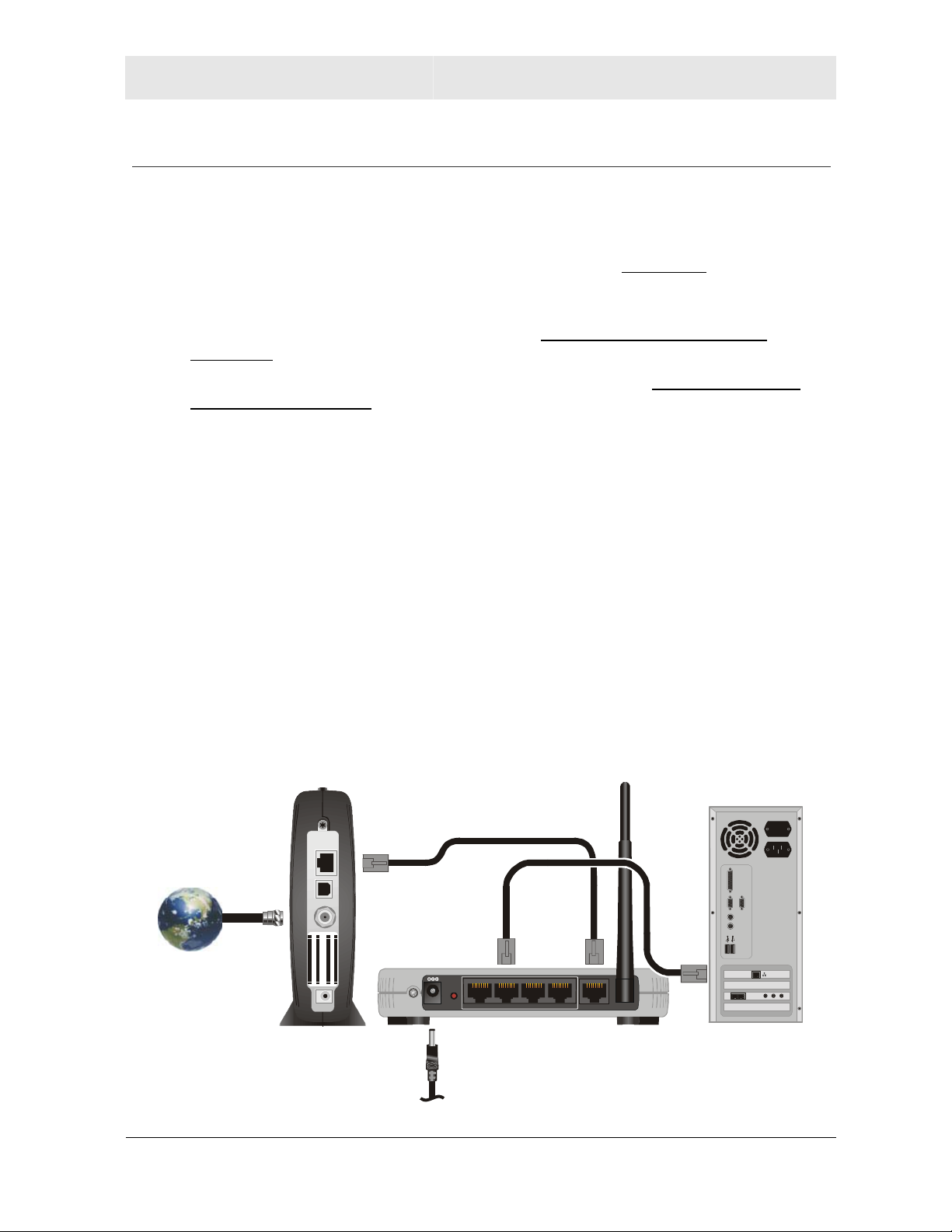
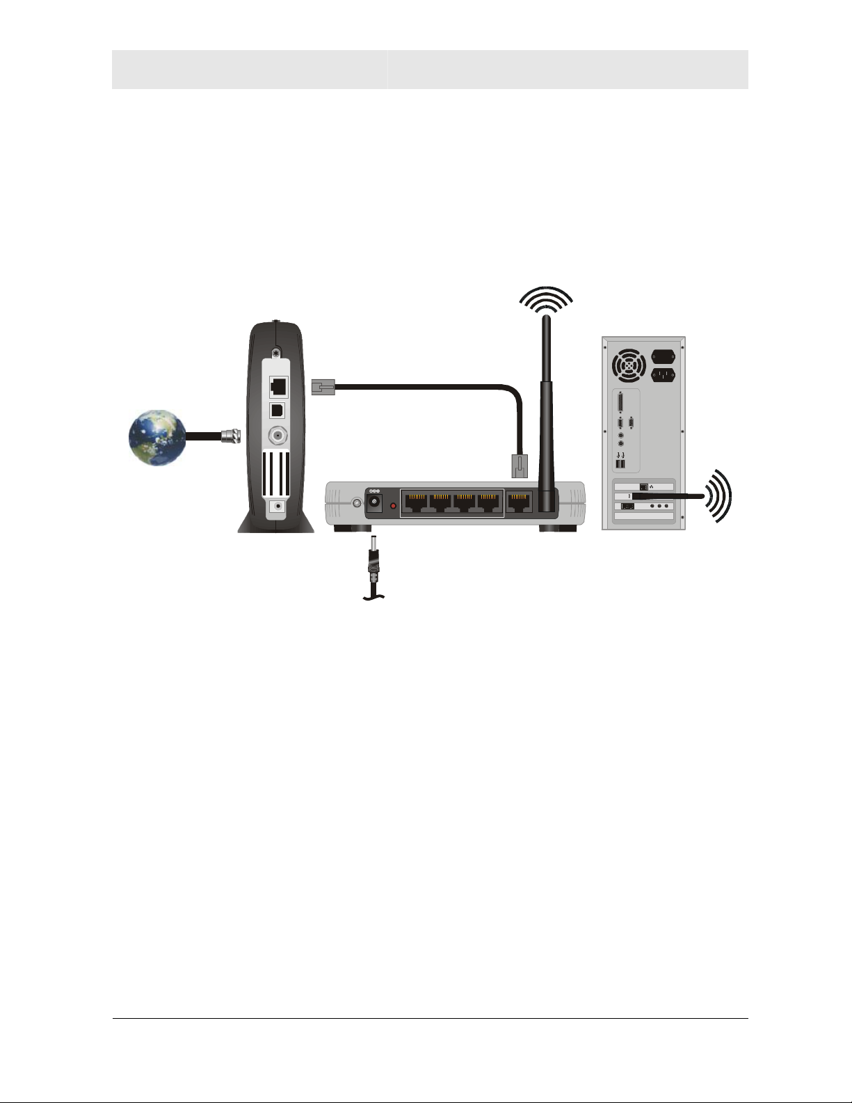
Sample Home Network Diagram
Your wireless router serves as the centerpiece of your network, allowing you to share files,
printers, and the Internet connection. A sample home network is shown below:
The Internet communicates with the modem, which in turn communicates with the router.
The router acts as the gateway to your network; it sends devices information such as
requests for Internet access, file sharing, or multiplayer games. The router controls the
information for your network, intelligently routing the information to its required destination
while at the same time protecting your network from the public domain.
WR850 1-5
Page 12
Section 1 Overview
Router Physical Description
The following sections describe the physical characteristics of your router.
For instructions on installing your router, see Section 2: Installation.
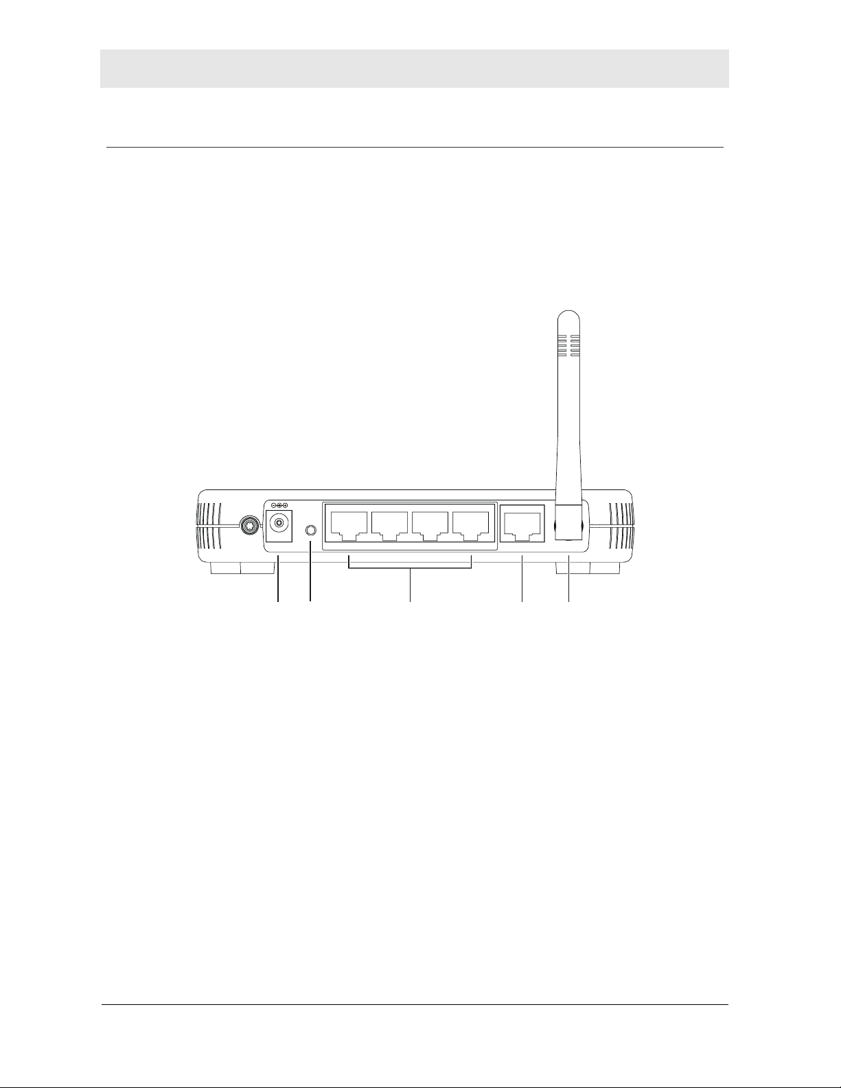
Back of Router
The following illustration shows the WR850 back panel:
Reset
Power
12 3 4 5
LAN 4 WAN3 2 1 Antenna
Feature Description
1 Power
The receptacle where you plug in the power adapter.
2 Reset
Button
Resets your router or resets the router to the default login settings.
If the router experiences trouble connecting to the Internet, briefly
press and release the Reset button to reset the router. This retains the
router’s configuration information.
To reset the router to the factory defaults, press and hold the Reset
button for more than five seconds. This clears the router’s Username,
Password, IP Address, Subnet Mask and Operation Mode. To
re-configure the router, see Section 3: Configuration.
1-6 WR850
Page 13
Overview Section 1
Feature Description
3 LAN
Ports 1-4
4 WAN
5 Antenna
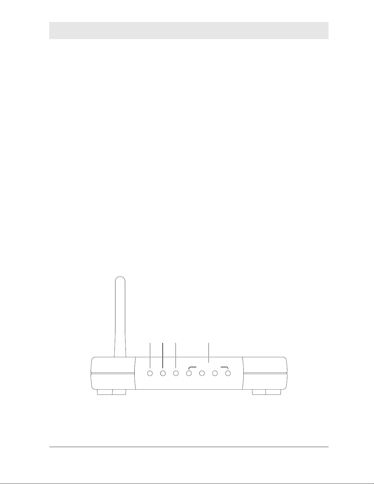
Front of Router
These four ports connect the router to your LAN or home network
using Ethernet cables. This enables communication among clients,
such as PCs or print servers, on the network. The LAN ports support
either 10-BASE-T or 100-BASE-T transmission speeds as well as
straight-through and crossover Ethernet cables.
Any of these four ports can also serve as an uplink port to other
network devices, such as another router or switch, which allows you to
extend your network.
Connect your modem to your router using this port with your supplied
Ethernet cable. This is the only port you can use for this procedure.
This enables your router to access the Internet. The port supports
10/100 Mbps as well as straight-through and crossover Ethernet
cables.
The antenna is used for wireless connections. You are able to rotate
the antenna to gain the best signal reception.
The following illustration shows the WR850 front panel:
12 3 4
Local Network
r
e
w
o
P
ss
em
e
d
l
o
re
i
M
W
2
1
The LEDs of the router indicate its operational status.
3
4
WR850 1-7
Page 14

Section 1 Overview
LED Description
LED Condition Color Status
1 Power
2 Modem
ON Green The device is powered on and operating normally.
ON Red The Power LED turns RED as soon as the reset
button is depressed. If the reset button is held
down, the LED starts to blink RED and the
router’s username, password, private LAN IP
address, private subnet mask address and
operation mode are restored to factory default
settings.
If the Power LED stays RED for longer than 5
seconds, this indicates that the firmware is
corrupted and needs to be restored.
OFF None The device is not powered on.
ON/
Blinking Amber 10BaseT link detected / active traffic present.
ON/
Blinking Green 100BaseT link detected / active traffic present.
OFF None No external Ethernet device has been attached
and detected. The Ethernet link may be down.
3 Wireless
4 LAN (x4)
ON/
Blinking Green The wireless interface is enabled / active traffic
present.
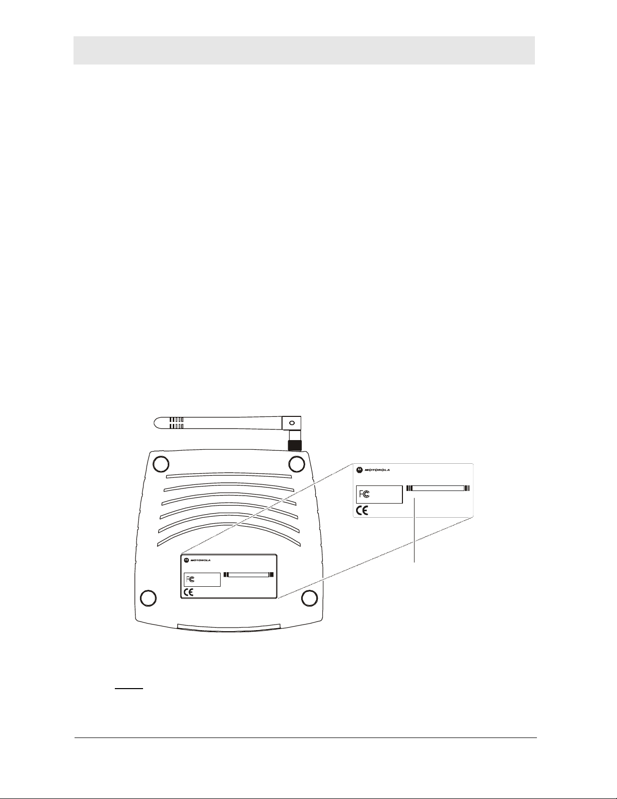
NOTE: The wireless LED does not blink on WR850G
“Version 1” hardware. You can determine
your version of hardware by looking at the
product label on the bottom of the router.
Within the box that includes the FCC logo, a
“Version 1” unit will display “MODEL:
WR850G”, while a “Version 2” unit will display
“MODEL: WR850Gv2” (see example below).
MODEL WR850G
INPUT VOLTAGE: +5VDC, 2A
FCC ID: F2N WR 850 G
MODE L: WR8 50G
Te st ed To C om pl y
FOR HOME OR OFFICE USE
With FCC Standards
PART NUMBER: AAAAAA-BBB-CC
S/N: PPPPMMYJJJSSSSSCAABBCCCC
WIRELESS MAC: AB CD EF 01 23 45
WAN MAC: AB C D EF 01 23 45
MADE IN TAIWAN
OFF None The wireless interface is not enabled by the
firmware.
ON/
ON/
Blinking
Blinking
Amber 10BaseT link detected / active traffic present
Green 100BaseT link detected / active traffic present
.
.
OFF None No external Ethernet device has been attached
and detected. The Ethernet link may be down.
1-8 WR850
Page 15

Section 2: Installation
This section will help you:
• physically install your WR850, and
• establish a first connection between a PC and the WR850.
Once this first connection is made, you can configure the WR850 to support all of the other
wired and/or wireless connections you need.
Physical Installation of the WR850
Positioning Your Router for Optimal Wireless Performance
Your wireless router uses a radio transmission technology defined by the Institute of
Electrical and Electronics Engineers (IEEE) called 802.11 Wireless Fidelity (Wi-Fi). This
standard is subdivided into distinct categories of speed and the frequency spectrum used,
designated by the lower case letter after the standard.
For example, your router supports both the ‘b’ and ‘g’ specifications. The 802.11b
specification transmits data rates up to 11 Mbps while the 802.11g specification transmits
data rates up to 54 Mbps. These are theoretical standards so your performance may vary.
The radio waves radiate out in a donut-shaped pattern. The waves travel through walls and
floors, but transmission power and distance are affected. The theoretical distance limit is
1,000 feet (305 meters), but actual throughput and distance varies.
Both standards operate in the 2.4 GHz range, meaning other electrical appliances also
might interfere with the router – televisions, radios, microwave ovens, or 2.4 GHz cordless
telephones. Therefore, positioning your router where it encounters the least interference
helps maintain a better connection.
The following lists the expected wireless range of the router. This table is only a guide and
coverage varies due to local conditions.
Data Rate Open Area Closed Area
54 Mbps
11 Mbps
5.5 Mbps
2 or 1 Mbps
To achieve the best wireless performance, review these guidelines before deciding where
to place your router:
Up to 100 ft (30m) Up to 60 ft (18m)
Up to 900 feet (275 m) Up to 160 feet (49 m)
Up to 1300 feet (396 m) Up to 200 feet (61 m)
Up to 1500 feet (457 m) Up to 300 feet (91 m)
Placing your base station in the physical center of your network is the best location
because the antenna sends out the signal in all directions.
WR850 2-1
Page 16
Section 2 Installation
Placing the router in a higher location, such as on top of a cabinet, helps disperse the
signal cleanly, especially to receiving locations on upper stories.
If possible, position your router so there is direct line of sight between the router and
your other home network devices.
Avoid placing the router next to large solid objects like computer cases, monitors, walls,
fireplaces, etc. This helps the signal penetrate more cleanly.
Other wireless devices like televisions, radios, microwaves, and 2.4 GHz cordless
telephones can interfere with the signal. Keep these devices away from the router.
Mirrors, especially silver-coated, can reduce transmission performance.
Hardware Setup
Hardware setup includes:
Antenna Installation: connecting the antenna to the router
Physical Placement: how and where you physically place your router
Electrical Connection: how to connect the power cord
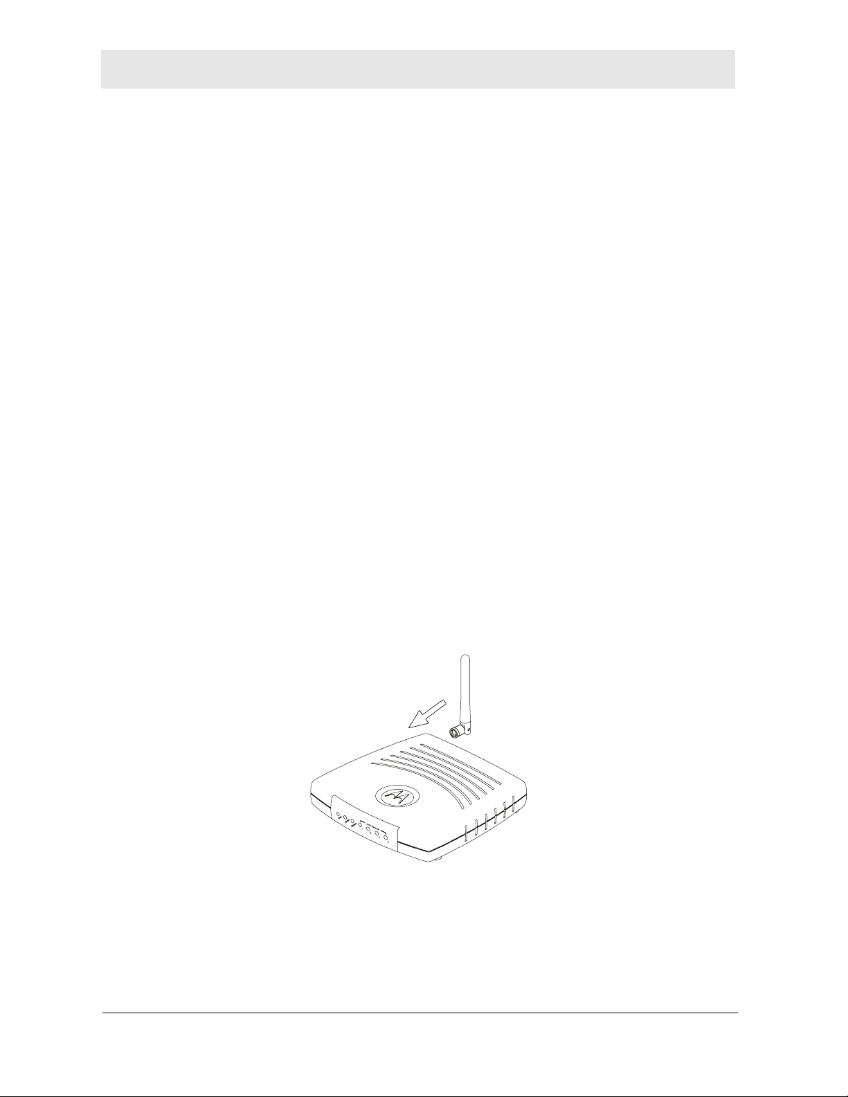
Antenna Installation
When shipped, the antenna for the WR850GP is not connected to the router. To attach the
antenna to the router:
1 Locate the antenna port on the back of the router (the threaded knob).
2 Screw the antenna connector clockwise on to the threaded knob until firmly seated. Do
not over-tighten.
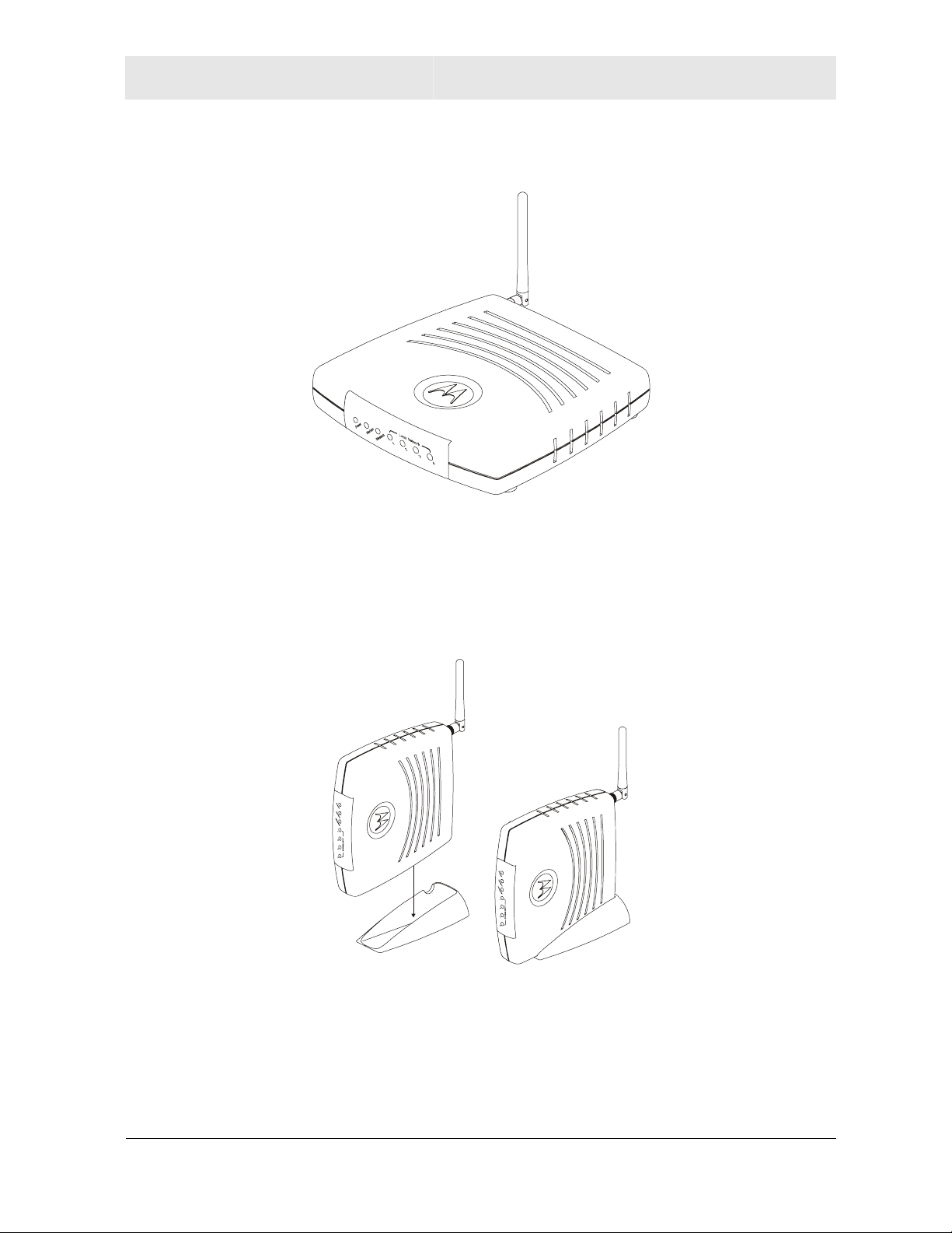
Physical Placement
For desktop use, the WR850GP can be installed either horizontally or vertically. The
WR850G can only be installed horizontally.
Either router can also be mounted on a wall.
2-2 WR850
Page 17
Installation Section 2
Horizontal Installation
1 Place the router in the desired location and follow the procedures below for connecting
and configuring the router.
Vertical Installation
(WR850GP only)
1 Insert the router into the supplied base. Ensure that the antenna’s location is on top.
The router’s foot slides snugly into a notch in the base to keep the router stable.
2 Follow the installation procedures for connecting and configuring the router.
WR850 2-3
Page 18
Section 2 Installation
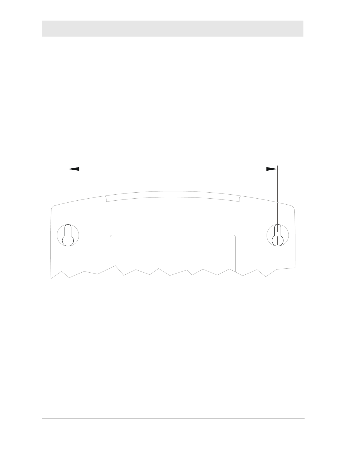
Wall Mount Installation
If you mount the router on the wall, you must:
Position the router as specified by the local or national codes governing residential or
business communications services.
Follow all local standards for installing a network interface router/network interface
device (NIU/NID).
If possible, mount the router to concrete, masonry, a wooden stud, or other solid wall
material. Use anchors when necessary; for example if you must mount the router on
drywall.
To mount your router on the wall:
1 Print the Wall Mounting Template shown on this page:
5.1”
[129.5mm]
The illustration is drawn at a one-to-one scale, which means that when printed, it
provides the exact dimensions required to mount the router.
2-4 WR850
Page 19
Installation Section 2
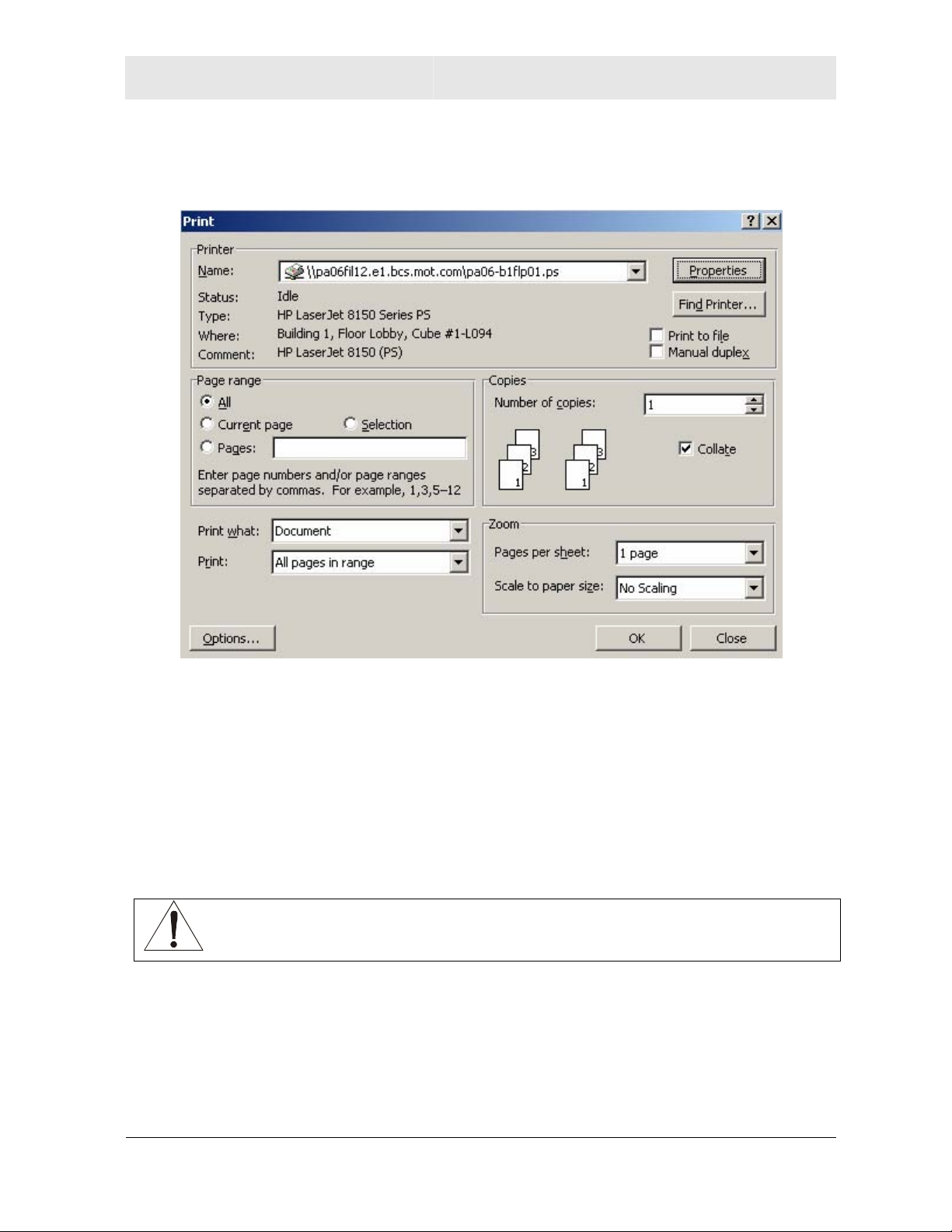
2 To print the Wall Mounting Template, click the Print icon or choose Print from the File
menu.
3 In both the Pages from and to fields, enter the page number on which the Wall
Mounting Template appears.
4 Click OK.
5 Measure the printed template with a ruler to ensure that it is the same size as the
template on page 2-3.
6 Use a center punch to mark the center of the holes on the wall.
7 On the wall, locate the marks for the mounting holes you just made.
WARNING!
Before drilling holes, check the structure for potential damage to water, gas, or
electric lines.
8 Drill the holes to a depth of at least 3.8 cm (1½ inches).
9 If necessary, seat an anchor in each hole. Use M5 x 38 mm (#10-16 x 11/2 inch) screws
with a flat underside and maximum screw head diameter of 10.5 mm to mount the
router.
WR850 2-5
Page 20
Section 2 Installation
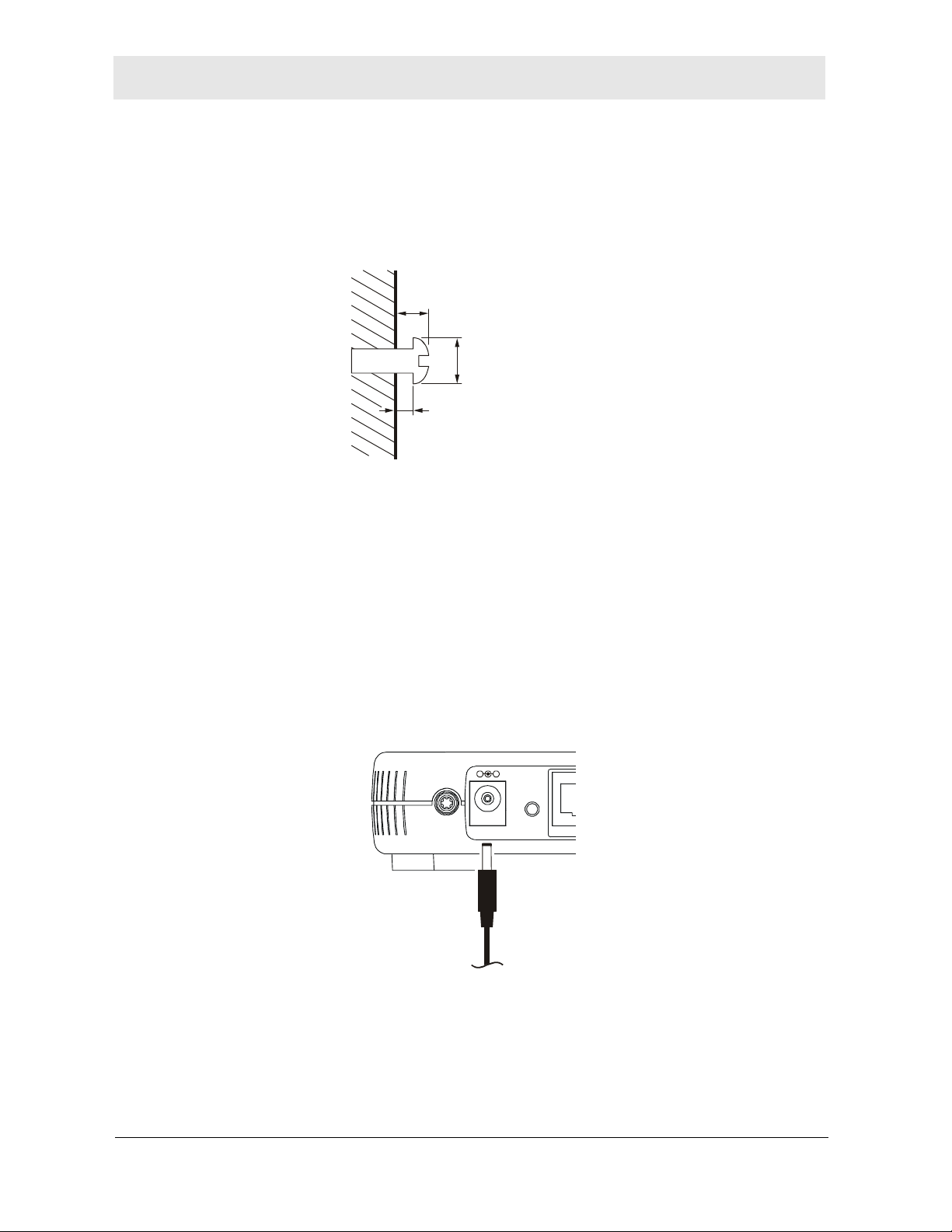
10 Using a screwdriver, turn each screw until part of it protrudes from the wall, as shown:
– There must be 4.0 mm (.16 inches) between the wall and the underside of the screw
head.
– The maximum distance from the wall to the top of the screw head is 7.6 mm (.3 in).
7.6 mm (.3 inches)
maximum
10.5 mm (.4 inches)
maximum
4.0 mm
11 Remove the two plastic feet, nearest to the LED panel, from the bottom of the router to
uncover the keyholes.
12 Place the router so the keyholes are above the mounting screws.
13 Slide the router down until it stops against the top of the keyhole opening.
14 Follow the installation procedures for connecting and configuring the router.
Electrical Connection
Your router does not have an On/Off power switch and therefore will only be powered on by
plugging in the power adapter
Reset
Power
LAN
To power
supply
1 Connect the power adapter to the router’s Power port, found on the back of the router.
2 Plug the power adapter into a grounded and surge-protected power outlet. The Power
LED on the front panel lights green when connected properly.
2-6 WR850
Page 21
Installation Section 2
A
A
Establishing Your First Connection to the WR850
Once the WR850 is placed, you can now establish your first PC connection to the WR850.
There are three ways to choose from to accomplish this:
(1) If your first connection will be a wired connection (i.e., an Ethernet cable will connect
the PC and the WR850), you can follow the step-by-step easy install process with
the included WR850 Installation Wizard CD-ROM. [recommended]
(2) If your first connection will be a wired connection, but you do not wish to use the
WR850 Installation Wizard CD-ROM, you can manually install this first wired
connection.
(3) If your first connection will be a wireless connection, you can
manually install this
first wireless connection.
Easy Install Process
Run the Installation Wizard program from the supplied CD-ROM to quickly set up your
network. Once your network is up and running, for advanced configuration, see
Section 3: Configuration.
The Installation Wizard will automatically run once you place the CD-ROM in your PC’s
CD-ROM drive. It will confirm that the antenna and electrical connections have been made,
and then lead you step-by-step through setting up your WR850 in a typical configuration as
a wired/wireless router.
Manual Install – Wired Connection
If you are manually connecting your PC with an Ethernet cable to the router, your PC must
be installed first with an Ethernet adapter. You need two Ethernet cables for this
procedure, one to connect the router to the modem and one to connect a PC to the router.
ETHERNET
USB
CABLE
HFC MAC ID: ABCDEF012345
CUSTOMER S/N:BCDFGHJKLMNP
USB CPE MAC ID:ABDCEF012345
S/N: PPPPMMYJJJSSSSSCA
BBCCCC
Reset
LAN
4
+12VDC
Power
32
WAN
1
ntenna
WR850 2-7
Page 22

Section 2 Installation
1 If you are currently running broadband to a single computer: Unplug the Ethernet cable
that runs between your modem and PC from the back of your PC and plug it into the
port labeled WAN on the back of your router.
If you are not running broadband to a single computer: Connect an Ethernet cable to
the WAN port on your router.
2 Connect the other end of the same cable to your cable or DSL modem. You have now
connected the router to the modem. It will be necessary to restart your cable or DSL
modem after making this connection.
3 To connect the PC to the router, use a second Ethernet cable and connect it to the
Ethernet port on your PC.
4 Connect the other end of the same cable into one of the LAN ports on your router. You
have now connected your PC to the router.
5 Your PC’s Ethernet adapter may need to be configured to work with the WR850.
By default, the WR850 has a LAN IP Address of 192.168.10.1, and dynamically assigns
an IP Address to connected devices. The PC will not communicate properly with the
WR850 if the Ethernet adapter is not configured either:
(a) to accept a dynamic IP Address, or
(b) with a compatible static IP Address (i.e., 192.168.10.x, where x is a number
between 2 and 254).
To make any necessary adjustments to your PC’s Ethernet Adapter, you can follow the
instructions in this section under Configuring Computers to Communicate with the
WR850.
NOTE: You can make wired connections between the WR850 and other device s by
repeating Steps 3, 4, and 5 with each of those devices.
6 Once the PC is communicating with the WR850, you can proceed to Section 3:
Configuration to access the built-in Web-based Configuration Utility and configure the
WR850:
•
For a typical WR850 configuration as a wired/wireless router, review and adjust as
necessary only those configuration options designated as “commonly used” or
“recommended”. These fields are labeled with white letters.
For advanced WR850 configuration, review and adjust any and all configuration
•
options as desired. Field codes requiring more advanced knowledge to configure
are labeled with black letters.
Manual Install – Wireless Connection
WARNING!
When first configuring your router, it is recommended that you have an Ethernet
cable connected to the router. Performing the INITIAL configuration using a
wireless connection is not secure and is not recommended.
After you have finished the initial configuration of the router, your connection will
be secure and you can safely use either a wired or wireless connection.
2-8 WR850
Page 23
Installation Section 2
A
A
If you are connecting your client wirelessly to the router, you can use the Motorola
WPCI810G or WPCI810GP, a wireless PCI adapter for your desktop PC. If you have a
laptop, the Motorola WN825G or WN825GP wireless PC card adapter provides access. A
Motorola WU830G wireless USB adapter can also provide access for desktops or laptops.
The WPCI810G, WN825G, and WU830G support the Windows
Windows XP
None of these adapters support Windows
™
operating systems. The WPCI810GP and WN825GP support Windows 2000 and XP only.
ETHERNET
USB
CABLE
USB CPE MAC ID:ABDCEF012345
S/N: PPPP MMYJJJ SSSSS CA
HFC MAC ID: ABCDEF012345
CUSTOMER S/N:BCDFGHJKLMNP
BBCCCC
+12VDC
®
95, Windows® 98, or Windows NT®.
Reset
LAN 4 WAN321
Power
®
98SE, Windows Me®, Windows® 2000, and
ntenna
1 If you are currently running broadband to a single computer, unplug the Ethernet cable
that runs between your modem and PC from the back of your PC and plug it into the
port labeled WAN on the back of your router.
If you are not running broadband to a single computer, connect an Ethernet cable to the
WAN port on your router.
2 Connect the other end of the same cable to your cable or DSL modem. You have now
connected the router to the modem. It will be necessary to restart your cable or DSL
modem after making this connection.
WR850 2-9
Page 24
Section 2 Installation
3 Your PC’s wireless adapter may need to be configured to work with the WR850.
By default, the WR850 has a LAN IP Address of 192.168.10.1, and dynamically assigns
an IP Address to connected devices. The PC will not communicate properly with the
WR850 if the wireless adapter is not configured either:
(a) to accept a dynamic IP Address, or
(b) with a compatible static IP Address (i.e., 192.168.10.x, where x is a number
between 2 and 254).
To make any necessary adjustments to your PC’s wireless adapter, you can follow the
instructions in this section under Configuring Computers to Communicate with the
WR850.
4 To connect the PC to the WR850 through a wireless connection, use your PC’s wireless
adapter utility to verify:
(a) the selection of the SSID (Service Set Identifier) of the WR850, which by default
is set to motorolaABCDEF012345, where the final 12 characters represent the
WR850’s Wireless MAC address (see the image below to identify the WR850
Wireless MAC address from the product label),
(b) that authentication is set to Open, since the WR850 by default has no wireless
authentication enabled, and
(c) that no encryption is enabled, since the WR850 by default has no wireless
encryption enabled.
MODEL WR85 0G
PART NUMBER: AAAAAA-BBB-CC
WAN MAC: AB CD EF 01 23 45
MADE IN TAIWAN
INPUT VOLTAGE: +5VDC, 2A
FCC ID: F2N WR850G
MODEL: WR850G
Test e d To Com pl y
With FCC Standards
FOR HOME OR OFFICE USE
MODEL WR850G
PART NUMBER: AAAAAA-BBB-CC
S/N: PPPPMMYJJJSSSSSCAABBCCCC
WIRELESS MAC: AB CD EF 01 23 45
WAN MAC: AB CD EF 01 23 45
MADE IN TAIWAN
INPUT VOLTAGE: +5VDC, 2A
FCC ID: F2NWR850G
MODEL: WR 850G
With FCC Standards
FOR HOME OR OFFICE USE
Test ed To Comp ly
S/N: PPPPMMYJJJSSSSSCAABBCCCC
WIRELESS MAC: AB CD EF 01 23 45
Wireless MAC address
Refer to your wireless adapter’s documentation for instructions on how to review and
adjust these settings.
NOTE: You can make wireless connections between the WR850 and other d evices by
repeating Steps 3 and 4 with each of those devices, but it is recommended to wait
until after securing your wireless network to do so.
2-10 WR850
Page 25

Installation Section 2
5 Once the PC is communicating with the WR850, you can proceed to Section 3:
Configuration to access the built-in Web-based Configuration Utility and configure the
WR850:
•
For a typical WR850 configuration as a wired/wireless router, review and adjust as
necessary only those configuration options designated as “commonly used” or
“recommended”. These fields are labeled with white letters.
For advanced WR850 configuration, review and adjust any and all configuration
•
options as desired. Field codes requiring more advanced knowledge to configure
are labeled with black letters.
In either case, it is recommended that you first use the Web-based Configuration
Utility to establish security measures on your wireless network, and re-connect
securely to the WR850, prior to making any other changes to the WR850.
Configuring Computers to Communicate with the WR850
Each computer that will be part of your network needs to communicate with the router. To
do this, you may need to configure each PC’s network settings to automatically obtain an IP
address.
This section includes information on configuring computers with the following operating
systems:
®
Windows
Windows Me
Windows
Windows XP
98SE
®
®
2000
™
Determine the operating system for each computer you will include in your wireless network
and follow the steps to configure the network settings for that PC.
WR850 2-11
Page 26
Section 2 Installation
Configuring Windows 98SE and ME
1 Click Start.
2 Select Settings > Control Panel.
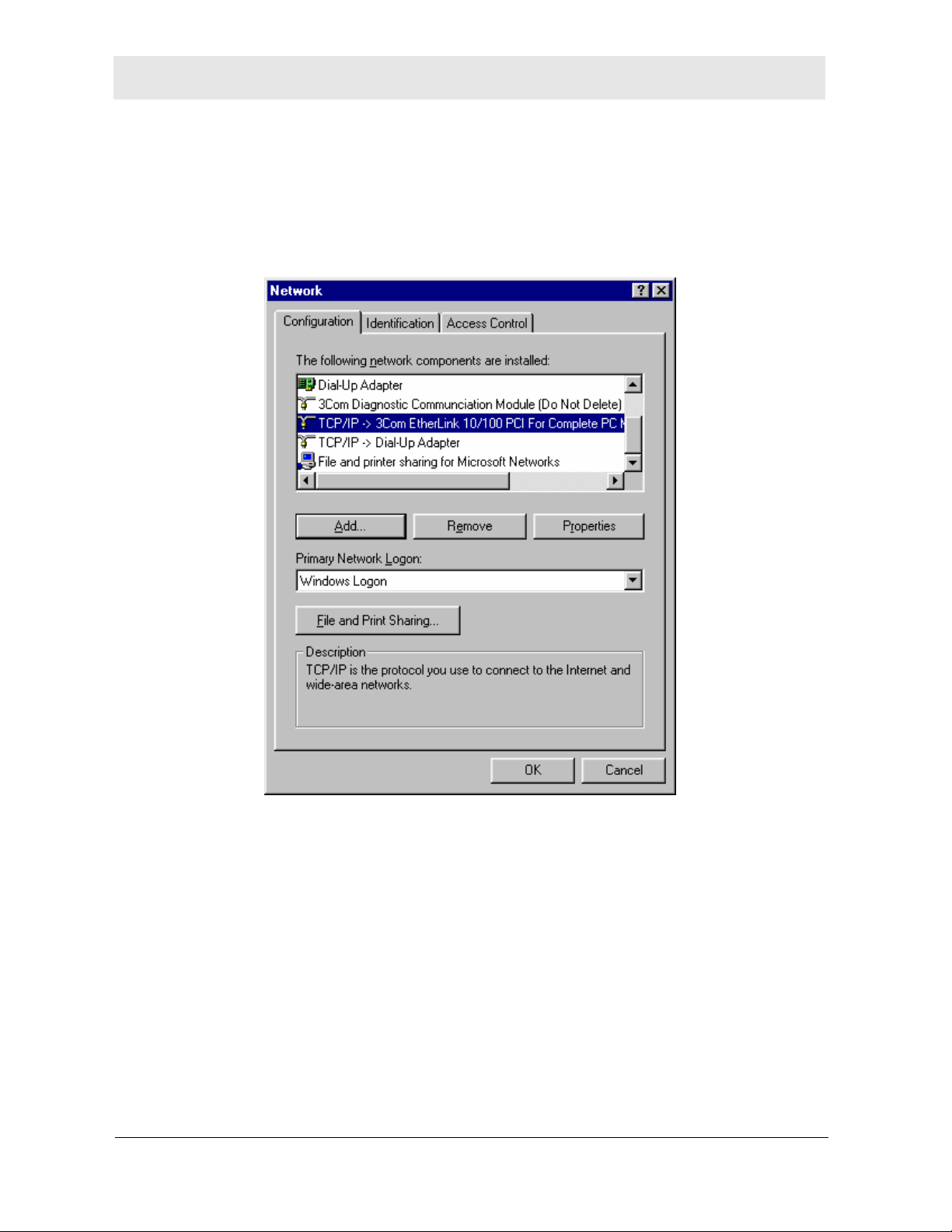
3 Double-click Network. The Network window is displayed.
4 On the Configuration tab, select the TCP/IP line the for the appropriate wired or wireless
Ethernet adapter on your PC. There may be multiple adapters installed – choose only
the one that is configured for your adapter. In the example above, a 3Com Ethernet
adapter card is installed and is the appropriate choice.
2-12 WR850
Page 27
Installation Section 2
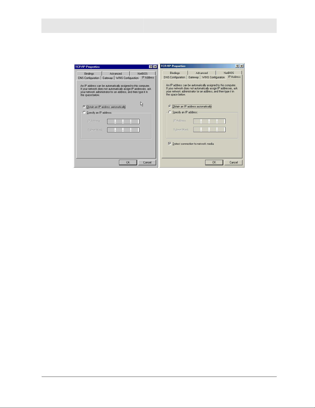
5 Click Properties. The TCP/IP Properties window is displayed.
Windows 98SE Windows ME
6 Click the IP Address tab.
7 Select Obtain an IP address automatically.
8 Click OK.
9 Click the Gateway tab and confirm that the Installed Gateway field is blank.
10 Click OK twice. Windows may ask for the Windows Installation disk. First check to see if
the installation files are installed at c:\windows\options\cabs. Otherwise, load your
Windows CD and follow the prompts.
11 Restart your computer to save your settings.
WR850 2-13
Page 28
Section 2 Installation
Configuring Windows 2000
1 Click Start.
2 Select Settings.
3 Select Control Panel.
4 Double-click Network and Dial-Up Connections.
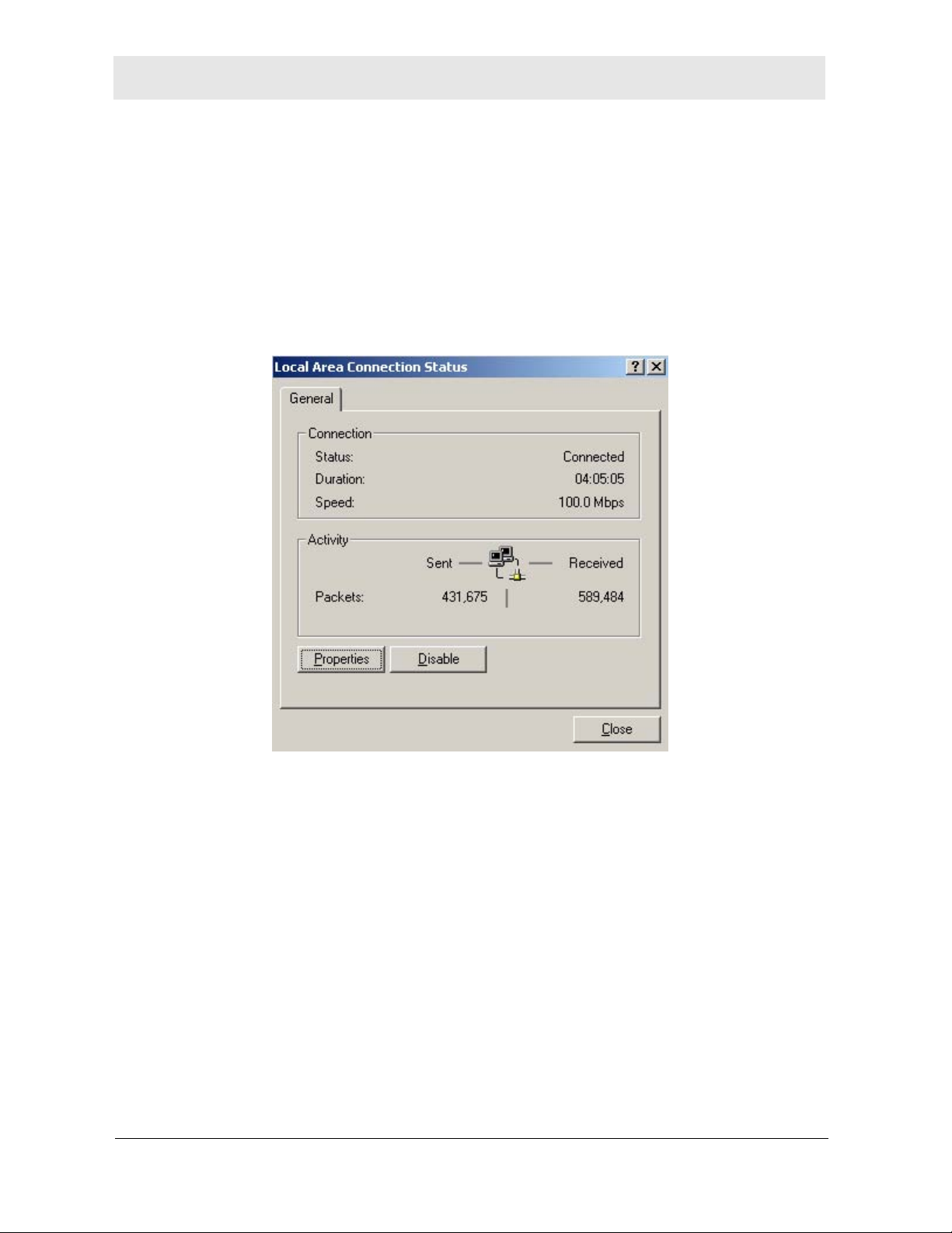
5 Double-click the Local Area Connection appropriate for your wired or wireless
Ethernet adapter.
6 Click Properties.
2-14 WR850
Page 29
Installation Section 2
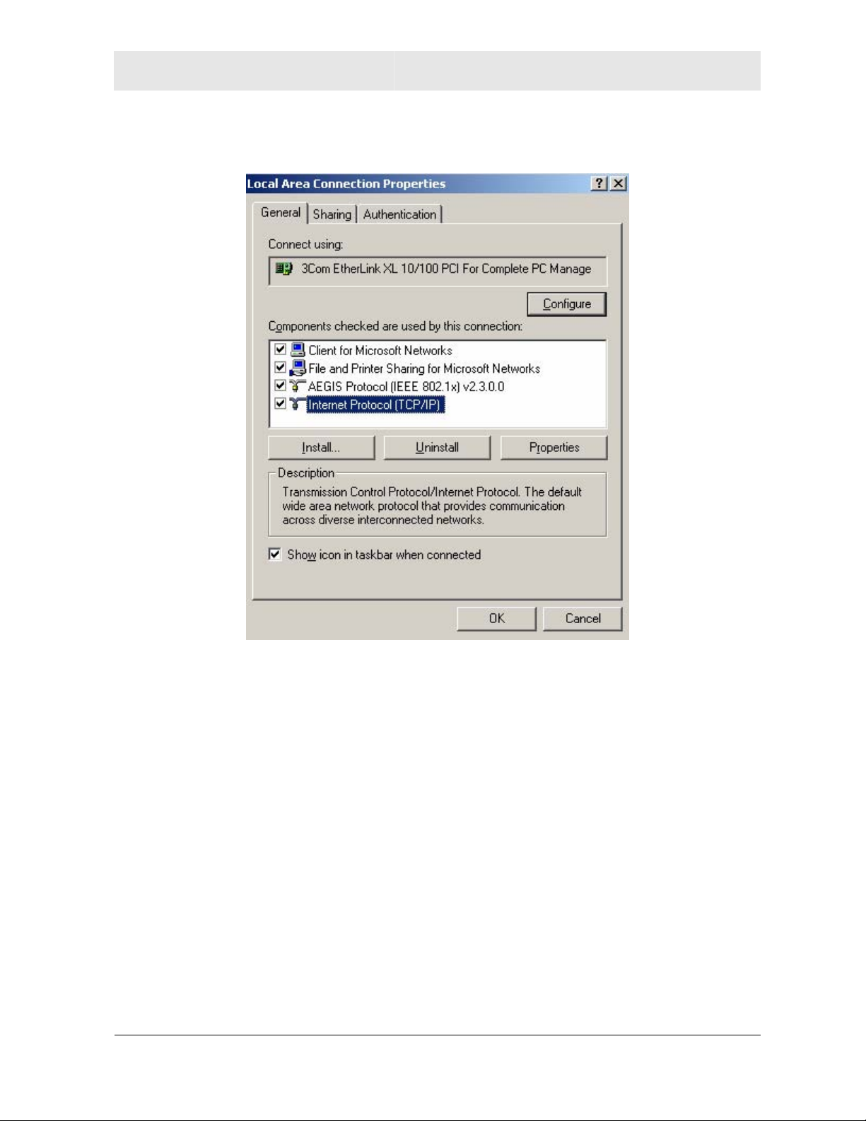
The Local Area Properties window is displayed.
7 Ensure the box next to Internet Protocol (TCP/IP) is selected.
8 Click to highlight Internet Protocol (TCP/IP) and click Properties.
WR850 2-15
Page 30
Section 2 Installation
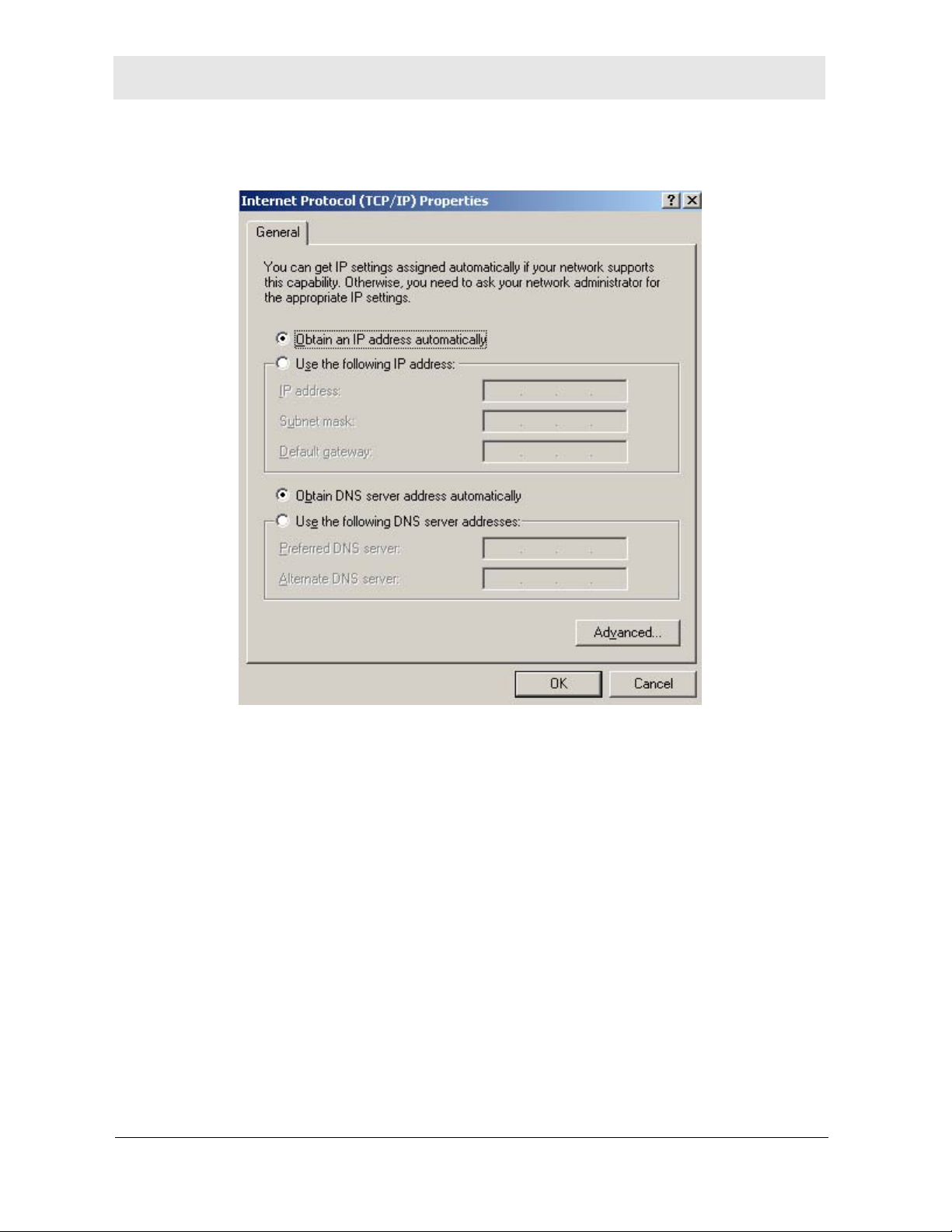
The Internet Protocol (TCP/IP) Properties window is displayed.
9 Select Obtain an IP address automatically. Click OK twice to exit and save your
settings.
10 Restart your computer to save your settings.
2-16 WR850
Page 31

Installation Section 2
Configuring Windows XP
This configuration assumes you have retained the default interface for Windows XP. If you
are running the ‘Classic’ interface, please follow the instructions for Windows 2000.
1 Click Start.
2 Select Settings.
3 Select Control Panel.
4 Double-click Network and Dial-Up Connections.
5 Double-click the Local Area Connection appropriate for your wired or wireless
Ethernet adapter.
6 Click Properties.
WR850 2-17
Page 32

Section 2 Installation
The Local Area Properties window is displayed.
7 Ensure the box next to Internet Protocol (TCP/IP) is selected.
8 Click to highlight Internet Protocol (TCP/IP) and click Properties.
2-18 WR850
Page 33

Installation Section 2
The Internet Protocol (TCP/IP) Properties window is displayed.
9 Click Obtain an IP address automatically. Click OK twice to exit and save your
settings.
WR850 2-19
Page 34

Section 3: Configuration
This section describes how to use the Web-based Configuration Utility built into your
WR850 Wireless Broadband Router. This utility allows you to customize the WR850 to
meet your specific needs.
The Web-based Configuration Utility provides several pages of configuration options.
These configuration options are factory set to default values, based on the typical use of the
WR850 as a wired/wireless router. When you login to the utility for the first time, you will
find all options set to these factory defaults, unless you have already made changes by
running the WR850 Installation Wizard CD-ROM.
In fact, if you have already used the WR850 Installation Wizard CD-ROM to initially set up
your router, in many cases you will not need to adjust any other configuration options.
Where adjustments of configuration options are required, additional online help is provided
through “rollover” descriptions. While using the Web-based Configuration Utility, as you roll
your mouse cursor over the name of any configuration option, a brief description of that
option will be displayed.
NOTE: The screenshots shown are intended for reference only; your version of firmware
may differ slightly.
WR850 3-1
Page 35

Section 3 Configuration
Accessing the Web-Based Configuration Utility
Logging In
1 Once the router is connected, open your web browser. In the URL field enter
http://192.168.10.1 (the router’s default IP address). Press the Enter key.
The login window will appear (the WR850GP login window is shown in the example
below):
2 Enter the User Name. The default factory setting is admin.
3 Enter the Password. The default factory setting is motorola.
Once you have logged in, for security reasons you should change the User ID and Password. See below.
4 Click OK to enter the Web-based Configuration Utility.
The BASIC configuration page will appear when entering the Web-based Configuration
Utility.
3-2 WR850
Page 36

Configuration Section 3
Overview of Configuration Pages
Navigation Between Pages
The Web-based Configuration Utility is made up of nine configuration pages, each with
configuration options tied to different functions of the WR850. A “selection bar,” listing all of
these configuration pages, appears at the top of each configuration page.
Figure 3-2 Configuration Page Selection Bar
You can access any page by moving the cursor over a specific configuration page title in
the selection bar, and clicking on the page title.
These configuration pages are as follows:
BASIC:
WR850.
LAN (LOCAL AREA NETWORK):
support connections to devices within your local home or small office network.
WAN (WIDE AREA NETWORK): This page allows you to configure your WR850 to
support connections to broadband services.
STATUS: This page displays information about the status of your WR850.
FILTERS: This page allows you to configure two types of filters, allowing you to block
undesired use of your broadband connection. One potential use of these filters is to set
parental controls on the use of the Internet.
ROUTING:
needed to allow specific clients on your local network to run and share certain programs
that use the Internet
WIRELESS: This page allows you to configure your wireless network.
SECURITY: This page allows you to configure security features to protect information
shared over wireless connections.
FIRMWARE: This page allows you to upgrade the firmware of your WR850.
On each configuration page, the most commonly used configuration options are highlighted
in white for easy reference. What follows are page-by-page descriptions of the
configuration options available.
This page allows you to configure basic access and control features of your
This page allows you to configure your WR850 to
This page allows you to configure port forwarding and triggering rules, as
.
WR850 3-3
Page 37

Section 3 Configuration
The BASIC Configuration Page
This page allows you to configure basic access and control features of your WR850. It is
the first page you see
Figure 3-1 BASIC Page
when entering the Web-based Configuration Utility.
BASIC Page – Commonly Used Configuration Options
The following configuration options are highlighted in white on the BASIC Page for easy
reference. These fields are the most commonly used or adjusted in supporting typical uses
of the WR850 as a wired/wireless router.
The rest of the configuration options are provided primarily for advanced users.
3-4 WR850
Page 38

Configuration Section 3
Field Description
Configuration
Login
Username:
Configuration
Login
Password:
NOTE: Once you have logged in, for security reasons you should change the default User Name
and Password. If necessary, the default settings can be reset, either by clicking the Restore
Factory Configuration button at the bottom of the BASIC Page (which will reset all options to
factory defaults) or by using the Reset button on the back of the WR850 (which, as referenced in
Section 1 of this User Guide, will reset only a select number of options).
If you wish, you can disable access control by leaving both the Configuration Login Usern ame
and Configuration Login Password blank, but this is
Time Zone:
Sets your user name to access this Web-based Configuration Utility.
FACTORY DEFAULT: admin
Sets your password to access this Web-based Configuration Utility.
FACTORY DEFAULT: motorola
not recommended.
Sets the time zone for your location from among the following:
Kwajalein Atlantic Time (Canada)
Brazil West
Midway Island,
Samoa
Hawaii Brazil East, Greenland Bangladesh, Russia
Alaska Mid-Atlantic Thailand, Russia
Guyana Pakistan, Russia
Armenia
Pacific Time (USA,
Canada)
Arizona Gambia, Liberia,
Mountain Time (USA,
Canada)
Mexico Tunisia Guam, Russia
Central Time (USA,
Canada)
Indiana East,
Colombia, Panama
Eastern Time (USA,
Canada)
Bolivia, Venezuela Iraq, Jordan, Kuwait New Zealand
Azores China, Hong Kong,
Australia Western
Singapore, Taiwan,
Morocco
England Japan, Korea
France, Germany,
Sweden, Finland
South Africa Solomon Islands
Greece, Ukraine,
Romania, Turkey
Russia
Australia
Fiji
FACTORY DEFAULT: Eastern Time (USA & Canada)
WR850 3-5
Page 39

Section 3 Configuration
BASIC Page – All Configuration Options
Options related to: CONTROLLING ACCESS TO THE CONFIGURATION UTILITY
Field Description
Configuration
Login Username:
Configuration
Login Password:
NOTE: Once you have logged in, for security reasons you should change the default User Name
and Password. If necessary, the default settings can be reset, either by clicking the Restore
Factory Configuration button at the bottom of the BASIC Page (which will reset all options to
factory defaults), or by using the Reset button on the back of the WR850 (which, as referenced in
Section 1 of this User Guide, will reset only a select number of options).
If you wish, you can disable access control by leaving both the Configuration Login Usern ame
and Configuration Login Password blank, but this is
Remote Login
Port:
(ADVANCED)
Sets your user name to access this Web-based Configuration Utility.
FACTORY DEFAULT: admin
Sets your password to access this Web-based Configuration Utility.
FACTORY DEFAULT: motorola
not recommended.
Enables access to the Web-based Configuration Utility while away
from your home or office, through your broadband connection. An
HTTP port (such as 8080) must be provided to enable remote
access. Leave this field blank to disable remote access.
FACTORY DEFAULT: (blank)
Options related to: ENABLING PRIMARY ROUTER FUNCTIONS
Field Description
Operation Mode:
(ADVANCED)
Enables the primary router functions of the WR850. These router
functions include:
• Routing data in your local network using IP addresses of the
connected devices, allowing the IP address for your
broadband connection to be shared among those devices.
This is called Network Address Translation (NAT).
(continued on next page)
3-6 WR850
Page 40

Configuration Section 3
Field Description
Operation Mode:
(continued)
• Dynamically assigning IP addresses to devices on your local
network, simplifying network set-up, using the Dynamic Host
Configuration Protocol (DHCP).
This is the WR850’s built-in local area network DHCP server
(which is configured on the LAN Page).
• Routing and/or filtering data based on the protocol used
and/or its content, protecting your broadband connection and
your local network from undesired access.
This is the WR850’s built-in firewall (which can be configured
with specific filters on the FILTERS Page, and with specific
routing “rules” on the ROUTING Page).
If all of these router functions are disabled, the WR850 simply
operates as a combination of a wireless access point and a wired
5-port Ethernet switch (the physical port labeled “WAN” becomes the
fifth “switched” port, along with the four “LAN” ports).
With router functions disabled, all WR850 configuration options that
use the
IP addresses of local network devices are disabled (with any
entries into those fields ignored). However, all WR850 configuration
options that use
Media Access Control (MAC) addresses of local
network devices – physical addresses uniquely assigned by
manufacturers to any network device -- are still available.
Firewall:
(ADVANCED)
• Selecting Router enables router functions.
• Selecting Access Point disables router functions.
NOTE: If you wish to enable some router functions and not all, select
Router and then disable specific router functions via their
respective configuration options that follow.
For example, if you wish to use the firewall but have no need for
the DHCP server, select Router here and then disable DHCP
Server on the LAN Page.
FACTORY DEFAULT: Router
Enables the built-in firewall, to protect your router and local network
from unauthorized access from the Internet.
• Selecting Enabled engages the built-in firewall.
• Selecting Disabled disengages the built-in firewall.
NOTE: It is recommended that the firewall be disabled only if you are
using alternative firewall protection software.
NOTE: Firewall is greyed out to Disabled if Operation Mode (above) is
set to Access Point.
FACTORY DEFAULT: Enabled
WR850 3-7
Page 41

Section 3 Configuration
Field Description
UPnP:
(ADVANCED)
Enables Universal Plug and Play (UPnP) operation, a feature
required by some software programs to automatically configure your
router for compatibility.
• Selecting Enabled allows these software programs to
automatically manage compatibility with the router, without
additional user configuration.
• Selecting Disabled does not allow these software programs
to automatically manage compatibility with the router.
NOTE: UPnP requires router functions to be enabled. This setting will
only be used if Operation Mode (above) is set to Router.
FACTORY DEFAULT: Enabled
Options related to: ENABLING TIME-RELATED FUNCTIONS
Field Description
Local Time
(DISPLAY ONLY)
Time Zone:
Auto Adjust for
Daylight Saving
Time
Shows the day, month, year and local time (in that order), as
maintained by the WR850.
Sets the time zone for your location. See drop-down listing for
available time zones.
FACTORY DEFAULT: Eastern Time (USA & Canada)
Enables automatic adjustment of local time for Daylight Saving Time.
Select Disabled if Daylight Saving Time is not observed in your
area.
FACTORY DEFAULT: Enabled
3-8 WR850
Page 42

Configuration Section 3
Internet Time
Server
Addresses:
The WR850 can use an Internet time server to maintain the integrity
of time-dependent router functions (logging, filtering, etc.).
Motorola sponsors two Internet time servers; their IP addresses are
listed in the first two address fields, making them the first two time
(ADVANCED)
servers used.
You may add one IP address for an additional Internet time server.
This would serve as a back-up resource, if for any reason the
Motorola servers are temporarily unavailable.
FACTORY DEFAULT: Motorola time servers are listed in fields 1 and 2;
field 3 is blank.
Options related to: LOGGING WR850 ACTIVITY
Field Description
Event Log
Destination
Address:
(ADVANCED)
Sets an IP address as the destination for the posting of router logs.
Logs are posted in a “syslog” format; you can read them using a
Syslog Daemon (e.g., the Kiwi Syslog Daemon, etc.), which can
often be found offered as freeware on the Internet.
Connection
Logging:
(ADVANCED)
Leave this field blank to set the STATUS Page (within this Webbased Configuration Utility) as the only destination for router logs.
FACTORY DEFAULT: (blank)
Sets the types of router connections to be logged.
• Selecting Accepted will only log accepted connections.
• Selecting Denied will only log denied connections.
• Selecting Disabled will log neither accepted nor denied
connections.
• Selecting Both will log both accepted and denied
connections.
FACTORY DEFAULT: Disabled
WR850 3-9
Page 43

Section 3 Configuration
BASIC Page Action Buttons
At the bottom of the BASIC Page, you will see four click-able buttons to process any
desired changes to the configuration options.
Button Purpose
Apply
This button allows you to apply the settings you have selected for
BASIC Page configuration options.
When you click the Apply button, you will see an “Applying Changes”
page that shows the status of validating and committing the new
selections that have been made.
If no errors were made in the new selections, the prior selections
(including any default settings) will be overridden with your new
selections. If errors were made in the new selections, you can return
to the BASIC Page to correct and re-apply them.
NOTE: Applying changes on the BASIC Page will reboot your WR850.
During a reboot, you may temporarily lose your connection to the
Web-based Configuration Utility.
Cancel
Cancels all changes you have made on the BASIC Page, reverting
the page to its previously saved configuration.
Any new selections will be deleted and not be applied.
Restart
Restarts your WR850. This can be used to reset WR850 logs and
refresh information.
Restore
Factory
Configuration
This button resets all configuration options to their original factory
default settings.
NOTE: This button will reset configuration options on all pages to
defaults, not just the options on the BASIC Page.
3-10 WR850
Page 44

Configuration Section 3
The LAN (Local Area Network) Configuration Page
This page allows you to configure your WR850 to support connections to devices within
your local home or small office network, or LAN. This can include devices connected via
the WR850 wired LAN ports, or via the built-in wireless access point.
Figure 3-4 Local Area Network (LAN) Page
LAN Page – Commonly Used Configuration Options
None of the configuration options on the LAN Page typically require any adjustment from
factory defaults, to support most typical uses of the WR850 as a wired/wireless router.
Therefore, none of the configuration options on the LAN Page are highlighted in white.
LAN Page configuration options are provided primarily for advanced users.
WR850 3-11
Page 45

Section 3 Configuration
LAN Page – All Configuration Options
Options related to: SELECTING THE WR850 LOCAL AREA NETWORK PROTOCOL
Field Description
MAC Address:
(DISPLAY ONLY)
Protocol:
(ADVANCED)
IP Address:
(ADVANCED)
Shows the Media Access Control (MAC) address of the WR850 LAN
connections. This is the physical address of these LAN connections.
Sets the method by which an IP address is assigned to the WR850’s
LAN connections.
• Selecting Static requires that a unique and permanent IP
address be assigned, in the IP Address field just below.
• Selecting DHCP assumes that a Dynamic Host Configuration
Protocol server is on your LAN and can assign the WR850
an IP address. You will want to disable the WR850 DHCP
server below.
NOTE: If Operation Mode on the BASIC Page is set to Router, this field
is set to Static (and you will not be able to select DHCP).
FACTORY DEFAULT: Static
Sets the IP address for the WR850 LAN connections, when the
Protocol field is set to Static.
NOTE: Changing this IP Address will change the address at which you
access the Web-based Configuration Utility.
NOTE: Changing this IP Address should be coordinated with the IP
addresses you assign to devices that will connect to the WR850.
NOTE: If Protocol (above) is set to DHCP, this field will be greyed out,
and any data entered will not be used.
FACTORY DEFAULT: 192.168.10.1
Subnet Mask:
(ADVANCED)
Sets the subnet mask for the WR850 LAN connections, when the
Protocol field is set to Static. The subnet mask is used to divide your
LAN into multiple “subnets.”
NOTE: If Protocol (above) is set to DHCP, this field will be greyed out,
and any data entered will not be used.
FACTORY DEFAULT: 255.255.255.0
3-12 WR850
Page 46

Configuration Section 3
Field Description
Default
Gateway:
(ADVANCED)
Sets the IP address of the default gateway for the WR850
connections, when the Protocol field is set to Static.
The default gateway is set by default to be the WR850 (i.e., the
factory default IP address matches that of the WR850).
NOTE: If Protocol (above) is set to DHCP, this field will be greyed out,
and any data entered will not be used.
FACTORY DEFAULT: 192.168.10.1
Options related to: ENABLING THE WR850 BUILT-IN DHCP SERVER
Field Description
DHCP Server:
(ADVANCED)
Sets the method by which IP addresses are assigned to devices that
interface with the WR850 via the LAN connections (or “clients”).
• Selecting Enabled engages the Dynamic Host Configuration
Protocol (DHCP) server, which can dynamically assign (or
“lease”) IP addresses to clients.
• Selecting Disabled disengages the DHCP server, requiring
that you manually assign unique and permanent (or “static”)
IP addresses to clients.
NOTE: The built-in DHCP Server is a router function. Therefore, this
field, and the related DHCP Server fields below, are disabled or
ignored if the Operation Mode on the BASIC Page is set to
Access Point.
NOTE: You will need to disable the DHCP Server, and assign static IP
addresses, if you wish to use features on the ROUTING Page.
FACTORY DEFAULT: Enabled
DHCP Starting
IP Address:
(ADVANCED)
Sets the start of the IP address range that the DHCP server will
lease to clients.
NOTE: This field is ignored if the DHCP Server (above) is Disabled.
FACTORY DEFAULT: 192.168.10.2
WR850 3-13
Page 47

Section 3 Configuration
Field Description
DHCP Ending IP
Address:
(ADVANCED)
DHCP Lease
Time:
(ADVANCED)
Active DHCP
Leases:
(DISPLAY ONLY)
Sets the end of the IP address range that the DHCP server will lease
to clients. By factory default this is set to offer the maximum number
of concurrent IP address leases (253).
NOTE: This field is ignored if the DHCP Server (above) is Disabled.
FACTORY DEFAULT: 192.168.10.254
Sets the length of time (in seconds) that DHCP leases will be valid.
By factory default, this is set at 86,400 seconds, or 24 hours.
NOTE: This field is ignored if the DHCP Server (above) is Disabled.
FACTORY DEFAULT: 86400
Shows a list of the active DHCP leases since the last reboot. For
each active lease, the client’s host name, MAC address, IP address,
and remaining lease duration are shown.
Options related to: OPTIMIZING LOCAL AREA NETWORK ROUTING
Field Description
Spanning Tree
Protocol:
(ADVANCED)
Enables use of the Ethernet 802.1d Spanning Tree Protocol, which
eliminates bridging loops across the LAN connections.
• Selecting Enabled engages the Spanning Tree Protocol.
• Selecting Disabled disengages the Spanning Tree Protocol.
NOTE: This setting is only used if Operation Mode on the BASIC Page
is set to Router.
FACTORY DEFAULT: Enabled
Static Routes:
(ADVANCED)
Sets static routes to up to five specific clients on your local network.
For each route, a Destination IP Address, Subnet Mask, and
Gateway must be entered, along with the number of intermediate
routers (or “Metric”) between this router and the client.
NOTE: These settings are only used if Operation Mode on the BASIC
Page is set to Router.
FACTORY DEFAULT: (blank)
3-14 WR850
Page 48

Configuration Section 3
LAN Page Action Buttons
At the bottom of the LAN Page, you will see two clickable buttons to process any desired
changes to the configuration options.
Button Purpose
Apply
Cancel
This button allows you to apply the settings you have selected for LAN
Page configuration options.
When you click the Apply button, you will see an “Applying Changes”
page that shows the status of validating and committing the new
selections that have been made.
If no errors were made in the new selections, the prior selections
(including any default settings) will be overridden with your new
selections. If errors were made in the new selections, you can return to
the LAN Page to correct and re-apply them.
Cancels all changes you have made on the LAN Page, reverting the page
to its previously saved configuration.
Any new selections will be deleted and not be applied.
WR850 3-15
Page 49

Section 3 Configuration
The WAN (Wide Area Network) Configuration Page
This page allows you to configure your WR850 to support connections to broadband
services (via cable, DSL, or other connections to your home or office).
Figure 3-5 Wide Area Network (WAN) Page
3-16 WR850
Page 50

Configuration Section 3
WAN Page – Commonly Used Configuration Options
The following configuration options are highlighted in white on the WAN Page, for easy
reference. These fields are the most commonly used or adjusted, in supporting typical uses
of the WR850 as a wired/wireless router.
The rest of the configuration options are provided primarily for advanced users.
Field Description
Connection
Mode:
PPPoE
Username:
PPPoE
Password:
Sets the method by which an IP address is assigned to the WR850’s
broadband connection.
Select as follows:
DHCP - An IP address is dynamically assigned to the WR850, as
per the Dynamic Host Configuration Protocol (DHCP). This is
typically used with cable modems or gateways, and DSL gateways.
Static – An IP address is manually assigned to the WAN connection.
PPPoE - Point-to-Point Protocol over Ethernet (PPPoE) is used.
PPPoE is typically used with DSL modems.
Disabled - The WAN connection is disabled.
FACTORY DEFAULT: DHCP
[FOR CONNECTIONS USING PPPoE CONNECTION MODE]
Sets the username for authenticating with a Point-to-Point Protocol
(PPP) server.
This username is provided by your Internet Service Provider (ISP).
FACTORY DEFAULT: (blank)
[FOR CONNECTIONS USING PPPoE CONNECTION MODE]
Sets the password for authenticating with a PPP server.
This password is provided by your ISP.
FACTORY DEFAULT: (blank)
PPPoE Service
Name:
[FOR CONNECTIONS USING PPPoE CONNECTION MODE]
Sets the service name as per information provided by your ISP. May
be automatically detected and entered for you; otherwise it will need
to be entered manually.
FACTORY DEFAULT: (blank)
WR850 3-17
Page 51

Section 3 Configuration
WAN Page – All Configuration Options
Options related to: SELECTING THE WR850 BROADBAND CONNECTION MODE
Field Description
Connection:
(ADVANCED)
Description:
(ADVANCED)
Interface:
(ADVANCED)
Connection
Mode:
Your WR850 allows you to store multiple profiles for your broadband
connection. This field allows you to select which of multiple
connection profiles you wish to configure.
Note:
You may add additional connections by clicking the New button.
You may delete connections by clicking the Delete button.
FACTORY DEFAULT: One connection, called “Default Connection.”
Sets a name for the selected connection.
FACTORY DEFAULT: The first connection is called “Default Connection.”
New connections default to “Connection [X]”, where [X] is a number
(e.g., the second connection defaults to “Connection 2”).
Sets the interface used by the selected connection. Currently, the
factory default is the only option.
FACTORY DEFAULT: The built-in WR850 WAN MAC address.
Sets the method by which an IP address is assigned to the selected
connection. Select as follows:
DHCP - An IP address is dynamically assigned to the WR850, as
per the Dynamic Host Configuration Connection Mode (DHCP). This
is typically used with cable modems or gateways, and DSL
gateways.
Static – An IP address is manually assigned to the WAN connection.
PPPoE - Point-to-Point Protocol over Ethernet (PPPoE) is used.
PPPoE is typically used with DSL modems.
Disabled - The WAN connection is disabled.
FACTORY DEFAULT: DHCP
Primary:
(ADVANCED)
Sets the selected connection to be the primary connection in use.
Select Yes or No.
FACTORY DEFAULT: Yes
3-18 WR850
Page 52

Configuration Section 3
Options related to: SETTING UP A DHCP BROADBAND CONNECTION
Field Description
Host Name:
(ADVANCED)
Domain Name:
(ADVANCED)
If your Internet Service Provider (ISP) requires a host name when
requesting an IP address through DHCP, it can be entered here.
FACTORY DEFAULT: (blank)
If your Internet Service Provider (ISP) requires a domain name to be
provided when requesting an IP address through DHCP, it can be
entered here.
FACTORY DEFAULT: (blank)
MAC Address:
(ADVANCED)
If your ISP requires that a specific MAC address be used, you can
enter that address here.
The factory default MAC address is the one built into your WR850,
and printed on the product label as “WAN MAC”.
NOTE: A MAC Address has a format of: XX:XX:XX:XX:XX:XX.
NOTE: WR850 use of an ISP-specific MAC Address is also called
“MAC address cloning”.
FACTORY DEFAULT: The built-in WR850 WAN MAC address
Options related to: SETTING UP A STATIC BROADBAND CONNECTION
Field
Description
IP Address:
(ADVANCED)
Sets the IP address of the selected connection.
FACTORY DEFAULT: 0.0.0.0
WR850 3-19
Page 53

Section 3 Configuration
Field Description
Subnet Mask:
(ADVANCED)
Default
Gateway:
(ADVANCED)
DNS Servers:
(ADVANCED)
WINS Servers:
(ADVANCED)
Sets the IP Subnet Mask of the selected connection.
FACTORY DEFAULT: 0.0.0.0
Sets the IP address of the default gateway for use on the selected
connection.
FACTORY DEFAULT: 0.0.0.0
Sets up to three IP addresses for Domain Name Service (DNS)
servers to use for resolving host names.
FACTORY DEFAULT: (blank)
Sets up to three IP addresses for Windows Internet Naming Service
(WINS) servers to use for resolving NetBIOS names.
FACTORY DEFAULT: (blank)
Options related to: SETTING UP A PPPoE BROADBAND CONNECTION
Field Description
PPPoE
Username:
Sets the username for authenticating with a Point-to-Point Protocol
(PPP) server.
This username is provided by your ISP.
FACTORY DEFAULT: (blank)
PPPoE
Password:
PPPoE Service
Name:
Sets the password for authenticating with a PPP server.
This password is provided by your ISP.
FACTORY DEFAULT: (blank)
Sets the service name as per information provided by your ISP. May
be automatically detected and entered for you; otherwise it will need
to be entered manually.
FACTORY DEFAULT: (blank)
3-20 WR850
Page 54

Configuration Section 3
Field Description
PPPoE Access
Concentrator:
(ADVANCED)
PPPoE Connect
on Demand:
(ADVANCED)
PPPoE Max Idle
Time:
(ADVANCED)
PPPoE Keep
Alive:
(ADVANCED)
Sets the name of the PPP access concentrator, as may be required
by some ISPs.
FACTORY DEFAULT: (blank)
Sets whether the PPP connection should be automatically
disconnected if no traffic has been observed for the period specified
by PPPoE Max Idle Time.
• Selecting Enabled engages this automatic disconnection.
• Selecting Disabled suppresses automatic disconnection.
FACTORY DEFAULT: Disabled
Sets the number of seconds to wait before disconnecting the PPPoE
connection if PPPoE Connect on Demand is Enabled.
This value can be anywhere between 1 and 3600 seconds.
FACTORY DEFAULT: 60
Sets whether or not the PPPoE connection should be automatically
restored if it is lost.
• Selecting Enabled automatically restores lost connections.
• Selecting Disabled suppresses automatic re-connection.
PPPoE MRU:
(ADVANCED)
PPPoE MTU:
(ADVANCED)
NOTE: This setting has no effect unless PPPoE Connect on Demand
(above) is Disabled.
FACTORY DEFAULT: Disabled
Sets the maximum number of bytes that the PPPoE connection will
receive in a single Ethernet frame.
This value can be anywhere between 128 and 9999 bytes.
FACTORY DEFAULT: 1492
Sets the maximum number of bytes that the PPPoE connection will
transmit in a single Ethernet frame.
This value can be anywhere between 128 and 9999 bytes.
FACTORY DEFAULT: 1492
WR850 3-21
Page 55

Section 3 Configuration
Options related to: SETTING UP A LINK TO A DYNAMIC DOMAIN NAME SERVICE
Field Description
DDNS Server:
(ADVANCED)
User Name:
(ADVANCED)
The WR850 supports a feature called Dynamic Domain Name
System (DDNS), which enables you to assign a fixed host and
domain name to a dynamic Internet IP address (e.g., an IP address
assigned to the WR850 through DHCP).
DDNS is particularly useful if you are hosting your own web server,
FTP server, or other type of server behind the router, so that visitors
can locate your service with a consistent name.
Before you can use this feature, you must sign up for DDNS service
at a DDNS service provider, such as
www.dyndns.org or
www.changeip.com.
Once you have signed up, you can enable the feature by selecting
the appropriate DDNS service provider.
FACTORY DEFAULT: Disabled
The DDNS service provider will assign you a User Name when you
sign up for service.
That User Name should be entered in this field.
NOTE: DDNS Server (above) must be enabled with a service provider in
order to modify this field.
FACTORY DEFAULT: (blank)
User Password:
(ADVANCED)
The DDNS service provider will assign you a User Password when
you sign up for service.
That User Password should be entered in this field.
NOTE: DDNS Server (above) must be enabled with a service provider in
order to modify this field.
FACTORY DEFAULT: (blank)
Host Name:
(ADVANCED)
Sets the fully qualified domain name registered for your WAN
connection.
NOTE: DDNS Server (above) must be enabled with a service provider in
order to modify this field.
FACTORY DEFAULT: (blank)
3-22 WR850
Page 56

Configuration Section 3
Options related to: OPTIMIZING WAN ROUTING
Field Description
Connection
Status:
(DISPLAY ONLY)
IP Address
Expires In:
(DISPLAY ONLY)
Static Routes:
(ADVANCED)
Shows the state of the selected connection.
Shows the time left on the current IP address leased to the WR850.
Shows Expired when address has elapsed.
Sets static routes to up to five specific clients over the broadband
connection.
For each route, a Destination IP Address, Subnet Mask, and
Gateway must be entered, along with the number of intermediate
routers (or “Metric”) between this router and the client.
NOTE: These settings are only used if Operation Mode on the BASIC
Page is set to Router.
FACTORY DEFAULT: (blank)
WR850 3-23
Page 57

Section 3 Configuration
WAN Page Action Buttons
At the bottom of the WAN Page, you will see four clickable buttons to process any desired
changes to the configuration options.
Button Purpose
Apply
Cancel
This button allows you to apply the settings you have selected for
WAN Page configuration options.
When you click the Apply button, you will see an “Applying Changes”
page that shows the status of validating and committing the new
selections that have been made.
If no errors were made in the new selections, the prior selections
(including any default settings) will be overridden with your new
selections. If errors were made in the new selections, you can return
to the WAN Page to correct and re-apply them.
Cancels all changes you have made on the WAN Page, reverting the
page to its previously saved configuration.
Any new selections will be deleted and not be applied.
Release
Renew
3-24 WR850
Releases the current IP address leased to the selected WR850
WAN connection.
Renews the IP address lease for the selected WR850 WAN
connection.
Page 58

Configuration Section 3
The STATUS Configuration Page
This page allows you to view key reporting information about your WR850.
Figure 3-6 STATUS Page
STATUS Page Configuration Options
Field Description
System Up
Time:
(DISPLAY ONLY)
Connection
Log:
(DISPLAY ONLY)
Shows the length of time for which the WR850 has been operating
since it was last booted.
Shows the time in hours, minutes and seconds [e.g., 2 hours, 4
minutes, 30 seconds].
Shows a log of recent client connections to the WR850, as per the
Connection Logging selection made on the BASIC Page.
Connections are typically listed with:
• the date and time the connection was made,
• the communication Connection Mode used,
• the IP address of the connecting client, and
• the ports used on the WR850 for the connected client.
WR850 3-25
Page 59

Section 3 Configuration
The FILTERS Configuration Page
This page allows you to configure two types of filters, allowing you to block undesired use of
your broadband connection.
One potential use of these filters is to set parental controls on the use of the Internet.
Figure 3-6 FILTERS Page
FILTERS Page – Commonly Used Configuration Options
None of the configuration options on the FILTERS Page typically require any adjustment
from factory defaults to support most typical uses of the WR850 as a wired/wireless router.
Therefore, none of the configuration options on the FILTERS Page are highlighted in white.
FILTERS Page configuration options are provided primarily for advanced users.
3-26 WR850
Page 60

Configuration Section 3
FILTERS Page – All Configuration Options
Field Description
LAN MAC Filter
Mode:
(ADVANCED)
Filtered
LAN MAC
Addresses:
(ADVANCED)
LAN Usage
Filters:
(ADVANCED)
Sets whether local network clients (specified by MAC address) are
allowed or denied access to your broadband connection.
• Selecting Allow will allow access only by the clients identified
by the Filtered LAN MAC Addresses below.
• Selecting Deny will deny access by the clients identified by
the Filtered LAN MAC Addresses below.
• Selecting Disabled will suppress all MAC address filtering,
and allow all clients access to your broadband connection.
FACTORY DEFAULT: Deny
Sets a list of up to 10 LAN clients (specified by MAC address) from
which communications are filtered as per the LAN MAC Filter Mode.
NOTE: A MAC address has a format of: XX:XX:XX:XX:XX:XX.
FACTORY DEFAULT: (blank)
Sets rules whereby LAN clients (specified by IP address) are not
allowed access to certain port ranges during specified times. For
example, clients might be temporarily blocked from Internet use.
NOTE: These settings are only used if Operation Mode on the BASIC
Page is set to Router.
You can store up to 20 filtering rules, and selectively enable one or
more of them when desired, using the Enabled checkbox at the end
of each row.
NOTE: Filtering rules will be applied in the order in which they are listed
on this page.
For each filtering rule, the following 5 items must be entered:
(1) LAN IP Address Range:
These two fields define a range of LAN clients to which the filtering
rule will apply. To apply a rule to a specific client, enter the same IP
address in both fields.
FACTORY DEFAULT: (blank)
(2) Protocol:
This field specifies the Internet communication Protocol that will be
restricted as per the filtering rule.
(continued on next page)
WR850 3-27
Page 61

Section 3 Configuration
Field Description
LAN Usage
Filters:
(continued)
• Selecting TCP restricts use of the Transmission Control
Protocol, an end-to-end protocol defining rules and
procedures for data exchange between hosts.
• Selecting UDP restricts use of the User Datagram Protocol,
which is used in conjunction with the Internet Protocol (IP) to
send data in the form of message units.
FACTORY DEFAULT: TCP
(3) Destination Port Range:
These two fields define a range of ports to which the filtering rule will
apply. To apply a rule to a specific port, enter the same port number
in both fields.
FACTORY DEFAULT: (blank)
(4) Days-of-the-Week Range:
These two fields define a range of days of the week on which the
filtering rule will apply. The From Day will be the first day of the
week on which the rule will apply; the To Day will be the first day of
the week on which the rule will not apply.
To apply a rule continuously, select the same From Day and To Day.
FACTORY DEFAULT: From Sunday To Sunday (continuous)
(5) Hours-of-the-Day Range:
These two fields define a range of hours of the day on which the
filtering rule will apply. This range will apply equally to all days
selected in the Days-of-the-Week Range.
The From Hour will be the first hour of the day during which the rule
will apply. The rule will be applied until the beginning of the To Hour.
To apply a rule continuously, select 12:00AM for both From Hour
and To Hour.
FACTORY DEFAULT: From 12:00AM To 12:00AM (continuous)
3-28 WR850
Page 62

Configuration Section 3
FILTERS Page Action Buttons
At the bottom of the FILTERS Page, you will see two click-able buttons to process any
desired changes to the configuration options.
Button Purpose
Apply
Cancel
This button allows you to apply the settings you have selected for
FILTERS Page configuration options.
When you click the Apply button, you will see an “Applying Changes”
page that shows the status of validating and committing the new
selections that have been made.
If no errors were made in the new selections, the prior selections
(including any default settings) will be overridden with your new
selections. If errors were made in the new selections, you can return
to the FILTERS Page to correct and re-apply them.
Cancels all changes you have made on the FILTERS Page,
reverting the page to its previously saved configuration.
Any new selections will be deleted and not be applied.
WR850 3-29
Page 63

Section 3 Configuration
FILTERS Page Examples – Establishing Parental Controls on Internet Use
The WR850 filters can allow you to restrict use of your broadband connection in a variety of
ways:
• Blocking use of the Internet at one or more PCs in your home, at all times
(e.g., there is a dedicated PC in the home for homework, where Internet surfing is not
required)
• Blocking use of the Internet at one or more PCs in your home, at particular times
(e.g., when homework is to be done, and does not require Internet surfing)
• Blocking specific uses of the Internet at one or more PCs in your home,
at particular times
(e.g., when homework is to be done, and neither Internet gaming nor Internet messaging
should be in use).
The following examples demonstrate these three types of parental controls on your WR850.
Blocking Internet Use at All Times – Using MAC Addresses
For this example, we assume that:
• there is one PC to be restricted, and
• the MAC address of that PC is 00:0C:E5:51:A6:D1.
Step 1: At the LAN MAC Filter Mode, select Deny.
Step 2: At Filtered LAN MAC Addresses, enter the MAC address(es) of the PC(s)
to be restricted.
Step 3: At the bottom of the page, click the Apply action button.
3-30 WR850
Page 64

Configuration Section 3
Blocking Internet Use at All Times – Using IP Addresses
For this example, we assume that:
• there is one PC to be restricted, and
• the IP address assigned to that PC is 192.168.10.4.
Step 1: At LAN Usage Filters, under LAN IP Address Range, on consecutive lines enter
the IP address(es) of the PC(s) to be restricted.
NOTE: If you intend to restrict multiple clients in the home, it is best to assign them consecutive
IP addresses, to allow you to enter a single LAN IP Address Range without disabling
another client.
Step 2: Under Protocol, select TCP on one line and UDP on the next.
Step 3: Under Destination Port Range, enter the entire port range (0 through 65535)
on both lines.
Step 4: At the end of each line, check the Enabled box to engage the filters.
Step 5: At the bottom of the page, click the Apply action button.
WR850 3-31
Page 65

Section 3 Configuration
Blocking Internet Use at Particular Times
When using the LAN Usage Filters, you have the additional opportunity to establish Internet
controls that run between particular times. There are two ways to do this:
(1) The “manual” approach: Enter the Web-based Configuration Utility at the beginning
and end of restriction periods to enable and disable continuous filters by checking
and un-checking the Enabled boxes at the end of each line.
(2) The “automated” approach: Use day and time settings on LAN Usage Filters,
automatically engaging and suppressing the restrictions at desired times.
For this example, we assume that:
• the “automated” approach is desired,
• there is one PC to be restricted,
• the IP address assigned to that PC is 192.168.10.4, and
• the PC is to be restricted from 6 PM to 8 PM, Monday through Friday.
Step 1: At LAN Usage Filters, under LAN IP Address Range, enter the IP address(es) of
the PC(s) to be restricted.
NOTE: If you intend to restrict multiple clients in the home, it is best to assign them consecutive
IP addresses to allow you to enter a single LAN IP Address Range without disabling
another client, while conserving LAN Usage Filters at the same time.
Step 2: Under Protocol, alternate TCP and UDP on each line.
3-32 WR850
Page 66

Configuration Section 3
Step 3: Under Destination Port Range, enter the entire port range (0 through 65535)
on each line.
Step 4: Under From Day and To Day, select the first day the restrictions should be in
place, and then the first day the restrictions should no longer be in place.
If a filtering period begins and ends on the same day, the same day should be
entered in From Day and To Day. If that same filtering period is repeated on
multiple days, you should enter each day on a pair of filter lines:
Step 5: Under From Hour and To Hour, select the start and stop times of the restrictions
that will be in place.
WR850 3-33
Page 67

Section 3 Configuration
Step 6: At the end of each line, check the Enabled box to engage the filters.
Step 7: At the bottom of the page, click the Apply action button.
Blocking Specific Types of Internet Use at Particular Times
When using the LAN Usage Filters, you have the additional opportunity to establish Internet
controls on specific ports. Since some Internet applications will open and close specific
ports in order to function, you can block the use of those applications by specific client PCs
by blocking the use of those ports by those PCs.
For this example, we assume that:
• there is one PC to be restricted,
• the IP address assigned to that PC is 192.168.10.4,
• the PC is to be restricted from using an Internet game Monday through Friday,
all day, and
• the Internet game to be restricted requires port 28910 for TCP communications.
Step 1: At LAN Usage Filters, under LAN IP Address Range, enter the IP address(es) of
the PC(s) to be restricted.
NOTE: If you intend to restrict multiple clients in the home, it is best to assign them consecutive
IP addresses, to allow you to enter a single LAN IP Address Range without disabling
another client, while conserving LAN Usage Filters at the same time.
3-34 WR850
Page 68

Configuration Section 3
Step 2: Under Protocol, select the protocol which applies to the communications to be
restricted.
Step 3: Under Destination Port Range, enter the port(s) to be restricted.
Step 4: Under From Day and To Day, select the first day the restrictions should be in
place, and then the first day the restrictions should no longer be in place.
Step 5: Under From Hour and To Hour, select the start and stop times of the restrictions
that will be in place.
Step 6: At the end of each line, check the Enabled box to engage the filters.
Step 7: At the bottom of the page, click the Apply action button.
WR850 3-35
Page 69

Section 3 Configuration
The ROUTING Configuration Page
This page allows you to configure port forwarding and triggering rules for your WR850.
These rules can allow specific clients on your local network to run and share certain
programs that use the Internet.
Figure 3-5 ROUTING Page
3-36 WR850
Page 70

Configuration Section 3
ROUTING Page – Commonly Used Configuration Options
None of the configuration options on the ROUTING Page typically require any adjustment
from factory defaults, to support most typical uses of the WR850 as a wired/wireless router.
Therefore, none of the configuration options on the ROUTING Page are highlighted in
white. ROUTING Page configuration options are provided primarily for advanced users.
ROUTING Page – All Configuration Options
Field Description
DMZ IP
Address:
(ADVANCED)
Port Forwards:
(ADVANCED)
Sets one device on your local network (specified by IP address) to
be a De-militarized Zone (DMZ).
A DMZ receives all broadband communication requests that might
otherwise be blocked by the router’s firewall, as is often needed for
real-time Internet gaming.
Leave this field blank if no DMZ is desired.
NOTE: This setting is only used if Operation Mode on the BASIC Page
is set to Router.
FACTORY DEFAULT: (blank)
Sets rules for forwarding inbound broadband communications,
destined to specific WAN ports, to specific clients on your local
network (specified by IP address). You may optionally specify a
destination port range, on the LAN side of the WR850, as well.
This feature can be particularly useful to support a web server, or
other special service, on your local network.
NOTE: These settings are only used if Operation Mode on the BASIC
Page is set to Router.
You can store up to 20 port forwarding rules, and selectively enable
one or more of them when desired, using the Enabled checkbox at
the end of each row.
NOTE: Port forwards will be applied in the order in which they are listed
on this page.
For each port forward, the following 3 items can be entered:
(1) WAN Port Range:
These two fields (“Start” and “End”) define a range of WAN ports that
will be monitored as part of the port forward.
(continued on next page)
WR850 3-37
Page 71

Section 3 Configuration
Port Forwards:
(continued)
To forward communications from a single port, enter the same port
number in both fields.
This information must be entered for each port forward.
FACTORY DEFAULT: (blank)
(2) LAN IP Address:
Sets the client on your local network (specified by IP address) to
which communications will be forwarded.
This information must be entered for each port forward.
FACTORY DEFAULT: (blank)
(3) LAN Port Range:
These two fields (“Start” and “End”) define a range of LAN ports to
which communications will be forwarded. To forward to a single
port, enter the same port number in both fields.
This information is optional for each port forward.
FACTORY DEFAULT: (blank)
Port Triggers:
(ADVANCED)
Sets rules for forwarding inbound communications (from your
broadband connection) based on specific outbound communications
(or “triggers”) from a LAN client.
Specifically, if a LAN client transmits to the Internet using any of a
set of outbound destination ports, they will be forwarded Internet
responses that are received on a corresponding set of inbound
destination ports.
You may optionally specify a destination port range for forwards, on
the LAN side of the WR850, as well.
This feature can be particularly useful to support real-time games
which require Internet responses to game activity. These responses
might otherwise be blocked by the WR850 firewall.
NOTE: These settings are only used if Operation Mode on the BASIC
Page is set to Router.
You can store up to 20 port triggers, and selectively enable one or
more of them when desired, using the Enabled checkbox at the end
of each row. If more port triggers are required, especially for a
single client, you should consider configuring the client as a DMZ.
NOTE: Port triggers will be applied in the order in which they are listed
on this page.
(continued on next page)
3-38 WR850
Page 72

Configuration Section 3
Port Triggers:
(continued)
For each port trigger, the following 5 items can be entered:
(1) Outbound Protocol:
This field specifies the Internet communication protocol that will
be monitored on specified outbound ports.
• Selecting TCP monitors the Transmission Control Protocol,
an end-to-end protocol defining rules and procedures for data
exchange between hosts.
• Selecting UDP monitors the User Datagram Protocol, which
is used in conjunction with the Internet Protocol (IP) to send
data in the form of message units.
This selection must be made for each port trigger.
FACTORY DEFAULT: TCP
(2) Outbound Port Range:
These two fields (“Start” and “End”) define a range of outbound
destination ports that will be monitored as part of the port trigger. To
monitor a single port, enter the same port number in both fields.
This information must be entered for each port trigger.
FACTORY DEFAULT: (blank)
(3) Inbound Protocol:
This field specifies the Internet communication protocol that will be
monitored, for forwarding in response to the outbound trigger.
Selections are TCP and UDP, as was the case when selecting the
Outbound Protocol.
This selection must be made for each port trigger.
FACTORY DEFAULT: TCP
(4) Inbound Port Range:
These two fields (“Start” and “End”) define a range of inbound
destination ports on the WAN connection that will be monitored in
response to the port trigger. To monitor communications from a
single port, enter the same port number in both fields.
This information must be entered for each port trigger.
FACTORY DEFAULT: (blank)
(5) To Port Range:
These two fields (“Start” and “End”) define a range of LAN ports to
which communications will be forwarded, in response to the port
(continued on next page))
WR850 3-39
Page 73

Section 3 Configuration
Port Triggers:
(continued)
trigger. To forward communications to a single port, enter the same
port number in both fields.
This information is optional for each port trigger.
FACTORY DEFAULT: (blank)
Below are common Port Trigger entries for some popular Internet
applications:
AOL® Instant Messenger
(1) Outbound Protocol: TCP
(2) Outbound Port Range: 5190
(3) Inbound Protocol: TCP
(4) Inbound Port Range: 5190
TM
DirectX® 7
(1) Outbound Protocol: TCP
(2) Outbound Port Range: 47624
(3) Inbound Protocol: TCP
(4) Inbound Port Range: 2300-2400
and
(1) Outbound Protocol: TCP
(2) Outbound Port Range: 47624
(3) Inbound Protocol: UDP
(4) Inbound Port Range: 2300-2400
DirectX® 8
(1) Outbound Protocol: UDP
(2) Outbound Port Range: 6073
(3) Inbound Protocol: UDP
(4) Inbound Port Range: 2302-2400
Net2Phone
(1) Outbound Protocol: UDP
(2) Outbound Port Range: 6801
(3) Inbound Protocol: UDP
(4) Inbound Port Range: 6801
®
NetMeeting® and H.323
(1) Outbound Protocol: TCP
(2) Outbound Port Range: 1720
(3) Inbound Protocol: TCP
(4) Inbound Port Range: 1024-65534
and
(1) Outbound Protocol: TCP
(2) Outbound Port Range: 1720
(3) Inbound Protocol: UDP
(4) Inbound Port Range: 1024-65534
QuickTime®
(1) Outbound Protocol: TCP
(2) Outbound Port Range: 554
(3) Inbound Protocol: UDP
(4) Inbound Port Range: 6970-6999
3-40 WR850
Page 74

Configuration Section 3
ROUTING Page Action Buttons
At the bottom of the ROUTING Page, you will see two clickable buttons to process any
desired changes to the configuration options.
Button Purpose
Apply
Cancel
This button allows you to apply the settings you have selected for
ROUTING Page configuration options.
When you click the Apply button, you will see an “Applying Changes”
page that shows the status of validating and committing the new
selections that have been made.
If no errors were made in the new selections, the prior selections
(including any default settings) will be overridden with your new
selections. If errors were made in the new selections, you can return
to the ROUTING Page to correct and re-apply them.
Cancels all changes you have made on the ROUTING Page,
reverting the page to its previously saved configuration.
Any new selections will be deleted and not be applied.
WR850 3-41
Page 75

Section 3 Configuration
The WIRELESS Configuration Page
3-42 WR850
Page 76

Configuration Section 3
This page allows you to configure the wireless network created by your WR850’s built-in
wireless access point. You can consider the WIRELESS page as divided into three key
sets of options:
1) Wireless Mode / Performance Options: Configuration options tied to establishing
wireless connections between the WR850 and client devices on your local network.
Figure 3-9a Top of WIRELESS Page – Wireless Modes / Performance
™
2) Wireless Quality of Service (WMM
) Options: Configuration options tied to optimizing
wireless network performance for multimedia applications. WMM (Wi-Fi Multimedia) is an
interoperability standard, sponsored by the Wi-Fi Alliance. It provides multimedia
enhancements for Wi-Fi® networks that can improve the user experience for audio, video,
and voice applications by prioritizing traffic demands from different applications. More
information about WMM can be found in the descriptions of WMM-related configuration
options to follow, and on the public web site sponsored by the Wi-Fi Alliance.
WR850 3-43
Page 77

Section 3 Configuration
Figure 3-9b Middle of WIRELESS Page – Wireless Quality of Service (WMM)
3) Wireless Distribution System (WDS) and Access Control Options: Configuration
options tied to either configuring the WR850 to extend a wireless network (instead of
creating a new one) or controlling access to the wireless network.
Figure 3-9c Bottom of WIRELESS Page – WDS and Access Control
3-44 WR850
Page 78

Configuration Section 3
WIRELESS Page – Commonly Used Configuration Options
The following configuration options are highlighted in white on the WIRELESS Page, for
easy reference. These fields are the most commonly used or adjusted, in supporting typical
uses of the WR850 as a wired/wireless router.
The rest of the configuration options are provided primarily for advanced users.
Field Description
Network Name
(SSID):
Channel:
Sets the Network Name (also known as SSID, or Service Set
Identifier) of the WR850 wireless interface.
When a client looks to connect wirelessly to this WR850, this SSID
will be the identifier by which they recognize the network.
The SSID can be up to 32 alphanumeric characters.
FACTORY DEFAULT: motorola + the Wireless MAC address
Sets which wireless channel to use (e.g., when Country is set to the
United States, the available channels are numbered 1 through 11).
If you encounter poor wireless performance due to interference, you
can switch the channel.
FACTORY DEFAULT: 11
WR850 3-45
Page 79

Section 3 Configuration
WIRELESS Page – All Configuration Options
Options related to: ESTABLISHING YOUR WIRELESS NETWORK
Field Description
Wireless Interface:
(ADVANCED)
Network Name
(SSID):
Network Type:
(ADVANCED)
Sets the wireless interface to be configured.
NOTE: The WR850 currently offers only one interface; future
versions of WR850 hardware may include multiple wireless
interfaces.
FACTORY DEFAULT: Built-in WR850 Wireless MAC address, as
printed on the product label as “Wireless MAC”.
Sets the Network Name (also known as SSID, or Service Set
Identifier) of this wireless interface.
When a client looks to connect wirelessly to this WR850, this
SSID will be the identifier by which they recognize the network.
The SSID can be up to 32 alphanumeric characters.
FACTORY DEFAULT: motorola + the Wireless MAC address
Sets whether or not the WR850 openly broadcasts its SSID over
the wireless network, for clients to identify in passive scans.
• Selecting Open enables SSID broadcasting and
responses to passive scans by clients.
• Selecting Closed disables SSID broadcasting; the
WR850 will respond only to active scans by clients.
FACTORY DEFAULT: Open
AP Isolation:
(ADVANCED)
Sets whether or not associated wireless clients will be able to
communicate with each other through the access point.
• Selecting On disables client-to-client communications.
FACTORY DEFAULT: Off
3-46 WR850
Page 80

Configuration Section 3
Options related to: ENSURING INTEROPERABILITY WITH WIRELESS DEVICES
Field Description
Wireless Enabled:
(ADVANCED)
Country:
Band:
Channel:
Wireless Mode:
(ADVANCED)
Enables wireless operation on this interface.
Select Yes or No.
FACTORY DEFAULT: Yes
Identifies the country name in which the wireless operation
parameters are set to comply with. Currently United States is the
only option.
FACTORY DEFAULT: United States
Sets which wireless radio band to use. 802.11g is the only option.
NOTE: The 2.4 GHz radio band supports both 802.11g and 802.11b
devices, unless you disable backward compatibility through
the setting of the Wireless Mode below.
FACTORY DEFAULT: 802.11g (2.4 GHz)
Sets which wireless channel to use (e.g., when Country (above)
is set to the United States, the available channels are numbered
1 through 11). If you encounter poor wireless performance due
to interference, you can switch the channel.
FACTORY DEFAULT: 11
Sets the compatibility mode for the wireless interface. You
should select the setting of this option based on the types of
wireless clients you are planning to use.
• Select Compatibility if using the WR850 with both
802.11g and 802.11b clients.
• Select Performance for best service if using the WR850
only with 802.11g clients (with no 802.11b “neighbors”).
• Select LRS if you are experiencing particular difficulty with
802.11b clients.
• Select 802.11b only for best service if using the WR850
only with 802.11b clients.
FACTORY DEFAULT: Compatibility
WR850 3-47
Page 81

Section 3 Configuration
Field Description
802.11g
Protection Mode:
(ADVANCED)
When 802.11g and 802.11b devices are used together, the
wireless performance of 802.11g devices is typically reduced, as
part of enabling the system to be backward compatible.
The WR850 is equipped to be able to minimize this performance
impact on 802.11g devices in a “mixed” environment.
• Selecting Auto enables this feature.
• Selecting Off disables this feature.
NOTE: Selecting Auto is recommended if Wireless Mode (above) is
set to either Compatibility or LRS.
FACTORY DEFAULT: Auto
Options related to: CUSTOMIZING WIRELESS DATA THROUGHPUT
Field Description
Rate:
(ADVANCED)
Sets a specific value for the wireless data rate, if desired.
You can select a specific data rate from those in the pull-down
list, to force connections to be made only when a certain level of
performance can be guaranteed.
NOTE: If you are using 802.11b clients, you should not select a Rate
greater than 11 Mbps, since this is the maximum data rate for
802.11b clients.
Your WR850 can automatically adjust the wireless data rate
when communicating with clients, in order to maximize the data
rate under varying conditions (range, interference, etc.). Select
Auto to enable this feature.
FACTORY DEFAULT: Auto
Basic Rate Set:
(ADVANCED)
Sets how the WR850 advise wireless clients of the data rate at
which to communicate.
• Select Default for compatibility with both 802.11g and
802.11b clients.
• Select All for compatibility with all wireless clients.
• Select 1 & 2 Mbps to communicate at minimum rates.
FACTORY DEFAULT: Default
3-48 WR850
Page 82

Configuration Section 3
Field Description
Multicast Rate:
(ADVANCED)
Sets a specific value for the wireless data rate for multicast/
broadcast applications, since these applications can absorb
network capacity more quickly.
You can select a specific data rate from those in the pull-down
list, to force multicasts or broadcasts to fall within a certain
capacity limit.
Your WR850 can automatically adjust the wireless data rate
when communicating with clients, in order to optimize
performance for clients. Select Auto to enable this feature.
FACTORY DEFAULT: Auto
Options related to: OPTIMIZING WIRELESS OPERATION FOR YOUR ENVIRONMENT
Field Description
Fragmentation
Threshold:
(ADVANCED)
RTS Threshold:
(ADVANCED)
DTIM Interval:
(ADVANCED)
Data communicated over the wireless network is fragmented and
sent in “packets” instead of all at once. This is part of the
scheme by which the wireless channel is shared among multiple
users.
The fragmentation threshold sets the size of these “packets” in
bytes. The entered value must be between 256 and 2346.
FACTORY DEFAULT: 2346
Sets the packet size, in bytes, for Request to Send (RTS)
messages sent by the WR850.
The entered value must be between 0 and 2347.
FACTORY DEFAULT: 2347
Sets the time period to communicate within a Delivery Traffic
Indication Message (DTIM), in multiples of Beacon Intervals (see
below). A DTIM informs clients when to expect broadcast and
multicast messages (allowing them to “power save” in between).
The entered value must be between 1 and 255.
FACTORY DEFAULT: 3
WR850 3-49
Page 83

Section 3 Configuration
Field Description
Beacon Interval:
(ADVANCED)
The WR850 will transmit beacons in order to keep the wireless
network synchronized. The Beacon Interval sets the length of
time in between beacons in Time Units (TU).
The entered value must be between 1 and 9999.
FACTORY DEFAULT: 100
Preamble Type:
(ADVANCED)
Preambles are built into wireless communications over the
network to ensure proper delivery of data. A short preamble can
free up more capacity for useful data, but all devices on your
wireless network must support them.
Select Long or Short.
FACTORY DEFAULT: Long
Maximum
Associations:
(ADVANCED)
Sets a limit on the number of wireless clients that can be
simultaneously associated with the WR850.
The entered value must be between 1 and 256.
FACTORY DEFAULT: 128
Options related to: BOOSTING WIRELESS PERFORMANCE
(with compatible clients)
Field Description
Frame Bursting:
(ADVANCED)
Performance
Enhancement:
(WR850GP only)
(ADVANCED)
The WR850 can improve wireless network efficiency by
encapsulating more useful data packets within transmissions
over a given time period, reducing the transmission “overhead.”
To function, this Frame Bursting feature must also be supported
and enabled in associated wireless clients.
• Selecting On engages Frame Bursting.
• Selecting Off disengages Frame Bursting.
FACTORY DEFAULT: Off on WR850G, On on WR850GP
The WR850GP can boost wireless performance by up to 35%
when used with Performance Enhanced clients.
Performance Enhanced clients include those equipped with
WN825GP Wireless Notebook Adapters or WPCI810GP Wireless
PCI Adapters.
• Select On engages the Performance Enhancement.
(continued on next page)
3-50 WR850
Page 84

Configuration Section 3
Field Description
Performance
Enhancement:
(WR850GP only)
(continued)
• Select Off disengages the Performance Enhancement.
NOTES:
1) The Performance Enhancement can be On even if one or
more clients are not Performance Enhanced, but the
performance boost will not be seen while those devices are
associated with the WR850GP.
2) When using the Performance Enhancement, the Wireless
Mode (above) should be Compatibility or Performance.
3) It is recommended to enable Frame Bursting (above) when
enabling the Performance Enhancement.
4) The Performance Enhancement is not compatible with
WMM Support (below). To enable WMM features, you will
need to set Performance Enhancement to Off.
FACTORY DEFAULT: On on WR850GP
Off (greyed out and unchangeable) on WR850G
Options related to: OPTIMIZING WIRELESS PERFORMANCE FOR MULTIMEDIA
(Voice and/or Video)
Field Description
WMM Support:
(ADVANCED)
Enables support for Wi-Fi Multimedia (WMM) features, which
optimize multimedia (e.g., voice, video) sharing over the network.
• Selecting On engages WMM features.
• Selecting Off disengages WMM features.
NOTE: To enable WMM Support, Performance Enhancement
(above) must be Off.
FACTORY DEFAULT: Off
WR850 3-51
Page 85

Section 3 Configuration
Field Description
NoAcknowledgement:
(ADVANCED)
EDCA AP and
Client Parameters:
(ADVANCED)
Enables No-Acknowledgment operation in WMM, entrusting that
the WR850 and clients can share prioritization settings without
the need to transmit acknowledgement messages.
Disabling acknowledgement messages can free up wireless
network capacity but can increase opportunities for errors if
strong wireless connections are not established between the
WR850 and all WMM-enabled clients.
• Selecting On entrusts that prioritization can occur without
acknowledgement messages.
• Selecting Off mandates acknowledgement messages.
FACTORY DEFAULT: Off
WMM uses a protocol called Enhanced Distributed Channel
Access (EDCA) to prioritize traffic on the wireless network.
EDCA requires that wireless devices assign each intended
transmission a priority, within an Access Category (AC).
WMM defines 4 Access Categories:
• Voice, to give voice traffic the highest priority, since it has
the least tolerance for delays and/or loss of data.
• Video, to give video a higher priority than other traffic,
and optimize real-time video display.
• Best Effort, for legacy devices, and/or any other traffic
sensitive to delays (e.g., general Internet surfing).
• Background, for lowest priority traffic with limited
sensitivity to delays (e.g., printing).
EDCA manages queues of transmissions within each of these
ACs, allocating “slots” of time (or “transmit opportunities”) to
each, based on three prioritization settings, set per AC:
• Arbitrary Inter-Frame Space Number (AISFN), a
minimum number of “slots” a transmission will wait in
between transmission opportunities.
• Contention Window (CW), a minimum and maximum
number of “slots” randomly added to the AIFSN, in order
to minimize conflicts between transmissions.
• Transmit Opportunity Limit (TXOP limit), the length of
time allocated to a transmission one it reaches the top of
a queue. For example, video is typically given larger
TXOP limits because it is more data-intensive.
The WR850 manages EDCA prioritization across the network.
(continued on next page)
3-52 WR850
Page 86

Configuration Section 3
Field Description
EDCA AP and
Client Parameters:
(continued)
Configuration settings are available to individually adjust EDCA
parameters for WR850 transmissions (EDCA AP parameters)
and for client device transmissions (EDCA Client parameters).
You can set, left to right for each Access Category, the following
EDCA parameters:
• a minimum CW (in slots)
• a maximum CW (in slots)
• the AISFN (in slots)
• a TXOP Limit (b) for 11Mbps 802.11b operation
(in microseconds)
• a separate TXOP Limit (a/g) for 54Mbps 802.11g
operation, since more capacity is available
(in microseconds)
[this last field references 802.11a as well, per WMM standards,
since 802.11a is also a 54Mbps wireless technology]
You can selectively enable and disable specific EDCA parameter
settings, on an AC by AC basis, by selecting On or Off in the
Admin Forced dialog box at the end of each row.
FACTORY DEFAULTS: All settings Off
Options related to: CONFIGURING THE WR850 AS A WIRELESS BRIDGE
(to extend an existing wireless network)
Field Description
Wireless Bridge
Operation:
(ADVANCED)
In a typical wireless network configuration, the WR850 serves as
wireless access point for clients. However, using built-in
Wireless Distribution System (WDS) functionality, the WR850 can
be used as a wireless bridge, specifically communicating with
other bridges (and/or access points) to create a larger network.
(continued on next page)
WR850 3-53
Page 87

Section 3 Configuration
Field Description
Wireless Bridge
Operation:
(continued)
Sets your wireless interface to operate as an Access
Point/Wireless Bridge rather than a Wireless Bridge Only.
Wireless bridge operation (also known as Wireless Distribution
System or WDS functionality) enables wireless communication
only with other wireless bridges to build a larger wireless network.
• Selecting Access Point/Wireless Bridge retains the
WR850’s capability to support associations with wireless
clients.
• Selecting Wireless Bridge Only configures the WR850 to
specifically communicate with other wireless bridges
and/or access points.
NOTE: For WDS bridge-to-bridge links to operate properly, ensure
that you match wireless security parameters between wireless
bridges and access points.
NOTE: When using Wireless Bridge Only operation, the
Performance Enhancement (above) should be Off.
Bridge Link
Detection Interval:
(ADVANCED)
Wireless Bridge
Restriction Mode:
(ADVANCED)
Recognized
Bridges:
(ADVANCED)
FACTORY DEFAULT: Access Point
Wireless bridges periodically check for other bridges with which
to connect. This field sets this bridge link detection interval in
seconds.
To disable this detection altogether, either leave this field blank or
set the value to zero.
FACTORY DEFAULT: 0
Sets whether or not specific access points are recognized as
part of the WDS.
• Select Enabled to limit WDS connections from those
listed under Recognized Bridges.
• Select Disabled to accept WDS connection from any
access point.
FACTORY DEFAULT: Enabled
The access point (AP) needs to know the other AP wireless MAC
addresses in order to form one WDS connection. The MAC
address format is XX:XX:XX:XX:XX:XX. Even when the Wireless
Bridge Restriction Mode is Disabled on this AP, its wireless
MAC address must be specified in the Recognized Bridges list
of the other AP in order to setup a WDS connection.
FACTORY DEFAULT: (blank)
3-54 WR850
Page 88

Configuration Section 3
Options related to: RESTRICTING WIRELESS ACCESS TO SPECIFIC USERS
Field Description
Wireless MAC
Restriction Mode:
(ADVANCED)
Restricted
Wireless MAC
Addresses:
(ADVANCED)
Authenticated
Clients:
(DISPLAY ONLY)
Sets restrictions on which wireless clients (specified by wireless
MAC address) are allowed to associate with the WR850.
• Selecting Allow allows access
only by those clients
identified by the Restricted Wireless MAC Addresses.
• Selecting Deny allows access by all clients
except those
identified by the Restricted Wireless MAC Addresses.
• Selecting Disabled suppresses MAC address restrictions.
NOTE: While MAC address restrictions can provide a level of
security for your wireless network, since MAC addre sses can
be “spoofed” by hackers, enabling wireless security methods
on the SECURITY Page is still recommended.
FACTORY DEFAULT: Disabled
Sets a list of up to sixteen wireless clients (specified by wireless
MAC address) for which association is restricted as per the
Wireless MAC Restriction Mode above.
NOTE: A MAC address has a format of: XX:XX:XX:XX:XX:XX.
FACTORY DEFAULT: (blank)
Shows a list of wireless clients (specified by MAC address) that
are “authenticated” (recognized by identification criteria) by the
WR850. If “authorization” (allowing access through the WR850
based on authentication) is used, its status is also provided.
Additionally, an indication is provided if a connection to this client
has been established that can support WMM prioritization.
(WME is another acronym commonly used for WMM features.)
WR850 3-55
Page 89

Section 3 Configuration
WIRELESS Page Action Buttons
At the bottom of the WIRELESS Page, you will see two clickable buttons to process any
desired changes to the configuration options.
Button Purpose
Apply
Cancel
This button allows you to apply the settings you have selected for
WIRELESS Page configuration options.
When you click the Apply button, you will see an “Applying Changes”
page that shows the status of validating and committing the new
selections that have been made.
If no errors were made in the new selections, the prior selections
(including any default settings) will be overridden with your new
selections. If errors were made in the new selections, you can return
to the WIRELESS Page to correct and re-apply them.
Cancels all changes you have made on the WIRELESS Page,
reverting the page to its previously saved configuration.
Any new selections will be deleted and not be applied.
3-56 WR850
Page 90

Configuration Section 3
The SECURITY Configuration Page
This page allows you to protect information shared over your wireless network. It is
strongly recommended that at least some level of wireless security be applied to any
wireless network.
Common configuration parameters are highlighted in this section, in order to help you
establish a recommended level of wireless security. However, all security options are
presented, so that you can match WR850 security settings to the capabilities of the devices
with which you will use the WR850.
Figure 3-6 SECURITY Page
WR850 3-57
Page 91

Section 3 Configuration
You will find that the wireless security settings on the SECURITY page are essentially
broken down into enabling two security components on your network:
• Authentication methods – means of establishing identification criteria by which
wireless clients are recognized (akin to different types of ID cards).
WIRELESS AUTHENTICATION METHODS
1) 802.11 Authentication, which re-uses encryption keys as identification criteria.
2) 802.1X Authentication, which introduces a RADIUS (Remote Authentication Dial-In
User Service) authentication server to verify the identity of a client device with a
“shared secret” (similar to a password) and dynamically generate an encryption key.
802.1X Authentication can be used with or without 802.11 Authentication.
3) Wi-Fi® Protected Access (WPA) authentication, a recent standard issued by the Wi-
Fi Alliance, which advocates the use of either 802.1X or a Pre Shared Key (PSK)
authentication method, based on enterprise or home wireless use. The PSK method,
typically used in home applications, is called WPA-PSK. WPA-PSK uses a pass
phrase (similar to a password, but not limited to one word) to automatically generate
encryption keys, and does not require a RADIUS server.
4) Wi-Fi® Protected Access version 2 (WPA2) authentication, an updated standard
issued by the Wi-Fi Alliance, but still advocating the use of either 802.1X or a PSK
authentication method. The updated PSK method is called WPA2-PSK. WPA2-PSK,
like WPA-PSK, uses a pass phrase to automatically generate encryption keys, and
does not require a RADIUS server.
• Encryption methods – means of encoding data transmitted over the wireless
network, so that only devices with a proper decoder can read that data. Encryption
methods use “keys” to encode and decode data.
WIRELESS ENCRYPTION METHODS
1) Wired Equivalent Privacy (WEP), which requires the manual entry of a 64-bit or
128-bit encryption key. The same key must be used at both ends of the wireless link.
WEP uses this key until it is manually changed, making WEP inherently less secure
than other encryption methods. WEP is the only encryption method that is compatible
with 802.11 or 802.1X authentication.
2) Temporal Key Integrity Protocol (TKIP), a more powerful encryption method which
periodically changes the encryption key to increase security. TKIP encryption
requires WPA, WPA-PSK, WPA2, or WPA2-PSK authentication.
3) Advanced Encryption Standard (AES), a high-grade encryption method tested to
government standards. AES encryption requires WPA, WPA-PSK, WPA2, or WPA2-
PSK authentication.
Remember that securing your wireless network requires that you use the same
authentication and encryption methods in the WR850
and in the devices with which it will
communicate.
If you have a set of wireless devices with varying authentication and/or encryption
capabilities, the WR850 can concurrently support multiple methods accommodating some
combinations.
3-58 WR850
Page 92

Configuration Section 3
SECURITY Page – Recommended Configuration Options
The following configuration options are highlighted in white on the SECURITY Page for
easy reference. These are the options for which adjustments are recommended in order to
establish a new wireless network with quality security measures.
These options establish security as per Wi-Fi Protected Access (WPA) standards.
If you intend to use wireless devices with the WR850 that are not capable of supporting
WPA, then you should establish security measures that are backward compatible with the
capabilities of those devices.
Field Description
WPA-PSK:
(RECOMMENDED)
WPA2-PSK:
(RECOMMENDED)
Enables WPA-PSK (Pre-Shared Key) authentication. Requires a WPA
Pass Phrase. It is recommended to enable WPA-PSK and WPA2-PSK
concurrently to support clients with mixed capabilities.
• Selecting Enabled engages WPA-PSK.
• Selecting Disabled disengages WPA-PSK.
NOTES:
1) WPA-PSK requires a WPA Encryption method (below), and a
WPA Pass Phrase (below).
2) WPA-PSK does not require the use of a RADIUS server.
3) WPA-PSK and WPA2-PSK (below) can be enabled
concurrently, to support devices with mixed capabilities.
4) WPA-PSK can be used concurrently with WEP Encryption, if
needed for backward compatibility. WEP Encryption is
enabled separately from WPA Encryption (below).
FACTORY DEFAULT: Disabled
RECOMMENDED SETTING: Enabled
Enables WPA2-PSK (Pre-Shared Key) authentication. Requires a WPA
Pass Phrase. It is recommended to enable WPA-PSK and WPA2-PSK
concurrently to support clients with mixed capabilities
.
• Selecting Enabled engages WPA2-PSK.
• Selecting Disabled disengages WPA2-PSK.
NOTES:
1) WPA2-PSK requires a WPA Encryption m ethod (below), and a
WPA Pass Phrase (below).
2) WPA2-PSK does not require the use of a RADIUS server.
(continued on next page)
WR850 3-59
Page 93

Section 3 Configuration
Field Description
WPA2-PSK:
(continued)
WPA
Encryption:
(RECOMMENDED)
WPA Pass
Phrase:
(RECOMMENDED)
3) WPA2-PSK and WPA-PSK (above) can be enabled
concurrently, to support devices with mixed capabilities.
4) WPA2-PSK can be used concurrently with WEP Encryption, if
needed for backward compatibility. WEP Encryption is
enabled separately from WPA Encryption (below).
FACTORY DEFAULT: Disabled
RECOMMENDED SETTING: Enabled
Sets the encryption method(s) to be used with WPA, WPA2, WPAPSK, or WPA2-PSK authentication.
• Selecting TKIP engages Temporal Key Integrity Protocol.
• Selecting AES engages Advanced Encryption Standard.
• Selecting TKIP + AES allows the WR850 to support a mix of
devices using these two encryption methods.
NOTE: WPA Encryption is greyed out and unchangeable unless WPA,
WPA2, WPA-PSK, or WPA2-PSK is Enabled.
FACTORY DEFAULT: TKIP
RECOMMENDED SETTING: TKIP + AES
Sets the pass phrase (or Pre-Shared Key) that will be used to
generate encryption keys, with WPA-PSK or WPA2-PSK
authentication. The entered pass phrase must be:
• between 8 and 63 alphanumeric characters, or
• exactly 64 hexadecimal digits (0-9, A-F).
A WPA Pass Phrase of at least 20 characters is strongly
recommended, for stronger security.
For security reasons, the pass phrase is not immediately readable,
while it is being entered. After you apply your changes to the
SECURITY Page (i.e., by clicking the Apply button at the bottom of
the page), you can use the Show button to the right of this field to
review the entered value.
This will allow you to recall your WPA Pass Phrase and enter it into
the wireless devices with which the WR850 will communicate.
NOTE: A WPA Pass Phrase cannot be entered unless WPA-PSK or
WPA2-PSK is Enabled.
FACTORY DEFAULT: (blank)
RECOMMENDED SETTING: A Pass Phrase of at least 20 characters
3-60 WR850
Page 94

Configuration Section 3
SECURITY Page – All Configuration Options
Options related to: SELECTING WIRELESS AUTHENTICATION METHODS
Field Description
Wireless
Interface:
(ADVANCED)
802.11
Authentication:
(ADVANCED)
802.1X
Authentication:
(ADVANCED)
Sets the wireless interface to be configured.
NOTE: The WR850 currently offers only one interface; future versions of
WR850 hardware may include multiple wireless interfaces. This
interface will be the same as displayed on the WIRELESS Page.
FACTORY DEFAULT: Built-in WR850 Wireless MAC address, as printed
on the product label as “Wireless MAC”.
Enables a “shared” authentication method, whereby encryption keys
are re-used as identification criteria for wireless clients. This
“shared” authentication assumes that Wired Equivalent Privacy
(WEP) encryption is used, and that WEP encryption keys have
previously been shared between the client and access point.
• Selecting Open disables 802.11 authentication.
• Selecting Shared enables 802.11 authentication.
NOTE: Selecting Shared will force all configuration options related to
WPA authentication (below) to Disabled.
NOTE: Selecting Shared requires WEP Encryption to be enabled
below, to allow re-use of the encryption keys for identification.
FACTORY DEFAULT: Open
Enables the use of the WR850 with a RADIUS (Remote
Authentication Dial-In User Service) authentication server, without
engaging WPA. During the authentication process, a RADIUS
server verifies identities of client devices with a “shared secret”
(similar to a password), and dynamically generates encryption keys.
802.1X authentication is best enabled only if using the WR850 with
devices that are not capable of supporting WPA.
(continued on next page)
WR850 3-61
Page 95

Section 3 Configuration
Field Description
802.1X
Authentication:
(continued)
WPA:
(ADVANCED)
WPA2:
(ADVANCED)
• Selecting Enabled sets the WR850 to work with a RADIUS
server,
without engaging WPA or WPA2 (below).
• Selecting Disabled sets the WR850 to work with a RADIUS
server
NOTE: 802.1X Authentication requires you to complete the
NOTE: 802.1X Authentication can be enabled concurrently with WPA
FACTORY DEFAULT: Disabled
only if used with WPA or WPA2 (below).
configuration options related to “Setting Up Compatibility with
a RADIUS Server”.
or WPA2, but the WR850 can only support one RADI US server
on the network.
Enables 802.1X-based WPA authentication with a RADIUS server.
• Selecting Enabled engages WPA.
• Selecting Disabled disengages WPA.
NOTE: WPA requires you to complete the configuration options related
to “Setting Up Compatibility with a RADIUS Server”.
NOTE: WPA requires a WPA Encryption method (below).
FACTORY DEFAULT: Disabled
Enables 802.1X-based WPA2 authentication with a RADIUS server.
• Selecting Enabled engages WPA2.
WPA2 Preauthentication:
(ADVANCED)
• Selecting Disabled disengages WPA2.
NOTE: WPA2 requires you to complete the configuration options related
to “Setting Up Compatibility with a RADIUS Server”.
NOTE: WPA2 requires a WPA Encryption method (below).
FACTORY DEFAULT: Disabled
Enables clients to authenticate, in advance, with multiple access
points, in order to roam quickly among access points.
• Selecting Enabled allows clients to pre-authenticate with the
WR850.
• Selecting Disabled does not allow clients to pre-authenticate
with the WR850.
NOTE: WPA2 Pre-authentication is greyed out and unchangeable
unless WPA2 (above) is Enabled.
FACTORY DEFAULT: Disabled
3-62 WR850
Page 96

Configuration Section 3
Field Description
WPA-PSK:
(RECOMMENDED)
WPA2-PSK:
(RECOMMENDED)
Enables Wi-Fi Protected Access (WPA) authentication using the
Pre-Shared Key (PSK) method.
• Selecting Enabled engages WPA-PSK.
• Selecting Disabled disengages WPA-PSK.
NOTES:
1) WPA-PSK requires a WPA Encryption method (below), and a
WPA Pass Phrase (below).
2) WPA-PSK does not require the use of a RADIUS server.
3) WPA-PSK and WPA2-PSK (below) can be enabled
concurrently, to support devices with mixed capabilities.
4) WPA-PSK can be used concurrently with WEP Encryption, if
needed for backward compatibility. WEP Encryption is
enabled separately from WPA Encryption (below).
FACTORY DEFAULT: Disabled
Enables Wi-Fi Protected Access version 2 (WPA2) authentication
using the Pre-Shared Key (PSK) method.
• Selecting Enabled engages WPA2-PSK.
• Selecting Disabled disengages WPA2-PSK.
NOTES:
1) WPA2-PSK requires a WPA Encryption m ethod (below), and a
WPA Pass Phrase (below).
2) WPA2-PSK does not require the use of a RADIUS server.
3) WPA2-PSK and WPA-PSK (above) can be enabled
concurrently, to support devices with mixed capabilities.
4) WPA2-PSK can be used concurrently with WEP Encryption, if
needed for backward compatibility. WEP Encryption is
enabled separately from WPA Encryption (below).
FACTORY DEFAULT: Disabled
WR850 3-63
Page 97

Section 3 Configuration
Options related to: ENABLING WIRELESS ENCRYPTION METHODS
Field Description
WPA
Encryption:
(RECOMMENDED)
WPA Pass
Phrase:
(RECOMMENDED)
Sets the encryption method(s) to be used with WPA, WPA2, WPAPSK, or WPA2-PSK authentication.
• Selecting TKIP engages Temporal Key Integrity Protocol.
• Selecting AES engages Advanced Encryption Standard.
• Selecting TKIP + AES allows the WR850 to support a mix of
devices using these two encryption methods.
NOTE: WPA Encryption is greyed out and unchangeable unless WPA,
WPA2, WPA-PSK, or WPA2-PSK is Enabled.
FACTORY DEFAULT: TKIP
Sets the pass phrase (or Pre-Shared Key) that will be used to
generate encryption keys, with WPA-PSK or WPA2-PSK
authentication. The entered pass phrase must be:
• between 8 and 63 alphanumeric characters, or
• exactly 64 hexadecimal digits (0-9, A-F).
A WPA Pass Phrase of at least 20 characters is strongly
recommended, for stronger security.
For security reasons, the pass phrase is not immediately readable
while it is being entered. After you apply your changes to the
SECURITY Page (i.e., by clicking the Apply button at the bottom of
the page), you can use the Show button to the right of this field to
review the entered value.
This will allow you to recall your WPA Pass Phrase and enter it into
the wireless devices with which the WR850 will communicate.
NOTE: A WPA Pass Phrase cannot be entered unless WPA-PSK or
WPA2-PSK is Enabled.
FACTORY DEFAULT: (blank)
3-64 WR850
Page 98

Configuration Section 3
Field Description
Network Key
Rotation
Interval:
(ADVANCED)
WEP
Encryption:
(ADVANCED)
WEP Network
Keys 1-4:
(ADVANCED)
With WPA encryption methods, the WR850 can issue clients new
encryption keys for multicast and broadcast packets on periodic
basis. This field sets that periodic interval in seconds. Leave this
field blank, or set the value to zero, to disable this periodic update.
NOTE: Network Key Rotation Interval is gre yed ou t and unchangeable
unless WPA, WPA2, WPA-PSK, or WPA2-PSK is Enabled.
FACTORY DEFAULT: 86400
Enables Wired Equivalent Privacy (WEP) encryption.
• Selecting Enabled engages WEP.
• Selecting Disabled disengages WEP.
NOTE: WEP Encryption requires the entry of at least one WEP
Network Key (below).
FACTORY DEFAULT: Disabled
Sets up to four specific encryption keys which be used with WEP
encryption. You can enter 64-bit keys or 128-bit keys:
• 64-bit keys must be made up of either 5 case-sensitive ASCII
characters or 10 hexadecimal digits (0-9, A-F).
• 128-bit keys must be made up of either 13 case-sensitive
ASCII characters or 26 hexadecimal digits (0-9, A-F).
Current WEP
Network Key
Index:
(ADVANCED)
NOTES:
1) You can only enter WEP Network Ke ys if WEP Encryption
(above) is Enabled.
2) Do not enter simple patters of numbers (e.g., all zeroes) as
WEP Network Keys. These keys would not be secure.
3) WEP Network Keys need not be entere d if 802.1X
Authentication (above) is Enabled, since the RADIUS server
will dynamically generate keys.
4) If WEP Encryption and WPA Encryption (above) are
concurrently Enabled, Network Key slots 1 and 4 are reserved
for WPA functions and you will only be able to enter WEP
Network Keys into slots 2 and 3.
FACTORY DEFAULT: (blank)
Sets which WEP Network Key (above) will be used for encryption.
Select from 1 to 4.
NOTE: If WEP Encryption and WPA Encryption (above) are
concurrently Enabled, Network Key slots 1 and 4 are reserved for
WPA functions and the Current WEP Network Key Index will
only be able to select between 2 and 3.
FACTORY DEFAULT: 1
WR850 3-65
Page 99

Section 3 Configuration
Options related to: SETTING UP COMPATIBILITY WITH A RADIUS SERVER
Field Description
RADIUS Server:
(ADVANCED)
RADIUS Port:
(ADVANCED)
RADIUS Shared
Secret:
(ADVANCED)
Network Reauthentication
Interval:
(ADVANCED)
Sets the IP address for the RADIUS server.
NOTE: A RADIUS Server can only be entered if 802.1X
Authentication, WPA, or WPA2 (above) is Enabled.
FACTORY DEFAULT: (blank)
Sets the port number for the RADIUS server.
NOTE: RADIUS Port is greyed out and unchangeable unless 802.1X
Authentication, WPA, or WPA2 (above) is Enabled.
FACTORY DEFAULT: 1812
Sets the password by which authentication can successfully be
obtained with the RADIUS server.
NOTE: A RADIUS Shared Secret can only be entered if 802.1X
Authentication, WPA, or WPA2 (above) is Enabled.
FACTORY DEFAULT: (blank)
Sets a periodic interval (in seconds), whereby all devices on the
wireless network will need to refresh their authentication with the
RADIUS server.
NOTE: Network Re-authentication Interval is greyed out and
unchangeable unless 802.1X Authentication, WPA, or WPA2
(above) is Enabled.
FACTORY DEFAULT: 36000
3-66 WR850
Page 100

Configuration Section 3
SECURITY Page Action Buttons
At the bottom of the SECURITY Page, you will see two clickable buttons to process any
desired changes to the configuration options.
Button Purpose
Apply
Cancel
This button allows you to apply the settings you have selected for
SECURITY Page configuration options.
When you click the Apply button, you will see an “Applying Changes”
page that shows the status of validating and committing the new
selections that have been made.
If no errors were made in the new selections, the prior selections
(including any default settings) will be overridden with your new
selections. If errors were made in the new selections, you can return
to the SECURITY Page to correct and re-apply them.
Cancels all changes you have made on the SECURITY Page,
reverting the page to its previously saved configuration.
Any new selections will be deleted and not be applied.
WR850 3-67
 Loading...