


Motorola V3i, V3 razor 05 Troubleshooting Manual
Motorola GmbH, CSS Center, Mobile Devices
Doc. No: TSG_V3i/V3_05
Date: 04.09.2006
Title: Troubleshooting-Guide V3i / V3_05 Page: 1 / 22
Repair Support Information
© Copyright 2003-2006 Motorola Inc. All Rights reserved.
Motorola internal use
Troubleshooting Guide V3i and V3_05 – Level 3/4
This document was created to assist analyzers troubleshooting Motorola GSM Phones. All
Information was collected during the repair in the Repair Entitlement Group Flensburg
Motorola GmbH, CSS Center, Mobile Devices
Doc. No: TSG_V3i/V3_05
Date: 04.09.2006
Title: Troubleshooting-Guide V3i / V3_05 Page: 2 / 22
Repair Support Information
© Copyright 2003-2006 Motorola Inc. All Rights reserved.
Motorola internal use
Contents
Requirements
- System requirements
- Basic information on troubleshooting Motorola GSM Phones
- Advice on working with lead soldering/underfilm
Top Ten defect parts
Troubleshooting Guide
- ALTxx
- AUDxx
- ACCxx
- BATxx
- CHGxx
- CPRxx
- DAPxx
- DIMxx
- DISxx
- FTRxx
- MKPxx
- OPRxx
- SIKxx
- SIMxx
- TONxx
Follow up faults caused by failed repair actions
Flash procedures
- Software Update
- Recovering Flash memory in Forced Flash Mode
- Image Flash
Motorola GmbH, CSS Center, Mobile Devices
Doc. No: TSG_V3i/V3_05
Date: 04.09.2006
Title: Troubleshooting-Guide V3i / V3_05 Page: 3 / 22
Repair Support Information
© Copyright 2003-2006 Motorola Inc. All Rights reserved.
Motorola internal use
Requirements
- System Requirements
- Power Supplies,Oscilloscope,Spectrum Analyzer, Test Set
- Preheater for lead free soldering/solder machine for BGA`s
- Microscope
- Repairstudio/Radiocomm
- Field Service Bulletins
- FASTT
- Block diagrams/Schematics
- PinNetFinder FLVIEW
- Basic information on troubleshooting Motorola GSM Phones
- Make sure all contacts are clean, especially the EMU-Connector
- Use newest approved Software
- RESET/MASTERCLEAR can fix some issues
- Do a visual inspection on customer abuse/liquid contamination
- The Processor U800 replacement always requires a Flash IC replacement
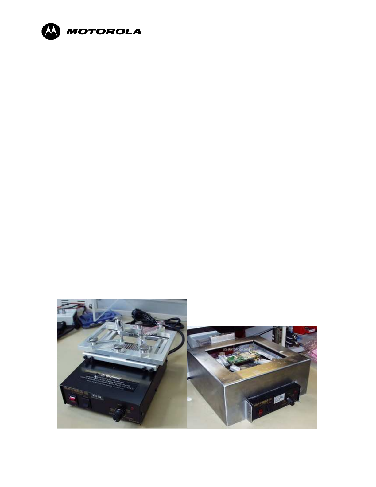
- Advice on working with lead free soldering/underfilm
- Use lead free flux
- Use preheater(HAKKO 853)
- Use tool for resolder (PA and U250), part no 19500950 (Pre soldering Fixture)
-
part no 99991966 (Metal stencil GSM Edge)
part no 19501966 (Mounting Bracket GSM
Edge)
part no 99991964 (Metal stencil for PA)
part no 19501964 (Mounting bracket for PA)
Use of preheater
Motorola GmbH, CSS Center, Mobile Devices
Doc. No: TSG_V3i/V3_05
Date: 04.09.2006
Title: Troubleshooting-Guide V3i / V3_05 Page: 4 / 22
Repair Support Information
© Copyright 2003-2006 Motorola Inc. All Rights reserved.
Motorola internal use
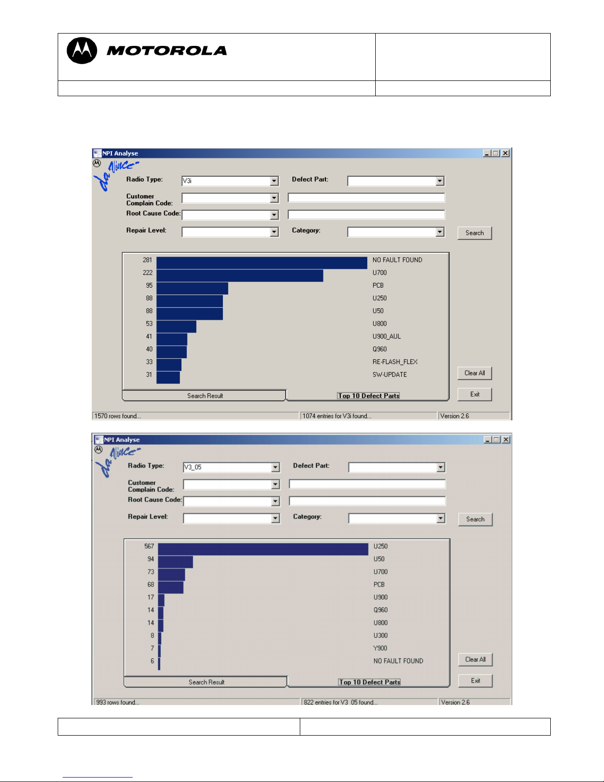
Top Ten defect parts
The following is an analysis summery of the V3i and V3_05 repaired during NPI process by
the Repair Entitlement Group CSS Flensburg
Motorola GmbH, CSS Center, Mobile Devices
Doc. No: TSG_V3i/V3_05
Date: 04.09.2006
Title: Troubleshooting-Guide V3i / V3_05 Page: 5 / 22
Repair Support Information
© Copyright 2003-2006 Motorola Inc. All Rights reserved.
Motorola internal use
Troubleshooting Guide
First Step
Please make sure beforehand, that the problem at hand is not a SW related issue that can be
solved with a 1FF update and a Master Reset/Clear. In many cases a simple Master Reset can
already fix the problem.
The following section is meant to be a help in troubleshooting problems which are already
Identified as PCB related
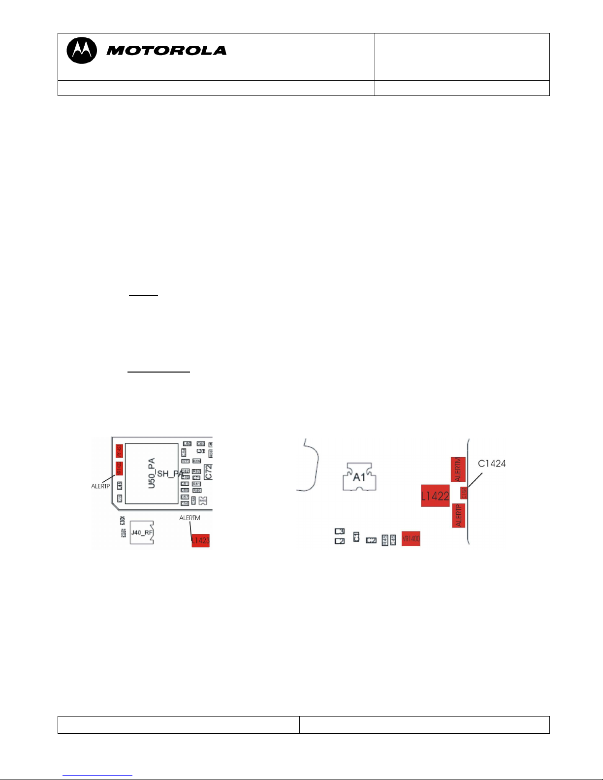
ALT01 Alert – Ring tone, no
ALT02 Alert – Ring tone, low
ALT03 Alert – Ring tone, noise/distortion
Check ALERTP and ALERTM -- both should have around 2.1Vdc
- If not
check L1422/L1423/ for broken connection,C1424 for low resistance
VR1400/VR1422/VR1423 for shortcut to ground
- check PCB for open tracks from ALERTM to U900-V10 /ALERTP to U900-U8
- you can either use“Repair-Studio” to switch on 1 kHz tone to the alert to check for
open tracks, but be careful: You can have 1 kHz and audio in call at
ALERTM/ALERTP, but no alert-tone, because the ATLAS is defect!
if 1kHz is ok, replace Atlas (U900). Please use underfilm for U900.
The alert signal is converted to analog and amplified by the ATLAS, but generated by the
Neptune, so if the ATLAS alert audio path is ok there could be a problem with the
Neptune not generating the alert signal.
ALT11 Alert – Vibrator, no
ALT12 Alert – Vibrator, weak
Turn on vibrator using Repair Studio/ Radiocomm. Measure V_VIB – should be about
2Vdc.V_VIB is provided directly by the ATLAS (U900).To verify if the vibrator is defective
a simple method is to provide a supply voltage (1Vdc should be enough) via test probes
directly on the vibrator G1 (radio in off state!).It should be rotating, if not replace the vibrator
G1.Check the diode D_VIB . Otherwise replace ATLAS (U900). Please use underfilm for
U900.
Motorola GmbH, CSS Center, Mobile Devices
Doc. No: TSG_V3i/V3_05
Date: 04.09.2006
Title: Troubleshooting-Guide V3i / V3_05 Page: 6 / 22
Repair Support Information
© Copyright 2003-2006 Motorola Inc. All Rights reserved.
Motorola internal use
Vibrator G1
D_VIB
V_VIB
ac tive:2 V
from ATLAS
GND
AUDxx Audio problems
First step on every audio related problem is to identify which audio paths are affected. If the
audio signals in a loop are ok, there could be an audio problem in a network call. This could
be due to an ATLAS or Neptune related defect.
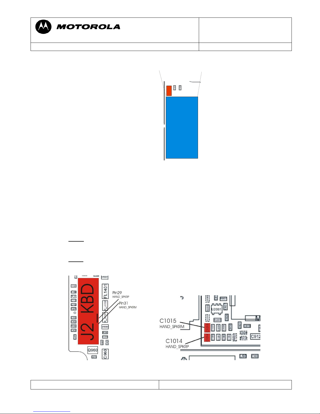
AUD01 Audio – Earpiece, no
AUD02 Audio – Earpiece, low
Check HAND_SPKRM at C1014 and HAND_SPKRP at C1015. Both should have around
1.4Vdc offset voltage, if audio-loop is switched on and additional up to 2,7Vpp at 1 kHz, if
test-tone is switched on.
- If not check J2 for solder shorts,C1014/1015 for low resistance
- (eventually) check PCB on open tracks from J2 to C1014/U900-T6 and J2 to
C1015/U900-R7
- If ok, replace Atlas (U900). Please use underfilm for U900.
Motorola GmbH, CSS Center, Mobile Devices
Doc. No: TSG_V3i/V3_05
Date: 04.09.2006
Title: Troubleshooting-Guide V3i / V3_05 Page: 7 / 22
Repair Support Information
© Copyright 2003-2006 Motorola Inc. All Rights reserved.
Motorola internal use
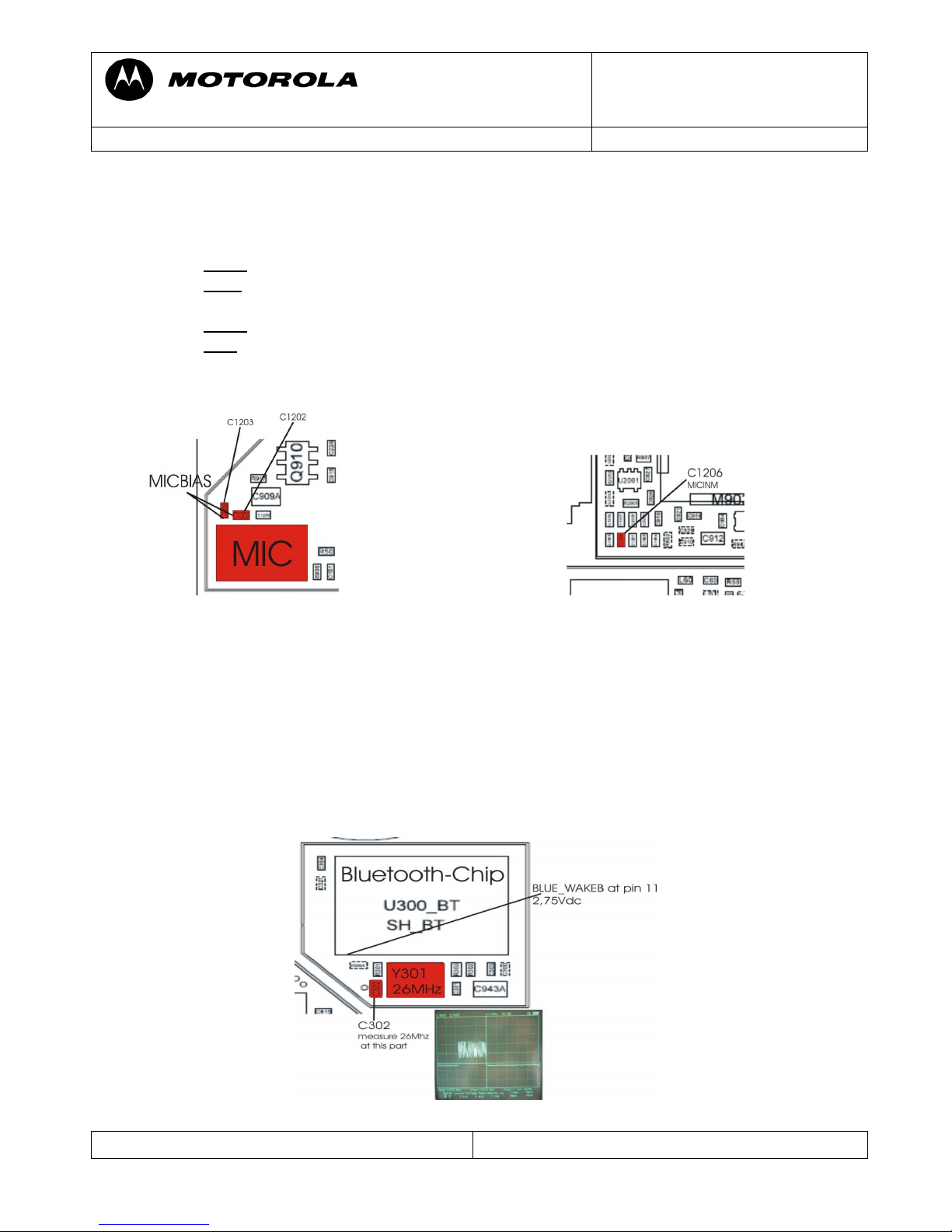
AUD07 Audio – MIC, No
AUD08 Audio – MIC, Low
Set radio in audio loop using Repair Studio/Radiocomm
- check MIC BIAS1 at C1207 – should be around 1,75Vdc
- if not
check C1207/1206/1201/1202/1200/1203 for low resistance
- if ok check MIC_IN_M at C1206 while blowing into the microphone to see the
audio signal caused by the blowing
- if not replace microphone
- if ok replace ATLAS (U900) Please use underfilm for U900.
ACC07 -- Accessory - Bluetooth module, no Operation
Verify it Bluetooth can be activated and is able to find other Bluetooth devices.
- If not, check oscillator Y301 (26MHz).
- check the BLUE_WAKEB
- replace U300
- If not, replace Neptune (U800)
Note: You can only measure the signals, when Bluetooth is activated.
pulsed signal
 Loading...