

Motorola V150 Service Manual

V150
Level III
Circuit Description V1.0

V150 – Level III Circuit Description
2
General
The V150 contains the Triton Chipset (LCA) consist of:
ALGAE, NEPTUNE, ATHENA, SEAWEED and DIAMONDHEAD with extrenal protection
circuit. The phone is designed with same haousing like V50, with an external Antenna and as
Quard Band Tranceiver but will only be sold as Dual Band 850/1900 MHz or 900/ 1800 Mhz.
This is done by flexing the phone to the need of the different regions.
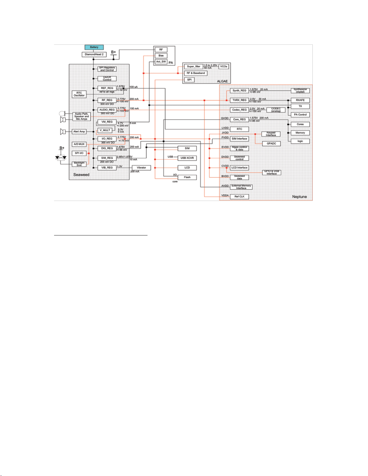
Power Distribution Overview
Power is distributed throughout the Triton Chipset from a variety of linear regulators, a capacitive
voltage multiplier, as well as direct connections to B+. The primary power manager is the
Seaweed IC, which receives its voltage input from the battery via the Diamond Head2 B+ output.
A detailed description of DiamondHeads charge/safety functionality is presented from Page 7-9.
Seaweed alone contains 8 of the 12 linear regulators present in the chipset. These regulators
provide power to module blocks both internal and external to Seaweed. In addition, Seaweed
contains a capacitive voltage multiplier that provides a 5.3V nominal output, which is linearly
regulated down to 4.7V to supply the higher voltage modules. Seaweed’s 1.575V trimmed
voltage reference is used as the reference to all Seaweed regulators as well as
all Neptune regulators. Neptune contains 4 linear regulators that are powered from the Seaweed
regulated supplies. Both the Core and Synthesizer Regulators are used to provide a more solid
supply to their respective blocks. The TX/RX and Codec Regulators are used to improve power
supply rejection on their blocks, which are sensitive to noise and supply ripple. The rest of the
Neptune blocks are powered directly from the Seaweed regulated supplies.
Algae contains 1 linear regulator which is powered from a Seaweed regulated supply. This Super
Filter Regulator provides power to the noise sensitive VCO’s. The rest of the Algae blocks are
powered directly from the Seaweed regulated supplies.
The Athena PA module receives its RF power directly from radio B+, due to its voltage and
current requirements. The rest of the Athena blocks are powered directly from the Seaweed
regulated supplies.
The Figure next page shows the intended power distribution of the Triton Chipset, based on
voltage and current requirements, as well as considerations for noise and isolation. All regulator
outputs are shown with their nominal voltage, output tolerance, and current sourcing capability.
See drawing 1.0 below
GSM Service Support
Motorola Proprietary Information
V150 – Level III Circuit Description
3
Drawing 1.0
Power Up/ Down Sequence
Radio Power On Methodes:
The phone is enabled by one of the following conditions:
1. A high to low transition on the Seaweed PWR_SW input Pin F2 when the B+ voltage is
above the Under Voltage Threshold of 2.65V DC (nominal). PWR_SW is asserted low
by the ON/OFF key depression.
2. A low to high transition on the Seaweed EXT_PWR_ON input.
EXT_PWR_ON is asserted by the DiamondHead 2 IC when external power from a
charger is applied and when the battery voltage is above the Turn On Threshold of 3.0V
(nominal).
3. A low to high transition on the Seaweed STANDBY_TODAI input when the B+
voltage is above the Under Voltage Threshold of 2.65Vdc (nominal) and RESETB is set
low.
STANDBY_TODAI is asserted by the Neptune IC when the phone recovers from a
power cut or when a Time of Day alarm from the Real Time Clock is due.
4. The B+ voltage rises above the Under Voltage Threshold of 2.65V nominal.
GSM Service Support
Motorola Proprietary Information

V150 – Level III Circuit Description
4
Radio Power Down Methods:
The phone is disabled by one of the following conditions:
5. Software-initiated power down.
When the user requests to turn the phone off by pressing the ON/OFF key, or when a low
battery voltage is detected by software through the general purpose ADC measurement,
or when the RTC timer expires, Neptune drives the WDI line low. When WDI goes low
the Seaweed IC and therefore the phone turns off.
6. Hardware-initiated power down.
When the B+ voltage drops below the UV Comparator Threshold, RESETB goes low
which in turn causes Neptune to put the WDOGB output into a high impedance state. An
internal pull down resistor on Seaweed brings the WDOGB line low and thus the phone
shuts off.
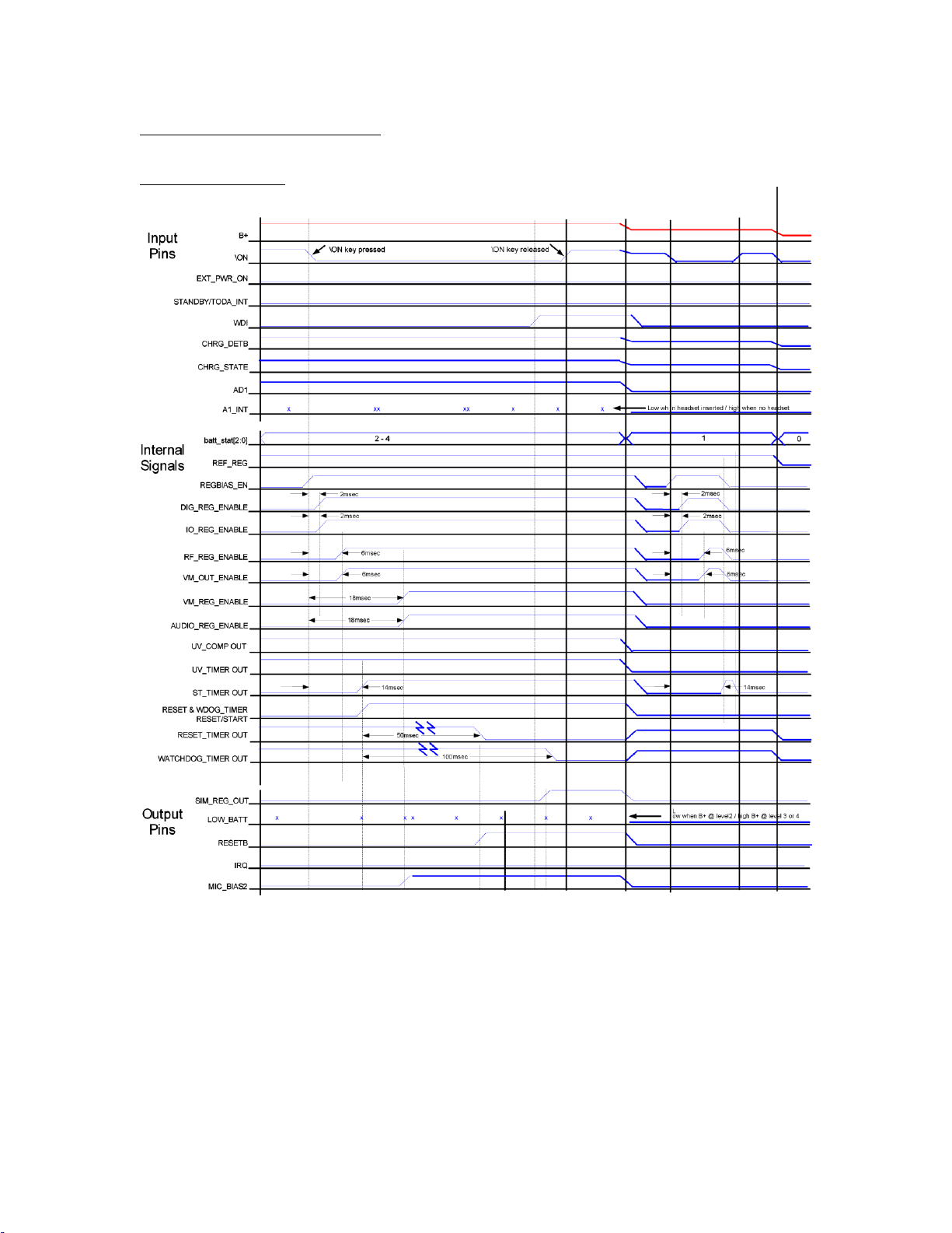
Power Up/ Down Sequence
Power On from ON/OFF Key:
1. ON/OFF key is pressed when the B+ volt. is above the U. Volt. threshold (B+>2.55V)
2. PWR_SW goes low internal \ON goes high
3. ReferenceRegulator RTC_GRP is always on if battery is in a good range
4. In U900 the internal signal REGBIAS_EN goes high
5. 2 msec later the two Regulators DIG_1,875 and IO_2,65 goes high
6. 4msec later the two Regulators RF_REG and VM_REG goes high
7. 8msec later the internal Seaweed WATCHDOG and RESET Timer start counting
8. 4msec later the two RegulatorsVM_REG and AUDIO_REG goes high
9. 46msec later RESET Timer output goes low, RESETB goes high
10. within 50msec Neptune asserts WDOGB before Watchdog timer output goes low
11. ON/OFF key is released
Power OFF from ON/OFF Key:
1. ON/OFF key is pressed
2. PWR_SW goes low
3. In U900 the internal signal REGBIAS_EN goes high
4. 2 msec later the two Regulators DIG_1,875 and IO_2,65 goes low
5. 4msec later the two Regulators RF_REG and VM_REG goes low
8msec later REGBIAS_EN goes low; all regulators except for REF_REG are disabled
GSM Service Support
Motorola Proprietary Information

V150 – Level III Circuit Description
5
Power OFF from Under Voltage:
1. B+ voltage drops below UV Threshold (B+<2.55V)
2. Internal Seaweed UnderVoltage Comparator and UV Timer output goes low,
3. RESETB goes low
4. within 5msec Neptune puts the WDOGB output into a high impedance state and 100K
pulldown on Seaweed pulls WDI low
5. Int. U920 signal REGBIAS_EN goes low; all Reg. except for REF_REG are disabled
Power Sources:
Power for the unit can be obtained from 2 sources, battery pack or external power.
Battery Pack:
The battery connector P800 will have 3 contacts, these being:
Pin 1 – GROUND
Pin 3 – ATH_B+ as source on the Diamond IC U920.
Pin 2 – TP_BATT_DETB as battery temperature control signal to U920 Pin 19.
External Charger:
The external Chager source is EXT_B+ connected via Charger Jack J900.
There are two signals to read and control the external Source.
The Signal CHRG_ SW is used to control the output current of EXT source, If high
CHRG_TYP line will be read (External Charger pull down resistor biases the voltage on
Charger Jack Pin2) and current is set to 400mA limit. If low current is set to 900mA limit.
External Charger could be:
1. an unregulated, current-limited wall adapter
2. a 6.2VDC nominal Vehicle Power Adapter with 1A nominal current limit
GSM Service Support
Motorola Proprietary Information
V150 – Level III Circuit Description
6
Power Up/ Down Sequence
Timing Diagram:
Drawing 1.1
GSM Service Support
Motorola Proprietary Information
 Loading...