

Page 1

MTR2000
™
Base Station, Repeater and Receiver
For Analog Conventional,
and T runking Systems
Installation and Operation
Manual
68P81096E20-N
Page 2

COMPUTER SOFTWARE COPYRIGHTS
The Motorola products described in this instructions manual may include copyrighted Motorola computer programs stored in semiconductor
memories or other media. Laws in the United States and other countries preserve for Motorola certain exclusive rights for copyrighted computer programs. Including the exclusive right to copy or reproduce in any form the copyrighted computer program. Accordingly, any copyrighted Motorola computer programs contained in the Motorola products described in this Instruction manual may not be copied or reproduced in
any manner without the express written permission of Motorola. Furthermore, the purchase of Motorola products shall not be deemed to grant
either directly or by implication, estoppel or otherwise, any license under the copyrights, patents or patent applications of Motorola, except for
the normal nonexclusive, royalty free license to use that arises by operation of law in the sale of a product.
COMMERCIAL WARRANTY (U.S. Only)
Motorola radio commun ic ati ons p roduc ts are wa r ranti ed t o be fr ee fr om defe cts in m ateri al and wor k man ship for
a period of ONE (1) YEAR, (except for crystals and channel elements which are warrantied for a period of ten (10)
years from the date o f shipmen t. Parts, includ ing cry stals and cha nnel elem ents, will be repl aced and l abor will
be provided free of charge for the full warranty period, from the date of shipment. Thereafter purchaser must pay
for the labor involved in repairing the product and replacing the parts at the prevailing rates together with any transportation charges to or from the place where warranty service is provided. This express warranty is extended by
Motorola Communications and Electronics Inc., 1301 E. Algonquin Road, Schaumburg, Illinois 60196, to the original purchaser only, and only to those purchasing for purpose of leasing or solely for commercial, industrial, or government use.
THIS WARRANTY IS GIVEN IN LIEU OF ALL OTHER WARRANTIES EXPRESSED OR IMPLIED WHICH ARE
SPECIFICALL Y EXCLUDED, INCLUDING WARRANTIES OF MERCHANT ABILITY OR FITNESS FOR A PARTICULAR PURPOSE. IN NO EVENT SHALL MOTOROLA BE LIABLE FOR INCIDENTAL OR CONSEQUENTIAL DAMAGES TO THE FULL EXTENT SUCH MAY BE DISCLAIMED BY LAW.
In the event of a defect, malfunction or failure to conform to specifications established be seller, or if appropriate,
to specifications accepted by Seller in writing, during the period shown, Motorola, at its option, will either repair or
replace the product or refund the purchase price thereof, and such action on the part of Motorola shall be the full
extent of Motorola’s liability hereunder.
This warranty is void if:
a. the product is used in other than its normal and customary manner;
b. the product has been subject to misuse, accident, neglect or damage;
c. unauthorized alterations or repairs have been made, or unapproved parts used in the equipment.
This warranty extends only to individual products, batteries are excluded. Because each radio system is unique,
Motorola disclaims liability for range, coverage, or operation of the system as a whole under this warranty except
by a separate written agreement signed by an officer of Motorola.
LICENSED PROGRAMS -- Motorola software provided in connection with this order is warrantied to be free from
reproducible defects for a period of one (1) year. All material and labor to repair any such defects will be provided
free of charge for the full warranty period, and SUBJECT TO THE DISCLAIMER IN BOLD FACE TYPE.
Non-Motorola manufactur ed products are excluded from thi s warranty, but subject to the warra nty provided by
their manufacturers, a copy of which will be suppled to you on specific written request.
In order to obtain performance of thi s warranty, purchaser must contact its Motorola salesper son or Motorola at
the address shown in the second paragraph, attention Quality Assurance Department.
FCC INTERFERENCE WARNING
The FCC requires that manuals pertaining to Class A and Class B computing devices must contain warnings
about possible interference with local residential radio and TV reception. This warning reads as follows:
NOTE: The equipment has been tested and found to comply with the limits for a Class B digital device, pursuant
to Part 15 of the FCC Rules. These limits are designed to provide reasonable protection against harmful interference when the equipment is operated in a commercial or residential environment. This equipment generates, uses, and can radiate radio frequency energy and, if not installed and used in accordance with its
instruction manual, may cause harmful interference to radio communication.
ELECTROMAGNETIC COMPATIBILITY
This product conforms with the protection requirements of Council Directive 89/336/EEC
of 3rd May 1989 (EM C) on the approx imati on of t he laws o f the Membe r States relating
to electromagnetic compatibility.
Page 3

Material Content
ENVIRONMENTAL INFORMATION
The material content of the MTR2000 is 16% of the product it replaces.
The following table provides a rough estimate of the material content of
the station. The actual percentages vary in relation to the station configuration. The power supply is not included in the percentage of weights
since the end-of -life value is dependent on the model of supply used in
the station.
Most of the Material categories are self explanatory. Co pper bearing materials:
• include any material that contains copper.
• primarily consist of circuit boards.
• exclude cables (separate Material category).
Material % by weight
Features
Aluminum 92%
Steel 2%
Copper Bearing 4%
Cable 1%
Polycarbonate 1%
Beryllium Oxide has been used in the power amplifier. Beryllium Oxide
should not be subjected to any process which will generate dust.
Over 92% of the station is made of aluminum, one of the most recycled
materials commonly available today . In addition, the aluminum used in
the station consists of 90-95% recycled content.
Plastic use has been minimized since the market for recycled engineering plastics is limited. The plastic which has been used for the front panel is a relatively clean and pure resin.
06/28/05 68P81096E20-N i
Page 4

Disposal of your Electronic and Electric Equipment
Please do not dispose of Electronic and Electric Equipment or Electr onic and Electric
Accessor ies wi th your house hold wa ste. In some c ountr ies or re gions , col lect ion sys tems have been set up to handle waste of electrical and electronic equipment.
In European Union countries, please contact your local equipment supplier representative or service center for information about the waste collection system in your
country.
Disposal Guideline
The following symbol on a Motorola product indicates that the product should not
be disposed of with household waste.
ii 68P81096E20-N 06/28/05
Page 5

Scope of Manual
Note
CAUTION
!
STOP
WARNING
STOP
IMPORTANT
Documentation Conventions
FOREWORD
This manual is intended for use by experienced technicians familiar with
similar types of equipment.
It provides information which allows installation personnel to unpack,
mechanically install, el ectrically con nect, and verify operation of the station.
The information in this manual is current as of the printing date. Changes which occur after the printing date are incorporated by Manual Revisions (SMR). These SMRs are added to the manuals as the engineering
changes are incorporated into the equipment.
Documentation conventions are used in this manual to highlight certain
information.
The area to the left of the text column contains key words and graphic
symbols which allow the reader to quickly identify desired information.
The following text highlight sym b ols are used:
A note symbol indicates important inf ormation that helps improve the
described function.
A caution symbol indicates a potential problem, unle ss the prope r actions are taken. A caution also explains how to avoid the problem.
A WARNING symbol indicate s the pote ntial for personal injur y or serious system degradation unless the proper actions are taken. A
WARNING also explains how to avoid the problem.
An IMPOR TANT symbol indi cates the potenti al for damaging the station unless the proper actions are taken. An IMPORTANT note also
explains how to avoid the problem.
06/28/05 68P81096E20-N ix
Page 6

GENERAL SAFETY INFORMATION
The United States Department of Labor, through the provisions of the Occupational Safety and Health Act of 1970
(OSHA), has established an electromagnetic energy safety standard which applies to the use of this equipment.
Proper use of this radio will result in exposure below the OSHA limit. The following precautions are recommended:
• DO NOT operate the transmitter of a mobile radio when someone outside the vehicle is within two feet
(0.6 meter) of the antenna.
• DO NOT operate the transmitter of a fixed radio (base station, microwave and rural telephone rf equipment) or marine radio when someone is within two feet (0.6 meter) of the antenna.
• DO NOT operate the transmitter of any radio unless all rf connectors are secure and any open connectors
are properly terminated.
In addition:
• DO NOT operate this equipment near electrical blasting caps or in an explosive atmosphere.
• All equipment must be properly grounded according to Motorola installation instructions for safe operation.
• All equipment should be serviced only by a qualif ied technician.
• An operating license may be required to operate this station.
Refer to the appropriate section of the product service manual for additional pertinent safety information.
Some station components can become extremely hot during station operation. Turn off a ll power to the s tation, and wait until sufficiently coo l
before touching the station.
x 68P81096E 20-N 06/28/05
Page 7

DESCRIPTION
MTR2000
Station, Repeater and Receiver
For Analog Conventional,
and T runking Systems
Table of Contents
Scope of Manual. . . . . . . . . . . . . . . . . . . . . . . . . . . . . . . . . . . . . . . . . . . . . . . . . . . . . . . . . . . . . . . . . . .ix
Documentation Conventions . . . . . . . . . . . . . . . . . . . . . . . . . . . . . . . . . . . . . . . . . . . . . . . . . . . . . . . . ix
General Safety Information. . . . . . . . . . . . . . . . . . . . . . . . . . . . . . . . . . . . . . . . . . . . . . . . . . . . . . . . . .x
™
DESCRIPTION 68P81096E36
INTRODUCTION . . . . . . . . . . . . . . . . . . . . . . . . . . . . . . . . . . . . . . . . . . . . . . . . . . . . . . . . . . . . . . . . . . . . . . . .1
Flexible Mechanical Design . . . . . . . . . . . . . . . . . . . . . . . . . . . . . . . . . . . . . . . . . . . . . . . . . . . . . . . . .1
Electrical Design . . . . . . . . . . . . . . . . . . . . . . . . . . . . . . . . . . . . . . . . . . . . . . . . . . . . . . . . . . . . . . . . . . 2
Trunking Capability . . . . . . . . . . . . . . . . . . . . . . . . . . . . . . . . . . . . . . . . . . . . . . . . . . . . . . . . . . . . . . . 2
Summary of Operating Features . . . . . . . . . . . . . . . . . . . . . . . . . . . . . . . . . . . . . . . . . . . . . . . . . . . . . 3
, MOTOROLA, MTR2000, Spectra-T AC, DigiTAC and Private Line are trademarks of Motorola Inc.
TORX is a trademark of Camcar Division of Textron Inc
Motorola Inc., 2005
All Rights Reserved
Printed in U. S.A.
Government & Enterprise Mobility Solutions
.
1301 E. Algonquin Road, Schaumburg, IL 60196
68P81096E20-N
06/28/05-UP
Page 8

STATION COMPONENTS . . . . . . . . . . . . . . . . . . . . . . . . . . . . . . . . . . . . . . . . . . . . . . . . . . . . . . . . . . . . . . . . 4
INSTALLATION
FUNCTIONAL THEORY OF OPERATION . . . . . . . . . . . . . . . . . . . . . . . . . . . . . . . . . . . . . . . . . . . . . . . . . . 5
Transmitter Circuitry Operation . . . . . . . . . . . . . . . . . . . . . . . . . . . . . . . . . . . . . . . . . . . . . . . . . . . . 5
Receiver Circuitry Operation . . . . . . . . . . . . . . . . . . . . . . . . . . . . . . . . . . . . . . . . . . . . . . . . . . . . . . . 7
Station Control Module Operation . . . . . . . . . . . . . . . . . . . . . . . . . . . . . . . . . . . . . . . . . . . . . . . . . . 8
Wireline Interface Board Operation . . . . . . . . . . . . . . . . . . . . . . . . . . . . . . . . . . . . . . . . . . . . . . . . . 9
Auxiliary I/O Board Operation . . . . . . . . . . . . . . . . . . . . . . . . . . . . . . . . . . . . . . . . . . . . . . . . . . . . . 10
Power Supply Module Operation . . . . . . . . . . . . . . . . . . . . . . . . . . . . . . . . . . . . . . . . . . . . . . . . . . . 11
INSTALLATION 68P81096E37
PRE-INSTALLATION CONSIDERATIONS . . . . . . . . . . . . . . . . . . . . . . . . . . . . . . . . . . . . . . . . . . . . . . . . . 1
Installation Overview . . . . . . . . . . . . . . . . . . . . . . . . . . . . . . . . . . . . . . . . . . . . . . . . . . . . . . . . . . . . . 1
Environmental Conditions at Intended Installation Site . . . . . . . . . . . . . . . . . . . . . . . . . . . . . . . . 2
Equipment Ventilation . . . . . . . . . . . . . . . . . . . . . . . . . . . . . . . . . . . . . . . . . . . . . . . . . . . . . . . . . . . . 3
AC Input Power Requirements . . . . . . . . . . . . . . . . . . . . . . . . . . . . . . . . . . . . . . . . . . . . . . . . . . . . . 4
Equipment Mounting Methods . . . . . . . . . . . . . . . . . . . . . . . . . . . . . . . . . . . . . . . . . . . . . . . . . . . . . 5
Floor-mount Cabinet . . . . . . . . . . . . . . . . . . . . . . . . . . . . . . . . . . . . . . . . . . . . . . . . . . . . . . . 6
Modular Racks . . . . . . . . . . . . . . . . . . . . . . . . . . . . . . . . . . . . . . . . . . . . . . . . . . . . . . . . . . . . 8
Site Grounding and Lightning Protection . . . . . . . . . . . . . . . . . . . . . . . . . . . . . . . . . . . . . . . . . . . . 10
Site Grounding Lightning Protection Recommendations . . . . . . . . . . . . . . . . . . . . . . . . 10
Equipment Grounding Guidelines . . . . . . . . . . . . . . . . . . . . . . . . . . . . . . . . . . . . . . . . . . . 10
Recommended Tools and Equipment . . . . . . . . . . . . . . . . . . . . . . . . . . . . . . . . . . . . . . . . . . . . . . . . 11
Equipment Unpacking and Inspection . . . . . . . . . . . . . . . . . . . . . . . . . . . . . . . . . . . . . . . . . . . . . . . 11
Cabinet Unpacking . . . . . . . . . . . . . . . . . . . . . . . . . . . . . . . . . . . . . . . . . . . . . . . . . . . . . . . . . . . . . . . . 11
iv 68P81096E20-N 06/28/05
Page 9

MECHANICAL INSTALLATION . . . . . . . . . . . . . . . . . . . . . . . . . . . . . . . . . . . . . . . . . . . . . . . . . . . . . . . . . .12
Unpacking Equipment . . . . . . . . . . . . . . . . . . . . . . . . . . . . . . . . . . . . . . . . . . . . . . . . . . . . . . . . . . . . .12
Introduction . . . . . . . . . . . . . . . . . . . . . . . . . . . . . . . . . . . . . . . . . . . . . . . . . . . . . . . . . . . . . . . 12
Unpacking Stations . . . . . . . . . . . . . . . . . . . . . . . . . . . . . . . . . . . . . . . . . . . . . . . . . . . . . . . . . 12
Front Panel – Removal and Replacement . . . . . . . . . . . . . . . . . . . . . . . . . . . . . . . . . . . . . .12
Unpacking Floor-mount Cabinets . . . . . . . . . . . . . . . . . . . . . . . . . . . . . . . . . . . . . . . . . . . .13
Mounting Procedures . . . . . . . . . . . . . . . . . . . . . . . . . . . . . . . . . . . . . . . . . . . . . . . . . . . . . . . . . . . . . . 15
Introduction . . . . . . . . . . . . . . . . . . . . . . . . . . . . . . . . . . . . . . . . . . . . . . . . . . . . . . . . . . . . . . . 15
Installing Racks . . . . . . . . . . . . . . . . . . . . . . . . . . . . . . . . . . . . . . . . . . . . . . . . . . . . . . . . . . . .15
Mounting Floor-mount Cabinets . . . . . . . . . . . . . . . . . . . . . . . . . . . . . . . . . . . . . . . . . . . . .16
Transferring Equipment from Shipping Container to Rack or Cabinet . . . . . . . . . . . . . 16
Installing Slide Rail Assembly in a Motorola Cabinet . . . . . . . . . . . . . . . . . . . . . . . . . . . .17
Installing Slide Rail Assembly in a Non-Motorola Cabinet . . . . . . . . . . . . . . . . . . . . . . . 19
BOARD CONFIGURATION . . . . . . . . . . . . . . . . . . . . . . . . . . . . . . . . . . . . . . . . . . . . . . . . . . . . . . . . . . . . . . . 21
4-Wire Wireline Interface Board . . . . . . . . . . . . . . . . . . . . . . . . . . . . . . . . . . . . . . . . . . . . . . . . . . . . . 21
4-Wire Euro Wireline Interface Board . . . . . . . . . . . . . . . . . . . . . . . . . . . . . . . . . . . . . . . . . . . . . . . . 21
Auxiliary I/O Board . . . . . . . . . . . . . . . . . . . . . . . . . . . . . . . . . . . . . . . . . . . . . . . . . . . . . . . . . . . . . . . 23
ELECTRICAL CONNECTIONS . . . . . . . . . . . . . . . . . . . . . . . . . . . . . . . . . . . . . . . . . . . . . . . . . . . . . . . . . . . . 26
Power Supply Connections . . . . . . . . . . . . . . . . . . . . . . . . . . . . . . . . . . . . . . . . . . . . . . . . . . . . . . . . . 28
AC Input Power Connection . . . . . . . . . . . . . . . . . . . . . . . . . . . . . . . . . . . . . . . . . . . . . . . . . 28
Ground Connection . . . . . . . . . . . . . . . . . . . . . . . . . . . . . . . . . . . . . . . . . . . . . . . . . . . . . . . . 29
DC Input Power Connection . . . . . . . . . . . . . . . . . . . . . . . . . . . . . . . . . . . . . . . . . . . . . . . . . 29
Battery Connection . . . . . . . . . . . . . . . . . . . . . . . . . . . . . . . . . . . . . . . . . . . . . . . . . . . . . . . . . 29
RF Antenna Connections . . . . . . . . . . . . . . . . . . . . . . . . . . . . . . . . . . . . . . . . . . . . . . . . . . . . . . . . . . . 31
System Cable Connections . . . . . . . . . . . . . . . . . . . . . . . . . . . . . . . . . . . . . . . . . . . . . . . . . . . . . . . . . . 32
Telephone Line Connections . . . . . . . . . . . . . . . . . . . . . . . . . . . . . . . . . . . . . . . . . . . . . . . . . . . . . . . .37
Introduction . . . . . . . . . . . . . . . . . . . . . . . . . . . . . . . . . . . . . . . . . . . . . . . . . . . . . . . . . . . . . . . 38
Telephone Line Specifications . . . . . . . . . . . . . . . . . . . . . . . . . . . . . . . . . . . . . . . . . . . . . . . . 39
Location of Telephone Line Connections. . . . . . . . . . . . . . . . . . . . . . . . . . . . . . . . . . . . . . . 40
System Type vs. Wireline Circuit . . . . . . . . . . . . . . . . . . . . . . . . . . . . . . . . . . . . . . . . . . . . . 41
Station Maintenance Connections . . . . . . . . . . . . . . . . . . . . . . . . . . . . . . . . . . . . . . . . . . . . . . . . . . . . 42
POST INSTALLATION CHECKLIST . . . . . . . . . . . . . . . . . . . . . . . . . . . . . . . . . . . . . . . . . . . . . . . . . . . . . . . . 43
Applying Power . . . . . . . . . . . . . . . . . . . . . . . . . . . . . . . . . . . . . . . . . . . . . . . . . . . . . . . . . . . . . . . . . . 43
Verifying Proper Operation . . . . . . . . . . . . . . . . . . . . . . . . . . . . . . . . . . . . . . . . . . . . . . . . . . . . . . . . .44
Front Panel LEDs . . . . . . . . . . . . . . . . . . . . . . . . . . . . . . . . . . . . . . . . . . . . . . . . . . . . . . . . . . 44
Listening For Audible Alarms . . . . . . . . . . . . . . . . . . . . . . . . . . . . . . . . . . . . . . . . . . . . . . . 46
Exercising Radio Operation . . . . . . . . . . . . . . . . . . . . . . . . . . . . . . . . . . . . . . . . . . . . . . . . . . 46
06/28/05 68P81096E20-N v
Page 10

OPTIMIZATION . . . . . . . . . . . . . . . . . . . . . . . . . . . . . . . . . . . . . . . . . . . . . . . . . . . . . . . . . . . . . . . . . . . . . . . . . 47
STATION OPERATION
Optimizing Tasks . . . . . . . . . . . . . . . . . . . . . . . . . . . . . . . . . . . . . . . . . . . . . . . . . . . . . . . . . . . . . . . . . 47
Copying Station Codeplug Date To a PC-compatible Computer . . . . . . . . . . . . . . . . . . . . . . . . . 47
INSTALLING STATION HARDWARE OPTIONS . . . . . . . . . . . . . . . . . . . . . . . . . . . . . . . . . . . . . . . . . . . . 48
STATION OPERATION 68P81096E38
DESCRIPTION . . . . . . . . . . . . . . . . . . . . . . . . . . . . . . . . . . . . . . . . . . . . . . . . . . . . . . . . . . . . . . . . . . . . . . . . . . 1
LED Indicators . . . . . . . . . . . . . . . . . . . . . . . . . . . . . . . . . . . . . . . . . . . . . . . . . . . . . . . . . . . . . . . . . . . 2
External Device Connections . . . . . . . . . . . . . . . . . . . . . . . . . . . . . . . . . . . . . . . . . . . . . . . . . . . . . . . 3
Service Connections . . . . . . . . . . . . . . . . . . . . . . . . . . . . . . . . . . . . . . . . . . . . . . . . . . . . . . . . . . . . . . . 4
vi 68P81096E20-N 06/28/05
Page 11

List of Figures
DESCRIPTION
INSTALLATION
STATION OPERATION
DESCRIPTION 68P81096E36
Figure 1. MTR2000 Station . . . . . . . . . . . . . . . . . . . . . . . . . . . . . . . . . . . . . . . . . . . . . . . . . . .1
Figure 2. MTR2000 Station Components . . . . . . . . . . . . . . . . . . . . . . . . . . . . . . . . . . . . . . .4
Figure 3. MTR2000 Station Functional Block Diagram (Sheet 1 of 2) . . . . . . . . . . . . . . 14
Figure 3. MTR2000 Station Functional Block Diagram (Sheet 2 of 2) . . . . . . . . . . . . . . 15
INSTALLATION 68P81096E37
Figure 1. Floor-mount Cabinet – Dimensions and Clearances . . . . . . . . . . . . . . . . . . . . .7
Figure 2. Modular Rack – Dimensions and Clearances . . . . . . . . . . . . . . . . . . . . . . . . . . . 9
Figure 4. Unpacking Procedures - Floor-mount Cabinets . . . . . . . . . . . . . . . . . . . . . . .14
Figure 5. Slide Rail Installation; Option X968AA (Left Side Shown) . . . . . . . . . . . . . .18
Figure 6. Slide Rail Installation; Option X346AB (Left Side Shown) . . . . . . . . . . . . . . . 20
Figure 7. CLN1203 Wireline Interface Board Jumper Settings . . . . . . . . . . . . . . . . . . . . 21
Figure 8. CLN1204 Wireline Interface Board Jumper Settings . . . . . . . . . . . . . . . . . . . . 22
Figure 9. CLN1206 Auxiliary I/O Board Jumpers . . . . . . . . . . . . . . . . . . . . . . . . . . . . . . 23
Figure 10. Location of External Connectors at Rear of Station . . . . . . . . . . . . . . . . . . . . .27
Figure 11. Making Connections to Storage Battery . . . . . . . . . . . . . . . . . . . . . . . . . . . . . . 30
STATION OPERATION 68P81096E38
Figure 1. Front Panel LEDs. . . . . . . . . . . . . . . . . . . . . . . . . . . . . . . . . . . . . . . . . . . . . . . . . . .2
Figure 2. SCM Connectors . . . . . . . . . . . . . . . . . . . . . . . . . . . . . . . . . . . . . . . . . . . . . . . . . . . 4
06/28/05 68P81096E20-N vii
Page 12

List of Tables
INSTALLATION
INSTALLATION 68P81096E37
Table 1. Configuring Input GPI_14 Function . . . . . . . . . . . . . . . . . . . . . . . . . . . . . . . . 24
Table 2. Configuring Output GPO_14 Function . . . . . . . . . . . . . . . . . . . . . . . . . . . . . . 24
Table 3. Configuring Output GPO_15 Function . . . . . . . . . . . . . . . . . . . . . . . . . . . . . . 25
Table 4. System Connector – Commonly Used Pins . . . . . . . . . . . . . . . . . . . . . . . . . . 33
Table 5. Summary of Auxiliary Inputs/Outputs at the System Connector . . . . . . . . 34
Table 6. J5 SYSTEM CONNECTOR, Row A Pins . . . . . . . . . . . . . . . . . . . . . . . . . . . . . 35
Table 7. J5 SYSTEM CONNECTOR, Row B Pins . . . . . . . . . . . . . . . . . . . . . . . . . . . . . 36
Table 8. J5 SYSTEM CONNECTOR, Row C Pins . . . . . . . . . . . . . . . . . . . . . . . . . . . . . 37
Table 9. Type 5 and “3002” Phone Line Specifications . . . . . . . . . . . . . . . . . . . . . . . . . 39
Table 10. Wireline Connector Line Pair Assignments . . . . . . . . . . . . . . . . . . . . . . . . . . 40
Table 11. System Types vs. Wireline Circuit Matrix . . . . . . . . . . . . . . . . . . . . . . . . . . . . 41
Table 12. Station Maintenance Connections on the SCM . . . . . . . . . . . . . . . . . . . . . . . . 42
viii 68P81096E20-N 06/28/05
Page 13

1 INTRODUCTION
Note
Figure 1. MTR2000 Station
DESCRIPTION
The Motorola MTR2000 Base Station/Repeater provides analog con v entional and trunking capabilities in a reliable, software-controlled design. An innovative modular design and microprocessor-controlled Station Control
Module (SCM) allows for superior station flexibility and simplified system upgrades.
All of the features described in this manual may not be currently supported
to the “Summary of Operatin g Features” section for a list of standard feat ures, optional features, and planned future features.
Flexible Mechanical Design
All elements of the station are designed for EIA 48.3cm (19") rack mounting, allowing the equipment to be mounted in standard telephone-style equipment racks, or
various sizes of Motorola cabinets. Figure 1 sho ws a typical 40W station.
. Refer
Motorola Inc., 2005
All Rights Reserved
Printed in U.S.A.
Government & Enterprise Mobility Solutions
1301 E. Algonquin Road, Schaumburg, IL 60196
68P81096E36-H
06/28/05-UP
Page 14

Description
Electrical Design
Transmitter Circuitry
The station transmitter circuitry is designed for continuous duty operation and may
be operated at full rated power. Output power is continually monitored by an internal directional coupler. The forward power voltage from the coupler feeds a power
control loop which continually adjusts and maintains the desired output power. All
adjustments are electronic, including deviation and output power.
Receiver Circuitry
The station receiver circuitry features multiple bandwidth (12.5kHz, 20kHz, 25kHz,
and 30kHz) capability. Injection signals for the first and second mixers are generated
by frequency synthesizer circuitry electronically controlled by the Station Control
Module. All receive signals (analog) are detected and digitized before being sent to
the Station Control Module, providing improved, consistent audio quality throughout the coverage area.
Trunking Capability
Station Control Module
The Station Control Module is microprocessor-based and features extensive use of
ASIC and digital signal processing technology. The module serves as the main controller for the station, providing signal processing and operational control for the station modules.
Wireline Circuitry
The station wireline circuitry options provide a wide variety of telephone interfaces
and control mechanisms such as Tone Control. Telephone line connections are easily
made to the wireline circuitry via connectors on the rear of the station.
When equipped for trunking capability, the station can operate in Motorola's Smartnet™ or the most advanced wide-area trunking system – SmartZone. The station can
operate as a remote voice channel or control channel repeater. The station interfaces
to a T runking Central Controller (TCC) which provides the call processing and channel assignment tasks.
2 68P81096E36-H
06/28/05
Page 15

Summary of Operating Features
Standard Features
The following are a few of the standard features:
• FRU maintenance philosophy (reducing down time).
• Easily programmed via Radio Service Software (RSS ).
• Extensive Self-Test Diagnostics and Alarm Reporting through RSS.
• Expansion and upgrades performed by module replaceme n t.
• Highly reliable and accurate continuous duty transmitter circuitry.
• Compatible (with appropriate options) with conventional analog signaling.
• Wide operating temperature range: -30°C to +60°C (-22°F to +140°F).
• Battery Backup Connector – allows connection to battery backup system which
automatically reverts to battery backup operation in the event of ac power failure.
•RA/RT
• Wide voltage supply range (AC or DC), with no setup configuration.
Description
Optional Features
The following are some of the leading optional features for the station:
• Double Circulator Option – provides additional isolation and intermodulation
protection for rf-congested transmitter sites (not available on 350MHz stations).
• Microprocessor Radio Telephone Interconnect (MRTI) – allows connection of
conventional station to the telepho ne network.
• Trunking – allows trunking repeater to operate as part of a Smartnet or Smart-
Zone system; through Auxiliary I/O board (CLN1206).
• Wildcard Input/Output; through Auxili ary I/O board (CLN1206).
• Main Standby; through Auxiliary I/O board (CLN1206).
• Multi-coded Squelch Interface; through Zetron Model 38 Repeater Panel.
• Console Priority Interface; through 8-Wire Wireline Interface Board (CLN1205).
• Auxiliary Input/Output for conventional operation; through Auxiliary I/ O
board (CLN1206).
Features Not Offered
Please disregard any references to the following items since they are not available
for the MTR2000:
• DC Remote control for the 4-wire Wireline Interface Board, CLN1203.
• Second Receiver configuration of the MTR2000.
68P81096E36-H 3
06/28/05
Page 16

Description
2 STATION COMPONENTS
Figure 2. MTR2000 Station Components
Power Supply
Module
Bottom Plate
Exciter Module
Receiver
Module
Sta tion Control M odule
Power Amplifier
Module
Front Cover
NOTE: Fans and fan covers
are only used on high power
Power Amplifier modules and
Power Supplies.
Backplane
NOTE: Fans and fan covers
are only used on high power
Power Amplifier modules and
Power Supplies.
Fan Cover
Auxiliary I/O
Board
Top Plate
Fan
Wireline
Interface Board
Figure 2 shows the modules and components that comprise a station.
4 68P81096E36-H
06/28/05
Page 17

Description
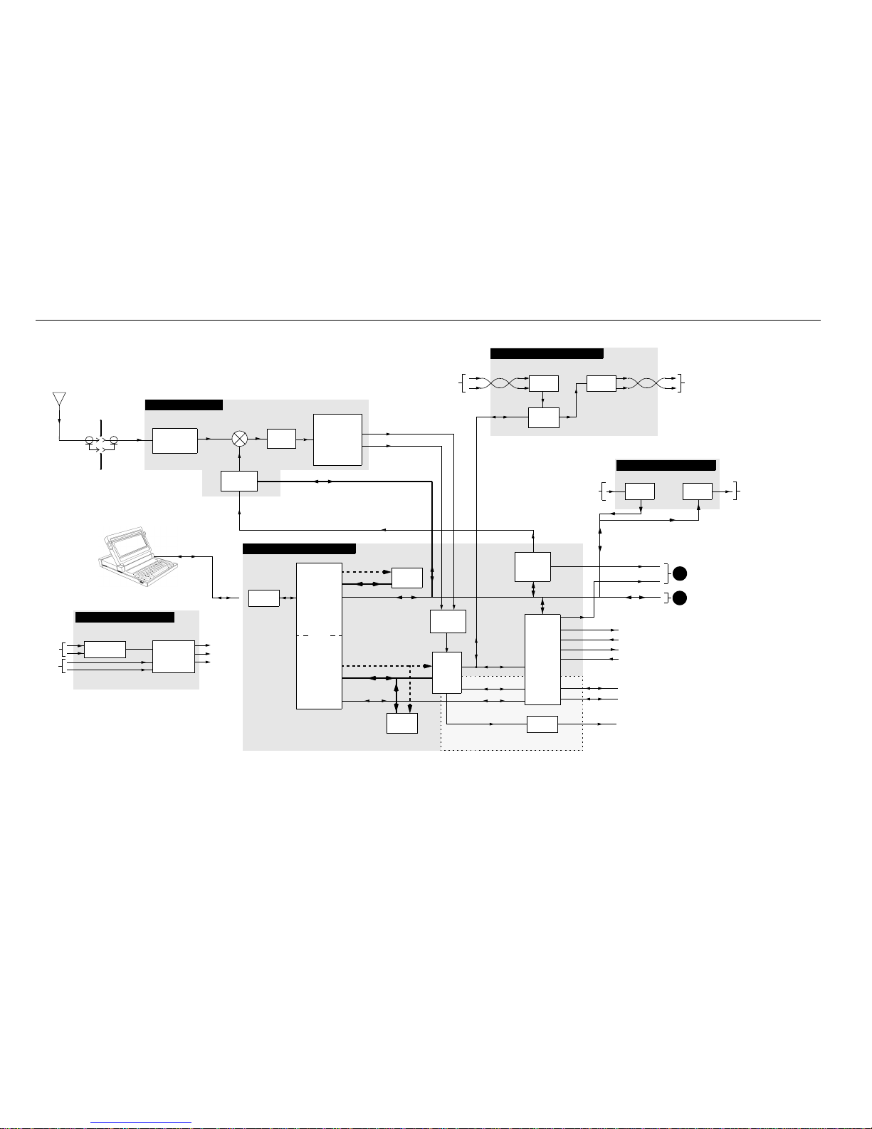
3 FUNCTIONAL THEORY OF OPERATION
The following functional theory of operation provides an overview of the station circuitry. For a more thorough
functional desc ription of a particular module , refer to the STATIO N MODULES section of the appropriate bandspecific Instruction Manual. The block diagram in Figure 3 supports the following functional theory of operation.
Transmitter Circuitry Operation
Introduction
The T ransmitter Circuitry comprises two modules, the Exciter Module and the Power Amplifier (PA) Module. These modules combine to generate, modulate, and amplify the rf signal which is transmitted via the site transmit antenna. Modulation
sensitivity and power output are adjusted electronically for each channel (through
the Radio Service Software), under the direct control of the Station Control Module
(SCM).
Exciter Module Operation
The Exciter Module, which interfaces directly to the SCM, generates a modulated rf
signal at the desired transmit frequency and sends this signal to the PA for amplification. The circuitry operates as follows.
The transmit synthesizer and VCO (voltage-controlled oscillator) circuitry on the Exciter Module accept frequency programming data from the SCM (via the SPI bus)
and generate an rf carrier at the specified frequency. The VCO is directly modulated
by transmit audio/data from the SCM. The resulting modulated rf signal (at a level
of approximately +12 dBm) is then fed to the PA.
Power Amplifier Module Operation
The PA modules are designed for continuous-duty operation across all bands and
power levels. The actual circuit stages employed in a PA depend on the specific frequency band, power output level and intermodulation requirements. All PA modules contain an Intermediate Power Amplifier (IPA) at the input, a low-pass
filter/directional coupler at the output, and diagnostic and power control circuitry.
High power (100 W) PA m odules employ a single int ernal circulator to protect the PA
from transmitter intermodulation and antenna mismatch (VSWR). The low power
30 W PA module employs two interna l cir cu lato rs. Al l PA stages and ci rc ulat ors ar e
broad-band devices and require no tuning to operate at the station site.
The modulated rf signal from the Exciter Module is input to the IPA in the PA Module, and amplified to within a range of 0 to 10 W (depending on power control signals
from the SCM). In P A Modules operating below 600MHz, the rf signal is fed to either
a Butterfly Module (30W/40W PA models) or a Dual Device Module (DDM – 100W
PA model s). In PA Modules operating above 600 MHz, a 15 W driver is introduced
68P81096E36-H 5
06/28/05
Page 18

Description
between the Pre-driver stage and the Final Module. The gain of the Pre-driver stage
is controlled by a power control voltage which is derived from power control signals
(from the SCM) and high VSWR/thermal protection circuitry on the PA output
board.
A combination of hardware and software controls are used to regulate the power output level. To set the powe r and current limits, the SCM provides software control
through a D/A converter connected to the SPI bus. This control relies on various
monitored PA signals which ar e fed ba ck to the SCM via an A/D convert er (also connected to the SPI bus).
The directional coupler is essentially a calibrated wattmeter which feeds a dc voltage
proportional to the output power to the power control circuitry to serve as the feedback signal in the power control loop. Under normal operating conditions, the power control circuitry compares this dc voltage from the directional coupler to a
reference voltage fr om the D/A converter which repr esents the desir ed output power . Based on the comparison, a power control voltage is generated to control the output power from the PA Module.
The modulated rf signal is amplified by the Driver/Final Module and is output to the
site transmit an tenna via a cir culator and a harmon ic filter/coupler . During excessive
output VSWR, the ratio of the forward and reflected voltages from the directional
coupler may be used to reduce, or turn off, the transmitter power. Additional circuitry is also provided to reduce output power during excessive curren t drain an d h igh
temperature conditions, and to control the fan used in high power PA Modules.
6 68P81096E36-H
06/28/05
Page 19

Receiver Circuitry Operation
Introduction
The Receiver Circuitry accepts receive rf signals from the site receive antenna, performs filtering and dual conversion, and outputs a digitized receive signal to the Station Control Module. The receiver module utilized may have either an internal
varactor-tuned preselector filter, or an external metal preselector filter.
Receiver Module Operation
The receive signal is input from the site receive antenna to the receiver module, or to
an external preselector filter (a separate assembly attached to the rear of the station
which provides highly selective bandpass filtering). The signal is fed through a lowpass filter , varactor-tuned pr eselector (if external preselector is not used), rf amplifier
and image filter to the rf input of the first mixer. The filtered signal is mixed with an
injection signal generated by the receive synthesizer/VCO, resulting in a first i-f (intermediate frequency) signal. The injection signal frequency is determined by frequency programming data from the Station Control Module via the SPI bus. The
specific frequency of the first i-f depends on the frequency band of the station.
Description
The first i-f signal is filtered and input to a custom receiver IC. This component contains
circuitry for generati ng the second injection sign al, mixing down the first i-f to 450 KHz,
amplification and A/D (analog-to-digital) conversion of the second i-f signal, resulting
in a digitized receive signal. This signal is fed as differential data to the Station Control
Module.
68P81096E36-H 7
06/28/05
Page 20

Description
Station Control Module Operation
Introduction
The Station Control Module (SCM) is the microprocessor -based controller for the station. Major components include an MC68356 microprocessor, which combines a
68302 Integrated Mul tiprotocol Pr ocessor (IMP) with a 56002 Digit al Signal Process or
(DSP), a DSP ASIC device, and several Codec filter devices.
Station Control Module Operation
The MC68356 forms the heart of the SCM. The 68302 portion is the Host Microprocessor (µP), which serves as the controller for the SCM and operates from station software stored in FLASH memory. This software determines the system capabilities of
the station. The Host µP communicates with the station modules and the SCM circuitry via address and data buses, three SCI (Serial Communication Interface) ports,
and an SPI bus.
The DSP portion of the MC68356, with the support of the DSP ASIC, perform the necessary digital processing for the station audio and data signals. The DSP circuitry interfaces with the Receiver Module (receive audio), the Exciter Module (VCO
modulation signal) , the Wir eline Interfac e Board (wireli ne audio), and external audio
devices (microphone and speaker).
The 2.1 MHz Reference Oscillator generates the reference signal used by the Receiver
and Exciter Modules.
8 68P81096E36-H
06/28/05
Page 21

Wireline Interface Board Operation
Note
Introduction
The Wir elin e Interface Boar d ( WIB) ser ves as the interface between the customer an alog telephone lines and the serial data signals of the station. WIBs are offered to
handle 2-wire, 4-wire and 8-wire configurations. In general, the WIB processes and
routes all wireline audio signals between the station and the landline equipment
(such as consoles, modems, etc.). Landline-to-station and station-to-landline audio
signals are connected to the WIB via copper pairs at the rear of the station.
Wireline Interface Board Operation
The WIB contains a PCM Codec-f ilter de vice to perfor m the audio di gitiz ation and r e construction, as well as the band-limiting and smoothing required by PCM syste ms.
Analog signals are routed as follows:
- Inbound analog signals are converted to digital signals and routed to the SCM
as wireline transmit data (WL TxD).
Description
- Outbound PCM data signals are converted to analog signals and routed to the
Line 2 output.
- A latch receives control signals from the SCM (via the SPI bus) to control the gating of the audio signals.
For a list of the actual features supported, refer to the “Summary of Operating Features” on page 3, or the MTR2000 System Planner.
68P81096E36-H 9
06/28/05
Page 22

Description
Note
Auxiliary I/O Board Operation
Introduction
The Auxiliary I/O Board serves as the interface between the customer auxiliary
equipment and the Station Control Module (SCM). In genera l, the Auxiliary I/O
Board routes all auxiliary equipment control signals between the SCM and the auxiliary equipment (e.g., a trunking controller).
Auxiliary I/O Board Operation
The Auxiliary I/O Board contains SPI Input Buffers and associa ted circuitry w hich
provides an input signal path from auxiliary equipment to the statio n S C M.
The input circuitry supports 16 general purpose inputs:
- 14 are transistor buffered inputs; 16V maximum, 10kΩ.
- 2 are opto isolated inputs; 60mA forward current, 3V dropout voltage, 2kV isolation.
The Auxiliary I/O Board contains SPI Output Latches and associated circuitry which
provides an output signal path from the station SCM to auxiliary equipment.
The output circuitry supports 16 general purpose outputs:
- 14 are open collector transistor outputs; maximum 40V, 100mA sink current
- 2 are dry contact outputs (relay); maximum 250V, 1A)
Not all inputs and outputs are supported, seeTable 4, on page 33 through
Table 8, on page 37.
10 68P81096E36-H
06/28/05
Page 23

Power Supply Module Operation
Power Supply Modules are offered to handle:
• ac or dc input power
• low power (250 W) or high power (500 W) station requirements
A high power Power Supply Module (500 W) is used in a station with a high power
Power Amplifier Module (e.g., rated at 100 W or 75 W output power).
A low power Power Supply Module (250 W) is used in a station with a low power
Power Amplifier Module (e.g., rated at 40 W output power), or if the station is configured as a Satellite Receiver.
ac Input Power The 250 W models generates the +5.1 V and +14.2 V operating voltages for the sta-
tion modules.
The 500 W models generates the +5.1 V, +14.2 V, and +28 V operating voltages for
the station modules.
These modules have power factor correction and include a connection for battery
backup.
Description
Model Supplied by
Stations with Low Power PA
DLN6624 ASTEC
Stations with High Power PA
DLN6622 ASTEC
Table 1. Power Supply Module Models
Input Voltage Range
85 to 264 Vac, 47 to
63 Hz
85 to 264 Vac, 47 to
63 Hz
Output
Voltages
+5.1 V and
+14.2 V
+5.1 V,
+14.2 V,
and +28 V
Power Factor Correction
Provided internally within
power supply module.
Provided internally within
power supply module.
68P81096E36-H 11
06/28/05
Page 24

Description
dc Input Power For dc-only operation the 250 W Power Supply Module (DLN6624) accepts a dc in-
put (+10.8 to +16 Vdc). The output voltages are:
- the input filtered voltage.
- a regulated +5.1 Vdc.
For dc-only operation the 500 W Powe r Suppl y Module (DLN6622) accepts a dc input (+21 to +32 Vdc).
The output voltages are:
- the input filtered voltage.
- a regulated +5.1 Vdc.
- a regulated +14.2 Vdc.
12 68P81096E36-H
06/28/05
Page 25

Description
THIS PAGE INTENTIONALLY LEFT BLANK
68P81096E36-H 13
06/28/05
Page 26
Description
14 68P81096E36-H
06/28/05
RECEIVER MODULE
LOW PASS FILTER/
PRESELECTOR/
IMAGE FILTER
1ST
MIXER
1ST I-F
CUSTOM
RECEIVER
IC
HOST
MEMORY
WIRELINE INTERFACE BOARD
2.1 MHz
REFERENCE
OSCILLATOR
RECEIVE
ANTENNA
RF INPUT/OUTPUT
CONNECTOR BRACKET
(REAR OF STATION)
BANDPASS
FILTERING
1ST LO INPUT
Figure 3. MTR2000 Station Functional Block
Diagram (Sheet 1 of 2)
(2ND INJECTION,
AMPLIFICATION,
A/D CONVERSION)
DIFFERENTIAL DATA
2.1 MHz REF
STATION CONTROL MODULE
HOST ADDRESS
HOST DATA BUS
SPI BUS
PCM CODEC BUS
RSSI DATA
RSSI
CIRCUITRY
CURRENT-TO-
VOLTAGE
CONVERTER
DSP
ASIC
EIA-232
INTERFACE
RSS TERMINAL
(IBM-PC LAPTOP
TYPICAL)
SPI BUS
TRUNKING AUDIO
MRTI AUDIO
RECEIVER SIGNAL
STRENGTH INDICATOR
(OPTION DEPENDENT)
AUXILIARY TX AUDIO
DISC AUDIO
MICROPHONE AUDIO
EXTERNAL SPEAKER
2.1 MHz REF
20 KHz CODEC BUS
24 KHz CODEC BUS
2.1 MHz REF
DSP
MEMORY
DSP ADDRESS BUS
DSP DAT A BUS
24 KHz CODEC BUS
DSP
HOST
MICROPROCESSOR
SSI
68356
SPI BUS
SPI BUS
LINE
RX
LINE
TX
(4-WIRE VERSION SHOWN)
LINE 1 IN
INBOUND
WIRELINE AUDIO
FROM
LANDLINE
TO
STATION
OUTBOUND
WIRELINE AUDIO
FROM
STATION
TO
LANDLINE
PCM CODEC BUS
LINE 2 OUT
SYNTHESIZER/
VCO
A
B
VCO & REF MOD AUDIO
SPI BUS
AUDIO
PROCESSING/
INTERFACE
CIRCUITRY
CODEC #3
(8 KHz PCM)
GENERAL
PURPOSE
OUTPUTS TO
AUXILIARY
EQUIPMENT
GENERAL
PURPOSE
INPUTS FROM
AUXILIARY
EQUIPMENT
AUXILIARY I / O BOARD
INPUT
BUFFERS
OUTPUT
LATCHES
POWER SUPPLY MODULE
AC
INPUT
TRANSFORMER
and PFC
REGULATOR
CIRCUITRY
+14.2 VDC
+5.1 VDC
+28.6 VDC
(HIGH POWER
PA ONLY)
AC/DC POWER SUPPLY with DC Backup Connecto r
DC
INPUT
Page 27
Description
68P81096E36-H 15
06/28/05
EXCITER MODULE
RF SWITCH
CIRCUITRY
TX ENABLE
MODULATED RF
2.1 MHz REF
A
B
SYNTHESIZER/
VCO
SPI BUS
VCO & REF MOD AUDIO
FROM
STATION
CONTROL
MODULE
MODULATED RF
CIRCULATOR
50 OHM
LOAD
1.5 W
PRE-DRIVER
15 W
DRIVER
LOW-PASS
FILTER/
DIRECTIONAL
COUPLER
FINAL
MODULE
TRANSMIT
ANTENNA
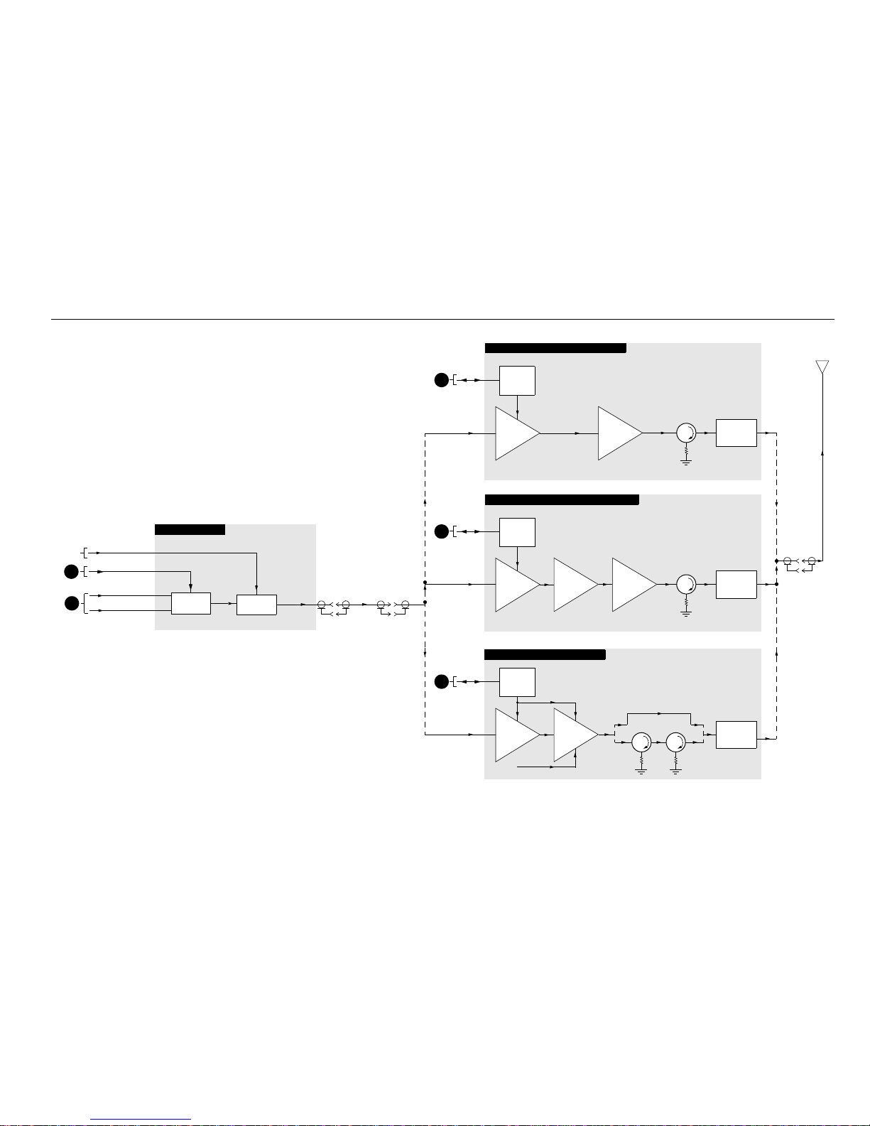
75 W POWER AMPLIFIER (800 & 900 MHz)
B
SPI BUS
POWER
CONTROL
CIRCUITRY
TWO CIRCULATORS
50 OHM
LOAD
15 W
INTERMEDIATE
POWER AMP
50 W
BUTTERFLY
MODULE
LOW-PASS
FILTER/
DIRECTIONAL
COUPLER
B
SPI BUS
POWER
CONTROL
CIRCUITRY
CIRCULATOR
50 OHM
LOAD
10 W
INTERMEDIATE
POWER AMP
LOW-PASS
FILTER/
DIRECTIONAL
COUPLER
DUAL
DEVICE
MODULE
100 W POWER AMPLIFIER (<600 MHz)
B
SPI BUS
POWER
CONTROL
CIRCUITRY
Figure 3. MTR2000 Station Functional Block
Diagram (Sheet 2 of 2)
50 OHM
LOAD
OR
OR
30 W & 40 W POWER AMPLIFIER
PA ENA BLE
Page 28

INSTALLATION
1 PRE-INSTALLATION CONSIDERATIONS
Proper installation ensures the best possible performance and reliability of the station equipment. Pre-installation
planning is required. This includes considering the mounting location of the equipment in relation to input power, antennas, and telephone interfaces. Also to be considered are site environment conditions, the particular
mounting method (several available), and required tools and equipment.
If this is the first time installing this type of equipment , it is hig hly recommended that the user read:
• this entire installation section before beginn ing the actual installation, an d
• the Motorola Quality Standards Fixed Network Equipment Installation manual, R56 (68P8108 9E50); specifically refer to the information on ground connection for lightning protection.
Installation Overview
The following information is an overview for installing the station and ancillary equipment. Step-by-step procedures for each of the major installation tasks are then provided beginning in Section 2, Mechanical
Installation.
• Plan the installation, paying particula r atten tion to environmental
conditions at the site, ventilation requirements, and grounding and
lightning protection.
• Unpack and inspect the equipment
• Mechanically install the equipment at the site
• If a Wireline Interface Board or an Auxiliary I/O Board is included
with the station, configure the board jumpers for required operation
• Make necessary electrical and cabling con nections, including the following:
- AC input cabling
- Coaxial cables to transmit and receive antennas
- Phone line con nections
-System cables
Motorola Inc., 2005
All Rights Reserved
Printed in U.S.A.
Government & Enterprise Mobility Solutions
1301 E. Algonquin Road, Schaumburg, IL 60196
68P81096E37-N
06/28/05-UP
Page 29

Installation
Note
STOP
IMPORTANT
• Perform a post-installation functional checkout test of the equipment
to verify proper installation
• Proceed to the Optimization procedures to customize the station parameters per customer specifications (e.g., operating frequency, PL,
codes, etc.)
Regulatory requirements may require the use of an optional high stability
reference for some modes of operation. It is recommended that the user
check current local regulations prior to operation.
Environmental Conditions at Intended Installation Site
If the station is to be installed in an environment which is unusually
dusty or dirty (and so does not meet the air quality requirements), the
air used to cool the station modules must be treated using appropriate
filtering devices. Dust or dirt accumulating on the internal circuit
boards and modules is not easily r emoved, a nd can cause such malf unctions as overheating and intermittent electrical connections.
Operating T emperature
Range
Humidity Not to exceed 95% relative humidity @ 50°C (122°F).
Air Quality For equipment operating in an environmentally controlled environment
The station may be installed in any location suitable for electronic communications equipment, provided that the environmental conditions do not
exceed the equipment specifications for temperature, humidity, and air
quality. These are:
–30°C (–22°F) to +60°C (+140°F)
This is the temperature measured in close proximity to the station. For example, if the station is mounted in a cabinet, the temperature within the
cabinet would be measured.
with the station(s) rack mounted, the airborne particulates level must not
exceed 25 µg/m
For equipment operating in an area which is not environmentally controlled (station(s) cabinet mounted), the airborne particulates level must
not exceed 90 µg/m
3
.
3
.
2 68P81096E37-N
06/28/05
Page 30

Equipment Ventilation
STOP
IMPORTANT
CAUTION
!
Installation
The high-power (100/75W) stations are equipped with cooling fans that
are used to provided forced convection cooling.
When planning the installation, observe the follo wing ventilation guidelines:
Mounting the MTR2000
in a Cabinet
• Customer-supplied cabinets must be equipped with ventilation slots
or openings in the front (for air entry) and back or side panels (for air
to exit). If several stations are installed in a single cabinet, be sure ventilation openings surround each station to allow for adequate cooling.
• All cabinets must have a least 15cm (6in) of open space between the
air vents and any wall or o ther cabinets. This all ows adequate air flow.
• When multiple cabinets (each equipped with several stations) are installed in an enclosed area, make sure the temperature within each
cabinet does not exceed the recommended / maximum operating temperature of +60°C (+140°F). It may be necessary to have air conditioning or other climate control equipment installed to satisfy the
environmental requiremen ts.
High Power Stations: The mounting o f only O NE STATION PER CABINET is recommended. More t han on e stati on per ca binet w ill result in
degradation of thermal specifications at high ambient temperatures.
Low Power Stations: In order to maintain thermal specifi cation of –30°C
(–22°F) to +60°C (+140°F), the low power stations must be mounted in a
cabinet with additional cool ing. A single low power stati on mounted in
a cabinet without additional cooling, will operate at thermal specification performance of –30°C (–22°F) to +54°C (+129°F).
Appropriate precautions should be taken to ensure that st ation ambient
temperature does not exceed +60°C (+140°F).
If multiple stations are required, AND THERMAL SPECIFICATION
DEGRADATION IS ACCEPTABLE, the following is recommended
when no cabinet fans are used. Up to three stations can be mounted in
a 76.2cm (30in) or larger cabi net with two rack units of spacing between
each station. This will result in t hermal specification perfo rmance of
–30°C (–22°F) to +40°C (+104°F).
Mounting the MTR2000
in a Rack
68P81096E37-N 3
06/28/05
When mounting multiple stations in a rack, ensure that the minimum
spacing between stations is:
• 3 rack units (13.3cm or 5.25in) for VHF and UHF low power stations,
and 350MHz stations.
• 1 rack unit (4.4cm or 1.75in) for VHF and UHF high power stations,
800MHz stations, and 900MHz stations.
This spacing needs to be complied with to ensur e that the thermal rating
of the station is not exceeded.
Page 31

Installation
CAUTION
!
AC Input Power Requirements
The station is equipped with a switching power supply, this assembly operates from 85 Vac
prong line cord is supplied to connect the power supply to the ac source.
It is recommended that a standard 3-wire grounded electrical outlet be
used as the ac source.
The ac socket-outlet must be instal led near the equipment and must be
easily accessible.
The outlet must be connected to an ac source capable of supplying a maximum of 1020 VA. For a nominal 110/120Vac input, the ac source must
supply 8.5A and should be protected by a circuit breaker rated at 15A. For
a nominal 220/24 0Vac input , the ac sour ce must suppl y 4.25A and should
be protected by a circuit breaker rated at 10A.
to 264 Vac at 47 to 63 Hz ac input power. A standard 3-
Requirement for
European Union (EU)
Countries
Beginning January 1, 2001, input harmonic current specifications were
changed for most electronic telecommunication equipment installed in EU
countries. Accordingly, power factor correction is necessary for MTR2000
stations.
Power Supply models DLN6 622 and DLN6624 h ave internal power fa ctor
correction.
4 68P81096E37-N
06/28/05
Page 32

Equipment Mounting Methods
Installation
The station equipment may be mounted in a rack or cabinet (available as
options).
The station can b e shi p pe d:
• …in an floor-mount indoor cabinet. Each floor-mount cabinet has
front and rear vented doors and has the capacity to hold a minimum
of a single station (see thermal limitations described under Equipment Ventilation), and required ancillary equipment. The larger cabinets provide additional room for supplementary peripheral
equipment.
• …in a rack. Open frame racks accept multiple stations and ancillary
equipment; EIA 48.3cm (19 in) rack configuration.
68P81096E37-N 5
06/28/05
Page 33

Installation
STOP
WARNING
Floor-mount Cabinet
The physical dimensions for all available floor-mount cabinets are shown
in Figure 2. All dimensions are common to all cabinets, except for cabinet
height. The cabinet options and associated he ight are:
Cabinet Option Height
X52AF 76.2cm (30in)
X308AD 1.168m (46in)
X180AC 1.524m (60in)
Minimum recommended clearances are 76.2cm (30in) front and 91.44 cm
(36in) rear for minimum installation access. Refer to Equipm ent Ventilation for recommended ventilation clearances.
For improved access to the unit, a tray slide is available; option X 968AA.
Ensure that the cabine t is securely anchored to the floor, thereby avoiding possible equipment tipping and personal injury. Refer to Mounting
Procedures – Mounting Flo or -mount Ca binets fo r details on pr oper ca binet installation.
6 68P81096E37-N
06/28/05
Page 34

Installation
5.1 cm
(2 in)
5.1 cm
(2 in)
5.1 cm
(2 in)
9.6 cm
(3.8 in)
5.1 cm
(2 in)
5.1 cm
(2 in)
Figure 1. Floor-mount Cabinet – Dimensions and Clearances
55.9 cm
(22 in)
46.5 cm
(18.3 in)
45.2 cm
(17.8 in)
55.9 cm
(22 in)
46.5 cm
(18.3 in)
FRONT
Mounting
Rails (4)
76.2 cm
(30 in)
0.64 cm
(0.25 in)
FRONT VIEW SIDE VIEW
BASE MOUNTING DETAIL
VIEWED FROM
TOP
5.1 cm
(2 in)
49 cm
(19.3 in)
5.1 cm
(2 in)
9.6 cm
(3.8 in)
5.1 cm
(2 in)
9.2 cm
(3.625 in)
holes (2)
1.575 cm
(0.62 in)
holes (4)
1.524m
(60 in)
1.168m
(46 in)
49 cm
(19.3 in)
Station
Support
Brackets (2)
68P81096E37-N 7
06/28/05
Page 35

Installation
Note
Modular Racks
The rack options, associated height and available number of racking units
are:
Rack Option Rack Height
Number of
Racking Units
X741AF 76.2cm (30in) 16
X742AF 1.143m (45in) 24
X743AF 1.32m (52 in) 27
The physical dimensions and clearances for all available modular racks are
shown in Figure 2. The top and bottom plates are identical. All dimensions and clearances are common to all racks, except for the 2 dimensions
identified below. The rack options and associated dimensions are:
Rack Option Dimension A Dimension B
X741AF 79.2cm (31.2in) 26.1cm (10.27in)
X742AF 1.147m (45in) 27.25 cm (10.73in)
X743AF 1.28m (52in) 31.15cm (12.26in)
Recommended clearance front and rear is 91.44cm (36in) minimum for
servicing access. Refer to Equipment Ventilation for recommended ventilation clearances.
FRU kit CLN6679A (MTR2000 Rack Mounting Hardware) is included
with each Rack Option. This allows proper installation of the MTR2000
station within the rack’s centre of gravity.
This kit includes two rack mount standoffs and eight mounting screws.
8 68P81096E37-N
06/28/05
Page 36

Installation
Figure 2. Modular Rack – Dimensions and Clearances
9.22cm
(3.63 in)
1.59cm
(0.625in)
20.58cm
(8.1in)
76.2cm
(3in)
Dimension BDimension B
17.78cm
(7in)
3.81cm
(1.5in)
17.78cm
(7in)
7.22cm
(2.85in)
38.74cm
(15.25in)
5cm
(2in)
15.9mm Diam
(0.625in)
9.4mm Diam
(0.37in)
52.7cm
(20.75in)
45.36cm
(17.86in)
48.77cm
(19.2in)
38.74cm
(15.25in)
13.45cm
(5.3in)
5cm
(2in)
9.4mm Diam
(0.37in)
Rack Center
SIDE VIEW
TOP / BOTTOM
VIEW
Dimension BDimension B
Dimension BDimension A
10.97cm
(4.375in)
13.21cm
(5.25in)
0784384T03
13.21cm
5.25in
Standoff
68P81096E37-N 9
06/28/05
Page 37

Installation
STOP
IMPORTANT
Note
Site Grounding and Lightning Protection
Site Grounding Lightning Protection Recommendations
Proper site grounding and lightning protection are vitally important
considerations. Failure to provide proper lightning protection may result in permanent damage to the radio equipment.
One of the most important considerations when designing a com munications site is the ground and lightning protection system. While proper
grounding techniques and ligh tning protection are closely related, the
general category of site grounding may be divided as follows:
Electrical Ground Ground wires carrying electrical current from circuitry or equipment at
the site is included in the category of electrical ground. Examples include
the ac or dc electrical power used to source equipment located at the site,
telephone lines, and wires or cables connected to alarms or sensors located
at the site.
RF Ground This type of ground is related to the transmission of radio frequency ener-
gy to earth ground. An example of rf grounding is the use of shielding to
prevent or at least minimize the leakage o f unwanted rf transmissions
from communications equipment and cables.
Lightning Ground Providing adequate lightning protection is critical to a s af e and reliable
communications site. Telephone lines, rf transmission cables, and ac and
dc power lines must all be protected to prevent lightning energy from entering the site building.
Although a comprehensive coverage of site grounding techniques and
lighting protection is not within the scope of this manual, there are several
excellent industry sources for rules and guidelines on ground and lightning protection at communications sites.
Motorola recommends the following reference source:
Motorola Quality Standards Fixed Network Equipment
Installation manual, R56. . . . . . . . . . . . . . . . . . . . . . . . . . . . .68P81089E50
Equipment Grounding Guidelines
10 68P81096E37-N
The station is equipped with a ground screw located on the rear of the station Power Supply module. This screw is used to connect the station to the
site ground point. It is assumed that all telephone lines, antenna cables,
and ac or dc power cabling has been properly grounded and lightning protected by following the rules and guidelines provided in the above reference.
06/28/05
Page 38

Recommended Tools and Equipment
Note
STOP
WARNING
In addition to the typical compliment of hand tool s, the following tools
and equipment are recommended for proper installation of the station
equipment.
• Tarpaulin or plastic drop cloth or cover surrounding equipment
while drilling concrete anchor holes (for in stallations where cabinet
or rack is being anchored to concrete).
• Vacuum cleaner for removing concrete dust caused by drilling.
Equipment Unpacking and Inspection
The station equipment may be shipped by either air freight or electronic
van (as specified by customer), except where noted.
Installation
Cabinet Unpacking
• If no cabinet or rack is desired, the station is shipped in a box; the station is positioned between pieces of cushioned corrugated cardboard.
• All available cabinets are shipped with the station(s) installed in the
cabinet, with the cabinet bolted to a wooden skid and covere d with a
cardboard box with corrugated interior corner braces.
• Stations to be used in open frame racks are shipped with the station
and ancillary equipment mounted in the rack and covered by an antistatic plastic bag. All rack shipments are electronic van only.
Thoroughly inspect the equipment as soon as possible a ft er delivery. If
any part of the equipment has been damaged in transit, immediately report the extent of the damage to the transportation company and to Motorola.
Antistatic plastic bags should be kept for future shipping/transporting of
station.
68P81096E37-N 11
06/28/05
When a station (mounted in a cabinet) is delivered from Motorola, it arrives in suitable packing materials. If the unpacked equipment is dam-
aged, return it to Motorola in its original packaging.
Equipment should be handled in its original pa ckaging unti l it is deliv -
ered to its final destination. If the equipment is damaged while being
moved without the original packaging, the warranty claim is not valid.
Page 39

Installation
2 MECHANICAL INSTALLATION
STOP
IMPORTANT
STOP
IMPORTANT
STOP
WARNING
This section describes the procedures to unpack and mechanically install the sta tion equipment. A variety of
mounting methods are possible, depending on whether a cabinet or rack (if any) has been selected to house the
station(s). Installation procedures are provided for each of the cabinet and rack types, as well as the slide rail.
Be sure to observe proper electrostatic discharge precautions if modules
must be removed from the station.
Unpacking Equipment
Introduction
Station equipment packing methods vary depending upon the type of optional rack or cabinet selected by the customer. Unpacking procedur es for
these various methods are provided in the following paragraphs.
The equipment must be immediately inspected for damage after unpacking, and a report of the ext ent of a ny damage made to the transportation company and to Motorola.
Unpacking Stations
The station is shipped in a carton, cushioned by four plastic inserts at the
corners of the carton.
Improper handling of the station may cause personal injury or damage
to the station. DO NOT pick up the station by holding the Preselector
(if so equipped). Use the handl es on the front of the sta tion, or the Power Supply and Power Amplifier casings when picking up the station.
Front Panel – Removal and Replacement
Remove station front panel by inserting a small flat-blade screwdriver into
one of two access holes at either end of the panel and, by carefully moving
the handle of the screwdriver away fro m the center , release the fr ont panel
locking clip from the chassis and pull away the panel
Replace station front panel by inserting one of the front panel locking clips
into corre sponding latc h on the station ho using, and car efully pre ssing the
panel on the opposite side until the second locking clip snaps into place.
.
12 68P81096E37-N
06/28/05
Page 40

Installation
Unpacking Floor-mount Cabinets
The floor-mount cabinets are shipped mounted to a wooden skid, secured
with corrugated corner braces held by a plastic strap, and covered with a
cardboard cover. Unpack the equipment as described in Figure 3.
68P81096E37-N 13
06/28/05
Page 41

Installation
Figure 3. Unpacking Procedures - Floor-mount Cabinets
1. Remove cardboard cover from station.
2. Cut band as shown.
3. Remove top packing spacer and
corrugated corner supports.
4. Remove antist at ic bag . Do not discard bag,
it will be reinstalled to protect equipment
during installation.
5. Depending on cabinet type, either open or
remove front and rear doors to gain access to
the four (4) bolts securing the station to the
wooden skid. Remove the bolts and nuts as
shown.
6. Use hoist to lift the station from the skid.
Remove skid and return station to floor.
7. Replace antistatic bag over station to
provide protection during installation.
Cardboard
Cover
Corrugated
Corner
Supports
Wooden
Skid
Cut This
Band
Top Packing
Spacer
Antistatic Bag
Wooden
Skid
Station
Cabinet
14 68P81096E37-N
06/28/05
Page 42

Mounting Procedures
Installation
Introduction
In most cases, stations are shipped in the selected cabinet or rack (i.e., the
station is mounted and cabled), and may be installed by following the procedures below. However, the following three scenarios require special
mounting procedures:
• Customer plans to mount equipment in customer-supplied rack or
cabinet, and orders equipment to ship from the factory without a rack
or cabinet.
• Customer orders two stations in a single rack.
• Customer requires slide rail assembly.
Installing Racks
In a typical installation, the rack is bolted to a concrete floor to provide stability.
The following procedure describes the steps necessary to bolt the rack to a
concrete floor . Be sure to check with local authorities to verify that the following procedure conforms to local building codes and regulations before
permanently installing the rack.
1. Carefully align the rack at the desired anchoring location.
2. Use the rack mounting foot as a template and mark the location of the
six 19mm (3/4in ) dia meter mounting holes. All six anchoring positions must be used.
3. Move the rack aside, drill holes in the concrete floor, and install the
mounting anchors (RAM RD-56 anchors recommended) per instructions provided with the anchors. Make sure that none of the anchors
comes in contact with the reinforcing wire mesh buried in the concrete; the rack must be electrically isolated fr om any other equipment
or materials at t he site.
4. Align the rack with the installed anchors and lightly secure the rack
to the floor using the proper mounting hardware. Do not tighten the
mounting hardware at this time.
5. Check the vertical plumb of the rack. Also check that the top is level.
Use shims (flat washers or flat aluminum plates) as necessa r y unde r
the rack mounting foot to achieve vertical plumb and horizontal
level.
68P81096E37-N 15
06/28/05
6. Tightly secure the rack to the floor anchors making sure that it remains vertically plumb and horizontally level.
7. After all debris is removed a nd cemen t dust is cleared away , remove
whatever protective covering has been placed on the equipment, including the antistatic bag.
Page 43

Installation
CAUTION
!
Note
Cement dust from concrete flooring is harmful to el ectronic equi pment
and wiring. Make sure that the rack and any collocated equipment are
protected prior to drilling holes in the concrete floor. Use a tarpaulin,
cloth, or plastic sheeting to cover exposed equipment. (The rack should
be already covered wit h an anti static bag; do not remove the bag at this
time.) Use a vacuum while drilling the holes to minimize th e spread o f
concrete dust. Carefully clean up any accumulated dust and debris from
the anchor installation before uncovering the equipment.
Mounting Floor-mount Cabinets
Each cabinet bottom is pre-drilled with four (4) mounti ng holes to allow
attachment to the site floor. If installing on a concrete floor, use the cabinet
as a template, mark the hole locations, and follow the procedures above for
anchoring equipment racks. If in stalling on a wooden floor, use lag bolts
and washers (customer supplied) to secure the cabinet to the floor.
Transferring Equipment from Shipping Container to Rack
or Cabinet
As mentioned under Equipment Unpa ckin g an d Ins pecti on, a s t ation can
be shipped in a box. Upon delivery , the equipment must be removed from
the container and transferred to a Motorola-supplied rack or cabinet, or to
a customer-supplied rack or cabinet.
Customer-supplied cabinets and racks must have mounting rails and hole
spacing compatible with EIA Universal 48.3cm (19in) specifications. Cabinets must provide adequate ventilation (as detailed under Equipment
Ventilat ion) and must meet the following criteria:
- 41.3cm (16.25in) deep
-48.3cm (19in) wide
- 13.4cm (5.25in) high
- Two mounting rails 5cm (2in ) from front of cabinet with front mounting holes 5.7 cm (2.25in) apart ( c enter to center).
Contact Motorola Engineering for specific questions regarding mounting
equipment in customer-supplied cabinets.
16 68P81096E37-N
06/28/05
Page 44
Installation
Note
Note
Installing Slide Rail Assembly in a Motorola Cabinet
Referring to Figure 4, perform the following procedure to install slide rail
option X968AA.
On a bench-top, working
on one side of the slide rail
assembly at a time…
1. Remove the Inner-Slide Rail from the slide assembly (left and right)
by depressing the Slide Locking Latch and sliding the Inner-Slide Rail
out from the slide assembly.
2. Install the Inner-Slide Rail (left) on the Power Supply side by:
- removing the 2 bottom screws from the station power supply
EMI cover, and
- in sta lling the Inner-Slide Rail (left) with the supplied screws.
3. Install the Inner-Slide Rail (right) on the PA side using the holes in the
PA casing .
4. Attach each Outer-Slide Rail to a Cabinet Bracket with supplied
screws.
The left and right Cabinet Brackets are identical.
The Locking Ta b of each Outer-Slide Rail must face towards the rear
of the cabinet.
Working in the cabinet… 5. The cabinet must have a set of vertical cabinet rails in the back as well
as the front. If there is no set in the back, these must be installed. The
back rail is installed the same as the front rail, with the supplied
screws.
6. Install each assembled Cabine t B r acket (with attached Outer-Slide
Rail) to the appropriate side of the cabinet.
The U-shaped cutout of the Cabinet Bracket must face up.
7. Slide the station (with an Inner-Slide Rails mounted on each side) into
the Outer-Slide Rails in the cabinet; an audible snap is heard. Continue sliding the station in until the station is fully seated.
8. Secure the station to the cabinet front rails with the supplied screws.
68P81096E37-N 17
06/28/05
Page 45

Bracket Screws;
6mm panhead (4)
Locking Tab
(towards back of
cabinet)
Outer-Slide Rail
Mounting Screws;
countersunk (2)
Inner-Slide Rail
Mounting Screws;
panhead (2),
station side
Inner-Slide Rail
Outer-Slide Rail
Cabinet
Bracket
Cabinet
Rail, front
Note
The left-side slide rail assembly is shown,
as viewed from the front of the cabinet.
The left side is a mirror image of the right
side.
Slide Locking
Latch
Cabinet
Rail, rear
Direction
That Station
Slides Out
L
E
F
T
Note: Middle-Slide Rail
not shown (for clarity).
Installation
Figure 4. Slide Rail Installation; Option X968AA (Left Side Shown)
18 68P81096E37-N
06/28/05
Page 46

Installation
Note
Installing Slide Rail Assembly in a Non-Motorola Cabinet
Referring to Figure 5, perform the following procedure to install slide rail
option X346AB .
On a bench-top, working
on one side of the slide rail
assembly at a time…
1. Remove the Inner-Slide Rail from the slide assembly (left and right)
by depressing the Slide Locking Latch and sliding the Inner-Slide Rail
out from the slide assembly.
2. Install the Inner-Slide Rail (left) on the Power Supply side by:
- removing the 2 bottom screws from the station power supply
EMI cover, and
- in sta lling the Inner-Slide Rail (left) with the supplied screws.
3. Install the Inner-Slide Rail (right) on the PA side using the holes in the
PA casing .
4. Attach each Outer-Slide Rail to the cabinet Brackets with supplied
screws. Only use the lower slot of each bracket. Leave the screws
loose; they will tightened when the brackets are mounted in the cabinet (step 7).
The left and right Cabinet Bracket sets are identical.
The Locking Ta b of each Outer-Slide Rail must face towards the rear
of the cabinet.
Working in the cabinet… 5. Install a cage nut in line with clearance hole in Threaded Strip prior
to fitting the Front Bracket to the front cabinet rail.
This nut is required for mounting the station (in step 9).
The cage nuts are provided with the cabinet.
6. Fit the Short Bracket and Long Bracket (with attached Outer-Slide
Rail) to the Front and Rear Cabinet Rails using the Bracket Mounting
Screws and Threaded Strips.
7. Tighten the Outer-Slide Rail hardware after positioning the OuterSlide Rail front side in line with the inner surface of the Front Cabinet
Rails.
8. Slide the station (with an Inner-Slide Rails mounted on each side) into
the Outer-Slide Rails in the cabinet; an audible snap is hea rd.
Continue sliding the station in until the station is fully seated.
9. Secure the station to the Front Cabinet Rails with the supplied Station
Mounting Screws.
68P81096E37-N 19
06/28/05
Page 47

Installation
Locking Ta b
(towards back
of cabinet)
Outer-Slide Rail
Mounting
Hardware sets; (4)
Inner-Slide Rail Mounting
Screws; panhead (2 ),
station side
Inner-Slide Rail
Outer-Slide
Rail
Note
The left-side slide rail assembly is shown, as
viewed from the front of the cabinet. The left
side is a mirror image of the right side.
Direction
That Station
Slides Out
Station
Mounting
Screws; (2)
Mount Outer-Slide Rails
to Brackets; ONLY use
lower slot of Brackets.
Long Bracket
Short Bracket
Install a cage nut in line with
clearance hole in Threaded Strip
prior to fitting bracket to the front
cabinet rail.
This nut is required for mounting
the station.
The cage nuts are provided with
the cabinet.
Threaded
Strip
Front
Cabinet Rail
Rear
Cabinet Rail
Bracket
Mounting
Screws; (4)
L
E
F
T
Note: Middle-Slide Rail
not shown (for clarity).
Figure 5. Slide Rail Installation; Option X346AB (Left Side Shown)
20 68P81096E37-N
06/28/05
Page 48
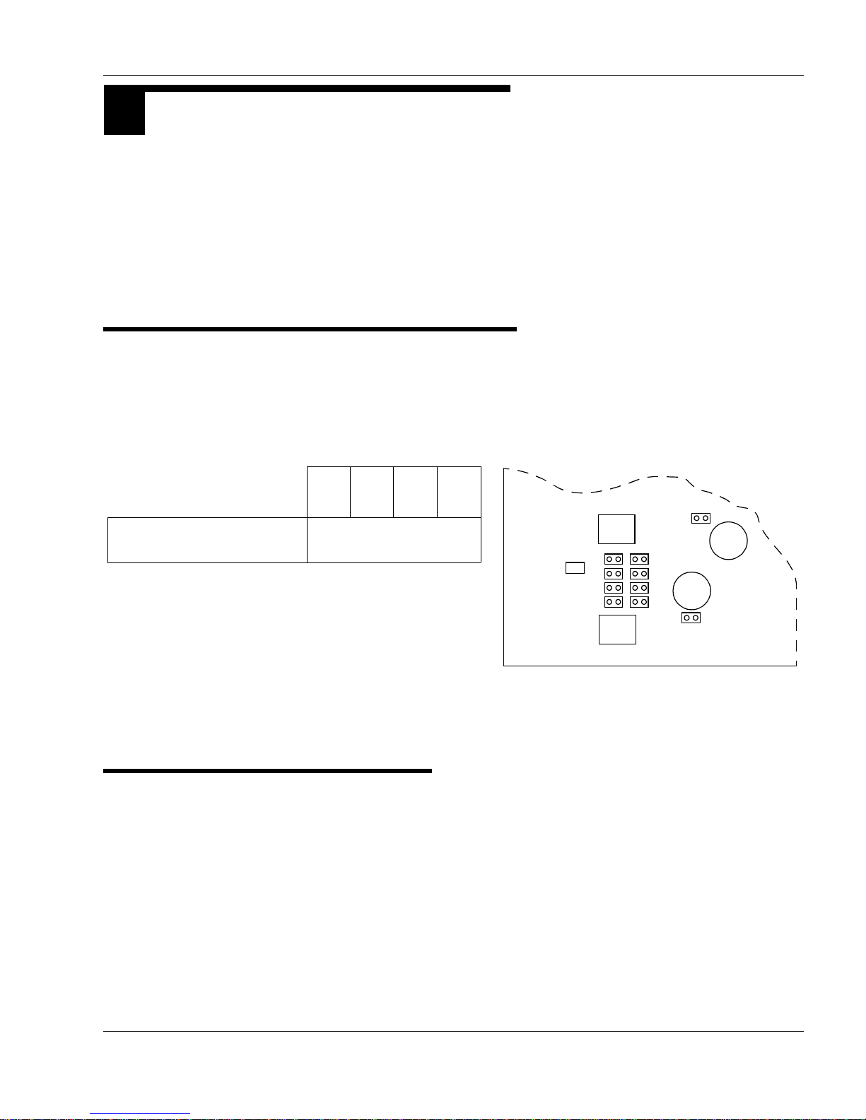
Installation
3 BOARD CONFIGURATION
C84
T1
T2
C15
C74
P11
P15
P13
P17
P10
P14
P12
P16
P6
P2
Figure 6. CLN1203 Wireline Interface Board Jumper Settings
P10,
P11
P12,
P13
P14,
P15
P16,
P17
Tone Remote Control
2-wire/4-wire configurations
out
Most station configuration parameters are altered through the Radio Service Software (RSS) with the exception of
some parameters for the following boards, which are configured through jumpers:
• 4-Wire Wireline Interface Board (CLN1203),
• 4-Wire Euro Wireline Interface Board (CLN1204),
• Auxiliary I/O Board(CLN1206).
4-Wire Wireline Interface Board
Model CLN1203 WIB supports tone control of the station. CLN1203 provides a fixed impedance of 600Ω to the wireline. Figure 6 shows the jumper locations for tone control.
.
4-Wire Euro Wireline Interface Board
68P81096E37-N 21
06/28/05
Figure 7 shows the correct settings of impedance matching jumpers for the
model CLN1204 WIB, as determined by the country in which the station is
being operated. Incorrect jumper settings may violate local telecommunications authority regulations and place the equipment in an unapproved
status. Some countries al so specify a maximum allowed line input level.
Refer to the RSS Online Help, under Line Level.
Page 49

Installation
P1, P5, P8, P9
Country
Reference
Impedance
A * B C D E P3, P7
Australia √√
Spain √√
Austria √√
Germany (2-wir e) √√
Luxemburg √√
South Africa √√
Switzerland √
Belgium √√
Cyprus √√
Former USSR √√
Former Yugoslavia √√
Germany (4-wir e) √√
Greece √√
Italy √√
Netherlands √√
Portugal √√
Denmark √√
Ireland √√
UK √√
Finland √√
France √√
Norway √
Sweden √
120ηF
72ηF
600Ω
115ηF
115ηF
115ηF
Figure 7. CLN1204 Wireline Interface Board Jumper Settings
C74
T1
T2
C15
C84
P3
E D C B A
P7
P1
P9
P5
P8
E D C B A
E D C B A
E D C B A
√ = Jumper In
A = Pin 1 connects to Pin 2
* This setting represents a
standard 600 ohm matching
and is the factory default.
B = Pin 3 connects to Pin 4
C = Pin 5 connects to Pin 6
D = Pin 7 connects to Pin 8
E = Pin 9 connects to Pin 10
Canada and the U.S wir eline requirements are
supported by Wireline
board model CLN1203.
Note
820Ω
220Ω
220Ω
115ηF
820Ω
150Ω
830Ω
400Ω
330ηF
500Ω
370Ω
310ηF
620Ω
820Ω
220Ω
220Ω
220Ω
820Ω
820Ω
30ηF
900Ω
22 68P81096E37-N
06/28/05
Page 50

Auxiliary I/O Board
Figure 8. CLN1206 Auxiliary I/O Board Jumpers
P5
P9
P6
P2
P3
P4
P1
13
4 2
4 2
13
2 1
10 9
2 4
1 3
2 4
1 3
P8
10 9
2 1
P7
10 9
2 1
Installation
Jumpers are provided to r oute inputs and outputs in a specific direction to
and from the SCM; the SCM determines the functionality of the inputs and
outputs.
The board jumpers are shown in Figure 8.
GPI_14 is a special input which can be jumpered to be a transistor input or
opto isolated. In addition it can be dedicated to the Ext_PTT* Line routed
to the SCM. This function is a fast external PTT* (an active low function).
The board jumper settings for P2, P9, P6 are provided in Table 1. Settings
for P5 are provided in Table 2. Settings for P3, P4 are provided in Table 3.
P7 and P8 are not used.
68P81096E37-N 23
06/28/05
Page 51

Installation
Notes
CAUTION
!
Function on
GPI_14
Table 1. Configuring Input GPI_14 Function
Auxiliary I/O Board Jumper s
System
Input Type
Connector
Input Pins
P2 P9
P6
(See Note 1)
via Optocoupler (E/M sub).
Fast External PTT*
Fast External PTT
Function on GPO_14 Output Type
AC Fail via Relay Closure B29, A30 2 - 4
SPI Latch for GPO_14 (software defined) via Relay Closure B29, A30 1 - 2
(See Note 2)
via Tra nsistor B26 9 - 10, 7 - 8 In
via Optocoupler (E/M sub) A29 Opto +
via Tra nsistor B26 9 - 10, 7 - 8 Out
Table 2. Configuring Output GPO_14 Function
The shaded areas indicate default manufacturing settings.
A29 Opto +
A26 Opto –
A26 Opto –
3 - 4, 1 - 2 In
3 - 4, 1 - 2 Out
System Connector (J5)
Output Pins
Auxiliary
I/O Board
Jumper P5
Note 1: This is an active low; that is, no current to the Opto Input.
Note 2: This configuratio n, with P6 out (PTT when current to the Opto
Input) represents the E Signal of 4 wire E&M Tr unk T ype I Phone
Signalling. The opposite direction of the E&M is covered in
Note 3.
In this configuration the second re maining unused input type
must be jumpered to the SPI Buffer. The Buffer Input should
never be left floating; otherwise the IRQ Generator will not
function properly (i.e., use either P2-1&2 or P9-7&8).
24 68P81096E37-N
06/28/05
Page 52

Table 3. Configuring Output GPO_15 Function
Notes
Function on GPO_15 Output Type
System Connector (J5)
Output Pins
Installation
Auxiliary I/O
Board Jumpers
P3 P4
Fast Carrier Detect
RdStat
SPI Latch for GPO_15 (software defined)
via Relay Closure C3, B3 2 - 4 2 - 4
via Open Collector B21 (see Note 4) 3 - 4 2 - 4
via Relay Closure
C3, B3 2 - 4 1 - 3
(see Note 3)
via Open Collector B21 (see Note 4) 3, 4 1, 3
via Relay Closure C3, B3 1 - 2
via Open Collector B21 (see Note 4) 1 - 3
Note 3: This configuration represents the M Signal of 4 wire E&M T runk
Type I Phone Signalling. The opposite direction of the E&M is
covered in Note 2.
Note 4: Indicates that the configuration is only available when the board
is plugged into Option slot 1.
68P81096E37-N 25
06/28/05
Page 53

Installation
4 ELECTRICAL CONNECTIONS
STOP
IMPORTANT
When installing option boards,
ensure that an Electro-Static
Discharge (ESD) cable is
connected (via banana plug) to
the hole in the front-right
handle of the station when
installing option boards.
Otherwise, the option boards
may be damaged.
ESD Connect
After the station equipment has been mechanically installed, electrical connections must be made. This involves
making the following connections to:
• power supply,
• antenna coax cables,
•system cables, and
• telephone lines.
There are also electrical connections associated with maintenance and troubleshooting of the station. These connectors are located on the front of the Station Control Module (see Station Operation section for position of these
connectors).
26 68P81096E37-N
06/28/05
Page 54

Figure 9 shows the position of the station external connectors located at the rear of the station.
Figure 9. Location of External Connectors at Rear of Station
Battery Backup and
DC Input Connector
Rx RF
Connector
Tx RF
Connector
Wireline
Connector
System
Connector
Trunking / MRTI
Connector
AC Power Connector
(Not used in DC mode)
Ground
Screw
Installation
68P81096E37-N 27
06/28/05
Page 55

Installation
CAUTION
!
CAUTION
!
Power Supply Connections
AC Input Power Connection
Do not apply ac power to the station at this time. Ma ke sure that the circuit breaker associated with the ac outlet is turned to OFF.
The ac socket-outlet must be instal led near the equipment and must be
easily accessible.
Each station is shipped with an 2.5m (8ft) 3-conductor line cord. Figure 9
shows the ac line cord connector. Insert the plug into an appropriate
grounded outlet.
The North American line cord is equipped with a NEMA 5–15 plug, intended for 110/120Vac operation.
The optional European line cord (Option X189AA) is equipped with a
“Schuko” style CEE VII (7) plug, intended for 220/240VAC operation.
Plugs for other countries are available as the followin g options:
Location Option Number
U. K. X162AD
Australia X191AD
If an alternate line cord is required, obtain a line cord employing “HAR”
fl exi ble cord with fittings app ro ved by t he s afety tes tin g ag ency in th e end-
use country.
28 68P81096E37-N
06/28/05
Page 56

Installation
CAUTION
!
CAUTION
!
STOP
WARNING
CAUTION: See
manual before
removing cover.
STOP
WARNING
Ground Connection
The station is equipped with a ground screw located on the r ear of the station Power Supply module. Connect the ground screw to the site ground
point.
Refer to Motorola Quality Standards Fixed Network Equipment Installation manual, R56 (68P81089E50) for complete information regarding
lightning protection.
The station is to be connected to a battery supply that is in accordance
with the applicable electrical codes for the end use country; for example,
the National Electrical Code ANSI/NFPA No. 70 in the U.S.
DC Input Power Connection
For DC-only operation, the DC source power is connected to the station
through the battery backup connector shown in Figure 9, and described in
“Battery Connection” on page 29.
Ensure that the appropriate voltage is connected; that is,
Nominal 14.2 Vdc (10.8 to 16.0 Vdc) for a low power station, or
Nominal 28.6 Vdc(21.0 to 32.0 Vdc) for the high power station.
Battery Connection
Battery backup interface offers the capability of connecting to battery
backup power in the event of an AC power line failure.
The battery backup system is connected to the
station through the red and black connector
mounted at the rear of the station. The connector
has a cover with the following label. This label directs the technician to read the information provided below:
This battery backup system must have, at a minimum, a disconnect relay
controlled by an AC fail detector.
DO NOT connect a battery directly to the station. Damage to batteries
as well as to the station may occur. Batteries must be connected to the
station through an Argus Technologies Battery Rev erting Charger, Model #010-519-20 (Motorola Model #L1883) for 12V charging systems, and
Argus Technologies Model #010-523-20 (Motorola Model #L1884) for
24V charging systems. These systems were developed specifically for
this interface and tested by Motoro la for proper station operati on. Dam-
68P81096E37-N 29
06/28/05
Page 57

Installation
CAUTION
!
Figure 10. Making Connections to Storage Battery
DC input Connector located at
rear of the station for hooking up
the Battery backup system.
Required input power:
• Voltage - 14.2 Vdc Low Power (LP)
28.4 Vdc High Power (HP)
• Current - 11.5 Amps LP
13.0 Amps HP
Both positive a nd negative terminals m ust be
protected with appropriate fast acting fuses.
Secondary circuitry must be SELV type and
be installed nearby, preferable in the same
building.
All installatio ns shall be carried o ut by trained
service per sonnel only.
Connector ESD
cover must be in
place when Battery
Backup cable is not
in use – to prevent
exposure to live
contacts.
CAUTION
!
age resulting from use of any other charging systems will void the warranty. Refer to qualified sales/service repres entative f or charger
ordering information.
The station is to be connected to a battery supply that is in accordance
with the applicable electri cal codes for the end use country; for examp le,
the National Electric Code ANSI/NFPA No.70 for the U.S.
Cables are supplied with the charging option. Do not make connections
directly from the station to the storage battery. Connect as shown in
Figure 10.
30 68P81096E37-N
06/28/05
Page 58

RF Antenna Connections
Installation
The transmit and receive antenna rf connections are made using two separate N-type connectors. Coax cables from the receive an d transmit antennas must be connected to the two N-type connectors. The position of these
connectors is shown in Figure 9.
In the case where an optional Antenna Relay is used on the station, the
coax cable from the single transmit/receive antenna is connected to the
middle N-type connector of the Antenna Relay.
68P81096E37-N 31
06/28/05
Page 59

Installation
System Cable Connections
System connections are made through one or both of the following connectors:
- the Trunking/MRTI connector and
- the System connector.
Trunking/MRTI
Connector
The location of the Trunking/MRTI connector and System connector on
the station rear panel is shown in Figure 9.
The following cables are available for trunking system applications:
- 7.62m (25ft) Trunk Cable, part # 3083765X04
- 15.24m (50ft) Trunk Cable, part # 3083765X05
- 22.86m (75ft) Trunk Cable, part # 3083765X06
- 30.48m (100ft) Trunk Cable, part # 3083765X07
The following cable is available for MRTI applications:
- Interface cable for Zetron model 30, kit # TTO4097
System Connector The cable connected to the System connector can be configured for various
system options.
A generic System cable is available for variety of applications such as Wild
Card, Main Standby, and Auxiliary In put/Output:
- generic System cable, kit # TKN9205A
This cable provides a housing shell for connection to the 96 pin backplane
connector, 30 loose pins, and a quantity of 30 of 24 gauge wires (2 meter
long with a pin for header on one end and un terminated at the other end).
Table 4 provides a description of commonly used System Connector pins.
32 68P81096E37-N
06/28/05
Page 60

Table 4. System Connector – Commonly Used Pins
Pin Function
Name Description
Installation
Pin # Pin Signal Characteristics
RdStat TTL compatible logic output
indicating Rx. Activation
C2, B21,
B3/C3
0.0 to 0.2Vdc with squelched receiver,
4.8 to 5.2Vdc with unsquelched receiver.
status.
Disc. Rx.
Audio
RSSI DC output volts related to
Unfiltered and unsquelched
discriminator audio without
de-emphasis.
received carrier level.
C17 80mV minimum to 400mV maximum for
60% system deviation. Output level is RSS
programmable.
C11 Typically 0.5Vdc for –120dBm to 3.5 Vdc
for –40 dBm carrier. Variation with carrier
level @ approximately 40mV/dBm.
Cntrl
14.2V
14.2 volts dc output.
For dc-only 250W power
A18, B18, C18
C32, B32, C32
Total current through all of th ese p ins
should not exceed 1Amp.
supplies, this voltage is equal
to the input supply voltage.
5 V 5.1 ± 0.25 volts dc output. A20, B20, C20 Total current through all of these pins
should not exceed 500 mA.
GND Ground. A19, B19, C19
A27, B27, C27
Total current through all of th ese p ins
should not exceed 1.5 Amp.
A31, B31, C31
Aux.Tx
Audio
Tx. modulation input from
external source.
A17 RSS programmable sensitivity.
For R03.01 (host software) and earlier, the
fixed sensitivity is @ 172 mVrms for 60%
system deviation.
RSS programmable for pre-emphasized
or flat response. DC offset +2.4V. High
impedance input.
Ext. PTT External Tx. keying signal. C10 Grounding Ext. PTT pin causes Tx to key.
AC_Fail Logic output to indicate failure
of AC line input.
Wireline
Pair 3+/–
Wireline
Additional wireline for other
functions.
Pair 4+/–
68P81096E37-N 33
06/28/05
5.0Vdc on pin when Tx is not keyed.
Note: To transmit signalling code (PL /
DPL) by external PTT, it should be mapped
(via RSS) to Wireline, and external modula-
tion input should be routed to wireline.
A4 Requires a Battery Revert dc supply. Line
goes high (5.0Vdc) if AC fails.
C28, C30
Line sensitivity and operation identical to
B28, B30
line pairs 1 and 2 (see Table 10).
Page 61

Installation
Note
Table 5 provides a summary of the Auxiliary Inputs / Outputs (Wildcard
I/O) currently available through the System Connector.
Table 5. Summary of Auxiliary Inputs/Outputs at the System Connector
Auxiliary I/O
GPI_…
System
Connector (J5) Pin
Auxiliary I/O
GPO…
System
Connector (J5) Pin
3A5 0 A12
4C5 2 A11
7A22 8 A1
9 A28 RX Lock B1
10 C12 TX Lock C1
11 B12 13 B2
12 B11 15 B21
13 B9 15 (relay) C3, B3
See Table 3, on
page 25, and B3, C3
in T able 7, on page 36
and Table 8, on
page 37.
Details of the System connector pinouts are provided in:
- Table 7, Row A pin assignments
- Ta b le 7, Row B pin assignments
- Table 8, Row C pin assignments
The following symbols and abbreviations are used in Tables 7 to 8:
* = line is Active Low
NS = Not Supported; this pin should not be used.
Aux I/O = Indicates that the Aux I/O board must be present for
this functionality.
WCI = Wild Card Input
WCO = Wild Card Output
The RSS Online Help provides the most current information on the System
Connector pin assignments.
34 68P81096E37-N
06/28/05
Page 62

Table 6. J5 SYSTEM CONNECTOR, Row A Pins
Installation
Pin # Pin Assignment
1 GPO_8 (WCO) O J1-C32, J2-C32 OCO, 100mA, 40V
2 PA Fail (Aux I/O) O J1-C31, J2-C31 OCO, 100mA, 40V, active low
3 SCI_CLCK 1 O J1-C30, J2-C30, J3-C28 Do not use.
4 AC Fail O P8-5, J1-C29, J2- C29, J3-C24 TTL out p ut, ac t ive high
5 GPI_3 (WCI) I J1-C28, J2-C28 Pu ll ed up tr an sistor input, 16V max
6 GP1_15 (
7 Ext Failsoft (Aux I/O) I J1-C26, J2-C26
8 GPI_1 (NS) I J1-C25, J2-C25
9 GPI_2 (NS) I J1-C24, J2-C24 Pulled up transistor input, 16V max
10 VSWR_Fail* (Aux I/O) O J1-C23, J2-C23
11 GPO_2 (WCO) O J1-C22, J2-C22
12 GPO_0 (WCO) O J1-B25, J2-B25
13 Antenna Relay O P10-1, J3-C26 OCO, 200mA , act iv e low
14 Not Supported O J1-C18, J2-C18, J3-C19
15 Spare 310 – –
16 Spare 308 – –
17 Aux TX Audio I J1-C16, J2-C16, J3-C16 RSS programmable input sensitivity
18 Cntrl 14.2 VDC O P8 pins 3, 4 (thru F2) +14.2Vdc, Not e 1
19 GND – Station ground
20 5 VDC O P8 pins 7, 8 +5.1 ± 0.25 Vdc
21 Not Supported O J3-C12
22 GP1_7 (WCI) I J1-C11, J2-C11 Pulled up transistor input, 16V max.
23 Spare 323 – –
24 Spare 320 – –
25 Spare 903 – –
Ext PTT or GP1_14 (
26
Note 2
27 GND – Station ground
28 GPI_9 (WCI) or GPO_3 (NS) I/O J1-C6, J2-C6
29 Ext PTT or GPI_14 (
30 AC Fail or GPO_14, Note 3 O J1-C4, J2-C4 One side of normally ope n relay, see B29
31 GND – Station ground
32 Cntrl 14.2 VDC O P8 pins 3, 4 (thru F2) +14.2Vdc, Not e 1
Note 1: For dc-only 250W power supplies, this voltage is
Note 2: This pin can be jumpered for Ext PTT (supported)
–) (NS) I J1-C27, J2-C27 Negative side opto-isolated input, see C7
–),
+), Note 2 I J1-C5, J2-C5 Positive side opto-isolated input, see A2 6
equal to the input supply voltage
or GPI_14 (not supported). See Aux I/O jumpers
P2 and P9.
Input/
Output
I J1-C7, J2-C7 Negative side opto-isolated input, see A29
.
To/F rom Signal Cha r act eristics
Pulled up transistor input, 16V max
Pulled up transistor output (10kohms to +5Vdc), active
low
Pulled up transistor output (10kohms to +5Vdc)
Caution: See Auxiliary I/O section for jumpering in formation
Note 3: This pin can be jumpered for AC Fail
(supported) or GPO_14 (not supported).
See Aux I/O jumper P5.
68P81096E37-N 35
06/28/05
Page 63

Installation
Table 7. J5 SYSTEM CONNECTOR, Row B Pins
Pin # Pin Assignment
1 RX Lock (A ux I/O) O J1-B32, J2-B32 OCO, 100mA, 40V; active high
2 GPO_13 (WCO) O J1-B31, J2-B31 OCO, 100mA, 40V
3 RdStat or G P O_15, Note 4 O J1-B30, J2-B30 O ne si de of n ormally open relay, see C3
4 Carrier Detect Switch O J1-B29, J2-B29, J3-B24 TTL output, active high
5 GPI_ 8 (NS) I J1-B28, J2-B28
7 Ext Repeat* (Aux I/O) I J1-B26, J2-B26
8 Trunk Duplex Enable* I J3-B25 TTL input
9 GPI_13 (WCI) or GPO_7 (NS) I/O J1-B24, J2-B24
10 Spare 311 – N/C
11 GPI_12 (WCI) or GPO_6 (NS) I/O J1-B22, J2-B22
12 GPI_11 (WCI) or GPO_5 (NS) I/O J1-B23, J2-B23
13 Spare 301 – N/C
14 Not Supported I J1-B19, J2-B19, J3-B19 TTL input
15 GND – Station ground
16 Spare 300 – –
17 Spare 321 – –
18 Cntrl 14.2 VDC O P8 pins 3, 4 (thru F2) +14.2Vdc, Note 1
19 GND – Station ground
20 5 VDC O P8 pin s 7, 8 +5.1 ± 0.25 Vdc
21 RdStat or GPO_15, Note 4 O J1-B12 OCO, 100mA, 40V
22 Spare 322 – –
23 Spare 325 – –
24 Spare 309 – –
25 Spare 902 – –
26 Ext PTT or GPI_14, Note 2 I J1-B7, J2-B7 Pu lle d up tr an sistor input, 16V max, see A29
27 GND – Station ground
28 Line 4+ O J4-C10 Wireline outp ut balanced , (+)
29 AC Fail or GPO_14, Note3 O J1-B4, J2-B4 O ther side of normally open relay, see A30
30 Line 4– O J4-A9 Wireline outp ut balanced , (–)
31 GND – Station ground
32 Cntrl 14.2 VDC O P8 pins 3, 4 (thru F2) +14.2Vdc, Note 1
Note 4: This pin can be jumpered for RdStat (supported) or GPO_15 (supported). See Aux I/O jumpers P3 and P4.
Input/
Output
To/From Signal Characteristics
Pulled up tran sistor input, 16V m ax6 GPI_ 5 (NS) I J1-B27, J2-B27
Caution: See Auxiliary I/O section for jumpering information
Caution: See Auxiliary I/O section for jumpering information
36 68P81096E37-N
06/28/05
Page 64

Table 8. J5 SYSTEM CONNECTOR, Row C Pins
Installation
Pin # Pin Assignment
1 TX Lock (Au x I/O) O J1-A32, J2-A32 OCO, 100mA, 40 V; active high
2 Rdstat-R2 Control O J1-A31, J2-A31, J3-A 26 TTL output, high when unsque lc h e d
3 RdStat or G P O_15, Note 4 O J1-A30, J2-A30 Other side of normally op en relay, see B3
4 Failsoft Output (Aux I/O) O J1-A29, J2-A29 OCO, 100mA, 40V, active low
5 GPI_4 (WCI) I J1-A 28, J2-A28 Pull ed up t ran si st or in put , 16V max
6 Rx Inhibit I J1-A27, J2-A27, J3-B26 TTL input; active low
7 GPI_15 (
8 Trunk TX Inhibit* I J3-A25 TTL input
RF Relay Control Out
9
(Aux I/O)
Ext PTT* Out (Aux I/O),
10
Note 5
11 RSSI O J1-A22, J2-A22, J3-A22
GPI_10 (WCI) or
12
GPO_4 (NS)
13 Spare 304 – –
14 Not Supported O J1-A19, J2-A19, J3-A19
15 GND – Station ground
16 GND – Station ground
17 Disc RX Audio O J1-A16, J2-A16, J3-A16
18 Cntrl 14.2 VDC O P8 pins 3, 4 (thru F2) +14.2Vdc, Note 1
19 GND – Station ground
20 5 VDC O P8 pins 7, 8 +5.1 ± 0.25 Vdc
21 Not Supported O J3-A12
22 Spare 302 – –
23 Spare 324 – –
24 GPIO_0 (CNTR I/O) I/O J1-A9, J2-A9, J3-A17 TTL input/output
25 Spare 317 – –
26 Spare 901 – –
27 GND – Station ground
28 Line 3+ I J4-C12 Wireline input balanced, (+)
29 GPIO_1 (CNTR I/O) I/O J1-A4, J2-A4, J3-A13 TTL input/output
30 Line 3– I J4-A11 Wireline input balanced, (–)
31 GND – Station ground
32 Cntrl 14.2 VDC O P8 pins 3, 4 (thru F2) +14.2Vdc, Note 1
Note 5: Ext PTT signal output, taken from Ext PTT input. The output signal can be inverted, depending on jumper settings.
+) (NS) I J1-A26, J2-A26 Positi ve side opto-isolated input, see A6
See jumpers P2, P6, P9.
Input/
Output
O J1-B5, J2-B5 OCO, 200mA, 40V, active high
I J1-A23, J2-A23, J3-A23 TTL input
I/O J1-A24, J2-A24
To/From Signal Characteristics
Typically 0.5Vdc for –120dBm to 3.5 Vdc for –40 dBm carrier. Variation with carrier level @ approximately 40mV/
dBm.
Caution: See A u xiliary I/O secti on for jumpering information
Discriminator audio, flat response; 80mV to 400 mV for
60% deviation
68P81096E37-N 37
06/28/05
Page 65

Installation
Telephone Line Connections
Introduction
In conventional systems where the station is controlled by a remote console, or in wide area systems utilizing comparators, phone lines must be
connected between the station and the remote equipment. The phone
lines may carry analog voice, or encoded voice. Also carried on the phone
lines are T one Remote Control (type of remote control signalling). The following info rmati on def ine s the sp ecif icatio ns fo r the ph one li nes, the loc ation on the station backplane for phone line connections, and which of the
four (4) wireline circuits to use for various system types.
38 68P81096E37-N
06/28/05
Page 66

Installation
Telephone Line Specifications
Most telephone companies recognize either “3002” or “Type 5” as designations to define phone line types and associated electrical specifications.
Telephone lin es meeting the specifications for either of these types are acceptable for use with the station. Table 9 shows the specifications for
“3002” or “Type 5” phone line types.
Table 9. Type 5 and “3002” Phone Line Specifications
Parameter
Type 5
Specification
3002
Specification
Loss Deviation ±4.0dB ±4.0dB
C–Notched Noise 51dBmCO 51dBmCO
Attenuation Distortion:
504 to 2504 Hz
404 to 2804 Hz
304 to 3004 Hz
Signal To C–No tched Noise
–2.0 to +8.0 dB
–2.0 to +10.0dB
–3.0 to +12.0dB
–2.0 to +8.0 dB
–2.0 to +10.0dB
–3.0 to +12.0dB
≥24dB ≥24dB
Ratio
Envelope Delay Distortion:
804 to 2604Hz 1750µsec 1750 µsec
Intermodulation Distortion:
R2
R3
≥27dB
≥32dB
≥25dB
≥30dB
Phase Jitter:
20 to 300Hz
4 to 300Hz
≤10 Degrees
≤15 Degrees
≤25 Degrees
≤30 Degrees
Frequency Shift ±3Hz ±5Hz
68P81096E37-N 39
06/28/05
Page 67

Installation
CAUTION
!
Wireline Connector When 4-wire (2 line) telephone connections are required, Line 1 and Line 2
Location of Telephone Line Connections
are provided through the 4–position wire wrap terminal connector.
Table 10 provides a description of the Wireline connector line pair assignments.
Table 10. Wireline Connector Line Pair Assignments
Line Pair Functionality
1 +/– Tx wireline input for 4 wire configuration.
Input level is programmable by RSS between 0 dBm to
–50 dBm.
Do not use this line pair for 2 wire wireline
configuration.
2 +/– Rx wireline output for 4 wire configuration.
Output level is programmable between +7 dBm to
–20 dBm for 100% deviation.
Use this line pair for 2 wire wireline configuration.
Connector 4 has 8 holes:
- the round holes are for wire insertion, and
- the square holes are for insert release.
This wire-trap terminal connector accepts only 0.52 sq mm (20 AWG) to
0.2 sq mm (24 AWG); solid wire or stranded wire with a tin topcoat. Wir es
inserted into the connector should be stripped to length 9.53mm (0.375 in).
As a removal release tool, use either:
- a stripped wire of any of above sizes, or
- the Wireline connector tool, part number 6600809D00.
Before applying excessive pullout force on the telephone connection
wires, be sure to release wires properly.
System Connector When 8-wire (4 line) telephone connections are required:
- Line 1 and Line 2 are provided through the 4-terminal Telephone connector.
- Line 3 and Line 4 are provided through the System connector.
The location of the Telephone and System connectors on the station rear
panel is shown in Figure 9.
40 68P81096E37-N
Table 4 describes the System connector pin assignments for Line Pairs 3
and 4.
06/28/05
Page 68

System Type vs. Wireline Circuit
Note
Note
T able 11 shows which of the four (4) wireline circuits to use for various system types.
Stations equipped with a 4–wire Wireline Interface can support a single 4–
wire or a single 2–wire telephone line connection.
Stations equipped with an 8–wire Wireline Interface can for example support a two 4–wire or a single 2–wire telephone line connection.
Table 11. System Types vs. Wireline Circuit Matrix
Installation
System Type
Line 1
(Note i)
Line 2
(Note i)
Line 3 Line 4
Conventional Local Area Analog Console Console Not used Not used
Conventional Wide Area Analog Comparator or
Comparator Not used Not used
Console
Trunked Local Area Clear, without CPI CIT CIT Not used Not used
Trunked Local Area Clear, with CPI Console Console CIT CIT
Trunked Wide Area Clear without CPI Comparator Comparator Not used No t used
Trunked Wide Area Clear, with CPI Console Console Comparator Comparator
Trunked AMSS Clear Comparator Comparator Not used Not used
Redundant Trunking Clear, Wide Area
Comparator Comparator Not used Not used
without CPI
i) For 4–wire systems, Line 1 is transmit audio (landline to station),
and Line 2 is receive audio (station to landline). For 2–wire systems,
Line 2 is transmit and receive audio.
ii) A CPI is a Console Priority Interface.; used in Trunking systems.
A CIT is a Central Interconnect Terminal; used in T runking systems.
68P81096E37-N 41
06/28/05
iii) Transmit audio with respect to consoles, comparators, CIT, and
DVM modems are outputs.
Tran smit audio with respect to stations is an input.
iv) Receive aud io with r espect to consoles , comparat ors, CIT, and DVM
modems are inpu t s.
Receive audio with respect to stations is an output.
Page 69

Installation
Station Maintenance Connections
T able12 provides a de scriptio n of the main tenance c onnectio ns located on
the front of the Station Control Module.
Table 12. Station Maintenance Connections on the SCM
Connector
Name
5/10MHz
External
Reference Signal
(J5603)
Function Details
External
Reference signal
for internal
system clock
5MHz or 10MHz external
reference may be used.
Select desired frequency
through RSS. High impedance
input. Minimum level is 1Vpp
for either type of input.
Maximum level should not
exceed 3Vpp.
Service Speaker
(P5601)
Output to Power
Voice speaker
Adjustable between 0 to
500mV across 1Kohm @60%
system deviation. Audio signal
appears between pins 3 and 4
on the connector. Must use
speaker type HSN1000 via
adapter cable Part.No.
0185180U01.
RSS (P5600) Serial Port For connection to serial port of
a computer via cable Part No.
3082056X02. The R adio Se rvice
Software (RSS) application is
run on the computer.
42 68P81096E37-N
Microphone
(P5602)
Local
Microphone
Input
Use local microphone type
GMN6147 or equivalent.
Modulation sensitivity for 60%
system deviation is typically
300mV. This microphone
should be equipped with 3
control buttons for speaker
volume control, Rx. monitor
and Intercom control functions.
06/28/05
Page 70

Installation
5 POST INSTALLATION CHECKLIST
CAUTION
!
After the station equipment has been mechanically installed and all electrical connections have been made, power
may now be applied and the station checked for proper operation.
Applying Power
Before applying power to the station, make sure all boards are securely
seated in the appropriate connectors on the backplane and that all rf cables
are securely connected.
Turn ON the circuit breaker controlling the ac outlet that is supplying
power to the station Power Supply M od ule, or switch on the DC-supply
to a station with a DC-only Power Supply Module.
Changing Fuse To replace the station fuse:
1. Turn off station power at source (e.g., ac breaker).
2. Remove fuse cover plate located on the backplane shield by unscrewing one M4 screw.
3. Pull defective fuse carefully with small needle nose pliers.
4. Replace new fuse (part # 6583049X16) carefully with small needle
nose pliers.
For continued protection of the station against risk of fi re, repl ace
the fuse only with the same type and rating of fuse.
5. Restore power to the station.
68P81096E37-N 43
06/28/05
Page 71

Installation
FS
FS
FS
Verifying Proper Operation
Operation of the station can be verified by:
• observing the state of the 4 LEDs located on the front panel
• listening to audible alarms, and
• exercising radio operation.
Some station components can become extremely hot during station operation. Turn off a ll power to the s tation, and wait until sufficiently coo l
before touching the station.
Front Panel LEDs
After turning the station power ON (or after a station reset), the 4 LEDs on
the station front panel:
1. Are all lit for about 3 seconds to indicate that they are functional.
The St ation St atus LED appear s yellow since both the red a nd green
LEDs of this bicolor indicator are lit at the same time.
2. All go off for about 15 seconds.
3. All stay off except for the Station Status LED which goes red for
about 6 seconds.
4. Now indicate operational status of the station. The 4 LEDs in dicate:
- PA Keyed LED; green – station PA is keyed.
- FailSoft LED; yellow – (if set up for trunking) station is not be-
ing controlled from the trunking central controller.
- Rx Active LED; green – station is unsquelched.
- Station Status LED; red/green – operational status of station.
Station
Status
LED
This two-color Station Status LED (i.e., red or green) indicates the following:
LED Color LED State Indicates that the…
Off Off 5V power is not present
Red On Station is Not Operational –
major failure
Red Flashing Station is Operational but Not
Fully Functional – minor failure
44 68P81096E37-N
Green On Station is Operating Normally
Red/Green Al ternately Flashing Station is in Boot Mode
Green Flashing Station is in Service Mode
06/28/05
Page 72

Installation
CAUTION
!
CAUTION
!
FS
A major failure renders the station unusable. These failure could be
caused by one of the following conditions:
- Rx or Tx synthesizer out of lock
- PA failure,
- Sharp (i.e., 10 dB) rf power cutback,
- self test failure
A random flashing of the Station Status LED indicates major failure of
the Station Control Module; since a control module reset turns the LED s
on.
A minor failure limits the functionality of the station. These failures could
be caused by one of the following conditions:
- ac source power failure
- exciter or receiver analog metering voltage degradation
- wireline loopback failure
- invalid local channel selection
Boot mode is the mode the station is in during the loading of software into
the station’s Flash memory.
RX Active
LED
Service mode is the mode the station is in during normal maintenance and
service periods. These modes include the following conditions:
-Intercom - PL Disable
- Access Disable - Failsoft Disable
- Power Control Disable - Service PTT
The Radio Service Software (RSS) can be used to determine which failure
or service modes are active.
Service mode indicates that the station is not fully functional.
This RX Active LED indicates the following:
LED Color LED State Indicates that the…
Green On Receiver is active.
This LED is lit when receive activation criteria (user defined) are satisfied;
i.e., the radio is unsquelched.
68P81096E37-N 45
06/28/05
Page 73
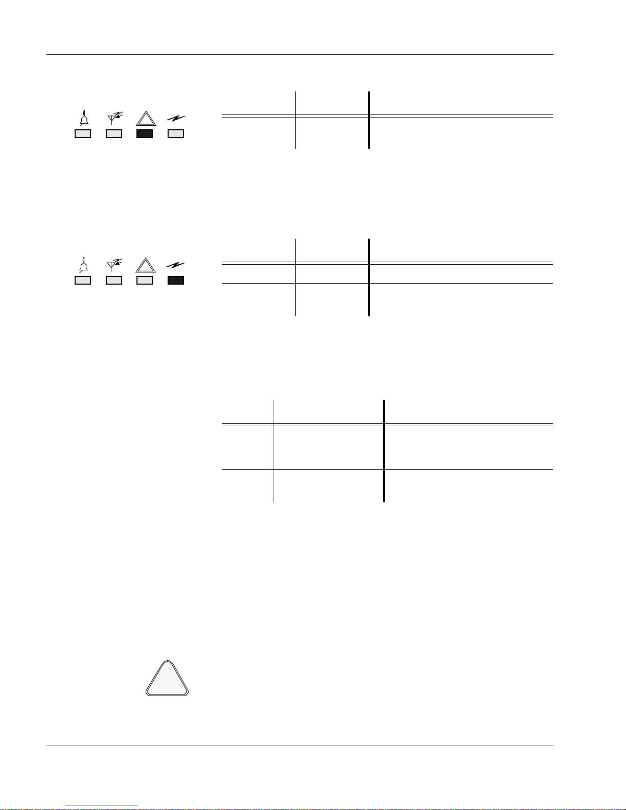
Installation
FS
FS
CAUTION
!
FailSoft
LED
PA Keyed
LED
This FailSoft LED indicates the following:
LED Color LED State Indicates that the …
Yellow Flashing statio n is in the Trunking system
Failsoft mode.
This LED is lit when no activity is detected on the transmit data signal
from the trunking central controller; the station is in Failsoft mode. This
condition usually indicates a failed link to the trunking central controller.
This PA Keyed LED indicates the following:
LED Color LED State Indicates that the …
Green On PA is keyed.
Green Flashing PA is keyed, but operating with
power cutback.
Listening For Audible Alarms
With a Service Speaker connected to the station (see Station Operation,
Service Connections), any active audible alarms can be heard.
Alarm Sound Indicates that …
AC Fail a single short beep a station configured with DC-
revert has detected an AC power
failure.
PA Fail two short beeps the station has been keyed, and the
Power Amplifier has failed.
The audible alarms ar e repeated e very 10 secon ds. If mor e than one ala rm
is active, they are offset by 2 seconds.
Exercising Radio Operation
Operation of the station radio can be verified by exercising the radio’s twoway operation. This may be carried out when an external speaker and microphone are connected to th e Station Control Module (SCM).
The kit # for the speaker is HSN1000. The external speaker requires an
adaptor cable, part # 0185180U01.
Using a speaker other than the recommended HSN1000 may result in
the station blowing a fuse.
46 68P81096E37-N
The kit number for the microphone is GMN6147B.
06/28/05
Page 74

Installation
6 OPTIMIZATION
CAUTION
!
CAUTION
!
After the station and ancillary equipment have been mechanically installed, properly cabled, and power applied,
the equipment must then be optimized; that is, before placing the station in operation. Optimizing is performed
through the Radio Service Software (RSS), kit number RVN4148.
After the station is operational, the stat ion’s codeplug data must be copied to a PC- compatible computer.
In order to program an MTR2000 station for Trunking operation, kit
number RVN4148C (or later) of the RSS must be used. The current version is available through the U.S. and Canada Americas After market Division (AAD).
Optimizing Tasks
Optimization involves the following tasks:
1. Reading the station codeplug from the station (this ensures a match
between the station serial number (resident in the codeplug) and the
serial number (part of the customized station codeplug data) that is
written back to the station (see task 5).
2. Customizing the station codeplug and savin g the da ta to the station
3. Aligning the station for:
- Rx Wireline
-Tx Wireline
- Receiver RSSI calibration (option)
- Receiver Squelch Adjust
4. Perform ing post-optimization procedures.
5. Writing the customized codeplug to the station codeplug.
For details on these tasks, refer to the Optimizing a New Installation topic of
the Radio Service Software (RSS) Online Help.
Copying Station Codeplug Date To a PC-compatible Computer
68P81096E37-N 47
06/28/05
A copy of each station’s codeplug data must be made on an IBM-PC
compatible computer . This is done through the Radi o Service Software
(RSS). See the RSS Startup Manual, 68P81096E15.
Page 75

Installation
7 INSTALLING STATION HARDWARE OPTIONS
When a station is ordered with an Antenna Relay or External Preselector option, the respective module is attached
to the station when delivered.
When a statio n is ordered with an External D o uble Circulat or option, this circulator is provided in a peripheral
tray.
In the case where an option is later added to the station, it can be installed according to the information provided
in the Ancillary Equipment sections of the appropriate Instruction manual. Also refer to the Troubleshooting section for information on tuning the External Preselector.
48 68P81096E37-N
06/28/05
Page 76

STATION
1 DESCRIPTION
OPERATION
This section describes the LED indicators and connectors provided on the station.
The set of LEDs indicate the operational status of the station.
There are two sets of connectors for devices external to the station:
• One set connects to external devices to enable full operation of the station. These are located at the back of
the station.
• Another set connects to external devices for servicing the station. These are located on the Station Control
Module.
Motorola Inc., 2005
All Rights Reserved
Printed in U.S.A.
Government & Enterprise Mobility Solutions
1301 E. Algonquin Road, Schaumburg, IL 60196
68P81096E38-D
06/28/05-UP
Page 77
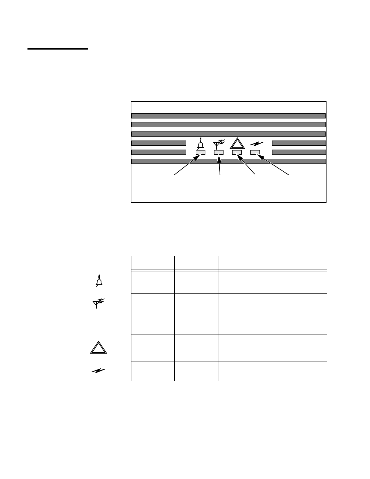
Station Operation
Red/Green
Statio n Status LED
Yellow
FailSoft LED
Green
Rx Active LED
Figure 1. Front Panel LEDs
Green
PA Keyed LED
FS
FS
LED Indicators
A set of 4 LEDs is located on the station front panel. The position of the 4
LEDs on the front panel is shown in Figure 1. These LEDs indicate the status of the station during normal operation.
For further information on the states indicated by these LEDs, refer to the
INSTAL LA TION section, Post Installation Checklist, V er ifying Proper Operation.
Function Color Indicates …
Station
red / green … operational status of station.
Status
Rx Active green … th at th e station Rx activation
criteria are satisfied. This could be:
- RF carrier only,
- PL/DPL only, or
- RF carrier plus PL/DPL.
FailSoft yellow … (if set up for trunking) that the
station is not being controlled from
the trunking central controller.
PA Keyed green … that station PA is keyed.
2 68P81096E38-D
06/28/05
Page 78

External Device Connections
Station Operation
Refer to INSTALLATION, Electrical Connections for the position of the
station external connectors and line cord, located on the back panel.
A BNC connector on the front of the SCM allows the station to be connected to a 5 MHz or 10 MHz external reference signal.
Figure 2 shows the position of the BNC connector on the SCM.
68P81096E38-D 3
06/28/05
Page 79
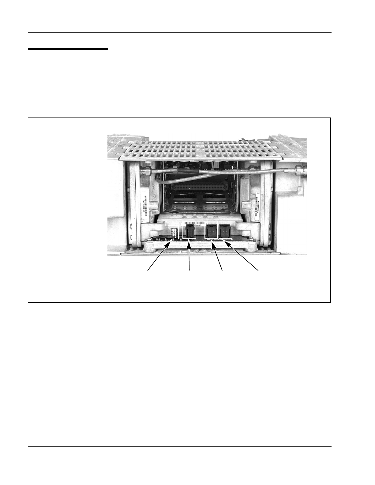
Station Operation
Figure 2. SCM Connectors
5/10MHz External
Reference Signal
Service
Microphone
RSSService
Speaker
Front of station
with Front Panel
removed.
Service Connections
Service ports and LEDs are located on the front of the Station Control
Module (SCM).
Figure 2 shows the position of the connectors on the SCM.
4 68P81096E38-D
The service ports include connectors for:
- 5/10 MHz External Reference Signal
- Service Speaker:
connects between the telephone connector on the Station Control
Module and an external speaker/amplifier (with a 6 pin molex co nnector) via an adaptor cable; part number 0185180U01.
- RSS:
connects between the telephone connector on the Station Control
Module and the DB9 connector on a PC. A DB25 connector can also
be used to connect to the PC, when used with a DB25-DB9 adaptor.
- Service Microphone:
connects between the telephone connector on the Station Control
Module and a service microphone.
06/28/05
 Loading...