

Page 1

MOBILE RELEASE 15.0
MTP8550Ex
Feature User Guide
OCTOBER 2015
© 2015 Motorola Solutions, Inc. All rights reserved
*MN002041A01*
MN002041A01–AA
Page 2

Page 3

MN002041A01–AA
Contents
Contents
List of Figures............................................................................................................15
List of Tables............................................................................................................. 17
Copyrights................................................................................................................. 19
Chapter 1: General Information............................................................................... 21
1.1 Safety Information..................................................................................................................21
1.2 Icon Conventions................................................................................................................... 21
1.3 Using this Guide.................................................................................................................... 21
1.4 Feature and Service Availability............................................................................................ 22
Chapter 2: Getting Started........................................................................................23
2.1 Product Technical Information............................................................................................... 23
2.2 Before Power On................................................................................................................... 23
2.2.1 Attaching the Antenna..............................................................................................24
2.2.2 Installing the SIM Card.............................................................................................24
2.2.3 MicroSD Card.......................................................................................................... 28
2.2.4 Installing the MicroSD Card..................................................................................... 29
2.2.5 Installing the Battery................................................................................................ 32
2.2.6 Removing the Battery.............................................................................................. 33
2.2.7 Charging the Battery................................................................................................ 33
2.2.8 Charging Indicators..................................................................................................34
2.2.9 Low Battery Indication..............................................................................................35
2.3 Controls and Indicators..........................................................................................................36
2.4 Display................................................................................................................................... 38
2.4.1 Configurable Idle Screen......................................................................................... 39
2.5 Status Icons........................................................................................................................... 40
2.6 Powering On the Radio..........................................................................................................45
2.7 PIN Code Authentication....................................................................................................... 45
2.7.1 Unblocking Your Radio............................................................................................ 45
2.8 Unlocking Your Radio............................................................................................................ 45
2.9 Locking/Unlocking the Keys/Buttons..................................................................................... 45
2.10 Holding Your Radio..............................................................................................................46
2.11 Entering TMO / DMO Mode................................................................................................. 46
2.12 Transmit Inhibit Mode.......................................................................................................... 47
2.13 Selecting Talkgroups........................................................................................................... 47
2.14 Talkgroup Icon Selection..................................................................................................... 48
2.15 Using Timed Talkgroup Change.......................................................................................... 48
Send Feedback 3
Page 4

MN002041A01–AA
Contents
2.16 Broadcast Call..................................................................................................................... 48
2.17 Private Call
2.17.1 Making Private Calls.............................................................................................. 49
2.18 Ambience Listening (AL) Call.............................................................................................. 49
2.19 One-Touch Button Feature.................................................................................................. 50
2.20 Terminal Temporary Disable/Enable................................................................................... 52
2.21 Terminal Permanent Disable............................................................................................... 52
2.22 High/Low Audio Toggle........................................................................................................52
2.22.1 Using High Audio................................................................................................... 52
2.22.2 Using Low Audio.................................................................................................... 53
2.23 During the Call..................................................................................................................... 53
2.24 Writing Text..........................................................................................................................53
2.24.1 Selecting Text Entry Modes................................................................................... 53
2.24.2 Selecting Text Entry Methods and Languages...................................................... 54
2.24.3 Text Entry Icons..................................................................................................... 54
2.24.4 Keys Usage............................................................................................................55
2.24.5 Writing in iTAP Alphanumeric................................................................................ 56
2.24.6 Writing in TAP Alphanumeric................................................................................. 57
2.24.7 Word Locking......................................................................................................... 58
2.24.8 Adding Words to the Dictionary............................................................................. 58
2.25 Home Display Text Message...............................................................................................58
.......................................................................................................................... 49
Chapter 3: Modes...................................................................................................... 59
3.1 Using Networks......................................................................................................................59
3.2 Trunked Mode Operation.......................................................................................................59
3.2.1 Entering TMO Mode.................................................................................................59
3.2.2 Making Group Calls in TMO.....................................................................................60
3.2.3 Receiving Group Calls in Idle...................................................................................60
3.2.4 Receiving Group Calls during Ongoing Group Calls................................................60
3.2.5 Dynamic Group Number Assignment (DGNA).........................................................60
3.2.6 DGNA Reception..................................................................................................... 61
3.2.7 DGNA Auto Select Group........................................................................................ 61
3.2.8 DGNA Auto Reselect Group.................................................................................... 61
3.2.9 Viewing DGNA Talkgroups...................................................................................... 61
3.2.10 Broadcast Calls Initiated by Users......................................................................... 61
3.2.11 Initializing Broadcast Calls..................................................................................... 62
3.2.12 Phone and PABX Calls.......................................................................................... 62
3.2.13 Assistance Call...................................................................................................... 62
3.2.14 Call Modification.....................................................................................................62
3.3 Local Site Trunking................................................................................................................ 63
4 Send Feedback
Page 5

MN002041A01–AA
Contents
3.3.1 Entering Local Site Trunking....................................................................................63
3.3.2 Exiting Local Site Trunking
...................................................................................... 63
3.4 Direct Mode Operation...........................................................................................................64
3.4.1 Entering DMO Mode................................................................................................ 64
3.4.2 Making Group Calls in DMO.................................................................................... 64
3.4.3 Receiving Group Calls in Idle...................................................................................64
3.4.4 Private Call With Presence Check........................................................................... 65
3.4.5 DMO Private Priority Call......................................................................................... 65
3.4.6 Talkgroup for Individual Calls...................................................................................65
3.4.7 Network Monitor.......................................................................................................65
3.4.7.1 Enabling Network Monitor.......................................................................... 66
3.4.8 Communication through Repeaters......................................................................... 66
3.4.9 Communication through Gateways..........................................................................67
3.4.10 Gateway and Repeater Synchronization............................................................... 67
3.4.11 Selecting DMO Group Call Options....................................................................... 68
3.5 Emergency Operations.......................................................................................................... 68
3.5.1 Emergency Alarm.................................................................................................... 69
3.5.2 Emergency Group Call.............................................................................................69
3.5.3 Making Emergency Group Calls.............................................................................. 69
3.5.4 Receiving Emergency Group Calls.......................................................................... 70
3.5.5 Non-Tactical Emergency..........................................................................................70
3.5.6 Emergency Individual Calls (Private or MS-ISDN)...................................................70
3.5.7 Emergency SDS Status........................................................................................... 70
3.5.8 Emergency Hot Microphone.................................................................................... 70
3.5.9 Alternating Hot Microphone..................................................................................... 71
3.5.10 Silent Emergency Mode.........................................................................................71
3.5.11 Invisible Emergency...............................................................................................72
3.5.12 Emergency Alert.................................................................................................... 72
3.5.13 Emergency Mode by Dialing.................................................................................. 73
3.5.14 Disaster Alert......................................................................................................... 73
3.5.15 Initializing Disaster Alert Calls................................................................................73
3.5.16 Exiting Emergency Operations.............................................................................. 74
3.6 Repeater Mode...................................................................................................................... 74
3.6.1 Setting Monitor Option............................................................................................. 74
3.6.2 Encryption in the Repeater Mode............................................................................ 75
Chapter 4: Global Navigation Satellite System (GNSS) Location Service...........77
4.1 Enhancing GNSS Performance............................................................................................. 78
4.2 Enabling GNSS......................................................................................................................78
4.3 GNSS Icon.............................................................................................................................78
Send Feedback 5
Page 6

MN002041A01–AA
Contents
4.4 Different Location Displays.................................................................................................... 79
4.5 Viewing Your Position
............................................................................................................79
4.6 Changing GNSS Accuracy.................................................................................................... 80
4.7 Viewing Testpage.................................................................................................................. 80
Chapter 5: Main Menu...............................................................................................81
5.1 Scrolling through the Menu....................................................................................................81
5.2 Menu Icons............................................................................................................................ 81
5.3 Messages.............................................................................................................................. 82
5.3.1 New Message.......................................................................................................... 83
5.3.1.1 Sending Messages to Private/Phone......................................................... 83
5.3.1.2 Sending Messages to Groups....................................................................83
5.3.1.3 Sending Store and Forward Messages......................................................83
5.3.1.4 Delivery Report.......................................................................................... 84
5.3.1.5 Viewing Delivery Reports........................................................................... 84
5.3.1.6 Configuring Delivery Reports..................................................................... 85
5.3.2 Inbox........................................................................................................................ 85
5.3.2.1 Entering the Inbox...................................................................................... 85
5.3.2.2 Receiving New Messages..........................................................................86
5.3.2.3 Using Submenus in the Inbox and the Outbox...........................................86
5.3.2.4 Embedded Number.................................................................................... 86
5.3.2.5 Storing Numbers from Messages...............................................................86
5.3.2.6 Calling Numbers in Messages................................................................... 87
5.3.2.7 Making Group Calls on theTalkgroup of the Message Sender.................. 87
5.3.2.8 Immediate Message...................................................................................87
5.3.3 Outbox..................................................................................................................... 88
5.3.4 CO Box.................................................................................................................... 88
5.3.5 RMS Box..................................................................................................................88
5.3.6 WAP Box..................................................................................................................88
5.3.7 Templates................................................................................................................ 88
5.3.7.1 Sending User-Defined Templates.............................................................. 89
5.3.7.2 Managing User-Defined Templates........................................................... 89
5.3.8 Predefined Templates..............................................................................................89
5.3.8.1 Viewing Predefined Templates.................................................................. 89
5.3.8.2 Sending Predefined Templates..................................................................89
5.3.9 Status Messages..................................................................................................... 90
5.3.9.1 Viewing a Status Message Number........................................................... 90
5.3.9.2 Sending Status Messages......................................................................... 90
5.3.9.3 Targeted Status Messages........................................................................ 90
5.3.9.4 Sending Targeted Status Messages.......................................................... 91
6 Send Feedback
Page 7

MN002041A01–AA
Contents
5.3.10 Additional Address................................................................................................. 91
5.3.10.1 Enabling/Disabling Additional Address
.................................................... 91
5.3.10.2 Selecting Additional Address................................................................... 92
5.3.10.3 Viewing Additional Address......................................................................92
5.3.10.4 Entering New Additional Address.............................................................92
5.3.10.5 Editing Additional Address....................................................................... 92
5.3.10.6 Deleting Additional Address..................................................................... 93
5.4 Contacts.................................................................................................................................93
5.4.1 Creating Contacts.................................................................................................... 94
5.4.2 Editing Contacts.......................................................................................................94
5.4.3 Deleting Numbers.................................................................................................... 94
5.4.4 Deleting Contacts.....................................................................................................95
5.4.5 Checking Capacity................................................................................................... 95
5.4.6 Dialing through the Contact List...............................................................................95
5.5 Pictures..................................................................................................................................96
5.5.1 Starting the Picture Browser.................................................................................... 96
5.5.2 Navigation in the Picture Browser............................................................................96
5.5.3 Zoom Levels............................................................................................................ 97
5.5.4 Adding/Editing Comments to Pictures..................................................................... 98
5.5.5 Sending Pictures via Bluetooth from the Picture Browser....................................... 98
5.6 Bluetooth................................................................................................................................99
5.6.1 Bluetooth Interactions.............................................................................................. 99
5.6.2 Enabling and Disabling Bluetooth.......................................................................... 100
5.6.3 Discoverable Mode................................................................................................ 100
5.6.4 Configuring Bluetooth Settings.............................................................................. 100
5.6.5 Adding Bluetooth Devices......................................................................................101
5.6.6 Devices.................................................................................................................. 101
5.6.6.1 Bluetooth Smart Proximity Pairing........................................................... 101
5.6.6.2 Pairing Bluetooth Devices with Your Radio..............................................101
5.6.6.3 Bluetooth Sensor Data............................................................................. 102
5.6.6.4 Connecting/Disconnecting Devices..........................................................102
5.6.6.5 Managing Devices....................................................................................102
5.6.7 My Received Files..................................................................................................103
5.6.7.1 Receiving Files via Bluetooth................................................................... 103
5.6.7.2 Sending Files via Bluetooth from My Received Files............................... 103
5.6.7.3 Viewing Received Files............................................................................ 104
5.6.7.4 Managing Received Files.........................................................................104
5.6.8 Disconnecting All Devices......................................................................................105
5.6.9 Indoor Location...................................................................................................... 105
Send Feedback 7
Page 8

MN002041A01–AA
Contents
5.6.10 Firearms...............................................................................................................105
5.7 Browser................................................................................................................................
5.8 Security................................................................................................................................106
5.8.1 PIN Protect.............................................................................................................106
5.8.2 Keypad Lock Feature.............................................................................................107
5.8.3 Air Encryption.........................................................................................................108
5.8.4 K Validity................................................................................................................ 109
5.8.5 SCK (Air Interface Encryption Class 2)..................................................................109
5.8.6 Verifying TMSCK Validity.......................................................................................110
5.8.7 Verifying DMSCK Validity...................................................................................... 110
5.8.8 Covert Mode.......................................................................................................... 111
5.8.9 SDS Remote Control............................................................................................. 111
5.8.10 Status Remote Control.........................................................................................112
5.8.11 Setting Remote Control........................................................................................112
5.9 Man Down............................................................................................................................112
5.9.1 Setting Man Down..................................................................................................113
5.10 Setup................................................................................................................................. 113
5.10.1 Ring Style.............................................................................................................113
5.10.2 Set Volume.......................................................................................................... 114
5.10.3 Language............................................................................................................. 114
5.10.4 Data Setup........................................................................................................... 114
5.10.5 Audio....................................................................................................................115
106
5.8.1.1 Protecting the Radio with a PIN Code......................................................106
5.8.1.2 Unblocking Your Radio............................................................................ 106
5.8.1.3 Changing PIN Codes............................................................................... 107
5.8.2.1 Keypad Lock Notification..........................................................................107
5.8.2.2 Setting Automatic Keylock Delay............................................................. 108
5.8.2.3 Setting Keylock on Startup.......................................................................108
5.8.3.1 Viewing the Air Encryption State..............................................................108
5.8.3.2 Deleting User Keys.................................................................................. 109
5.8.4.1 Verifying K Validity................................................................................... 109
5.8.5.1 TMO SCK.................................................................................................109
5.8.5.2 DMO SCK................................................................................................ 110
5.8.5.3 Changing DMO SCK................................................................................ 110
5.8.8.1 Activating the Covert Mode...................................................................... 111
5.10.1.1 Setting Ring Style...................................................................................113
5.10.2.1 Setting Volume.......................................................................................114
5.10.3.1 Setting Language................................................................................... 114
5.10.4.1 Setting Data Function.............................................................................115
8 Send Feedback
Page 9

MN002041A01–AA
Contents
5.10.5.1 Audio Profiles......................................................................................... 115
5.10.5.2 Setting Audio Profiles
.............................................................................115
5.10.5.3 Howling Suppression............................................................................. 116
5.10.5.4 Setting Howling Suppression................................................................. 116
5.10.5.5 Audio Toggle.......................................................................................... 116
5.10.5.6 Setting Audio Toggle..............................................................................116
5.10.5.7 Volume Adjustment Mode...................................................................... 116
5.10.5.8 Setting Volume Adjustment Mode..........................................................117
5.10.6 Tones................................................................................................................... 117
5.10.6.1 Keypad Tone..........................................................................................117
5.10.6.2 All Tones................................................................................................ 117
5.10.6.3 Setting All Tones.................................................................................... 117
5.10.6.4 Talk Permit............................................................................................. 118
5.10.6.5 Setting Talk Permit.................................................................................118
5.10.6.6 Clear to Send......................................................................................... 118
5.10.6.7 Setting Clear to Send............................................................................. 118
5.10.6.8 Periodic Alert..........................................................................................118
5.10.6.9 Setting Periodic Alert..............................................................................119
5.10.6.10 D-PTT Tones........................................................................................119
5.10.6.11 Setting D-PTT Tones........................................................................... 119
5.10.7 Display................................................................................................................. 119
5.10.7.1 Setting Font Level.................................................................................. 119
5.10.7.2 Setting Large Idle Font...........................................................................120
5.10.7.3 Setting Screen Saver............................................................................. 120
5.10.7.4 Setting Backlight.................................................................................... 120
5.10.7.5 Setting Brightness.................................................................................. 121
5.10.7.6 Setting LCD Off...................................................................................... 121
5.10.7.7 Setting Wallpaper...................................................................................121
5.10.8 Time and Date..................................................................................................... 122
5.10.8.1 Setting Time and Date on the Display....................................................122
5.10.8.2 Setting the Time Format.........................................................................122
5.10.8.3 Setting the Time Manually......................................................................122
5.10.8.4 Setting the Date Format......................................................................... 123
5.10.8.5 Setting the Date Manually...................................................................... 123
5.10.8.6 Setting Time Offset................................................................................ 123
5.10.8.7 Setting Automatic Updates for the Time and Date ................................123
5.10.9 Energy Economy..................................................................................................124
5.10.9.1 Enabling Energy Economy.....................................................................124
5.10.9.2 Viewing the Energy Economy Status..................................................... 124
Send Feedback 9
Page 10

MN002041A01–AA
Contents
5.10.10 Transmission Power Class................................................................................ 124
5.10.11 Accry (Accessory) Setup....................................................................................125
5.10.12 Rotary Knob....................................................................................................... 125
5.10.13 USB Settings......................................................................................................128
5.11 Group Setup...................................................................................................................... 129
5.11.1 Operations Parameters........................................................................................129
5.11.2 Scan.....................................................................................................................130
5.11.3 My Groups........................................................................................................... 131
5.12 Favorites............................................................................................................................ 132
5.12.1 Adding Folders to Favorites................................................................................. 132
5.12.2 Adding Contact Numbers to Favorites................................................................. 133
5.12.3 Making Private Calls to Favorite Contact Numbers............................................. 133
5.12.4 Adding Talkgroups to Favorites........................................................................... 133
5.12.5 Managing Folders in Favorites.............................................................................134
5.12.6 Deleting Items from Favorites Folder...................................................................134
5.12.7 Deleting All Items from Favorite Folders..............................................................134
5.13 My Info............................................................................................................................... 134
5.13.1 Viewing and Modifying Personal Information.......................................................134
5.13.2 Formatting the MicroSD Card.............................................................................. 135
5.14 Recent Calls...................................................................................................................... 135
5.10.10.1 Selecting RF Power
............................................................................. 124
5.10.11.1 Selecting CORE/Other/Secondary Accessories.................................. 125
5.10.12.1 Setting Rotary Knob Mode................................................................... 126
5.10.12.2 Setting Rotary Lock..............................................................................126
5.10.12.3 Setting In Keypad Lock........................................................................ 126
5.10.12.4 Setting Rotary Knob Wrap Around.......................................................127
5.10.12.5 Setting Rotary Knob Scroll Range....................................................... 127
5.10.12.6 Setting Rotary Knob Talkgroup Selection............................................ 127
5.10.12.7 Setting Rotary Knob Function Keys..................................................... 127
5.10.13.1 Changing the USB Mode..................................................................... 128
5.11.1.1 Standard Home Group........................................................................... 130
5.11.2.1 Activating Talkgroup Scanning...............................................................130
5.11.2.2 Setting Talkgroups in the Active Scan List.............................................130
5.11.2.3 Setting Scan Lists.................................................................................. 130
5.11.2.4 Deleting Talkgroups from Scan Lists..................................................... 131
5.11.3.1 Adding Favorite Folders......................................................................... 131
5.11.3.2 Adding Talkgroups to Favorite Folders.................................................. 131
5.11.3.3 Editing My Folder List.............................................................................132
5.11.3.4 Deleting Talkgroup from Favorite Folders..............................................132
10 Send Feedback
Page 11

MN002041A01–AA
Contents
5.14.1 Viewing Recent Calls........................................................................................... 136
5.14.2 Calling from Recent Calls
.................................................................................... 136
5.14.3 Storing Recent Calls to Contacts......................................................................... 137
5.14.4 Deleting Recent Calls.......................................................................................... 137
5.15 Shortcuts............................................................................................................................137
5.15.1 Creating Menu Shortcuts..................................................................................... 137
5.15.2 Editing Menu Shortcut Lists................................................................................. 138
5.16 RUI.....................................................................................................................................138
5.16.1 Logging On.......................................................................................................... 138
5.16.2 Logging Off.......................................................................................................... 138
5.17 Networks............................................................................................................................139
5.17.1 Selecting Network Operation Mode..................................................................... 139
5.17.2 Selecting Your Network....................................................................................... 139
5.17.3 Using the Select Net Registration........................................................................ 139
5.17.4 Using the Foreign Network Registration.............................................................. 140
5.17.5 Using Any Network.............................................................................................. 140
5.17.6 Using the Migrate To Registration....................................................................... 140
5.18 Packet Data....................................................................................................................... 140
5.18.1 Viewing Data Statistics........................................................................................ 141
5.18.2 Viewing Encryption Status................................................................................... 141
Chapter 6: Features................................................................................................ 143
6.1 Private Call.......................................................................................................................... 143
6.1.1 Making Private Calls.............................................................................................. 143
6.2 Radio Messaging System (RMS).........................................................................................143
6.2.1 RMS Icons............................................................................................................. 144
6.2.2 Sending an RMS Status.........................................................................................144
6.3 Buffer Full Overwrite Policy................................................................................................. 145
6.4 One-Touch Dial....................................................................................................................145
6.5 Talkgroup Dialing by Index.................................................................................................. 145
6.5.1 Viewing the Talkgroup Speed Number.................................................................. 145
6.5.2 Selecting Talkgroups by Index...............................................................................146
6.6 Phone and PABX Calls........................................................................................................146
6.6.1 Making Phone or PABX Calls................................................................................ 146
6.7 Phone/PABX Speed Dial..................................................................................................... 146
6.7.1 Using the Phone/PABX Speed Dial....................................................................... 146
6.8 MS-ISDN..............................................................................................................................147
6.9 DTMF Overdial.................................................................................................................... 147
6.10 Short Number Dial............................................................................................................. 147
6.11 SIM Card End-to-End Encryption...................................................................................... 147
Send Feedback 11
Page 12

MN002041A01–AA
Contents
6.11.1 Enabling/Disabling SIM Card End-to-End Encryption..........................................148
6.12 RUA/RUI............................................................................................................................
6.13 Book On.............................................................................................................................149
6.13.1 Editing Book On Settings..................................................................................... 149
6.14 WAP...................................................................................................................................149
6.14.1 WAP Browser.......................................................................................................149
6.14.2 Entering the Browser........................................................................................... 149
6.14.3 Entering Browser Menu Panes............................................................................ 150
6.14.4 Tips for Browsing................................................................................................. 150
6.14.5 Disabled Packet Data Service............................................................................. 152
6.14.6 Disabled Browser Entry....................................................................................... 152
6.14.7 Browser Keys Usage........................................................................................... 152
6.14.8 Browser Menu Panes Overview...........................................................................153
6.14.9 Navigate Pane..................................................................................................... 154
6.14.10 Advanced........................................................................................................... 154
6.14.11 Bookmarks Pane................................................................................................155
6.14.12 History Pane...................................................................................................... 156
6.14.13 Tools Pane.........................................................................................................156
6.14.14 Options Pane..................................................................................................... 156
6.14.15 Image Pane........................................................................................................156
6.14.16 Text Input Pane..................................................................................................157
6.14.17 WAP Push..........................................................................................................157
6.15 Call-Out..............................................................................................................................158
6.15.1 Types of Call-Out Alerts.......................................................................................159
6.15.2 Call-Out Modes Interaction.................................................................................. 160
6.15.3 Call-Out Service Phases......................................................................................160
6.16 Shadow Groups (Address Bundle).................................................................................... 160
148
6.14.4.1 Creating Bookmarks through the Navigate Pane...................................150
6.14.4.2 Creating Bookmarks through the Bookmarks Pane............................... 150
6.14.4.3 Using Bookmarks................................................................................... 151
6.14.4.4 Creating Hotkeys....................................................................................151
6.14.4.5 Using Hotkeys........................................................................................ 151
6.14.4.6 Saving Pages......................................................................................... 151
6.14.4.7 Selecting Saved Pages.......................................................................... 151
6.14.11.1 Working with the Options Pane for Selected Bookmarks.....................155
6.14.11.2 Working with the Saved Pages Folder................................................. 155
6.14.12.1 Navigating to Recently Visited URLs................................................... 156
6.14.17.1 New WAP Messages........................................................................... 157
6.14.17.2 Viewing WAP Messages...................................................................... 158
12 Send Feedback
Page 13

MN002041A01–AA
Contents
Appendix A: Tones..................................................................................................163
Appendix B: LED Indications.................................................................................165
Appendix C: Troubleshooting................................................................................167
Appendix D: Maintenance...................................................................................... 171
D.1 Storage................................................................................................................................171
D.2 Extending Battery Life......................................................................................................... 171
D.3 Battery Charging Temperature............................................................................................171
D.4 Battery Charging Rules....................................................................................................... 172
D.5 Additional Battery Warnings/Cautions.................................................................................172
D.6 Looking after Your Radio.................................................................................................... 172
D.6.1 Washing the Radio................................................................................................ 173
Send Feedback 13
Page 14

This page intentionally left blank.
Page 15

MN002041A01–AA
List of Figures
List of Figures
Figure 1: ................................................................................................................................................ 30
Figure 2: ................................................................................................................................................
Figure 3: Charger Mode Screen............................................................................................................. 34
Figure 4: Default Home Screen with Icons............................................................................................. 39
Figure 5: Trunked Mode Operation........................................................................................................ 59
Figure 6: Direct Mode Operation............................................................................................................ 64
Figure 7: Repeater Mode Operation.......................................................................................................74
Figure 8: Call-Out Message..................................................................................................................159
31
Send Feedback 15
Page 16

This page intentionally left blank.
Page 17

MN002041A01–AA
List of Tables
List of Tables
Table 1: Special Notations......................................................................................................................21
Table 2: Product Technical Information
Table 3: Battery Icons.............................................................................................................................34
Table 4: LED Indicators.......................................................................................................................... 34
Table 5: Controls and Indicators.............................................................................................................36
Table 6: Display......................................................................................................................................39
Table 7: Colors of the Soft Key Area...................................................................................................... 39
Table 8: Status Icons..............................................................................................................................40
Table 9: Talkgroup Icon..........................................................................................................................48
Table 10: One-Touch Button Features .................................................................................................. 50
Table 11: During the Call........................................................................................................................53
Table 12: Text Entry Screen Icons......................................................................................................... 54
Table 13: Text Entry Screen Icons......................................................................................................... 55
Table 14: Keys Usage............................................................................................................................ 55
Table 15: Other Keys..............................................................................................................................56
Table 16: Emergency Operation Dependencies.....................................................................................72
Table 17: Different Location Displays.....................................................................................................79
Table 18: Menu Icons............................................................................................................................. 81
Table 19: Inbox Icons............................................................................................................................. 85
Table 20: Outbox Icons.......................................................................................................................... 88
Table 21: Contact Types........................................................................................................................ 93
Table 22: Navigation in the Multi-Picture View....................................................................................... 96
Table 23: Navigation in the Full Screen View.........................................................................................97
Table 24: RMS Icons............................................................................................................................ 144
Table 25: Radios Interactions...............................................................................................................147
Table 26: Browser Keys Interactions....................................................................................................152
Table 27: Browser Menu Panes........................................................................................................... 153
Table 28: Additional Menu Panes.........................................................................................................154
Table 29: Browser Text Input Icons......................................................................................................157
Table 30: Radio Tones......................................................................................................................... 163
Table 31: LED Indications.................................................................................................................... 165
Table 32: Displayed Messages............................................................................................................ 167
..................................................................................................23
Send Feedback 17
Page 18

This page intentionally left blank.
Page 19

MN002041A01–AA
Copyrights
Copyrights
The Motorola products described in this document may include copyrighted Motorola computer
programs. Laws in the United States and other countries preserve for Motorola certain exclusive rights
for copyrighted computer programs. Accordingly, any copyrighted Motorola computer programs
contained in the Motorola products described in this document may not be copied or reproduced in any
manner without the express written permission of Motorola.
©
2015 Motorola Solutions, Inc. All Rights Reserved.
No part of this document may be reproduced, transmitted, stored in a retrieval system, or translated
into any language or computer language, in any form or by any means, without the prior written
permission of Motorola Solutions, Inc.
Furthermore, the purchase of Motorola products shall not be deemed to grant either directly or by
implication, estoppel or otherwise, any license under the copyrights, patents or patent applications of
Motorola, except for the normal nonexclusive, royalty-free license to use that arises by operation of law
in the sale of a product.
Disclaimer
Please note that certain features, facilities, and capabilities described in this document may not be
applicable to or licensed for use on a particular system, or may be dependent upon the characteristics
of a particular mobile subscriber unit or configuration of certain parameters. Please refer to your
Motorola contact for further information.
Trademarks
MOTOROLA, MOTO, MOTOROLA SOLUTIONS, and the Stylized M Logo are trademarks or
registered trademarks of Motorola Trademark Holdings, LLC and are used under license. All other
trademarks are the property of their respective owners.
European Union (EU) Waste of Electrical and Electronic Equipment (WEEE)
directive
The European Union's WEEE directive requires that products sold into EU countries must have the
crossed out trashbin label on the product (or the package in some cases).
As defined by the WEEE directive, this cross-out trashbin label means that customers and end-users in
EU countries should not dispose of electronic and electrical equipment or accessories in household
waste.
Customers or end-users in EU countries should contact their local equipment supplier representative or
service centre for information about the waste collection system in their country.
Open Source Software (OSS) Legal Notices
For details on OSS Legal Notices visit Motorola Online (emeaonline.motorolasolutions.com) or browse
the CPS Plus disc.
Send Feedback 19
Page 20

This page intentionally left blank.
Page 21

MN002041A01–AA
General Information
Chapter 1
General Information
1.1
Safety Information
RF Energy Exposure and Product Safety Guide For Two-Way Radios
IMPORTANT: Before using this product, read the RF Energy Exposure and Safety Guide
shipped with your radio. The guide contains recommendations for safe usage, important RF
energy awareness and control information as well as regulatory information, to help ensure
compliance with applicable standards and regulations.
1.2
Icon Conventions
The documentation set is designed to give the reader more visual clues. The following graphic icons
are used throughout the documentation set. These icons and their associated meanings are described
below.
DANGER: The signal word DANGER with the associated safety icon implies information that, if
disregarded, will result in death or serious injury.
WARNING: The signal word WARNING with the associated safety icon implies information that,
if disregarded, could result in death or serious injury, or serious product damage.
CAUTION: The signal word CAUTION with the associated safety icon implies information that,
if disregarded, may result in minor or moderate injury, or serious product damage.
CAUTION: The signal word CAUTION may be used without the safety icon to state potential
damage or injury that is not related to the product.
IMPORTANT: IMPORTANT statements contain information that is crucial to the discussion at
hand, but is not CAUTION or WARNING. There is no warning level associated with the
IMPORTANT statement.
NOTICE: NOTICE contains information more important than the surrounding text, such as
exceptions or preconditions. They also refer the reader elsewhere for additional information,
remind the reader how to complete an action (when it is not part of the current procedure, for
instance), or tell the reader where something is located on the screen. There is no warning level
associated with a notice.
1.3
Using this Guide
The following special notations are used throughout the text to highlight certain information or items:
Table 1: Special Notations
Example Description
MENU key or EMERGENCY button Capital letters indicate a name of a key or but-
ton.
Table continued…
Send Feedback 21
Page 22

MN002041A01–AA
Chapter 1: General Information
Example Description
Entering TMO tone Italic words indicate a name of the tone.
Powering Off Bold words indicate the soft menu items, MMI
strings, or messages displayed on the radio.
Setup → Tones → All Tones Bold words with the arrow between indicate
navigation structure in the menu items.
1.4
Feature and Service Availability
This guide describes all available radio features and services. Your service provider may have
customized your radio to optimize its use for your individual needs. Check with your service provider to
find out the differences from this guide.
22 Send Feedback
Page 23

Chapter 2
Getting Started
This chapter contains basic information on how to use the radio.
2.1
Product Technical Information
Table 2: Product Technical Information
Description Value
Maximum Voltage 8.0 V
Maximum Current 2.5 A
Maximum RF Power 1.8 W
MN002041A01–AA
Getting Started
Maximum Speaker Load 1.3 W at 16 Ω
Antenna Impedance 50 Ω
Operating Temperature Range -20 °C to +55 °C
Storage Temperature Range 20 °C to 30°C
Ingress Protection Rating IP67
Audio Power Through the Radio
and Accessories
Operating Time Duty Cycle
Enhanced Data Transfer Hardware ready for TETRA Enhanced Data Service (TEDS)
NOTICE: The system (SwMI) determines radio transmit and receive times, which affect the
actual radio operating time.
If the radio overheats (due to high ambient temperature or other factors), thermal protection will
reduce transmitter power, which may lead to loss of communication.
You can attach a colorful o-ring to a radio antenna to distinguish radios from one another.
RMS: 2 W
Peak Power: 4 W
05/35/60 12 h
NOTICE: 800 MHz models are not hardware ready
for TEDS.
An RFID knob is available as an optional accessory which allows tracking radios easily. The
knob contains an RFID tag which can be read by handheld scanners greatly enhancing the
speed of radio identification. The knob is a retrofit option and can replace an existing volume
knob.
2.2
Before Power On
Read this section before you power on your radio for the first time.
Send Feedback 23
Page 24

MN002041A01–AA
Chapter 2: Getting Started
2.2.1
Attaching the Antenna
Procedure:
1 Insert the screw-in base of the antenna into the antenna terminal on the top of the radio.
2 Turn clockwise until snug.
NOTICE: Use only the antenna intended for the radio. Use of other antennas can result
in significant range loss due to poor RF performance.
2.2.2
Installing the SIM Card
IMPORTANT: The following procedure must be performed only in non-hazardous environment.
Prerequisites:
Your radio is equipped with a SIM/microSD card slot.
Prepare T-5IP TORX – PLUS screw bit and 1.0 +0.1/-0.1 in-lbs
Procedure:
1 Remove the battery.
2 Unscrew the M2 countersunk 5IP TORX – PLUS screws that secure the SIM card door to the
chassis.
3 Remove the SIM card door .
torque screwdriver.
24 Send Feedback
Page 25

MN002041A01–AA
Chapter 2: Getting Started
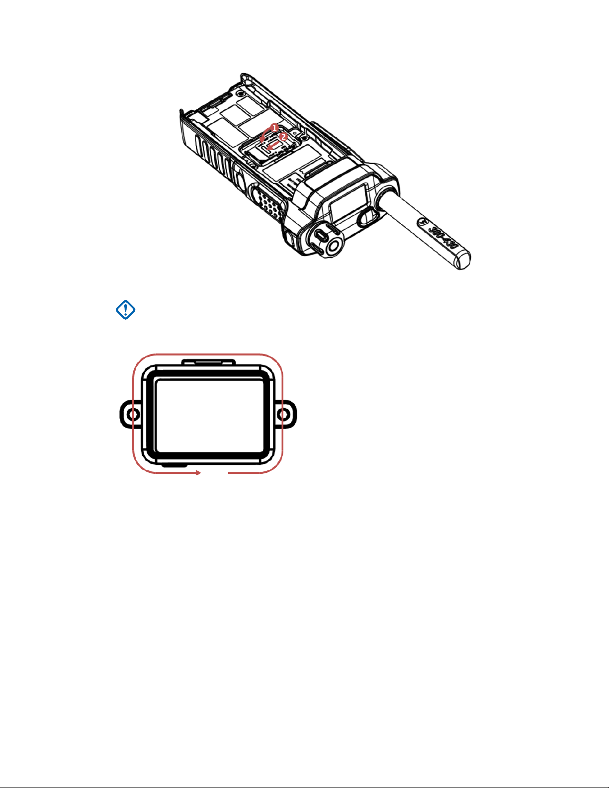
4 Slide the SIM card holder toward the dust cover side of the radio (as indicated by the UNLOCK
arrow) to unlock it and lift it up.
5 Slide the dummy SIM card in the direction shown in the following figure to remove it from the
SIM card holder.
Send Feedback 25
Page 26

MN002041A01–AA
Chapter 2: Getting Started
6 Slide the SIM card into the SIM card door. Pay attention to the correct position of the notched
corner.
7 Close the SIM card holder and slide the holder toward the PTT side of the radio (as indicated by
the LOCK arrow) to lock it.
26 Send Feedback
Page 27
MN002041A01–AA
Chapter
2: Getting Started
8 Visually inspect the SIM card door O-ring before slotting the SIM card door into the chassis.
IMPORTANT: Replace the SIM door if there is any damage/tear/delamination on the O-
ring seal.
9 Apply some grease (part number: 1110027B23) on the perimeter of the SIM card door O-ring.
10 Ensure proper positioning of the SIM card door by matching the shape of the SIM card door to
the chassis (see the below figure). Carefully insert the SIM card door into the back chassis SIM
opening, making sure that the SIM card door O-ring is not squeezed by the door (it must not be
visible once the door is installed).
Send Feedback 27
Page 28

MN002041A01–AA
Chapter 2: Getting Started
11 Apply pressure on the SIM card door and
fasten the SIM card door screws to the chassis with torque setting of 1.0±0.1 in-lbs (0.113±0.011
Nm).
IMPORTANT: Ensure that the SIM card door is firmly screwed and the
door O-ring cannot be seen.
12 Install the battery.
2.2.3
use the Torx driver with T-5IP TORX-PLUS bit to
grey SIM card
MicroSD Card
The microSD card is supported only by radios equipped with a SIM/microSD card slot. The slot is
located under the battery at the back of the radio. If the SIM/microSD card slot is not available, the
radio uses its internal flash memory to store data.
The radio supports two types of the microSD cards:
Micro Secure Digital Card (microSD card) with a capacity of 2 GB.
•
• Micro Secure Digital High Capacity Card (microSDHC card) with a capacity from 4 GB to 32 GB.
The radio supports the microSD cards that meet the following criteria:
• Capacity of 2, 4, 8 GB
• Industrial grade
• Formatted in FAT32
NO SD card can mean both:
• no physical SD card fitted
• SD card fitted is not accepted/recognized
28 Send Feedback
Page 29
NOTICE:
The radio only supports the following characters to compose file names:
1 numeric digits
2 English alphabetic characters
3 space
4 non-alphabetic characters: ! # $ % & ' ( ) - @ ^ _ ` { } ~.
Before using non-alphabetic characters from point 4, make sure your computer system supports
them.
To achieve the best radio performance, use microSD cards with the minimum write speed of at
least 6 MB/s (Class 6 or higher). Cards with the write speed lower than 6 MB/s slow down the
performance of the radio.
2.2.4
Installing the MicroSD Card
IMPORTANT: The following procedure must be performed only in non-hazardous environment.
Prerequisites:
Your radio is equipped with a SIM/microSD card slot.
Prepare T-5IP TORX – PLUS screw bit and 1.0 ±0.1 in-lbs torque screwdriver.
MN002041A01–AA
Chapter 2: Getting Started
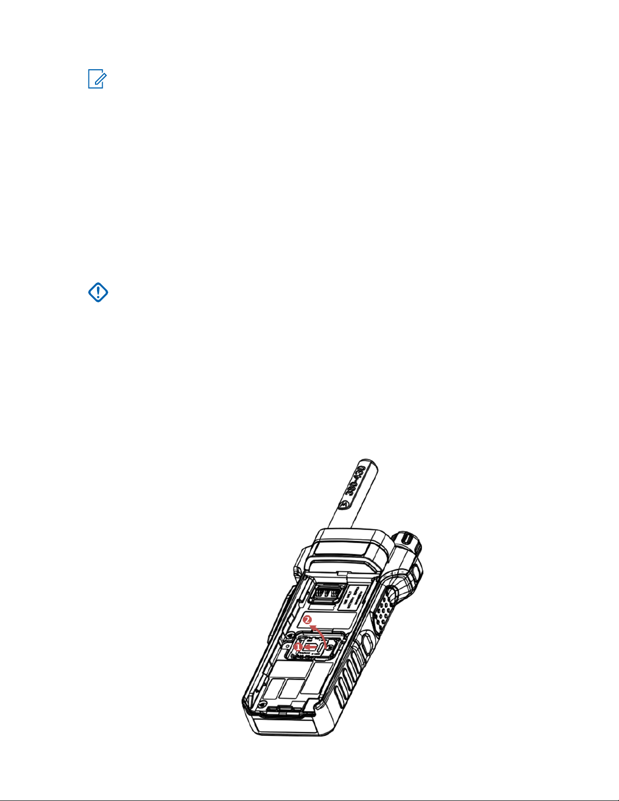
Procedure:
1 Remove the battery.
2 Remove the SIM card door (see Installing the SIM Card
3 Slide the SIM card holder toward the dust cover side of the radio (as indicated by the UNLOCK
arrow) to unlock it and lift it up.
on page 24).
Send Feedback 29
Page 30

MN002041A01–AA
Chapter 2: Getting Started
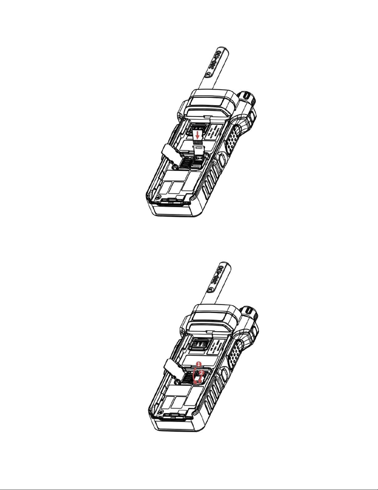
4 Slide the microSD card holder toward the top of the radio (as indicated by the UNLOCK arrow)
to unlock it and lift it up.
Figure 1:
5 Carefully insert the microSD card into the microSD card holder ensuring that the gold contact
area is facing down.
30 Send Feedback
Page 31
MN002041A01–AA
Chapter 2: Getting Started
6 Close the microSD card holder and slide the holder toward the bottom side of the radio (as
indicated by the LOCK arrow) to lock it.
Figure 2:
Send Feedback 31
Page 32

MN002041A01–AA
Chapter 2: Getting Started
7 Close the SIM card holder and slide the holder toward the PTT side of the radio (as indicated by
the LOCK arrow) to lock it.
IMPORTANT: Make sure the SIM card holder is not left empty, the holder must be
occupied by either the dummy SIM card or an actual SIM card.
8 Install the SIM card door (see Installing the SIM Card on page
9 Install the battery.
NOTICE: Due to a delicate construction of the SIM/microSD card slot, do not insert or
remove the microSD card unnecessarily, as it may damage the mechanism of the reader.
For copying files from the radio, use the USB Mass Storage Mode.
2.2.5
24).
Installing the Battery
IMPORTANT: The following procedure must be performed only in non-hazardous environment.
Procedure:
1 Remove the battery from its protective case.
2 Insert the battery from the back of the radio. Ensure it is fully seated in the radio chassis
compartment.
3 Carefully slide the battery from the bottom toward the top of the radio until it clicks into place.
NOTICE:
Your service provider can configure the radio to turn on automatically after you insert
•
the battery.
• Your radio always powers up, if you remove the battery for a period shorter than 3-5
seconds.
32 Send Feedback
Page 33

2.2.6
Removing the Battery
IMPORTANT: The following procedure must be performed only in non-hazardous environment.
Prerequisites: Turn off the radio.
Procedure:
1 Move the latch in the direction indicated by the arrow and hold it.
2 Slide the battery toward the bottom of the radio to remove it.
Chapter
MN002041A01–AA
2: Getting Started
2.2.7
Charging the Battery
You can charge a battery separately or attached to a radio.
Charging a battery attached to a radio can be done with the radio either turned on or off. The battery
charges faster when the radio is turned off.
IMPORTANT: Use only Motorola approved chargers which provide optimal performance.
other chargers invalidates the warranty, as well as may fail to fully charge, and reduces the life
of the battery.
Always charge your IMPRES battery with an IMPRES charger for optimized battery life.
IMPRES batteries charged exclusively with IMPRES chargers receive a 6-month capacity
warranty extension over the standard Motorola Premium battery warranty duration.
Prerequisites:
Do not charge the battery in a hazardous area.
IMPORTANT: Do not connect a radio without a battery to the charger.
Procedure:
1 Connect the charger to an appropriate power source (100–240 V, 12 V), according to the
specification of the charger.
2 Insert the battery or the radio with the battery attached into the appropriate socket. The LED on
the charger indicates that the charging is in progress.
Using
Send Feedback 33
Page 34

MN002041A01–AA
Chapter 2: Getting Started
NOTICE: If a multi-unit charger LED indicates an error (blinking red light) when radio is
inserted and being charged with the multi-unit charger (MUC), re-insert the radio. If the
light is still red after several reconnections to MUC, the battery may be damaged or
depleted.
Postrequisites: The battery may heat up during charging. After charging, make sure that the battery
and the radio are within the operating temperature range before using the radio.
2.2.8
Charging Indicators
When your radio is turned on while charging, it displays an icon of the battery in charging.
When the radio is turned on while charging, an appropriate Battery Charge Progress icon is displayed
in the status icon area.
When the radio is turned off while charging, a Charger Mode screen is shown on the display. The
screen contains an appropriate Battery Charge Progress icon and charging progress expressed in
percentage.
Figure 3: Charger Mode Screen
When your radio is turned off while charging, it remains turned off while the battery is being charged.
Table 3: Battery Icons
Battery Capacity
0%–5% 5%–15% 15%–25% 25%–40% 40%–60% 60%–80%
80%–
100%
Battery Charge Progress
0%–5% 5%–15% 15%–25% 25%–40% 40%–60% 60%–80%
80%–
100%
Table 4: LED Indicators
Indication Status
Solid green Battery fully charged
Table continued…
34 Send Feedback
Page 35

Indication Status
Blinking green Battery charged at 90%
Solid red Rapid charge
Blinking red Faulty or invalid battery
Blinking orange Battery is waiting to charge
NOTICE:
When you charge your radio in a multi-unit charger and the battery is at the 90–100% charge
level, the LED indicators on the radio and on the multi-unit charger differ:
LED on the radio – blinking green
•
• LED on the multi-unit charger – solid green
For more accurate representation of the charging levels refer to LED Indications on page 165.
NOTICE:
If you insert a radio with a deeply discharged battery into the multi-unit charger, the LED on the
radio may indicate a charging error (blinking red). This can be cleared by reinserting the radio.
2.2.9
Low Battery Indication
Chapter
MN002041A01–AA
2: Getting Started
The radio indicates low battery level by playing an audible alert when the battery charge falls to a
preset level. The low battery alert can be programmed by your service provider to 5, 10, or 20 per cent
of remaining capacity. The default setting is 5 per cent. The service provider also configures how
frequently the alert repeats.
Send Feedback 35
Page 36

3
6
7
8
9
5
4
3
2
1
17
18
6
19
20
21
16
14
11
12
10
13
15
MN002041A01–AA
Chapter 2: Getting Started
2.3
Controls and Indicators
Table 5: Controls and Indicators
Annotation Description
1 PHOTOSENSOR
2 ROTARY KNOB
Table continued…
36 Send Feedback
Page 37

Annotation Description
• Rotate to set the volume.
Press and rotate to select a different talkgroup.
•
• Press and hold the ROTARY KNOB to lock/unlock it. Powering the radio off and
on also unlocks a locked ROTARY KNOB.
3 Programmable SIDE buttons
The SIDE buttons support the One Touch Button feature. By default the upper
SIDE button is set to Flip Display and the lower SIDE button is set to High/Low
Audio.
NOTICE: The required time to press and hold a button to activate a
One-Touch Button feature is by default set to 0.1 second.
4 EARPIECE
5 PTT (Push-To-Talk)
•
Press and hold to talk in simplex calls, release it to listen.
6 SOFT key
Press left or right SOFT key, to select the option that appears above.
MN002041A01–AA
Chapter 2: Getting Started
7 SEND key
• Press to initiate or answer duplex calls, or send messages.
• Press in home screen to enter Recent Dialed Calls.
8 KEYPAD
Use the keypad to enter alphanumeric characters for dialing, contact entries,
and text messages.
The keys (0-9, * and #) support the One-Touch Button feature. Press and hold
a key to activate a one-touch function assigned to it.
NOTICE: The required time to press and hold a button to activate a
One-Touch Button feature is by default set to 1 second.
9 BOTTOM
MICROPHONE
Activated during Duplex low audio calls such as Private Calls.
10 ANTENNA
11 TOP LED DISPLAY Features a high resolution of 200 x 112 pixels screen with
262,144 colours
12 LED COVERAGE INDICATOR
For ultimate safety, the radio is fitted with an LED Coverage Indicator to show
when coverage is poor.
13 EMERGENCY button
Press and hold the EMERGENCY button to start Emergency Operations. By default, when your radio is off, press and hold to power on in Emergency Operations.
14 TOP MICROPHONE
15 NAMEPLATE
To use a stick-on labels or external markers to easily identify the radio.
Table continued…
Send Feedback 37
Page 38

MN002041A01–AA
Chapter
Annotation Description
16 DISPLAY
17 SIDE CONNECTOR
18 MENU key
2: Getting Started
Features a high resolution of 240 x 320 pixels and 262,144 colors. Supports
scalable fonts and high color images.
Provides connection for accessories. You can connect the following cables:
•
• Serial Data Cable Ex, PMKN4159_
• USB Data Cable Ex, PMKN4160_
• E2EE KVL Cable Ex, PMKN4161_
•
• Used to enter context-sensitive menus.
Boot Programming/USB Data Cable Ex, PMKN4158_
NOTICE: It is recommended to turn off the radio before connecting
accessories.
From the home screen, press to enter the main menu.
19 SPEAKER
20 ON/OFF/END/HOME key
• Press and hold to turn on/off your radio.
• Press to end calls.
• Press to return to the home screen.
21 NAVIGATION key
Press up, down, left or right NAVIGATION key for list scrolling, while moving
around the menu hierarchy, or for alphanumeric text editing.
From the home screen, press to activate one of the following:
• Down NAVIGATION key – enters Recent Calls menu item.
• Up NAVIGATION key – changes My Groups talkgroup folder.
• Left and right NAVIGATION key – toggles through the talkgroups.
NOTICE: A detailed list of compatible accessories is included in Accessory Leaflet. To obtain
the document, contact your service provider.
2.4
Display
This section presents the radio's default home screen elements.
38 Send Feedback
Page 39

Figure 4: Default Home Screen with Icons
Optns
262/5003
Folder 1
Test Group 1
Contcs
1
2
3
4
Table 6: Display
Annotation Description
MN002041A01–AA
Chapter 2: Getting Started
1 Status icon area
2 Text display area
3 SOFT key area
4 MENU/Context sensitive icon
The color of the SOFT key area changes according to the mode the radio is in.
Table 7: Colors of the SOFT Key Area
Color Mode or State
Light blue Normal TMO and DMO Modes
Light red Emergency Mode or Disaster Alert Call
Olive Local Site Trunking Mode
Yellow Call Out — Standby
Red Call Out — Alert
Green Call Out — Accepted
Blue Radio Messaging Service (RMS)
Grey Radio User Assignment (RUA) — Limited service
2.4.1
Configurable Idle Screen
Your service provider can configure the information that is displayed on the idle screen below the
status icon area. Depending on the radio configuration and services supported, the following
information can be displayed:
• Radio Status
• Network alias (No Service or MCC/MNC or Networks Alias)
Send Feedback 39
Page 40

MN002041A01–AA
Chapter 2: Getting Started
• Range alias
Talkgroup alias
•
• Home mode display
• Time and date
• RMS/FMS
• ISSI
• Audio profile name
• Gateway Background Mode (with one of the reasons for entering the mode):
- Configuration
- TMO Failure
- Gateway Detected
- Repeater Call
- DMO Call
- Unknown
Order and visibility of these items are also subject of the Configurable Idle Screen settings.
2.5
Status Icons
Status icons appear when your radio is engaged in certain activities or when you have activated certain
features.
Depending on your service provider settings, status icons can appear in normal or large size. By
default, they are large on the home screen and normal when browsing though the radio menu.
Table 8: Status Icons
Icon Description
Trunked Mode Operation
In Service
or
No Service
or
Signal Strength – The more bars, the stronger the signal.
or
RF Power – Indicates the High RF Power is enabled. Shows the signal strength.
or
The more bars, the stronger the signal.
Migration – Displayed when your radio is registered to the foreign network.
Broadcast Call – Displayed when the radio is in the Broadcast Call.
Scan – Indicates talkgroup scanning is activated in the radio.
Packet Data / Multi-Slot Packet Data (MSPD) – The more blue sections on the
icon, the faster the data transfer. Possible three states:
Table continued…
40 Send Feedback
Page 41
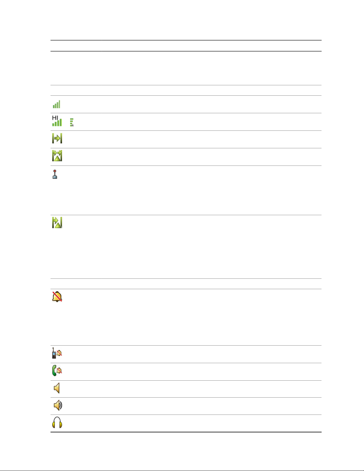
Icon Description
• Four gray sections: context activated – data idle
One blue (from the left): Packet Data active
•
• Two blue (from the left): Multi Slot Packet Data active
Direct Mode Operation
Direct Mode Call – Displayed when the radio is receiving a Direct Mode call.
The more bars, the stronger the signal.
High RF Power: receiving – Displayed when the High RF Power option is ena-
or
bled and the radio is receiving a call.
Direct Mode – Displayed when the radio is in Direct Mode (radio-to-radio communication).
Repeater Mode – Displayed when the radio is switched to work as a repeater in
Repeater Mode.
DMO Gateway Communication Mode – Indicates that gateway is selected. The
icon has the following states:
Solid – while the radio is synchronized with the gateway.
•
• Blinking – while the radio is not synchronized or during attachment.
• No icon – during a radio to radio and repeater call.
MN002041A01–AA
Chapter 2: Getting Started
General Icons
DMO Repeater Communication Mode – Displayed when the Repeater or GW +
Rep option in DMO Mode is selected. This icon has the following states:
Solid – while the radio has detected the repeater (for example when the ra-
•
dio receives a presence signal).
• Blinking – while the radio has not detected the repeater or during attachment.
• No icon – during a radio to radio and gateway call.
All Tones Off and Duplex and Simplex Ring Muted – Indicates that all alert
tones are off and both duplex an simplex ring volume is set to 0.
All Tones Off – Indicates that:
Volume is set to 0 (when Volume Adj. Mode is set to Common).
•
• Both simplex and duplex ring volume is set to 0 (when Volume Adj. Mode is
set to Individual).
Simplex Ring Muted – Indicates that simplex ring volume is set to 0 and duplex
ring volume is set to more than 0.
Duplex Ring Muted – Indicates that duplex ring volume is set to 0 and simplex
ring volume is set to more than 0.
Low Audio – Indicates that the audio mode is changed to low.
High Audio – Indicates that the audio mode is changed to high.
Earpiece Connected – Indicates that the earpiece is connected.
Table continued…
Send Feedback 41
Page 42
MN002041A01–AA
Chapter 2: Getting Started
Icon Description
Horn and Lights – Indicates that an external alarm (for example, horn and lights)
is activated.
GNSS Icon
Solid - the radio has a location fix
•
• Blinking - the radio is acquiring a location fix. This is an optional setting and
may not be enabled on your radio.
RUI Logged on – Indicates that you are logged on into the radio.
RUI Pseudo Log On – Indicates that you are in pseudo logged on state.
RUI Packet Data – Indicates Pseudo Log On state when the Packet Data feature is activated and active data session is in progress.
RUI Packet Data – Indicates Pseudo Log On state when the Packet Data feature is activated and the external device sets up data connection with the radio.
Battery Strength – Shows the charge of your battery.
Battery Charging – Indicates that the battery is charging.
Emergency – Appears while the radio is in Emergency Operation.
Disaster Alert Call – Appears while the radio is in the Disaster Alert Call.
List Scrolling – Displayed to indicate that the ROTARY KNOB is in list scrolling
mode.
New Message Has Arrived – Indicates a new message just arrived.
New Message(s) in Inbox – Indicates that you have unread messages in your
Inbox.
Unread (New) WAP Message – Indicates that new page was loaded to the
browser.
Man Down Active – Indicates that the Man Down feature is active.
Man Down Alert – Displayed when the Man Down feature is active. This icon
has two states:
•
Blinking – pre-Alert; the radio signalizes Man Down conditions. To exit the
pre-Alert state, change the conditions or press the PTT.
• Solid – the radio entered the Alert mode.
Man Down Failure – Indicates the Man Down device failed.
Call-Out – Indicates Call-Out alert.
Call-Out Alert Arrived – Indicates a receipt of a new Call-Out message.
Table continued…
42 Send Feedback
Page 43
Icon Description
Call-Out Alert Unread – Indicates unread alert in the CO Box.
End-to-End Encryption (E2EE)
Solid, when the E2EE is enabled
for the selected talkgroup,
•
• for the highlighted private number,
• for the manually entered private number,
• when transmitting voice in Group Calls,
• when transmitting voice in Simplex Private Calls.
Blinking, when the End-to-End Encryption is enabled
• when receiving voice in Group Calls,
• when receiving voice in Simplex Private Calls,
• during encrypted Duplex Private Calls.
Encryption Off
Blinking, indicates that the SIM Card End-to-End Encryption is disabled in
DMO and TMO Modes.
MN002041A01–AA
Chapter 2: Getting Started
or
SIM End-to-End Encryption (E2EE)
Solid, indicates that the SIM Card End-to-End Encryption is enabled in TMO
Mode.
SIM End-to-End Encryption (E2EE)
Solid, indicates that the SIM Card End-to-End Encryption is enabled in DMO
Mode. Numbers 1 and 2 point to the type of DMO Encryption keys that has
been selected.
SDS End-to-End Encryption
Solid, when the E2E status of an SDS message, or the E2E status of a mes-
sage recipient address.
In High Security mode, when your radio processes only the encrypted infor-
mation, this icon is always visible in when you are in the messages menu
(for example, Inbox).
Unread (New) WAP Message – Indicates that you have not entered WAP Box
since last WAP message was received (Blinks when the priority is high).
WAP Message Icon – Displayed next to the priority in the message list view.
WAP Message Time – Displayed next to the create date in the message list
view.
WAP Message Expiration – Displayed next to the expiry date in the message
list view.
WAP Message Title Icon – Displayed next to the title along with the text in the
message list view.
Keys Locked – Indicates that keys are locked.
Table continued…
Send Feedback 43
Page 44

MN002041A01–AA
Chapter 2: Getting Started
Icon Description
Non Secured Call – Air Encryption Unavailable
Blinking, indicates that Air Encryption is not available when the radio:
Is in the Local Site Trunking Mode.
•
• Attempts to connect to a gateway.
Not Secured Call – Air Encryption Unavailable
Alternately blinking, indicates that Air Encryption is not available when the
radio:
Is in TMO Mode.
•
• Communicates through a gateway.
Not Secured Call – Air Encryption Unavailable
Blinking, indicates that Air Encryption is not available in DMO Mode. The
icon appears after the
Non-formatted SD Card
Solid – The microSD card is:
•
- Not formatted at all,
- Formatted incorrectly, or
- Damaged.
• Blinking – The microSD card is being formatted.
PTT button is pressed.
USB Connected – Indicates that the radio is connected to the computer via the
USB cable. Visible only in the Mass Storage mode.
Bluetooth Connected. Bluetooth is enabled and at least one device is connected.
Bluetooth Disconnected
Solid indicates that Bluetooth is enabled, but no device is connected.
Blinking indicates one of the following:
Bluetooth is enabled and the radio is in the Discoverable Mode.
•
• Bluetooth is enabled and a connection with a remote device is being established.
An outgoing OPP transfer (upload).
An incoming OPP transfer (download).
Remote Control
Indicates that the radio is being remotely controlled and some commands
are being executed in the background. For example, when the radio is controlled via special SDS messages or triggered to send a GNSS location report.
The icon is not visible in the Extra Zoom Mode.
44 Send Feedback
Page 45

MN002041A01–AA
Chapter
2.6
2: Getting Started
Powering On the Radio
Procedure:
Press and hold
Your radio performs a self-check and registration routine.
After successful registration, your radio is in service.
NOTICE: Your radio powers on without visible and audible notification if Covert Mode is
activated.
2.7
ON button.
PIN Code Authentication
If pre-set by your service provider, the radio has active PIN Code Authentication, which helps you
increase security and protect your radio against unauthorized use. The PIN code is read from the SIM
card or radio programming and cannot be changed or disabled. If you are unable to unlock the radio,
you cannot send or receive any call, nor adjust the volume level with the
You are asked to enter the PIN code each time you turn on the radio.
ROTARY KNOB.
2.7.1
Unblocking Your Radio
Prerequisites: You blocked your radio by entering incorrect PIN code for three times (by default).
Procedure:
1 Radio displays Unit BlockedEnter PUK.
2 Enter 8–digit PUK (Personal Unblocking Key) number.
NOTICE: The PUK is an eight-digit master code provided by your service provider.
3 Enter the new PIN code twice.
2.8
Unlocking Your Radio
Your radio may be locked at power up. To unlock it after powering on, enter the code at the prompt.
Your radio enters the default home display.
NOTICE: The unlock code is originally set to 0000. Your service provider may change this
number before you receive your radio.
2.9
Locking/Unlocking the Keys/Buttons
Press MENU key and *Left NAVIGATION key.
NOTICE: The EMERGENCY
Send Feedback 45
button is not locked. Entering Emergency Mode unlocks all keys.
Page 46

MN002041A01–AA
Chapter 2: Getting Started
2.10
Holding Your Radio
The radio has two microphones: a top microphone for simplex dispatcher/private calls and a bottom
microphone for duplex telephone-like calls.
Also, the radio is equipped with an internal speaker for high audio (located at the middle of the unit)
and an internal earpiece for low audio (located at the top of the unit).The audio can be routed either to
the speaker or the earpiece using the Audio Toggle menu (
or the assigned One-Touch Button.
NOTICE: For best performance speak directly into the top microphone.
Simplex Calls
When using high audio, hold the radio a vertical position with its top microphone 5 centimeters to 10
centimeters away from your mouth. Speak into the top microphone. Listen through the internal
speaker. Keep the antenna at least 2.5 centimeters from your head and body.
MENU → Setup → Audio → Audio Toggle)
Duplex Calls
When using low audio, hold your radio as you would a telephone. Speak into the bottom microphone.
Listen via the earpiece. Keep the antenna at least 2.5 centimeters from your head and body.
Lapel/Shoulder Use
For Group and Private Calls turn your head towards your shoulder/lapel, and speak directly into the top
microphone. Listen through the internal speaker.
Speakerphone Use
Place your radio 30 centimeters to 60 centimeters away from you. In a noisy environment, move the
radio closer to you for better transmission.
2.11
Entering TMO / DMO Mode
Procedure:
1 From the home screen, press Optns.
2 Select Trunked Mode / Direct Mode.
46 Send Feedback
Page 47

MN002041A01–AA
Chapter 2: Getting Started
2.12
Transmit Inhibit Mode
The Transmit Inhibit Mode is a mode in which the radio sends no radio transmissions. It is
recommended to activate the mode in RF sensitive areas, for example hospitals, airplanes, where
safety can be jeopardized due to transmission radiation.
To activate, select MENU → Networks → TXI Mode → Activate.
In this mode, the radio does not transmit under any circumstances except for the Emergency Calls. All
the functions and keys which cause transmission, for example registration to the network, changing
talkgroup or folder, sending SDS messages, or pressing the
trial causes the radio to display Not Allowed In TXI Mode notification and to play a tone.
Your radio can still receive:
• Group calls.
• Messages — stored in the Inbox.
• Private call attempts — stored in the Missed Calls list, without the option to respond.
When no danger to safety exists anymore (for example, you leave the RF sensitive area), you can
deactivate the Transmit Inhibit Mode and the radio returns to standard operation.
You can deactivate the mode by selecting MENU → Networks → TXI Mode → Deactivate, pressing
One-Touch button, or implicitly when initiating an Emergency Call.
PTT button are disabled. Any transmission
NOTICE: RF Transmissions from the radio are prevented under the following conditions:
TXI Mode is activated.
•
• Battery is removed.
• The radio is turned off.
On entering or exiting the transmit inhibit mode, when the radio is camped on a cell, it sends a
specially designated SDS status message. This SDS message indicates to the SwMI that the radio is
entering or exiting transmit inhibit mode.
Mobility procedures that do not require the radio to send an uplink transmission are performed except
for cell reselection.
In transmit inhibit mode the radio joins group calls for any group that the radio is monitoring, but the
transmitting on that call is still prohibited.
The radio also displays any incoming SDS messages to the user. The missed call feature is active in
the transmit inhibit mode and allows checking what calls were missed. However, the radio attempts to
prevent call setup retransmission from being recorded as separate calls.
If you initiate an emergency call, the radio immediately leaves transmit inhibit mode and attempts to
start the emergency call if the radio is in service.
If the radio is turned off in the transmit inhibit mode, on turning on the radio asks whether to exit the
transmit inhibit mode. If you choose No, the radio turns off.
2.13
Selecting Talkgroups
From the home screen, use one of the following methods:
• Press left or right NAVIGATION key. Press Select to confirm.
• Select Optns → TG by abc. Enter a talkgroup name and select the talkgroup name from the list.
• Select Optns → TG by Folder. Select a folder (for example, Favorite) and then a talkgroup name.
Send Feedback 47
Page 48

MN002041A01–AA
Chapter
2: Getting Started
• Press ROTARY
confirm.
NOTICE: If the
the scrolling mode.
NOTICE: Your radio can have an access up to three levels of the folder structure.
2.14
KNOB and rotate it until the required talkgroup name is displayed. Press Select to
ROTARY KNOB mode is set to Scroll, then you do not need to press it to enter
Talkgroup Icon Selection
Table 9: Talkgroup Icon
Icon Description
Displayed when the talkgroup is from a different network than the one currently
selected.
2.15
Using Timed Talkgroup Change
This feature allows you to switch a selected talkgroup between the currently selected talkgroup and a
predefined talkgroup (TMO or DMO), making the predefined talkgroup the selected talk group for a
predefined time by using
previously selected talkgroup.
a One-Touch button. After the timer expires, your radio returns to the
Prerequisites: Timed Talkgroup Change is assigned to a One-Touch button.
Procedure:
1 Press and hold and hold the One-Touch button.
2 Your radio switches the selected talkgroup to the predefined talkgroup for a predefined amount
of time.
During the predefined time the radio initiates or joins group communication (SDS, status SDS, or
call) on the predefined talkgroup as the selected talkgroup.
Your service provider can assign a function to the second press of the One-Touch button to:
• Return to previously selected talkgroup
• Restart the predefined time
• No action
3 When the timer expires (potentially after being restarted a number of times) the radio switches to
the previously selected talkgroup.
2.16
Broadcast Call
The Broadcast Group Call (also called Site Wide Call) is a high-priority group call from the console
operator (or dispatcher) to all users located at one or more sites. The radios are configured to monitor
a Broadcast Call, but you cannot talk back. The call can be received as a normal Broadcast Call or an
Emergency Broadcast Call. The Broadcast Call preempts an ongoing Group Call that has the same or
lower call priority.
48 Send Feedback
Page 49

MN002041A01–AA
Chapter
2.17
2: Getting Started
Private Call
The Private Call, also called point-to-point, or individual call, enables calling between two individuals.
No other radio can hear the conversation. This call type can be carried out in two ways:
Duplex call (if the system allows), in TMO Mode. Both parties can speak at the same time. Start the
•
conversation using the SEND key.
• Simplex call, in TMO or DMO Mode. Only one party can speak at a time. Start the conversation
using the PTT button.
When a DMO Private Call takes place, radios not involved in this call receive the channel busy
indication. The radios are identified using its radio numbers.
2.17.1
Making Private Calls
Procedure:
1 From the home screen, enter a number.
2 If Private is not the first type of call presented, press Ctype repeatedly to select it.
3 When you are in the following mode:
a TMO — For simplex calls, press and release the PTT button. You hear a ringing tone.
Otherwise, press and hold the PTT button. Wait for the talk permit tone before talking, and
release the PTT button to listen. For duplex calls, press and release the SEND key. You hear
a ringing tone.
b DMO — Only simplex calls are available. Press and hold the PTT button. Wait for the talk
permit tone before talking, and release the PTT button to listen.
4 To end the call, press the END key.
2.18
Ambience Listening (AL) Call
This feature allows a dispatcher to make a special call that allows listening to the conversations and
background noises within the range of a particular radio’s microphone. The call is set up without any
indication to the affected radio, and any lower priority ongoing voice call or packet data transfer may be
preempted.
After accepting the call, the radio transmits in a simplex call without any action from or indication to the
user. The Ambience Listening Call automatically ends when you initiate any voice call, switch to
Emergency or TXI Mode, or send Emergency Alarm.
Send Feedback 49
Page 50

MN002041A01–AA
Chapter 2: Getting Started
2.19
One-Touch Button Feature
The One-Touch Button feature allows for quick activation of functions by pressing and holding keys or
buttons assigned to those functions.
NOTICE: All the features can be assigned on the option buttons for RSM accessories.
Table 10: One-Touch Button Features
Feature Description
BSI Encryption Enabled/Disabled Toggles BSI encryption feature.
Backlight Adjustment Toggles the backlight on or off.
Bluetooth Discoverable Mode Turns on/off the Discoverable Mode.
Bluetooth Smart Proximity Pairing Turns on/off Proximity Pairing
Change Audio Profile Change to the specific audio profile.
Change Font Size Scrolls through font sizes.
Change Talkgroup Changes the talkgroup to the programmed one by your
service provider.
Change Talkgroup to the Previously
Selected Talkgroup
Connect/Disconnect RSM Earpiece Activates or deactivates the RSM earpiece.
Covert Mode Turns on/off the Covert Mode.
Direct Private Number Dialing Dials a predefined private number.
Disconnect All Connected Bluetooth
Devices
Display Bluetooth GATT Sensors
Battery Levels
Display GATT Service Data GATT-based sensor data is displayed on the radio.
Display OPTA Displays the Operative Tactical Address (OPTA).
Display Time Displays universal time on the home screen.
Sending of Double Push PTT (DPTT)
Enable/Disable Howling Suppression Turns on/off Howling Suppression.
Flip Display Rotates the display by 180 degrees.This is the default
Changes the selected talkgroup of the radio to the talkgroup (DMO or TMO) that was selected previously.
Disconnects all Bluetooth devices connected to the radio.
Battery levels of all paired Bluetooth GATT-based sensor
devices are displayed on the radio.
Sends the D- PTT tone to the currently used talkgroup.
function for the upper
SIDE button.
LIP Report Sends a message with the radio’s location to a dedicated
address.
Hi/Low Audio Toggles high/low audio. This is the default function for the
lower SIDE button.
Initiate Call-Out Fallback Alert Sends Call-Out Fallback Alert.
Man Down On/Off Turns on/off the Man Down feature.
Table continued…
50 Send Feedback
Page 51

MN002041A01–AA
Chapter 2: Getting Started
Feature Description
PABX Call Initiates a PABX call to a predefined entry in the contact
list.
Phone Call Initiates a phone call to a predefined entry in the contact
list.
Private Call Initiates a private call (simplex or duplex) to a predefined
entry in the contact list or to the last group call originator.
RMS Mode (applicable only for * and#)Toggles on/off RMS feature.
RMS MMI Menu Opens the RMS menu. The RMS Mode does not need to
be activated.
Rotary Switches Lock/Unlock Locks/unlocks the Rotary Switches.
LOG ON <-> LOG OFF RUI Asks for the credential or logs off the radio.
Add Bluetooth Device Activates scanning for Bluetooth devices.
Bluetooth Indoor Location Activates Bluetooth Indoor Location
Screen Saver Activation Turns on/off the Screen Saver feature.
Scroll Audio Profiles Scrolls through all available audio profiles.
Sending Predefined Message Sends a predefined message to a dedicated address.
Sending Status Sends a dedicated status message to a dedicated ad-
dress.
Sending User Defined Message Sends a user defined message to a dedicated address.
Speaker Enable/Disable Per Call Enables the loudspeaker for a duration of the ongoing call.
Timed TG Change Makes a predefined talkgroup the selected talk group for a
specified amount of time. While using the predefined talkgroup, the second press of the One-Touch Button results
in: returning to the previously selected talkgroup, restarting
the predefined time, or no action (depending on configuration). After the timer expires, the radio returns to the previously selected talkgroup.
TMO / DMO Switch Toggles between TMO and DMO modes.
TMO Talkgroup Scan Turns on/off the Talkgroup Scan feature in TMO Mode.
Toggle Backlight Intensity Regulates the backlight intensity.
Toggle RF Power Class Toggles the RF Power Class between High and Normal.
Toggle the SIM Card End-to-End En-
Toggles the SIM Card End-to-End Encryption.
cryption
Transmit Inhibit Mode (TXI) Turns on/off the Transmit Inhibit Mode.
Turn On/Off Bluetooth Turns on/off Bluetooth.
Turn On/Off Repeater Mode Turns on/off the Repeater Mode.
Volume Down
• Press to decrease the volume by one level.
Press and hold to continuously decrease the volume to
•
its minimum level.
Table continued…
Send Feedback 51
Page 52

MN002041A01–AA
Chapter
Feature Description
2: Getting Started
Volume Up
Unassigned No feature assigned to this button.
Your service provider can assign one-touch functions only to the side buttons and keypad keys.
NOTICE: If the One-Touch Button feature is enabled, the One-Touch Dial is disabled. If no
feature is assigned to a button, your radio displays an Unassigned Button message.
2.20
• Press to increase the volume by one level.
Press and hold to continuously increase the volume to
•
its maximum level.
Terminal Temporary Disable/Enable
Your radio is provided with a feature that allows your service provider to disable it temporarily in case it
is stolen. When your radio is disabled or is powered up in disabled state, it looks and acts like it is
turned off.
If your radio is found, your service provider can enable it again over the air. After your radio is enabled,
you may resume normal operation.
2.21
Terminal Permanent Disable
NOTICE: This is a selling feature.
Your radio is provided with a feature that allows your service provider to disable it permanently in case
it is stolen or lost. When your radio is disabled permanently, it becomes inoperable
on the microSD card or in the internal radio memory is removed. After a Permanent Disable your
service provider cannot enable your radio. It is recommended to Permanent Disable your radio only
when you do not expect to recover it. If it is recovered then a Permanent Disable radio can be
reactivated by returning it to Motorola.
2.22
and all data stored
High/Low Audio Toggle
The user is able to switch from the external earpiece to the main speaker using One-Touch
buttonSPEAKER CONTROL key and is not required to disconnect the external earpiece or PHF.
The states of the routed audio are:
• Speaker HIGH — indicates that audio is routed to the main speaker.
• Speaker LOW — indicates that audio is routed to the earpiece or PHF earpiece, and not to the
main speaker.
2.22.1
Using High Audio
When and where to use: Use it when placing and receiving a Group, Phone and Private calls.
Procedure:
1 Hold your radio in a vertical position with its top microphone 5–10 centimeters away from your
mouth.
52 Send Feedback
Page 53

MN002041A01–AA
Chapter 2: Getting Started
2 Speak into the top microphone and listen through the internal speaker.
Keep the antenna at least 2,5 centimeters from your head and body.
2.22.2
Using Low Audio
When and where to use: Use it when placing and receiving a Phone, PABX, and Duplex Private calls.
Procedure:
1 Hold your radio as you would a telephone.
2 Speak into the bottom microphone and listen through the earpiece.
Keep the antenna at least 2,5 centimeters from your head and body.
2.23
During the Call
During the call, label of the right
is:
Table 11: During the Call
Soft Key Label Audio Setting
Spkr Audio goes to the main speaker (Speaker HIGH is displayed)
Erpce Audio goes to the earpiece (Speaker LOW is displayed)
PHF Audio goes to the Personal Hands Free (Speaker LOW
2.24
SOFT key indicates the next possible change. Accessory default setup
is displayed)
Writing Text
Every time that you see text entry screen, refer to this section.
To enter text, use the ROTARY KNOB or the up/down NAVIGATION key.
To change the text entry mode, press and hold the right
ROTARY KNOB.
2.24.1
Selecting Text Entry Modes
Prerequisites: Your radio displays the text entry screen.
NAVIGATION key or press and hold the
Procedure:
1 Press MENU → Entry Mode.
2 Select one of the following:
• Primary — for entering alphanumeric characters.
• Numeric — for entering numbers only.
• Symbol — for entering symbols only.
• Secondary — for entering alphanumeric characters (this mode is optional and you have to
add it to the list). It is convenient when you use one language, and sometimes wish to switch
to another one.
Send Feedback 53
Page 54

MN002041A01–AA
Chapter 2: Getting Started
NOTICE: In the text entry screen, you can also press # key repeatedly to toggle through
the entry modes.
2.24.2
Selecting Text Entry Methods and Languages
Prerequisites: Your radio displays the text entry screen.
Procedure:
1 Press MENU
2 Select one of the following:
• TAP — Enter letters, numbers, and symbols by pressing an alphanumeric key one or more
times.
• iTAP — Let the radio predict each word as you press an alphanumeric key.
2.24.3
→ Entry Setup.
NOTICE: You can use these methods in the languages programmed in the radio.
Text Entry Icons
In the text entry screen, icons tell you which text entry mode and method you are using. A character
counter displayed on the text entry icon, indicates the amount of characters that can be entered.
Press the #
Press and hold right NAVIGATION key or press and hold ROTARY KNOBto toggle through the text entry
modes.
Table 12: Text Entry Screen Icons
Primary Icon Secondary Icons Description
key to toggle through the text entry modes.
TAP — no capitals
TAP — capitalise first letter
only
TAP — all capitals
iTAP — no capitals
iTap — capitalise first letter
only
iTap — all capitals
Numeric Icon Description
Enter numbers.
Symbolic Icon Description
Table continued…
54 Send Feedback
Page 55

Enter punctuation and symbols.
Table 13: Text Entry Screen Icons
Icons Description
A-Z – all capitals
a-z – no capitals
Enter numbers and symbols: 0-9 # § ¡ ¿ ^ ~ \ } { ] [ ¤ ¥ $ £ € > < = * × % & + ; _ : / ) ( - ” ’
@ ! ? , .
2.24.4
Keys Usage
List of keys and characters in Alphanumeric Mode (TAP/iTAP).
Table 14: Keys Usage
MN002041A01–AA
Chapter 2: Getting Started
Key Alphanumeric Mode (TAP/iTAP) Symbol Mode
0 to 9 keys Numeric Mode:
•
Press to enter digit at insertion point.
• Press and hold any numeric key to enter
TAP alphanumeric mode.
• To exit TAP alphanumeric mode, press
and hold any numeric key.
0 key Press to cycle through single shift, caps lock,
+ - × * / \ [ ] = < > § #
and lower case.
1 key . , ? ! 0 1 @ ’ ” - ( ) / : _ ; + & % × * = < > € £ $ ¥ ¤ [ ] { } \ ~ ^ ¿ ¡ § #
2 key A B C 2
@ _ \
a b c 2
3 key D E F 3
/ , ;
d e f 3
4 key G H I 4
” & ’
g h i 4
5 key J K L 5
( ) [ ] { }
j k l 5
6 key M N O 6
¿ ¡ ~
m n o 6
7 key P Q R S 7
= < >
p q r s 7
Table continued…
Send Feedback 55
Page 56

MN002041A01–AA
Chapter
Key Alphanumeric Mode (TAP/iTAP) Symbol Mode
2: Getting Started
8 key T U V 8
t u v 8
9 key W X Y Z 9
w x y z 9
Table 15: Other Keys
Key Description
Any numeric key
* key
# key
• In TAP press any key to reject word completion and continue with text
entry A new completion will be displayed, if available, after the time-out
for TAP expires.
Press and hold to enter Numeric mode from TAP or iTAP alphanumer-
•
ic.
• Press to insert a space.
• In TAP press to dismiss a word completion and insert a space.
• Enter a newly created word into the user dictionary.
• Press and hold to enter a carriage return.
• Press once to cycle through all entry modes (Symbol, Numeric, Pri-
mary, and Secondary (if configured).
• Press and hold to return to the default entry mode.
€ £ $ ¥ ¤
# % *
Select Press to select the highlighted choice and place it in the main text area.
Delete
Up NAVIGATION key
Down NAVIGATION key
Left NAVIGATION key
Right NAVIGATION key
MENU If a context-sensitive menu is active, opens the Context Sensitive Menu.
2.24.5
• Press once to delete the last entered character.
• Press and hold to clear the entire main text area.
• In TAP press to reject word completion and scroll up.
• In TAP press to change previously entered small letter to capital.
• In TAP press to reject word completion and scroll within the text area.
• In TAP press to change previously entered capital letter to small.
• Press to navigate to the left. Press and hold to repeat.
• In TAP, if a word completion is available, press to reject the completion.
• Press to navigate to the right. Press and hold to repeat.
• In TAP if a word completion is available, press to accept the word.
Writing in iTAP Alphanumeric
Prerequisites: Your radio displays the text entry screen.
56 Send Feedback
Page 57

MN002041A01–AA
Chapter
When and where to use: It allows you to write quicker. For example, try to write David 232!
Procedure:
1 Press MENU
2 Select iTAPEnglish and press Back.
3 Press MENU → Entry Mode.
4 Select Primary.
5 Press 3 key.
The alternative row opens and shows D E F 3.
6 Continue entering the letters by pressing one key for each letter. Press 2, 8, 4, and 3 keys.
The alternative row highlights David.
7 Press * key.
8 Press 2 key and scroll the alternative row by pressing right
It automatically changes the entry mode to Numeric.
→ Entry Setup → Prim..
NOTICE: Automatic shift to upper case is used at the beginning of a message, after
punctuation followed by space, or for the first letter of a word created as a new contact
entry.
NAVIGATION key to reach 2.
2: Getting Started
9 Press 3 and 2 keys.
10 Press and hold 1 key until 0 at the end changes to ..
The alternative row highlights 232..
11 Scroll the alternative row by pressing the right NAVIGATION key to reach the required symbol.
12 Press Select.
You have entered David 232!.
2.24.6
Writing in TAP Alphanumeric
Prerequisites: Your radio displays the text entry screen.
Procedure:
1 Press MENU → Entry Setup → Seco..
2 Select TAPEnglish and press Back.
3 Press MENU → Entry Mode.
4 Select Secondary.
5 Press the key labeled with the desired character, once for the first character, twice for the
second, and so on.
Example: To enter letter s, press 7 key four times. To enter number 7, press the 7 key five
times. If you do not press a key for a few seconds, the character is accepted, and the cursor
moves to the next position.
Send Feedback 57
Page 58

MN002041A01–AA
Chapter 2: Getting Started
2.24.7
Word Locking
Prerequisites: Your radio displays the text entry screen.
When and where to use: To add the words that are not in the dictionary.
Procedure:
1 Press MENU → Entry Setup.
2 Select iTAPEnglish.
3 Try to enter the word. Scroll the alternate line for a word option. Each option is successively
highlighted and partially locked.
4 Enter the second part of the word. The first part remains unchanged (locked). The newly entered
letters are highlighted and then locked while you scroll to the next word option.
5 Press * key. The word is placed in the text area with a space and automatically added to the
dictionary.
2.24.8
Adding Words to the Dictionary
Each language comes with its own dictionary. You can create words (including alphanumeric
abbreviations). Once you enter a word followed by space, it is automatically stored in the dictionary
and appears as a choice whenever you press the same key combination in the future.
2.25
Home Display Text Message
Your radio is provided with a feature that allows your service provider to send special text messages to
the display. The message stays on the home screen until a new message is received. Power cycle
your radio to replace the Home Display message to the predefined one.
58 Send Feedback
Page 59
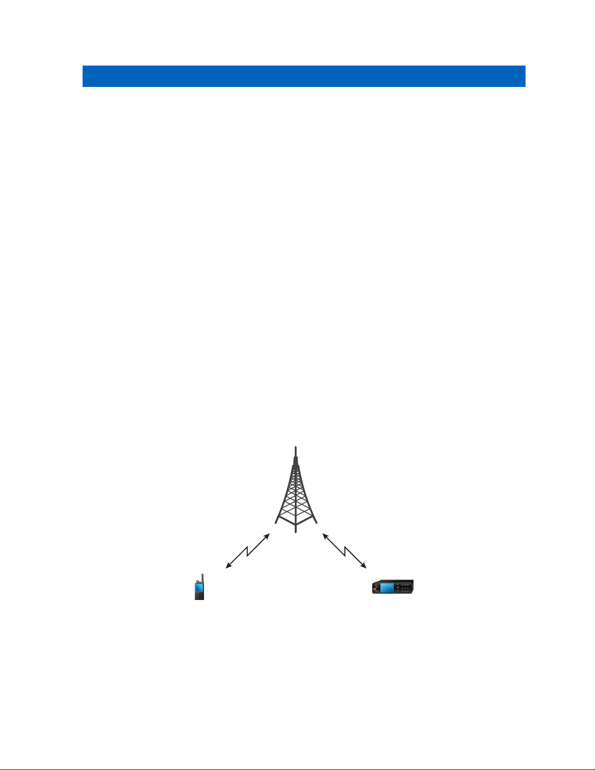
Chapter 3
Modes
This chapter contains information on available modes that the radio can operate in.
3.1
Using Networks
Procedure:
1 From the home screen, press the MENU key.
2 Select Networks.
3 Select one of the following:
• Trunked Mode
• Direct Mode
• TXI Mode
Your radio switches to the selected mode.
MN002041A01–AA
Modes
3.2
Trunked Mode Operation
Trunked Mode Operation requires the switching and management infrastructure. This operation mode
enables various voice and data communication types (for example, group calls
messages) and access to the infrastructure-related features (for example, packet data).
Figure 5: Trunked Mode Operation
, short data service
3.2.1
Entering TMO Mode
Procedure:
1 From the home screen, press Optns.
Send Feedback 59
Page 60

MN002041A01–AA
Chapter
3.2.2
3: Modes
2 Select Trunked Mode.
Making Group Calls in TMO
The Group Call is received by all members of the selected group who have their units turned on and
are connected through the network.
Procedure:
1 Press and hold the PTT button.
2 Wait for the Talk Permit tone (if configured) and then speak into the microphone. Release the
button to listen.
PTT
NOTICE: To cancel making a group call, do one the following actions before the talk
permit is granted (depending on your service provider’s settings):
Release the PTT button.
•
• Press the END key (default).
When the call is canceled, your radio displays Call Cancelled message (if configured by
your service provider).
3.2.3
Receiving Group Calls in Idle
Procedure:
1 The radio receives a Group Call.
NOTICE: The incoming Group Call is signalled by a Receiving Group Call tone.
2 To respond, press and hold the
3.2.4
PTT button.
Receiving Group Calls during Ongoing Group Calls
While in active Group Call, your radio receives a Group Call with a higher priority.
One of the following occurs:
• Your radio is forced to end the current group call and automatically join the incoming one.
• Your radio displays incoming group call screen with options:
- Join — ends current Group Call and starts the incoming one.
- End — cancels the incoming Group Call.
3.2.5
Dynamic Group Number Assignment (DGNA)
DGNA allows the network operator to dynamically manage talkgroups on your radio over the air
interface. Using DGNA, the network operator can:
• Add talkgroups.
• Attach or select newly added talkgroups.
• Delete talkgroups.
• Modify parameters of existing talkgroups.
60 Send Feedback
Page 61

MN002041A01–AA
Chapter 3: Modes
All the above operations are performed by transmitting data to your radio.
3.2.6
DGNA Reception
When a DGNA message is received, your radio plays a tone and displays a message Talkgroup list
updated. If enabled by your service provider, your radio displays all added and deleted talkgroup list.
When your service provider deletes (de-assigns) the currently selected talkgroup, depending on the
settings, the radio can perform one of the following actions:
Enter the “No Group” state – the radio does not attach to any talkgroup automatically.
•
• Attach to the last selected TMO talkgroup. If the last selected TMO talkgroup is not available (it was
deleted), the radio enters the “No Group” state.
• Attach to a default talkgroup configured by your service provider. If the default talkgroup is not
available (it was deleted), the radio enters the “No Group” state.
At each talkgroup change, an appropriate notification is shown on the display.
If the DGNA message is received to delete all talkgroups, your radio displays All Talkgroups Deleted.
To exit the DGNA display, you can use the BackSOFT key or the END key.
3.2.7
DGNA Auto Select Group
If the DGNA Auto Select is configured, whenever your radio receives a DGNA, it switches to the added
talkgroup.
3.2.8
DGNA Auto Reselect Group
If the DGNA Auto Reselect is configured, whenever a talkgroup assigned by the network operator via
DGNA is deassigned without the user action, the radio returns to the previously selected group.
3.2.9
Viewing DGNA Talkgroups
Prerequisites: Your radio receives the DGNA message.
Procedure:
1 To view the added talkgroups details press View.
2 Scroll through the list to select required talkgroup.
3 To select the DGNA group, press Attach.
3.2.10
Broadcast Calls Initiated by Users
This feature allows you to make a Broadcast Call from the radio that is initiated on the predefined
talkgroup. Your service provider predefines the alias and the priority of the Broadcast Call.
NOTICE: If the type of the encryption is defined by the SIM Card, the Broadcast Call is always
clear. Otherwise if the radio uses other encryption service the type of the encryption used for
that Call is up to the encryption settings of that service.
NOTICE: This feature is not supported on the Dimetra infrastructure.
Send Feedback 61
Page 62

MN002041A01–AA
Chapter 3: Modes
3.2.11
Initializing Broadcast Calls
Procedure:
1 From the home screen, press the MENU key.
2 Select Services → Broadcast.
Your radio displays the predefined alias and the Broadcast Call icon.
3 To start the call press the PTT
3.2.12
button.
Phone and PABX Calls
The Phone Call allows you to call a landline telephone number or a cellular mobile phone number. The
Private Automatic Branch Exchange (PABX) Call allows you to call local (office) extension numbers.
3.2.13
Assistance Call
This feature allows you make a private call to ask for assistance during normal and non-critical
situations.
NOTICE: Your service provider can configure the number, priority, and the type of the call
(simplex or duplex).
You can start an Assistance Call in one of the following way:
•
Dial a predefined number and press SEND key.
• Menu → Services → Assistance Call
3.2.14
Call Modification
Call Modification is a feature that allows your service provider to modify the call in order to optimize it
and adjust to a current situation.
Modification can cover:
• Call priority – modified during call setup.
• Call type – modified during call setup.
• Call encryption – modified during an ongoing call (but not in the transmission phase).
When the call is modified, your radio displays Call Modified message.
When a recently modified call requires the PTT button to transmit, your radio displays Call
ModifiedUse PTT.
All modifications are made by your service provider and the radio only follows them. You have no
influence on ongoing call modifications.
When call priority is changed to emergency:
• The display indicates that an Emergency Group Call has been received.
• The radio plays a special audio alert.
NOTICE: If a Group Call is modified into an Emergency Group Call, no emergency related
features are triggered.
62 Send Feedback
Page 63

MN002041A01–AA
Chapter 3: Modes
If call modification requested by your service provider cannot be followed by the radio (due to its
settings), the radio rejects it and displays Service Not Available message.
3.3
Local Site Trunking
This mode is also called as Fallback Mode and it allows more than one radio from the same site to
communicate when the link between the site and the network central controller fails. Entering and
exiting Local Site Trunking (that is, returning to System Wide Services) is done automatically. In this
mode some services are unavailable.
NOTICE: Your service provider can disable this mode.
3.3.1
Entering Local Site Trunking
When your radio receives a Local Site Trunking indication from the system, the following occurs:
•
Your radio plays an Entering Local Site Trunking tone.
• Display shows the Local Area Service message.
• Display icons and soft keys turn olive.
NOTICE: Noticeable only on the color display.
• Any call in progress is dropped upon entering Local Site Trunking Mode.
If configured by your service provider, this message/alert is periodically repeated to remind you that
your radio is still operating in Local Site Trunking Mode. The following features are available:
•
Registration
• Attachment
• Group Call
• Emergency Call
• Emergency Alarm
NOTICE: Your service provider can turn on/off all the visual and audio indications, when you
enter Local Site Trunking Mode.
3.3.2
Exiting Local Site Trunking
When the link with the central network controller is reestablished, your radio exits Local Site Trunking,
and the following occurs:
•
Your radio plays an Exiting Local Site Trunking tone.
• Any call in progress during Local Site Trunking is dropped.
• Display icons and soft keys turn blue.
NOTICE: Your service provider can turn on/off all the visual and audio indications, when you
exit Local Site Trunking Mode.
Send Feedback 63
Page 64

MN002041A01–AA
Chapter
3.4
3: Modes
Direct Mode Operation
Direct Mode Operation is a mode of simplex operation where radios communicate directly without the
need of a network.
Figure 6: Direct Mode Operation
3.4.1
Entering DMO Mode
To enter the DMO Mode:
• From the home screen, press the MENU key. Select Networks → Direct Mode.
• From the home screen, select Optns → Direct Mode.
3.4.2
Making Group Calls in DMO
The Group Call is received by all members of the selected group who have their units turned on and
are in range.
Procedure:
1 Press and hold the PTT button.
2 Wait for the Talk Permit tone (if configured) and then speak into the microphone. Release the
PTT button to listen.
3.4.3
Receiving Group Calls in Idle
Procedure:
1 The radio receives a Group Call.
NOTICE: The incoming Group Call is signalled by a Receiving Group Call tone.
2 To respond, press and hold the
64 Send Feedback
PTT button.
Page 65

MN002041A01–AA
Chapter 3: Modes
3.4.4
Private Call With Presence Check
This feature allows you to see if the calling party is available in DMO. When this feature is enabled, you
can only initiate a Private Call if the called radio is present on the same channel and responds with a
presence check acknowledgement.
Otherwise your radio displays Party Not Available.
3.4.5
DMO Private Priority Call
The service provider may assign Pre-emptive Priority to outgoing DMO Private Calls. If this is the case,
DMO Private Calls from this radio preempt any ongoing calls (with the exception of emergency calls or
ongoing Pre-emptive Priority Private Calls) on the receiving radio, which then displays Call-
preempted.
3.4.6
Talkgroup for Individual Calls
Talkgroup for Individual Calls is a talkgroup that operates on a separate frequency allocated for
individual (private) calls only. Using this talkgroup optimizes frequency resources and helps not to
block other talkgroups. The only supported call types are: private calls and emergency calls (both
private and group). Use this talkgroup each time you need to make a private call.
When you select a Talkgroup for Individual Calls, your radio is not able to receive or initiate any group
or broadcast calls with priority lower than Emergency.
When you have selected a Talkgroup for Individual Calls and press the
Call, the radio:
• Rejects the call
• Plays a tone
PTT button to start a Group
• Displays the Individual Calls Only message
3.4.7
Network Monitor
This feature allows the radio to monitor for TMO individual calls while maintaining DMO services.
When Network Monitor is active, the radio receives direct calls addressed to the selected DMO
talkgroup, private DMO calls, SDS messages, but also private TMO calls.
Group calls, private calls, and SDS messages initiated by the user will be setup in DMO. Only
responses to private TMO calls will be sent in TMO.
Send Feedback 65
Page 66

DMO
TMO
Private Call
DMODMO
MN002041A01–AA
Chapter 3: Modes
3.4.7.1
Enabling Network Monitor
Prerequisites: Ensure your service provider enabled the Network Monitor feature.
Procedure:
From the home screen, select Optns → Network Monitor.
3.4.8
Communication through Repeaters
Radios that are out of range and cannot communicate directly one with another in DMO Mode can do it
through the repeater. The repeater is a radio that repeats all communication on a chosen channel, and
as a result increases radios’ DMO range.
When the radio connects to a repeater, it plays a tone, displays the Repeater available message, and
shows an appropriate icon. When the radio looses connection with the repeater, it plays a tone,
displays the Repeater not available message, and the repeater icon is blinking.
66 Send Feedback
Page 67

DMO
TMO
TMO
MN002041A01–AA
Chapter 3: Modes
3.4.9
Communication through Gateways
Gateway provides connectivity between radios operating in DMO Mode and the TETRA network, so
that the DMO radios can communicate with the TMO radios.
When the radio connects to a gateway, it plays a tone, displays the Gateway available message, and
shows an appropriate icon. When the radio looses connection with the gateway, it plays a tone,
displays the Gateway not available message, and the gateway icon is blinking.
NOTICE: A radio can either act as a gateway or repeater, but cannot be both at the same time.
3.4.10
Gateway and Repeater Synchronization
To communicate via gateways or repeaters, the radio requires synchronization with a gateway or a
repeater.
A gateway or a repeater sends presence signals to radios. If a radio receives presence signals, it stays
synchronized with the gateway or the repeater which sends the signals. If a radio fails to receive a
presence signal it does not immediately lose synchronization. The radio waits for another successful
presence for a time defined by your service provider. This function ensures that calls are not dropped
due to temporary reception issues.
If a gateway or a repeater is unavailable or the radio is not synchronized with a gateway or a repeater,
the following scenarios apply (depending on the setup configured by your service provider):
•
The radio falls back to DMO mode.
• After pressing the PTT button, a prompt appears warning that the second press overrides the
gateway or repeater operation mode.
• No direct DMO calls are permitted.
In the second scenario, while the radio receives individual calls and group calls, and replying to
individual calls is possible, replying to group calls is not possible.
Send Feedback 67
Page 68

MN002041A01–AA
Chapter
3.4.11
3: Modes
Selecting DMO Group Call Options
When and where to use: Helps to communicate with other radio users on the same talkgroup through
the Gateway or Repeater.
Procedure:
1 From the home screen, press Optns.
2 Press Config.
3 Select one of the following:
• MS - MS
• Gateway — Your radio uses a gateway to communicate with the infrastructure.
• Automatic — Your radio uses the first available gateway for that talkgroup.
• Specific — Your radio uses only the Gateway with the specified Gateway address for that
• Repeater — Uses the first available repeater for that talkgroup.
• GW + Rep — Uses the first available gateway or repeater for that talkgroup.
• Automatic — Uses the first available gateway for that talkgroup.
• Specific — Uses only the Gateway with the specified Gateway address for that talkgroup.
— Your radio can communicate only with other radios within its range.
talkgroup. If your radio displays Selected Gateway:None, press Edit to enter the current
gateway address.
If your radio displays Selected Gateway:None, press Edit to enter the current Gateway
address.
NOTICE: When the Gateway and the Repeater cannot be communicated even
though a talkgroup to use them is configured, the radio attempts the direct MS-MS
communication.
When your radio detects the appropriate Gateway and/or the Repeater, the Gateway and/or Repeater
icons turns solid, respectively.
3.5
Emergency Operations
Emergency Operations are used in critical situations.
Pressing and holding the
SEND key, activates one or more services (depending on your service provider settings):
• Emergency Alarm
• SDS Status
• Silent Emergency
• Hot Microphone operation
• Emergency Individual Call (Private or MS-ISDN)
• GNSS location information (can be activated when the EMERGENCY button is pressed even if GNSS
is switched off)
NOTICE: It is possible to turn on the radio by pressing the
the service provider settings, the radio can start Emergency Operations automatically. If the
radio is PIN-protected (except for SIM PIN), Emergency Operations will bypass the PIN lock for
the duration of the Emergency Operations.
EMERGENCY button, or entering the Emergency Number and pressing the
EMERGENCY button. Depending on
68 Send Feedback
Page 69

MN002041A01–AA
Chapter
When starting Emergency Operations, any ongoing voice call is aborted or cleared down, and any
packet data transfer in progress is aborted. However, the session is kept open.
During Emergency Operations, the radio rejects phone, PABX, and private calls, and does not monitor
the talkgroups in the selected scan list.
To terminate Emergency Operations, press the
3.5.1
right SOFT key.
3: Modes
Emergency Alarm
The Emergency Alarm is a special status message sent while starting the Emergency Operations. The
radio sends the message in either TMO or DMO.
Each time the radio enters the Emergency Operation, it sends the Emergency Alarm. When the
Emergency Alarm is sent successfully, the respective audible tone sounds.
In addition, once the radio is in the Emergency Operation on pressing the EMERGENCY button, an
additional emergency alarm is sent (exception: during Hot Microphone transmission).
3.5.2
Emergency Group Call
The Emergency Group Call has the highest communication priority and it is a pre-emptive call.
Emergency Group Call is available in both TMO and DMO. During Emergency Operations, Emergency
Group Call can be started by pressing the EMERGENCY button. The radio can also support Hot
Microphone operation, which allows the Emergency Call to be conducted without pressing the PTT
button.
When a radio receives or generates a group call with emergency priority, the display changes color to
red and a red triangle icon is displayed. A special alert tone is played.
An emergency group call can be configured as:
• A non-tactical call – initiated on a talkgroup preprogrammed by your service provider. When in non-
tactical emergency mode, you cannot switch talkgroups.
• A tactical call – initiated on the currently selected talkgroup.
Pressing the emergency button during an ongoing emergency broadcast call has no effect. No new call
is started and no emergency alert is sent.
When the Emergency Group Call you participate in terminates, your radio can behave in several ways,
depending on your service provider settings:
• If you are the call initiator, the radio can either stay in the Emergency Mode, or return to TMO.
• If you are not the call initiator, the radio always returns to TMO.
3.5.3
Making Emergency Group Calls
Prerequisites: Ensure that your radio is in Emergency Mode.
Procedure:
1 Press and hold the PTT button.
2 Wait for the talk permit tone (if configured) and talk.
3 Release the PTT button to listen.
Send Feedback 69
Page 70

MN002041A01–AA
Chapter 3: Modes
NOTICE: It is possible to cancel making an emergency group call in TMO. To do this,
perform one of the following actions before the talk permit is granted (depending on your
service provider settings):
Release the PTT button.
•
• Press the END key (default).
When the call is canceled, your radio displays Call Cancelled message (if configured by
your service provider).
3.5.4
Receiving Emergency Group Calls
The radio receives an Emergency Group Call from a selected pre-programmed group. An incoming call
is indicated by an appropriate tone, status icon, and red color of the display.
3.5.5
Non-Tactical Emergency
In Non-Tactical Emergency, the radio switches to a designated Emergency talkgroup when starting
Emergency Operations. This talkgroup is used for the complete duration of the Emergency Operations
(you cannot change the talkgroup).
In TMO, it is possible to configure the radio to make Emergency Non-Tactical Group Calls without
sending attachment. If this is set, the radio assumes implicit attachment after receiving a temporary
address.
In DMO, the Non-Tactical Emergency proceeds on the same frequency as the previously selected
talkgroup. The service provider can designate any ITSI address to be used for Emergency Operations,
(this can be an Open Group – broadcast address).
After exiting from Non-Tactical Emergency, the radio goes back to the previously selected talkgroup.
3.5.6
Emergency Individual Calls (Private or MS-ISDN)
The Emergency Individual Calls are Simplex or Duplex Calls with emergency priority. On pressing the
EMERGENCY button, the radio initiates an Individual Call to the provisioned address (private or MSISDN). During this kind of call all user indications are unavailable and all other services are rejected.
Emergency Operation ends as soon as the Emergency Individual Call is ended.
3.5.7
Emergency SDS Status
Radio sends a status message with a preprogrammed value to the destination address set by your
service provider. Emergency SDS Status is available in TMO only. If no status acknowledgment or
negative acknowledgment is received, the radio retries sending the message. Status is not resent if
Emergency Alarm or Hot Microphone is configured.
3.5.8
Emergency Hot Microphone
The Hot Microphone allows you to talk without pressing the PTT button during Emergency Operations.
The transmission continues for a provisioned amount of time. Pressing the PTT button before the Hot
Microphone time expires ends the Hot Microphone operation. Then normal PTT operation in
Emergency group call takes over (that is, the transmission is ongoing for the time the PTT button is
held).
70 Send Feedback
Page 71

MN002041A01–AA
Chapter 3: Modes
Subsequent EMERGENCY button presses during the Emergency Operation restarts the Hot
Microphone transmission.
If a talk permit is granted to another member of the group, the Emergency Call received tone is played.
If configured, the radio automatically attempts to get talk permit again.
Pressing EndSOFT key or END key ends the Hot Microphone operation.
3.5.9
Alternating Hot Microphone
The Alternating Hot Microphone is an enhancement of the Hot Microphone. After activation, the radio
alternately enters transmission phases (your microphone is active) and reception phases (you can only
listen) for an amount of time precisely determined by your service provider.
If this feature is enabled, you can initiate the Alternating Hot Microphone by pressing the EMERGENCY
button. If you want to finish earlier or skip the transmission phase, press the
The Alternating Hot Microphone terminates when one of the following conditions is met:
• The radio exits the Emergency Mode.
• The Alternating Hot Microphone timer expires.
• The PTT button is pressed.
• The right SOFT key is pressed (only during the transmission phase).
END key.
NOTICE: When the radio goes out of the service, it enters the reception phase and the
Alternating Hot Microphone is on hold. When the radio is back to the service, the Hot
Microphone transmission and the Alternating Hot Microphone resume.
NOTICE: When you are in the Emergency Mode, pressing the EMERGENCY button restarts the
Alternating Hot Microphone.
3.5.10
Silent Emergency Mode
The Silent Emergency Mode is a type of emergency services that provides no audible indications and
no keypad tones at the entrance. All the display indications are as in the home mode. However, the
radio cannot use any services except for:
•
Receiving Ambience Listening
• Sending Silent Emergency Alarms
• Sending GNSS location reports
NOTICE: If you try to activate any other feature, it is blocked.
If the Silent Emergency feature is enabled, the radio enters Silent Emergency Mode on pressing the
EMERGENCY button. After entering this Mode the radio stays in TMO or switches to it, depending on
the actual state. Once in TMO, the radio sends Silent Emergency Alarm.
NOTICE: If the radio is in a private or group call, the radio waits until the call ends and then
enters the Silent Emergency Mode.
The radio keeps re-sending the alarm until successful sending is confirmed. After the alarm is
successfully delivered, the radio stays in Silent Emergency Mode and waits for the Ambience
Listening.
Your radio exits the Silent Emergency Mode, under the following conditions:
•
Press both SOFT keys simultaneously.
Send Feedback 71
Page 72

MN002041A01–AA
Chapter 3: Modes
• No success in sending the Silent Emergency Alarm and the maximum number of retries has been
reached.
The control room terminates the Silent Ambience Listening.
•
• The Ambience Listening is disconnected due to another reason.
If you turn off the radio in the Silent Emergency Mode, the radio switches to pseudo power off state. In
this state, the radio appears to be turned off. However, the radio is still on and in the Silent Emergency
Mode. On turning the radio on during the pseudo power off state, the radio acts as during turning on
and still is in the Silent Emergency Mode.
3.5.11
Invisible Emergency
It is possible for the service provider to disable visual and audible indications of performing Emergency
Operations on the radio. The purpose of this feature is to hide the fact of using Emergency Operations
in a critical situation (e.g. direct attack on the user) and thus to provide additional layer of safety.
3.5.12
Emergency Alert
This feature allows the radio to send emergency alerts to other radios within its DMO coverage by
pressing the EMERGENCY button. Radios monitor a special DMO emergency frequency for possible
emergency alerts, even when they are in TMO.
First, a short transmission (emergency alert preamble) is sent to radios. The radios which receive this
transmission, enter the emergency alert mode. Then, if a DMO emergency call is ongoing, the radios
automatically join it.
To initiate the emergency alert, the radio must be in MS-MS DMO mode or out of coverage in TMO
mode. The alert is not sent to the dispatch console.
To receive the emergency alert, the radio must be in DMO or TMO, within DMO RF range of the
initiating radio, and must not be in a call.
The following table illustrates the dependencies between the current radio mode and the type of
emergency operation:
Table 16: Emergency Operation Dependencies
Initiated emergency Emergency alert received
(Yes/No)
DMO, MS-MS, idle Emergency Alert Yes
DMO, Repeater sync, idle Standard DMO Emergency No
DMO, Gateway sync, idle Standard DMO Emergency No
TMO, no coverage Emergency Alert Yes
NOTICE: The alert
detection performance may be reduced due to the
fact that the radio is
scanning for Base
Stations to regain
coverage.
Table continued…
72 Send Feedback
Page 73

TMO, in coverage, idle Standard TMO Emergency Yes
Network Monitor, MS-MS Emergency Alert No
MN002041A01–AA
Chapter 3: Modes
Gateway operation, in coverage
Gateway operation, no coverage
Repeater operation Standard DMO Emergency No
3.5.13
Standard TMO Emergency No
Emergency Alert No
Emergency Mode by Dialing
This feature allows you to trigger Emergency Mode by dialing a predefined number. It initiates the
same Emergency services as you would use the
Emergency numbers.
NOTICE: If this Emergency Mode was triggered by Emergency number (not by
button), you can press the END key to exit the Emergency Mode.
3.5.14
EMERGENCY button. Your radio can store up to eight
EMERGENCY
Disaster Alert
Disaster Alert call is a broadcast emergency call initiated by the radio, with emergency pre-emptive
priority that everyone in a broadcast area can hear. This feature is specifically designed for
catastrophic situations, such as earthquakes, and has the highest priority over other calls. All radios
under Disaster Alert display emergency notification on their screens. The alert message, its duration
and destination talkgroup can be configured in the codeplug.
In order to initiate Disaster Alert, switch the radio to Disaster Alert mode and press PTT button. When
the call ends, the radio will exit the Disaster Alert state.
During Disaster Alert, other functionality is impacted:
•
When Disaster Alert begins, any other ongoing services are terminated.
• No other services can interrupt this type of call.
• Hot Mic functionality cannot be used.
• Speech can only be in Clear mode, even if any of the encryption services are enabled. The only
exception is E2E Encryption.
NOTICE: This feature is not supported on Dimetra networks.
3.5.15
Initializing Disaster Alert Calls
Procedure:
1 From the home screen, press the MENU key.
2 Select Services
Your radio enters Disaster Alert Mode and it displays Disaster Alert icon.
3 To start the call press PTT.
Your radio displays Disaster AlertIn Use.
Send Feedback 73
→ Disaster Alert.
Page 74
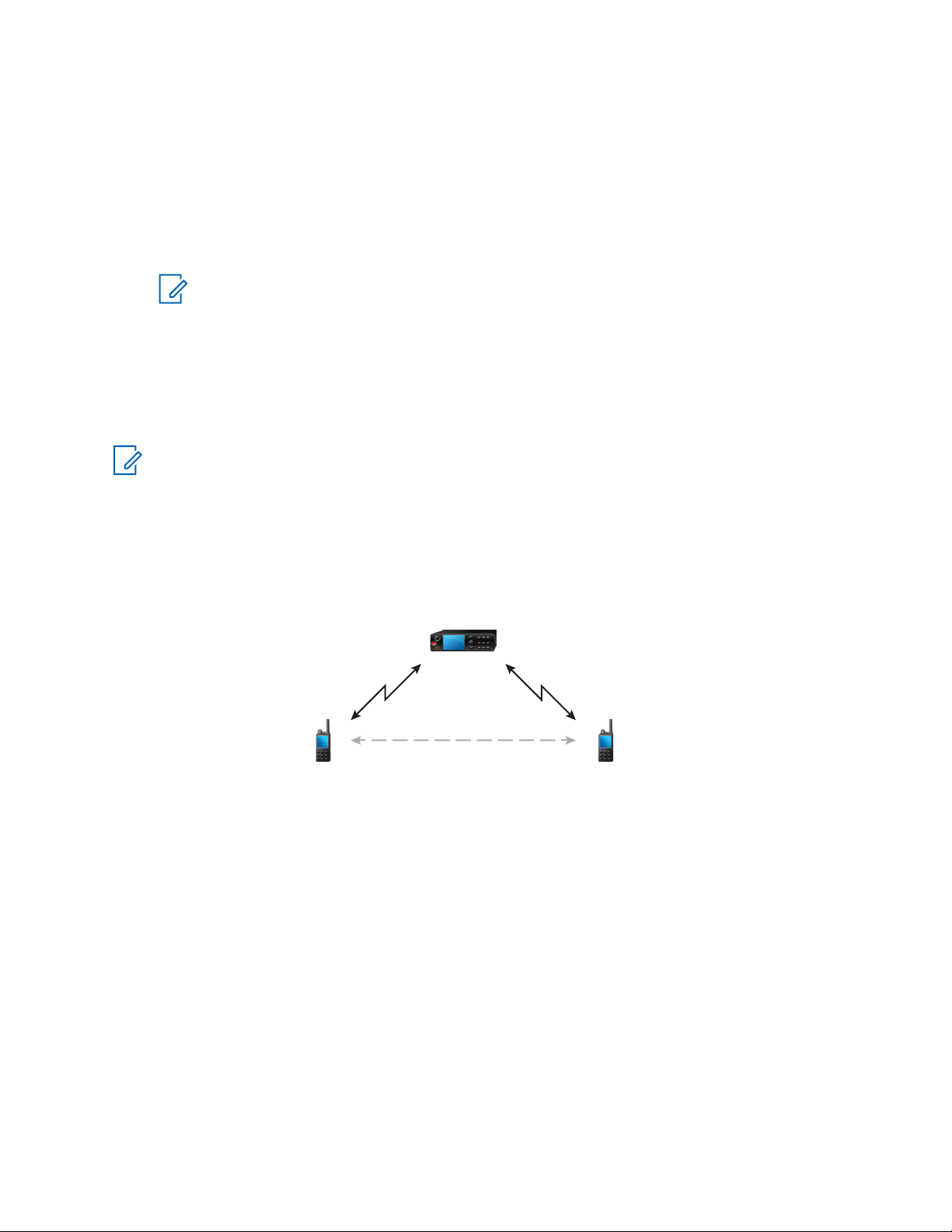
DMODMO
MN002041A01–AA
Chapter
3.5.16
3: Modes
Exiting Emergency Operations
Prerequisites: Make sure that your radio is engaged in Emergency Operations.
Procedure:
1 If your radio screen displays Emergency Mic On, press End.
2 Press and hold Exit.
NOTICE: If an Emergency Operation was triggered by Emergency number (not by
EMERGENCY button), you can press the END key to exit the Emergency Operation.
3 If your radio displays Do you want to exit?, press Yes to exit.
Your radio exits Emergency Operations.
3.6
Repeater Mode
NOTICE: This is a selling feature.
The Repeater Mode provides repeater connectivity between radios operating in the DMO Mode.
Figure 7: Repeater Mode Operation
A DMO repeater is used to extend the DMO range by retransmitting received information from one
radio to another. It retransmits group calls, private calls and data on a given frequency. In the diagram
above the radio in the middle is a repeater.
The repeater sends presence signal periodically on a free channel to allow other radios to synchronize
on a given frequency.
Only the radios on the same talkgroup can communicate with each other through the repeater.
The Repeater Mode is activated by selecting
MENU → Networks → Repeater Mode.
3.6.1
Setting Monitor Option
Procedure:
1 From the home screen, press Optns.
74 Send Feedback
Page 75

MN002041A01–AA
Chapter 3: Modes
2 Press Monitor.
3 Select one of the following:
• Off — Your radio works as a repeater only, no operation is available.
• Receive Only — Allows you to listen.
• Receive&Transmit — Allows you to listen and transmit by pressing
3.6.2
PTT.
Encryption in the Repeater Mode
While in the Repeater Mode, the radio supports Air Encryption and is able to repeat encrypted calls
and messages.
If SCK keys installed on the radio are invalid:
• The radio transfers calls and messages without deciphering them (provided that the encryption level
is not the highest).
• The LED indicator turns orange.
• On pressing the PTT button, Channel Busy or DMSCK is Invalid message appears.
• You cannot make any call.
Send Feedback 75
Page 76

This page intentionally left blank.
Page 77

MN002041A01–AA
Global Navigation Satellite System (GNSS)
Location Service
Chapter 4
Global Navigation Satellite System (GNSS) Location Service
NOTICE: This is a selling feature.
The Global Navigation Satellite System (GNSS) Location Service feature uses information from GNSS
satellites orbiting the Earth to determine the approximate geographical location of your radio.
The GNSS Location Service availability, accuracy, and the position calculation time vary depending on
the environment in which you use the radio. The
colleagues in many ways such as more efficient deployment of resources or locating your radio when
you trigger your emergency service.
The radio can display the location information directly on the screen or send it over the air to your
dispatcher to display it in the control center. Check your radio configuration details with your service
provider.
The radio supports the following system combinations:
• GPS
• GLONASS
• BeiDou
• GPS + GLONASS
• GPS + BeiDou
IMPORTANT: Where the signals from satellites are not available, the
does not work. This situation usually happens when your radio cannot establish a view of a
wide area of open sky, for example, when the GNSS antenna is covered or facing the ground.
Such situations include being:
• In underground locations
• Inside buildings, trains, or other covered vehicles
• Under any other metal or concrete roof or structure
• Near a powerful radio or television tower
• In extreme temperature outside the operating limits of your radio
Even if your location information can be calculated in such situations, it may take longer to do so.
Therefore, in any emergency situation, always report your location to your dispatcher. Where adequate
signals from multiple satellites are available, your GNSS Location Service feature provides a location,
most probably near to your actual location.
The radio can be triggered to send Location Reports in various circumstances, for example:
• Upon a request
• Entering Emergency Mode
• At specified time intervals
• At specified distance intervals
The Location Reports can be sent both in TMO and DMO by using:
• SDS messages
GNSS Location Service can assist your dispatcher or
GNSS Location Service
Send Feedback 77
Page 78

MN002041A01–AA
Chapter 4: Global Navigation Satellite System (GNSS)
• Packet Data (in TMO mode only, with Packet Data enabled on the network by the service provider)
The radio can be configured to give audio-visual notifications upon sending the Location Reports.
Depending on the radio settings, viewing the radio position and the status of the visible satellites is
available. The position may consist of longitude and latitude, UK, or Irish grid coordinates.
4.1
Enhancing
Sometimes the GNSS feature is unable to complete a location calculation successfully. You hear an
audible tone indicating that your radio cannot see the satellites.
To maximize the ability of your radio to determine a location fix please note the following guidelines:
• Stay in the open — The GNSS feature works best where there is nothing between your radio and a
large amount of open sky. If possible, go outside, away from tall buildings and foliage. While the
performance in a building is improved by moving closer to windows, glass with certain sun shielding
films may block satellite signals.
• Position your radio to enhance reception — Signals from GNSS satellites are transmitted to your
GNSS antenna, which is in your radio antenna. Hold your radio away from your body, giving the
antenna clear access to satellite signals. Do not cover the antenna area with your fingers or
anything else.
• Stand still — If possible, stand still until your radio is finished determining your location. Moving your
radio at a walking pace while your radio is calculating your approximate location may substantially
decrease GNSS performance.
This feature works best where there is nothing between your radio and a large amount of open sky. To
maximize the ability of your radio to determine a location fix, avoid closed space, tall buildings, and
foliage. If possible, do not use GNSS in underground parking lots, tunnels, under bridges, and close to
high buildings.
GNSS Performance
Location Service
4.2
Enabling GNSS
Procedure:
1 From the home screen, press the MENU key.
2 Select Location → Interface.
3 Select On.
NOTICE: Your service provider can enable this feature.
4.3
GNSS Icon
When GNSSis enabled, the following icon is displayed in the status icon area: Depending on the
current GPS/GNSS state, the icon can be solid – GPS/GNSS has a fix, or blinking – GPS/GNSS is
searching for a fix. The blinking GPS/GNSS icon can be disabled/enabled by your service provider.
78 Send Feedback
Page 79

Chapter
4.4
Different Location Displays
Table 17: Different Location Displays
MN002041A01–AA
4: Global Navigation Satellite System (GNSS) Location Service
Latitude / Longitude
Time Time Time Time Time
Latitude 2–Letter Code 1–Letter Code 3–Letter Code 3–Letter Code
Longitude Easting and
Altitude Altitude Altitude Altitude Altitude
Satellites Satellites Satellites Satellites Satellites
• Time — indicates when the last time the location was calculated. The time is provided in Universal
Time Coordinated.
Letter Code — grid zone or square on the map for different coordinate standard
•
• Latitude — expressed in degrees, minutes, and seconds.
• Longitude — expressed in degrees, minutes, and seconds.
• Number of satellites — used to calculate the location. In general, more satellites make for better
accuracy. The maximum is 12 satellites. Satellites used are displayed as x/x.
• Easting — refers to the eastward-measured distance expressed in meters.
• Northing — refers to the northward-measured distance expressed in meters.
• UTM — refers to Universal Transverse Mercator coordinate system
• MGRS — refers to Military Grid Reference System.
UK Coordinates
Northing Coordinate
Irish Coordinates
Easting and
Northing Coordinate
UTM Coordinates
Easting and
Northing Coordinate
MGRS Coordinates
and 2–Letter
Code
Easting and
Northing Coordinate
NOTICE: Skipping each digit of easting and northing coordinates decreases the accuracy by
the factor of 10.
4.5
Viewing Your Position
Procedure:
1 From the home screen, press the MENU key.
2 Select Location
3 Scroll to view the results about the last time your location was calculated.
NOTICE: To refresh your position:
•
• Press Refresh
Send Feedback 79
→ Position.
Select Position — the radio refreshes its position automatically
Page 80

MN002041A01–AA
Chapter 4: Global Navigation Satellite System (GNSS)
4.6
Changing GNSS
Procedure:
1 From the home screen, press the MENU key.
2 Select Location → Accuracy.
3 Select one of the following:
• Medium (default) – Power consumption optimization is combined with less position accuracy.
• High – Better position accuracy is combined with less power consumption optimization.
NOTICE: If connected to an external charging device, the radio automatically enters the
High mode.
4.7
Accuracy
Location Service
Viewing Testpage
Procedure:
1 From the home screen, press the MENU key.
2 Select Location → Testpage.
3 Select one of the following:
• Position – displays detailed information on radio’s current position: time, N
(longitude), H (height), Sats Used (a number of tracked satellites), B (bearing), HS
(horizontal speed), LC (level of confidence).
• Power – displays detailed information on a particular satellite: PRN code, Status, Mode, C/N
(carrier-to-noise ratio).
• Version – displays detailed information on software version: SW (software version), HW
(hardware version), ASIC (application-specific integrated circuit), RC (release code).
(latitude), E
80 Send Feedback
Page 81

MN002041A01–AA
Main Menu
Chapter 5
Main Menu
This chapter contains information on items in the main menu.
You can enter the menu items during a call. If not programmed otherwise by your service provider the
radio exits the menu, when a new call starts.
IMPORTANT: Some menu items are model specific and may not be activated or available on
your radio.
5.1
Scrolling through the Menu
Procedure:
1 From the home screen, press the MENU key.
2 Scroll to the required item by pressing
or right NAVIGATION key to select.
If the menu item contains a further set of menu items, repeat step 2.
NOTICE: You can use shortcuts to access frequently used items.
NAVIGATION keys. Press the SOFT key assigned as Select
5.2
Menu Icons
The following icons make it easy to identify the menu items at first glance.
Table 18: Menu Icons
Menu Icon Description
Main Menu Items / Context Sensitive Menu
It is assigned to MENU when the main menu items / context-sensitive menu are
active.
Messages
Send status messages,
Send text messages (free text or according to user defined or predefined
templates),
Received messages in Inbox.
Contacts
Add, search, edit, or erase entries in the contact list.
Pictures
Allows you to browse and manage photos.
Bluetooth
Allows you to manage Bluetooth settings.
Table continued…
Send Feedback 81
Page 82

MN002041A01–AA
Chapter
Menu Icon Description
5: Main Menu
Browser
Starts the WAP browser.
Man Down
Allows you to activate the Man Down feature.
Security
Lets you turn on/off and verify security features, and change passwords.
Setup
Allows you to customize your radio.
Group Setup
Contains additional menu items for Scanning Talkgroups features.
Favorites
Contains shortcuts to frequently used talkgroups and contact numbers.
My Info
Displays information about your radio and its numbers.
5.3
Messages
Recent Calls
Contains a list of recent calls.
Shortcuts
Allows you to view and manage shortcuts to menu items.
RUI
Allows you to log in and log out of the radio.
Networks
Allows you to select a network.
Location
Displays location of your radio.
Packet Data
Allows you to send data from your radio to other devices.
Services
Allows you to manage Broadcast, Assistance and Disaster Calls.
This feature allows you to send and receive text messages. A message can contain up to 1000
characters, depending on your service provider settings.
Pressing the
depending on your service provider settings:
• The radio ignores the PTT button request.
82 Send Feedback
PTT button when a message is highlighted can cause one of the following actions,
Page 83

• The radio starts a Private Call with the message sender.
The radio starts a Group Call on a currently selected talkgroup.
•
5.3.1
New Message
This menu item allows you to create a new message.
5.3.1.1
Sending Messages to Private/Phone
Procedure:
1 From the home screen, press the MENU key.
2 Select Messages → New Message.
3 Enter your message and press Send.
4 If needed, select Private/Phone.
5 Enter recipient number or press abc to choose it from your contacts.
NOTICE:
For Private target selection, you can enter either Individual Short Subscriber Identity
(ISSI) or Group Short Subscriber Identity (GSSI) of the recipient.
ISSI – a unique, individual ID assigned for each radio.
GSSI – in Dimetra called Group ID or Talkgroup ID.
6 Press Send, or SEND key, or the PTT
button.
MN002041A01–AA
Chapter 5: Main Menu
5.3.1.2
Sending Messages to Groups
Procedure:
1 From the home screen, press the MENU key.
2 Select Messages → New Message.
3 Type your message and press Send.
4 If needed, select Group.
5 Select a group to send the message.
5.3.1.3
Sending Store and Forward Messages
Prerequisites: Your service provider enables the Store and Forward feature.
Procedure:
1 From the home screen, press the MENU key.
2 Select Messages → New Message.
3 Press MENU key and select Message Setup → On/Offline users.
4 Enter your message and press Send.
5 If asked for the Target selection, select one of the following:
Send Feedback 83
Page 84

MN002041A01–AA
Chapter
5.3.1.4
5: Main Menu
• Private – enter the private number or press abc to choose the destination number from the
contact list.
• Phone – enter the phone number or press abc
contact list.
NOTICE: Your service provider can enable to send a Store and Forward message to a
talkgroup.
6 Select Send, or press SEND key or PTT button.
to choose the destination number from the
Delivery Report
Delivery Report is an acknowledgment that the radio can request upon sending a message to an
individual recipient. You can define what type of Delivery Report your radio requests, or turn on/off this
feature.
If the Delivery Report is received shortly after the message was sent, the radio:
•
Displays a pop-up with one of the following messages:
- Message Sent – if no Delivery Report is requested (and when a Store and Forward message
has been received at the Store and Forward server)
- Message Delivered – if the Delivery Report is requested and the message has been received
by the target radio
- Message Read
– if the Consumed Delivery Report is requested and the message is opened on the target radio
- Message Failed – if the Delivery Report is requested and the message has not been received
by the target radio within a defined time period
• Saves the Delivery Report in Outbox along with a copy of the message.
If the Delivery Report is received after a longer period of time, the radio:
• Saves the Delivery Report in Outbox along with a copy of the message.
• If Delivery Report Notifications functionality is configured by your service provider, the radio also:
- Temporarily saves a Delivery Report message in Inbox. The notification disappears after it is
read.
- Displays New Message icon.
- Displays New Delivery Status notification screen (if possible).
5.3.1.5
Viewing Delivery Reports
Procedure:
1 From the home screen, press the MENU key.
2 Select Messages → Inbox.
3 Find a required message and select Read.
4 Press MENU key.
5 Select Delivery Status.
84 Send Feedback
Page 85

5.3.1.6
Configuring Delivery Reports
Prerequisites: Your service provider enabled the delivery report configuration.
Procedure:
1 From the home screen, press the MENU key.
2 Select Messages → New Message.
3 Press MENU key and select Delivery Report.
4 Select one of the following:
• None — the radio does not request any delivery report.
• Received — the radio requests reports on your messages that were received.
• Consumed — the radio requests reports on your messages that were read.
• Both — the radio requests reports on your messages that were received and read.
5.3.2
Inbox
MN002041A01–AA
Chapter
5: Main Menu
It contains up to 100 new or old incoming messages, depending on the length of the messages.
Table 19: Inbox Icons
Icon Description
Unread (New) Message
Read (Old) Message
Sender Information in Message View — name or number
Time and Date Stamp in Message View — arrival time and date
Delivery Status Received — delivery status for Store & Forward messages
Messages sub-menu indicates the number of the messages. If the indication is for example 2/4, it
means that two unread and four read messages are in the Inbox.
5.3.2.1
Entering the Inbox
Procedure:
1 From the home screen, press the MENU key.
2 Select Messages
NOTICE: The status (if any) of the list is displayed for a few seconds:
• No New or Old Messages — The screen returns to the previous display within a few
seconds.
• Inbox Full — Select Ok.
Send Feedback 85
→ Inbox.
Page 86

MN002041A01–AA
Chapter 5: Main Menu
5.3.2.2
Receiving New Messages
Prerequisites: Your radio displays a New Message icon, an animation, and plays a New Mail
Received tone.
Procedure:
Select one of the following:
• Read — opens the entire message.
• Back — dismisses the message. You can access the message later from the Inbox.
5.3.2.3
Using Submenus in the Inbox and the Outbox
Procedure:
1 From the home screen, press the MENU key.
2 Select Messages → Inbox or Outbox.
3 Highlight the required message and press
4 Select one of the following:
• Store — Saves a message as a template. Change the default template name and press Ok.
• Delete — Deletes the selected message. Press Yes to confirm.
• Delete All — Deletes all the messages in the Inbox/Outbox. Press Yes to confirm.
• Reply (only for Inbox) — Invokes the edit screen with the old message as default text and
the message originator as a recipient. After editing, press Send, the PTT button, or the SEND
key to send.
• Resend (only for Outbox) — Invokes the edit screen with previously entered text with the
same recipient. After editing, press Send, the PTT button, or the SEND key to send.
• Forward — Invokes the edit screen with the old message to send it to a different participant.
After editing, press Send, the PTT button, or SEND key to send.
• Refresh — Re-orders the message list and displays the new messages.
• Delivery Status (only for Outbox) — Shows the date and time of the message when it sent,
delivered, read, and expired was not delivered, expired was not read, failed unknown.
MENU key.
5.3.2.4
Embedded Number
This feature allows you to call a number from a message or to start a group call with the message
sender talkgroup.
5.3.2.5
Storing Numbers from Messages
Prerequisites: Embedded Number feature is enabled by your service provider.
When and where to use: You can save the sender's or embedded number from the message to a
new or existing contact.
Procedure:
1 From the home screen, press the MENU key.
86 Send Feedback
Page 87

MN002041A01–AA
Chapter 5: Main Menu
2 Select Messages → Inbox.
3 Highlight the required message and select Read.
4 Press the PTT button.
5 Radio displays a list of the numbers (including the senders number).
6 Highlight the required number and press Store.
7 Highlight required contact and press View.
NOTICE: To store a number for a new contact, select [New Contact] and fill out the
required fields. Press Done to save it..
8 Select Edit.
9 Choose the Type of the new number and press Done.
5.3.2.6
Calling Numbers in Messages
Prerequisites: Embedded Number feature is enabled by your service provider.
When and where to use: You can return a voice call to the sender of a message or to any number
that is embedded in the message text.
Procedure:
1 From the home screen, press the MENU key.
2 Select Messages → Inbox.
3 Highlight the required message and select Read.
4 Press the PTT
5 Radio displays a list of the numbers (including the senders number).
6 To call, highlight to the required number and press the PTT button or the SEND key.
7 Select Ctype to choose the type of call (Private, Phone, or PABX).
8 Press the PTT button or the SEND key.
5.3.2.7
button.
Making Group Calls on theTalkgroup of the Message Sender
Prerequisites: Embedded Number feature is enabled by your service provider.
Procedure:
1 From the home screen, press the MENU key.
2 Select Messages → Inbox.
3 Highlight the required message and press the PTT button.
5.3.2.8
Immediate Message
NOTICE: This is a selling feature.
When the new immediate message is received, radio plays the New Mail Received tone and displays
the content overlapping your previous screen. All immediate messages are stored in the Inbox. If the
radio is in PIN Lock state, immediate message is displayed after correct PIN is entered.
Send Feedback 87
Page 88

MN002041A01–AA
Chapter
The message stays on the screen until you press the End/Home key.
5.3.3
5: Main Menu
Outbox
Outbox stores up to 100 sent messages arranged chronologically with the last sent message at the top
of the list.
Table 20: Outbox Icons
Icon Description
Delivery in Progress
Delivery Accomplished
Delivery Failed
Successful Outgoing Message
Failed Outgoing Message
5.3.4
CO Box
CO Box contains incoming and outgoing Call-Out messages. Clicking Select
headline displays more detailed information on the item.
When the radio is in normal mode, you are able to browse through all messages in the CO Box.
However, if the radio is in the Call-Out mode, you can only browse through the information regarding
the currently ongoing Call-Out message.
5.3.5
on a Call-Out message
RMS Box
RMS Box stores all incoming and outgoing Radio Messaging System (RMS) messages, both Status
messages and Free Text messages.
5.3.6
WAP Box
Each WAP Push message can be loaded immediately or stored as a message in WAP Box. Then it
can be accessed by pressing MENU → Messages → WAP Box. All the WAP Push messages are
passed to the browser.
5.3.7
Templates
Templates box stores user-defined message templates. Each of the Inbox and Outbox message can
be stored as a template. Each template name and text can be edited afterwards.
88 Send Feedback
Page 89

Chapter 5: Main Menu
5.3.7.1
Sending User-Defined Templates
Procedure:
1 From the home screen, press the MENU
2 Select Messages → Templates.
3 Highlight the required template name and press Send.
4 Do one of the following:
• Enter the number or press abc to select the name from your contact list. Press Send.
• Select required talkgroup from the TalkGroup List.
5.3.7.2
key.
Managing User-Defined Templates
Procedure:
1 From the home screen, press the MENU key.
2 Select Messages → Templates.
3 Highlight the required template and press MENU.
4 Select one of the following:
• View — Displays template text.
• Delete — Deletes the template.
• Edit Text — Opens edit screen with the template text. Edit the text and press MENU. Select
Save Changes to save edited template, or Store to save the edited template as a new one.
• Edit Name — Opens edit screen with the template name. Press Ok to save the template.
MN002041A01–AA
5.3.8
Predefined Templates
Predefined message templates are programmed into your radio. You are allowed to perform limited
edit operations of the predefined template. You can send it, but you are not able to store the edited
template or erase it from the predefined template list.
5.3.8.1
Viewing Predefined Templates
Procedure:
1 From the home screen, press the MENU key.
2 Select Messages → Predefined.
3 Highlight the required template and press MENU key.
4 Select View.
5.3.8.2
Sending Predefined Templates
Procedure:
1 From the home screen, press the MENU key.
Send Feedback 89
Page 90

MN002041A01–AA
Chapter 5: Main Menu
2 Select Messages → Predefined.
3 Highlight the required template and press Send, the
NOTICE: You can edit the predefined template before you send it. Press the
and select Edit. Edit screen opens with the template text. You are only allowed to
replace the existing text.
5.3.9
PTT button, or the SEND key.
MENU key
Status Messages
The radio allows you to send two types of status messages: statuses and targeted statuses. Your
service provider determines which type is enabled on the radio.
Statuses can be sent either to a selected talkgroup or to a private number programmed by your service
provider. Targeted statuses can be sent to any talkgroup defined for the radio or to any private number
(from the contact list or entered manually).
5.3.9.1
Viewing a Status Message Number
Procedure:
1 From the home screen, press the MENU key.
2 Select Messages → Send Status.
3 Press the MENU key and select View.
5.3.9.2
Sending Status Messages
This procedure allows you to send status messages to either a selected talkgroup or a programmed
private number. Only one option can be enabled at a time.
Prerequisites:
• If sending statuses to talkgroups is enabled: switch to the talkgroup to which you want to send a
status message.
• If sending statuses to private numbers is enabled: no action is needed, the private number is set up
by your service provider
Procedure:
1 From the home screen, press the MENU key.
2 Select Messages → Send Status.
3 Do one of the following:
• Highlight the required status message and press Select, the PTT button, or the SEND key.
• If the status list is empty, enter a 5 digit status message number and press Send.
4 Highlight the required status message and press Select, the PTT button, or the SEND key.
5.3.9.3
Targeted Status Messages
This feature enables sending status messages to user selectable addresses. By default, targeted
status messages can be sent to private or talkgroup addresses. Your service provider may restrict valid
addresses to numbers stored in Contacts.
90 Send Feedback
Page 91

MN002041A01–AA
Chapter 5: Main Menu
NOTICE: This feature is not supported on Dimetra networks.
5.3.9.4
Sending Targeted Status Messages
Procedure:
1 From the home screen, press the MENU key.
2 Select Messages
3 Do one of the following:
• Highlight the required status message and press Select, the PTT button, or the SEND key.
• If the status list is empty, enter a 5 digit status message number and press Send.
4 Highlight the required status message and press Select, the PTT button, or the SEND key.
5 Do one of the following:
• Enter the number or press abc to select the name from your contact list. Press Send.
• Select required talkgroup from the TalkGroup List.
The display shows one of the following delivery reports:
• Status Sent.
• Status Failed.
→ Send Status.
5.3.10
Additional Address
The Additional Address feature allows the radio to send RMS messages, and Local Information
Protocol (LIP) reports to additionally defined recipients.
The default addresses where the radio sends RMS messages and LIP reports are defined by your
service provider. If an Additional Address is selected and enabled, RMS messages and LIP reports are
also sent to the recipient defined in the Additional Address.
You can create, edit, and delete Additional Addresses using the radio menu. If an Additional Address is
configured by your service provider, the service provider can disable edition and deletion of the
address using the radio menu.
You can define up to 30 Additional Addresses.
5.3.10.1
Enabling/Disabling Additional Address
Procedure:
1 From the home screen, press the MENU key.
2 Select Messages → Additional Address → Enable.
3 Select one of the following:
• On – to activate the feature
• Off – to deactivate the feature
Send Feedback 91
Page 92

MN002041A01–AA
Chapter
5.3.10.2
5: Main Menu
Selecting Additional Address
Procedure:
1 From the home screen, press the MENU key.
2 Select Messages → Additional Address → Select Address.
Select Address
3 Scroll through the list to highlight your alias and press Select.
5.3.10.3
display appears with an available list of aliases.
Viewing Additional Address
Procedure:
1 From the home screen, press the MENU key.
2 Select Messages → Additional Address → Select Address.
3 Scroll to select the alias of the Additional Address you wish view.
4 Press the Menu key.
5 Select:
• Edit (for User Defined Additional Address alias)
• View(for Pre-defined Additional Address alias)
The display shows the Alias, the ISSI/GSSI and the Status of the address (Pre-Defined or User
Definded).
5.3.10.4
Entering New Additional Address
Procedure:
1 From the home screen, press the MENU key.
2 Select Messages → Additional Address → Select Address.
3 Select [New Address]
4 Press Change key.
5 Enter new values of the Alias and ISSI/GSSI fields, press Done key.
The new alias appears in the list of available aliases. There is no possibility to have two Additional
Address items with the same Additional Address Alias.
5.3.10.5
Editing Additional Address
Prerequisites: Editing Additional Address is allowed only for User-Defined positions. Pre-Defined
positions can only be Selected or Viewed.
Procedure:
1 From the home screen, press the MENU key.
2 Select Messages → Additional Address → Select Address.
3 Highlight the alias.
92 Send Feedback
Page 93
MN002041A01–AA
Chapter
4 Press Menu key.
5 Select Edit.
6 Press Change.
7 Enter new values of the Alias and ISSI/GSSI fields, press Done key.
The changed alias appears in the list of available aliases. There is no possibility to have two Additional
Address items with the same Additional Address Alias.
5.3.10.6
5: Main Menu
Deleting Additional Address
Prerequisites: Deleting Additional Address is allowed only for User-Defined positions. Pre-Defined
positions can only be Selected and Viewed.
Procedure:
1 From the home screen, press the MENU key.
2 Select Messages → Additional Address
3 Scroll to select the alias of the Additional Address you wish delete.
4 Press the Menu key.
5 Select Delete and confirm deletion by the OK key.
→ Select Address.
5.4
Contacts
This sub-menu stores all your contact numbers. Each entry requires the following information:
• Name — if you store more than one number to one contact, this entry is required.
• Type — each contact must be assigned to one of the following types:
Table 21: Contact Types
Contact Icon Description
Private
Cannot have a speed dial number.
Mobile
Home
Work
PABX
Other
Pickers
Indicate more than one number in a contact.
Send Feedback 93
Page 94

MN002041A01–AA
Chapter
• # (number) — each contacts entry must contain a number.
• Speed # — accept the default Speed Dial number or change it.
5.4.1
5: Main Menu
Creating Contacts
Procedure:
1 From the home screen, select Contcs.
2 Select [New Contact].
3 Highlight Name and press Change. Enter the name of your contact and press Ok.
4 Highlight Type and press Change. Select the required type of your contact.
NOTICE: You can use the left and right NAVIGATION keys to select the type of your contact
from the Contact Details screen.
5 Highlight #
6 If needed, highlight Speed # and press Change. Enter the speed dial number (1– 1000) of your
contact and press Ok.
7 Press Done.
You have create a contact with one number. To add additional number repeat steps 4–6.
5.4.2
(number) and press Change. Enter the number of your contact and press Ok.
NOTICE: If the entered number exist, the radio displays Overwrite? message. Press
Yes to confirm, or No to enter the speed dial number again.
Editing Contacts
Procedure:
1 From the home screen, press Contcs.
2 Highlight the contact you want to edit.
3 Press the MENU key.
4 Press Edit.
5 Highlight one of the following entries and press Change to edit:
• Name
• Type
• # (number)
• Speed #
6 Press Done.
5.4.3
Deleting Numbers
Procedure:
1 From the home screen, press Contcs.
2 Select a contact you want to edit.
3 Use left or right NAVIGATION keys to choose the required number.
94 Send Feedback
Page 95

4 Press MENU.
5 Select Delete number.
NOTICE: If an entry contains only one number, deleting the number deletes the entry.
6 Press Yes.
5.4.4
Deleting Contacts
Procedure:
1 From the home screen, select Contcs.
2 Highlight a contact you want to delete.
3 Press the
4 Select Delete contact.
5 Select Yes.
5.4.5
MENU key.
Checking Capacity
MN002041A01–AA
Chapter 5: Main Menu
When and where to use: To see how many numbers are stored in the radio.
Procedure:
1 From the home screen, select Contcs.
2 Press the MENU key.
3 Select Capacity.
4 Select one of the following:
• Private
• Phone / PABX
• Contact
5.4.6
Dialing through the Contact List
Procedure:
1 From the home screen, press Contcs.
2 To highlight the required contact, use up and down NAVIGATION keys, or enter up to 12 characters
of the contact name.
3 If the contact has more than one number, use left and right NAVIGATION keys to select the
required number.
4 Press the PTT button to initiate a simplex call with a Private number. Otherwise use the SEND
key to initiate a duplex call.
Send Feedback 95
Page 96

MN002041A01–AA
Chapter 5: Main Menu
5.5
Pictures
This menu item activates the Picture Browser. The Picture Browser is an application that allows you to
browse through pictures saved on the microSD card or in the internal radio memory and send them to
other devices by using Bluetooth. Unless the Digital Fingerprint feature is enabled, you can also add
comments or edit exiting ones.
The Picture Browser has two views:
The multi-picture view – displays thumbnails of pictures and folders.
•
• The full screen view – displays one picture that is scaled to fit the display. This view also allows
zooming in and out of pictures.
Picture Browser displays pictures only in the JPEG format, that is files with .jpg and .jpeg extensions.
Also, the browser does not open pictures whose size exceeds 10 MB – File too large message is
displayed.
5.5.1
Starting the Picture Browser
Procedure:
1 From the home screen, press the MENU key.
2 Select Pictures.
The Picture Browser starts.
5.5.2
Navigation in the Picture Browser
Table 22: Navigation in the Multi-Picture View
I want to... Action
Highlight another item. Rotate the ROTARY KNOB or use the NAVIGATION
keys.
NOTICE:
If the first item in the folder is highlighted and you press the left/down
TION key or rotate the ROTARY KNOB an-
ticlockwise, the highlight moves to last
item in the folder.
If the last item in the folder is highlighted and you press the right/down NAVI-
GATION key or rotate the ROTARY KNOB
clockwise, the highlight moves to first
item in the folder.
Display content of a folder. Highlight a folder and press Select or the ROTA-
RY KNOB.
NAVIGA-
Return the previous folder / go up one folder
level.
96 Send Feedback
Highlight the folder in the upper left corner of the
display (with three dots) and press Select.
Table continued…
Page 97

MN002041A01–AA
Chapter
5: Main Menu
Display a picture in the full screen view.
Return to the main menu. Press Exit.
View additional picture options. Highlight a picture and press MENU key.
Table 23: Navigation in the Full Screen View
I want to... Action
Display the previous picture. Press the left NAVIGATION key.
Display the next picture. Press the right NAVIGATION
Zoom a picture in by one level.
Zoom a picture out by one level.
• Highlight a picture and press View,
or
Highlight a picture and press the ROTARY
•
KNOB.
key.
• Press the * key, or
• Rotate the ROTARY KNOB clockwise.
• Press the # key, or
• Rotate the ROTARY KNOB anticlockwise.
NOTICE: When a picture is
zoomed out to maximum, the
browser returns to the full screen
view.
Move the displayed area of the zoomed picture.
Return to the full screen view (from the zoomed
view).
Return to the multi-picture view.
Remove a picture. Press Delete.
5.5.3
Press the NAVIGATION
• Press Cancel,
or
• Press the ROTARY KNOB.
• Press Back,or
• Press the ROTARY KNOB.
keys.
Zoom Levels
The Picture Browser displays pictures at five zoom levels:
First – whole picture preview, this is the default zoom level for the full screen view.
•
• Second – a picture zoomed in 2x.
• Third – a picture zoomed in 4x.
• Fourth – a picture zoomed in 8x.
• Fifth – the maximum zoom level.
Resolution of pictures exceeding 2MP will be halved for the display purposes (original picture will not
be modified).
Zooming in is not available if the picture size is smaller than the display resolution.
Send Feedback 97
Page 98

MN002041A01–AA
Chapter
5.5.4
5: Main Menu
Adding/Editing Comments to Pictures
The maximum length of a comment to be added is 144 characters. Adding and editing comments is
disabled if the Digital Fingerprint feature is active or if the picture size exceeds 3 MB.
When and where to use:
To add a new or edit an existing comment assigned to a picture.
Procedure:
1 From the home screen, press the MENU key.
2 Select Pictures.
3 Highlight the required picture.
4 Press the MENU
5 Select Comment.
6 Enter a new comment or edit an existing one.
7 Press Save to confirm changes.
5.5.5
key.
Sending Pictures via Bluetooth from the Picture Browser
By using this procedure you can send JPEG files displayed in the Picture Browser. To send other types
of files via Bluetooth, go to My Received Files; for details see Sending Files via Bluetooth from My
Received Files on page 103
Procedure:
1 From the home screen, press the MENU key.
2 Select Pictures.
3 Highlight the required picture and press the MENU key. The maximum file size is 2 GB.
4 Select Send.
5 Perform one of the following actions:
If… Then…
If the paired devices list is empty, wait until the radio displays the list and then high-
light the required recipient device and press Connect.
If the required recipient device is
present on the paired devices list,
If the required recipient device is
not present on the paired devices
list,
highlight the device and press Select.
perform the following actions:
a Refresh the list by selecting Search.
b Highlight the device and press Connect.
File is sent in the background. Once the transfer is complete, the radio terminates connection with the
remote device.
98 Send Feedback
Page 99

5.6
Bluetooth
MN002041A01–AA
Chapter
5: Main Menu
NOTICE: Bluetooth Audio
Control are selling features.
There are three separate Bluetooth features available:
•
Bluetooth Audio and Object Push - includes: Bluetooth Audio, Object Push Profile (OPP), Fast PTT,
and Indoor Location
• Bluetooth Connectivity - includes: Bluetooth Serial Port Profile (SPP) and Bluetooth Dial Up
Networking (DUN)
• Bluetooth Radio Control - includes: Bluetooth Radio Control via AT commands
You can use Bluetooth to:
• Connect the radio with wireless accessories, for example a headset, which gives you a greater
freedom of movement and increases your work comfort. Additionally, wireless accessories allow
performing the same activities in several ways. For example, you can change the volume level
either in the headset or on the radio.
• Send and receive files via the Object Push Profile (OPP).
• Make your radio discoverable indoors to Bluetooth beacons.
• Allow radio collaboration with various BT sensors or data capture devices e.g. biometric sensor, bar
code scanner or firearm device.
• Increase connectivity by means of secure packet data services between the radio and a PDA
device or a Smartphone running appropriate applications.
• Enable radio control via a PDA device.
Depending on the hardware configuration, radios supports Bluetooth 2.1 + EDR, Bluetooth 4.0, and
Bluetooth Smart (BTLE). Secure Simple Pairing, one of its features, ensures high level of security while
pairing devices and thus protects you against recording and passive eavesdropping.
Bluetooth operating range is approximately 10 meters. The usable range may be reduced if you
connect the radio with devices that support more limited ranges or if physical obstacles such as walls
appear between devices.
One radio can be connected with up to seven devices at the same time.
and Object Push, Bluetooth Connectivity and Bluetooth Radio
5.6.1
Bluetooth Interactions
The following features and situations limit the use of Bluetooth:
Transmit Inhibit Mode (TXI), Repeater Mode
Bluetooth does not work in the Transmit Inhibit Mode nor in the Repeater Mode. When the radio
enters one of those modes while Bluetooth is enabled, all remote devices are disconnected and
Bluetooth is disabled. After leaving the TXI or the Repeater Mode, Bluetooth is enabled again (if it
was previously turned on).
Covert Mode
The radio cannot enter Discoverable Mode while in the Covert Mode (the Covert Mode has a higher
priority).
Wired Audio Accessories
Wired audio accessories have a higher priority than Bluetooth audio accessories. If both types of
devices are connected to the radio, it disconnects the Bluetooth audio device. When a wired audio
device is already connected to the radio, scanning for Bluetooth audio devices is disabled.
Send Feedback 99
Page 100

MN002041A01–AA
Chapter
5.6.2
5: Main Menu
Enabling and Disabling Bluetooth
Procedure:
1 From the home screen, press the MENU key.
2 Select Bluetooth → Bluetooth: On / Bluetooth: Off.
3 Select On to enable, or Off
When Bluetooth is enabled, the Bluetooth icon appears in the status icon area on the display.
However, the Bluetooth icon may not be visible at times, due to other icons with higher priority
being displayed in the same icon slot.
NOTICE:
Your service provider may configure the radio to automatically disable Bluetooth after
entering the home mode. The home mode is a state in which all the following conditions
are met: the radio is not in the Discoverable Mode, all active remote devices are
disconnected (including file transfer), and scanning for remote devices is not performed.
5.6.3
to disable Bluetooth.
Discoverable Mode
When the radio is in the Discoverable Mode, it is visible to other Bluetooth-enabled devices. Also, it
accepts connection requests from other devices attempting to send files to your radio or to establish a
DUN connection or start a remote control or AT Command session over Bluetooth. If enabled, the
following item appears in the radio menu: Discoverable (Menu
Discoverable). The radio remains discoverable for the amount of time configured by the user.
5.6.4
→ Setup → Bluetooth →
Configuring Bluetooth Settings
Procedure:
1 From the home screen, press the MENU key.
2 Select Bluetooth → Settings.
3 Select one of the following:
• Bluetooth – enables/disables Bluetooth.
• Name – edits the name of your radio. This name is visible to other remote devices.
• Discoverable – defines how long the radio remains discoverable.
• Indications – enables/disables audible indications played by the radio during Bluetooth
actions.
• Audio – determines the audio connection mode for headsets. You can select one of the
following:
• Power Optimized – the Bluetooth audio link is released when there is no active call. This
option increases the battery life time, but causes a delay in the call setup time for group
calls. This delay may result in lost audio on some headsets.
• GC Optimized – the Bluetooth audio link is kept open all the time. This option ensures
that audio during group calls is heard without any delay and the audio link is never lost,
but shortens the battery life time.
NOTICE: This setting does not affect the Motorola headset with PTT (NNTN8143_ or
NNTN8191_) as it is always in the GC Optimized mode.
100 Send Feedback
 Loading...