

Page 1

Mobile Release 16.5
MTP3100 Feature User
Guide
JUNE 2017
©
2017 Motorola Solutions, Inc. All rights reserved
*68015000897*
68015000897–FC
Page 2

Page 3

68015000897–FC
Contents
Contents
List of Figures............................................................................................................13
List of Tables............................................................................................................. 15
Copyrights................................................................................................................. 17
Chapter 1: General Information............................................................................... 19
1.1 Safety Information..................................................................................................................19
1.2 Icon Conventions................................................................................................................... 19
1.3 Using this Guide.................................................................................................................... 19
1.4 Feature and Service Availability............................................................................................ 20
Chapter 2: Getting Started........................................................................................21
2.1 Product Technical Information............................................................................................... 21
2.2 Before Power On................................................................................................................... 22
2.2.1 Attaching the Antenna..............................................................................................22
2.2.2 Inserting the SIM Card............................................................................................. 22
2.2.3 Installing the Battery................................................................................................ 23
2.2.4 Removing the Battery.............................................................................................. 23
2.2.5 Charging the Battery................................................................................................ 23
2.2.6 Battery Charging Indications....................................................................................24
2.2.7 Low Battery Indication..............................................................................................25
2.3 Controls and Indicators..........................................................................................................25
2.4 Display................................................................................................................................... 28
2.4.1 Configurable Idle Screen......................................................................................... 29
2.5 Status Icons........................................................................................................................... 30
2.6 Powering On the Radio..........................................................................................................33
2.7 PIN Code Authentication....................................................................................................... 33
2.7.1 Unblocking Your Radio............................................................................................ 33
2.8 Unlocking Your Radio............................................................................................................ 33
2.9 Locking or Unlocking the Keys or Buttons............................................................................. 34
2.10 Holding Your Radio..............................................................................................................34
2.11 High or Low Audio Toggle................................................................................................... 35
2.11.1 Using High Audio................................................................................................... 35
2.11.2 Using Low Audio.................................................................................................... 35
2.12 During the Call..................................................................................................................... 35
2.13 Entering TMO or DMO Mode...............................................................................................35
2.14 Selecting Talkgroups........................................................................................................... 36
2.14.1 Talkgroup Icons Selection......................................................................................36
Send Feedback 3
Page 4

68015000897–FC
Contents
2.15 One-Touch Buttons..............................................................................................................38
Chapter 3: Modes...................................................................................................... 41
3.1 Trunked Mode Operation.......................................................................................................41
3.1.1 Entering TMO Mode.................................................................................................41
3.1.2 Making Group Calls in TMO.....................................................................................41
3.1.3 Receiving Group Calls in Idle...................................................................................42
3.1.4 Receiving Group Calls during Ongoing Group Calls................................................42
3.1.5 Dynamic Group Number Assignment (DGNA).........................................................42
3.1.5.1 DGNA Reception........................................................................................42
3.1.5.2 DGNA Auto Select Group.......................................................................... 43
3.1.5.3 DGNA Auto Reselect Group...................................................................... 43
3.1.5.4 Viewing DGNA Talkgroups........................................................................ 43
3.1.6 Broadcast Call..........................................................................................................43
3.1.6.1 Broadcast Calls Initiated by Users............................................................. 43
3.1.6.2 Initializing Broadcast Calls......................................................................... 43
3.1.7 Phone and Private Automatic Branch Exchange (PABX) Calls............................... 44
3.1.8 Assistance Call........................................................................................................ 44
3.1.9 Call Modification.......................................................................................................44
3.2 Local Site Trunking................................................................................................................ 44
3.2.1 Entering Local Site Trunking....................................................................................45
3.2.2 Exiting Local Site Trunking...................................................................................... 45
3.3 Direct Mode Operation...........................................................................................................45
3.3.1 Entering DMO Mode................................................................................................ 46
3.3.2 Making Group Calls in DMO.................................................................................... 46
3.3.3 Receiving Group Calls in Idle...................................................................................46
3.3.4 Selecting DMO Communications Options................................................................47
3.3.5 DMO Private Priority Call......................................................................................... 47
3.3.6 Talkgroup for Individual Calls...................................................................................47
3.3.7 Network Monitor.......................................................................................................48
3.3.7.1 Enabling Network Monitor.......................................................................... 48
3.3.8 Communication through Repeaters......................................................................... 48
3.3.9 Communication through Gateways..........................................................................49
3.3.10 Gateway and Repeater Synchronization............................................................... 50
3.4 Transmit Inhibit Mode............................................................................................................ 50
3.5 Repeater Mode...................................................................................................................... 51
Chapter 4: Main Menu...............................................................................................53
4.1 Scrolling through the Menu....................................................................................................53
4.2 Menu Icons............................................................................................................................ 53
4.3 Messages.............................................................................................................................. 54
4 Send Feedback
Page 5

68015000897–FC
Contents
4.3.1 New Message.......................................................................................................... 54
4.3.1.1 Sending Messages to Private/Phone......................................................... 55
4.3.1.2 Sending Messages to Groups....................................................................55
4.3.1.3 Sending Store and Forward Messages......................................................55
4.3.1.4 Delivery Report.......................................................................................... 56
4.3.2 Inbox........................................................................................................................ 57
4.3.2.1 Entering the Inbox...................................................................................... 57
4.3.2.2 Receiving New Messages..........................................................................58
4.3.2.3 Using Submenus in the Inbox and the Outbox...........................................58
4.3.2.4 Embedded Number.................................................................................... 58
4.3.2.5 Storing Numbers from Messages...............................................................58
4.3.2.6 Calling Numbers in Messages................................................................... 59
4.3.2.7 Making Group Calls on the Talkgroup of the Message Sender................. 59
4.3.2.8 Immediate Message...................................................................................60
4.3.3 Outbox..................................................................................................................... 60
4.3.4 Call-Out (CO) Box....................................................................................................60
4.3.4.1 Call-Out Icons............................................................................................ 61
4.3.5 Radio Messenging System (RMS) Box....................................................................61
4.3.6 Wireless Application Protocol (WAP) Box................................................................61
4.3.7 Templates................................................................................................................ 61
4.3.7.1 Sending User-Defined Templates.............................................................. 61
4.3.7.2 Managing User-Defined Templates........................................................... 62
4.3.8 Predefined Templates..............................................................................................62
4.3.8.1 Viewing Predefined Templates.................................................................. 62
4.3.8.2 Sending Predefined Templates..................................................................62
4.3.9 Status Messages..................................................................................................... 62
4.3.9.1 Viewing a Status Message Number........................................................... 63
4.3.9.2 Sending Status Messages......................................................................... 63
4.3.9.3 Targeted Status Messages........................................................................ 63
4.3.10 Sending an RMS Status.........................................................................................64
4.3.11 Additional Address................................................................................................. 64
4.3.11.1 Enabling or Disabling Additional Address................................................ 64
4.3.11.2 Selecting Additional Address................................................................... 65
4.3.11.3 Viewing Additional Address......................................................................65
4.3.11.4 Entering New Additional Address.............................................................65
4.3.11.5 Editing Additional Address....................................................................... 65
4.3.11.6 Deleting Additional Address..................................................................... 66
4.3.12 Call-Out Availability................................................................................................66
4.3.12.1 Setting Call-Out Availability......................................................................66
Send Feedback 5
Page 6

68015000897–FC
Contents
4.4 Contacts.................................................................................................................................66
4.4.1 Creating Contacts.................................................................................................... 67
4.4.2 Editing Contacts.......................................................................................................68
4.4.3 Deleting Numbers.................................................................................................... 68
4.4.4 Deleting Contacts.....................................................................................................68
4.4.5 Checking Capacity................................................................................................... 69
4.4.6 Dialing through the Contact List...............................................................................69
4.5 Browser..................................................................................................................................69
4.6 Security..................................................................................................................................69
4.6.1 PIN Protect...............................................................................................................69
4.6.2 Keypad Lock Feature...............................................................................................70
4.6.3 Air Encryption...........................................................................................................72
4.6.4 K Validity.................................................................................................................. 72
4.6.5 SCK (Air Interface Encryption Class 2)....................................................................73
4.6.6 Covert Mode............................................................................................................ 74
4.6.7 Remote Control........................................................................................................75
4.7 Setup..................................................................................................................................... 76
4.7.1 Ring Style.................................................................................................................76
4.6.1.1 Protecting the Radio with a PIN Code........................................................70
4.6.1.2 Changing PIN Codes................................................................................. 70
4.6.2.1 Keypad Lock Notification............................................................................71
4.6.2.2 Setting Automatic Keylock Delay............................................................... 71
4.6.2.3 Setting Keylock on Startup.........................................................................71
4.6.3.1 Viewing Air Encryption State......................................................................72
4.6.3.2 Deleting User Keys.................................................................................... 72
4.6.4.1 Verifying K Validity..................................................................................... 73
4.6.5.1 TMO SCK...................................................................................................73
4.6.5.2 DMO SCK.................................................................................................. 73
4.6.5.3 Changing DMO SCK.................................................................................. 74
4.6.6.1 Activating Covert Mode.............................................................................. 75
4.6.7.1 Status Remote Control...............................................................................75
4.6.7.2 SDS Remote Control..................................................................................76
4.6.7.3 Setting Remote Control..............................................................................76
4.7.1.1 Setting Ring Style.......................................................................................76
4.7.2 Set Volume.............................................................................................................. 77
4.7.2.1 Setting Volume...........................................................................................77
4.7.3 Language................................................................................................................. 77
4.7.3.1 Setting Language....................................................................................... 77
4.7.4 Data Setup............................................................................................................... 77
6 Send Feedback
Page 7

68015000897–FC
Contents
4.7.4.1 Setting Data Function.................................................................................78
4.7.5 Audio........................................................................................................................78
4.7.5.1 Audio Profiles............................................................................................. 78
4.7.5.2 Howling Suppression................................................................................. 79
4.7.5.3 Audio Toggle.............................................................................................. 79
4.7.5.4 Volume Adjustment Mode.......................................................................... 79
4.7.6 Tones....................................................................................................................... 80
4.7.6.1 Keypad Tone..............................................................................................80
4.7.6.2 All Tones.................................................................................................... 80
4.7.6.3 Talk Permit................................................................................................. 81
4.7.6.4 Clear to Send............................................................................................. 81
4.7.6.5 Periodic Alert..............................................................................................81
4.7.6.6 D-PTT Tones..............................................................................................82
4.7.7 Display..................................................................................................................... 82
4.7.7.1 Setting Flip Display.................................................................................... 82
4.7.7.2 Setting Font Level...................................................................................... 82
4.7.7.3 Setting Large Idle Font...............................................................................83
4.7.7.4 Setting Screen Saver................................................................................. 83
4.7.7.5 Setting Backlight........................................................................................ 83
4.7.7.6 Setting Brightness...................................................................................... 84
4.7.7.7 Setting LCD Off.......................................................................................... 84
4.7.7.8 Setting Wallpaper.......................................................................................84
4.7.8 Time and Date......................................................................................................... 84
4.7.8.1 Setting the Time Format.............................................................................85
4.7.8.2 Setting the Time Manually..........................................................................85
4.7.8.3 Setting the Date Format............................................................................. 85
4.7.8.4 Setting the Date Manually.......................................................................... 85
4.7.8.5 Setting Time Offset.................................................................................... 86
4.7.8.6 Setting Automatic Updates for the Time and Date ....................................86
4.7.9 Energy Economy......................................................................................................86
4.7.9.1 Enabling or Disabling Energy Economy.....................................................86
4.7.9.2 Viewing the Energy Economy Status......................................................... 86
4.7.10 Transmission Power Class.................................................................................... 87
4.7.10.1 Selecting RF Power................................................................................. 87
4.7.11 Accessory (Accry) Setup........................................................................................87
4.7.11.1 Selecting CORE/Other/Secondary Accessories...................................... 87
4.7.12 Book On................................................................................................................. 88
4.7.13 Rotary Knob........................................................................................................... 88
4.7.13.1 Setting Rotary Lock..................................................................................88
Send Feedback 7
Page 8

68015000897–FC
Contents
4.7.14 Default Setting....................................................................................................... 90
4.8 Group Setup.......................................................................................................................... 90
4.8.1 Setting Operations Parameters................................................................................90
4.8.2 Scan.........................................................................................................................91
4.8.3 My Groups............................................................................................................... 92
4.9 Individual Setup..................................................................................................................... 93
4.9.1 Trunked Mode..........................................................................................................93
4.10 Favorites.............................................................................................................................. 94
4.10.1 Adding Folders to Favorites................................................................................... 94
4.10.2 Adding Contact Numbers to Favorites................................................................... 94
4.10.3 Making Private Calls to Favorite Contact Numbers............................................... 95
4.10.4 Adding Talkgroups to Favorites............................................................................. 95
4.10.5 Managing Folders in Favorites...............................................................................95
4.10.6 Deleting Folders in Favorites................................................................................. 96
4.10.7 Deleting Items from Favorites Folder.....................................................................96
4.10.8 Deleting All Items from Favorite Folders................................................................96
4.7.13.2 Setting In Keypad Lock............................................................................ 88
4.7.13.3 Setting Rotary Knob Wrap Around...........................................................88
4.7.13.4 Setting Rotary Knob Scroll Range........................................................... 89
4.7.13.5 Setting Rotary Knob Talkgroup Selection................................................ 89
4.7.13.6 Setting Rotary Knob Function Keys......................................................... 89
4.7.14.1 Selecting Default Setting..........................................................................90
4.8.1.1 Standard Home Group............................................................................... 91
4.8.2.1 Activating Talkgroup Scanning...................................................................91
4.8.2.2 Setting Talkgroups in the Active Scan List.................................................91
4.8.2.3 Setting Scan Lists...................................................................................... 92
4.8.2.4 Deleting Talkgroups from Scan Lists......................................................... 92
4.8.3.1 Adding Favorite Folders............................................................................. 92
4.8.3.2 Adding Talkgroups to Favorite Folders...................................................... 92
4.8.3.3 Deleting Favorite Folders........................................................................... 93
4.8.3.4 Deleting Talkgroup from Favorite Folders..................................................93
4.9.1.1 Enabling or Disabling Call Waiting............................................................. 93
4.9.1.2 Setting Call Forwarding..............................................................................94
4.11 My Info................................................................................................................................. 97
4.11.1 Viewing Personal Information................................................................................ 97
4.12 Recent Calls........................................................................................................................ 97
4.12.1 Viewing Recent Calls............................................................................................. 97
4.12.2 Calling from Recent Calls...................................................................................... 98
4.12.3 Storing Recent Calls to Contacts........................................................................... 98
8 Send Feedback
Page 9

68015000897–FC
Contents
4.12.4 Deleting Recent Calls............................................................................................ 99
4.13 Networks..............................................................................................................................99
4.13.1 Selecting Network Operation Mode....................................................................... 99
4.13.2 Network Select.......................................................................................................99
4.13.2.1 Selecting Your Network..........................................................................100
4.13.2.2 Using Select Net Registration................................................................ 100
4.13.3 Talkgroup Network Select....................................................................................100
4.13.3.1 Selecting Your Talkgroup Network.........................................................100
4.13.3.2 Using Select TG Net Registration.......................................................... 100
4.13.3.3 Using Prefer TG Net Registration.......................................................... 101
4.13.3.4 Using Any TG Net Registration.............................................................. 101
4.14 Packet Data....................................................................................................................... 101
4.14.1 Viewing Data Statistics........................................................................................ 101
4.14.2 Viewing Encryption Status................................................................................... 102
4.15 Crypto Menu...................................................................................................................... 102
4.15.1 Enabling or Disabling SIM Card End-to-End Encryption......................................102
4.15.2 Setting Clear Call Alarm.......................................................................................103
4.15.3 Updating Encryption Keys....................................................................................103
4.15.4 Viewing OPTA......................................................................................................103
4.15.5 Setting OPTA Filter.............................................................................................. 104
4.15.6 Starting Crypto Registration.................................................................................104
4.15.7 Setting DMO Encryption Mode............................................................................ 104
Chapter 5: Features................................................................................................ 105
5.1 Ambience Listening (AL) Call.............................................................................................. 105
5.2 Buffer Full Overwrite Policy................................................................................................. 105
5.3 Call-Out................................................................................................................................105
5.3.1 Types of Call-Out Alerts.........................................................................................106
5.3.2 Call-Out Modes Interaction.................................................................................... 107
5.3.3 Call-Out Service Phases........................................................................................107
5.4 Collaborative Messaging..................................................................................................... 107
5.5 Dialing through Soft Numeric Keypad..................................................................................107
5.6 Home Display Text Message...............................................................................................108
5.7 MS-ISDN..............................................................................................................................108
5.8 Private Call.......................................................................................................................... 108
5.8.1 Making Private Calls.............................................................................................. 108
5.9 Phone and Private Automatic Branch Exchange (PABX) Calls...........................................109
5.9.1 Making Phone or PABX Calls................................................................................ 109
5.10 Phone/PABX Speed Dial................................................................................................... 109
5.10.1 Using the Phone/PABX Speed Dial..................................................................... 109
Send Feedback 9
Page 10

68015000897–FC
Contents
5.11 Radio Messaging System (RMS).......................................................................................109
5.11.1 RMS Icons........................................................................................................... 110
5.12 Radio User Assignment (RUA) and Radio User Identity (RUI)..........................................110
5.13 SIM Card End-to-End Encryption...................................................................................... 111
5.14 Short Number Dial............................................................................................................. 112
5.15 Talkgroup Dialing by Index................................................................................................ 112
5.16 Terminal Permanent Disable............................................................................................. 112
5.17 Terminal Temporary Disable or Enable............................................................................. 112
5.18 Writing Text........................................................................................................................112
5.18.1 Text Entry Icons................................................................................................... 113
5.18.2 Keys Usage..........................................................................................................113
5.19 Wireless Application Protocol (WAP).................................................................................113
5.19.1 WAP Browser.......................................................................................................114
5.19.2 Entering the Browser........................................................................................... 114
5.19.3 Entering Browser Menu Panes............................................................................ 114
5.19.4 Tips for Browsing................................................................................................. 114
5.19.5 Disabled Packet Data Service............................................................................. 116
5.19.6 Disabled Browser Entry....................................................................................... 116
5.19.7 Browser Keys Usage........................................................................................... 116
5.19.8 Browser Menu Panes Overview...........................................................................117
5.19.9 Navigate Pane..................................................................................................... 118
5.19.10 Advanced........................................................................................................... 118
5.19.11 Bookmarks Pane................................................................................................119
5.19.12 History Pane...................................................................................................... 120
5.19.4.1 Creating Bookmarks through the Navigate Pane...................................114
5.19.4.2 Creating Bookmarks through the Bookmarks Pane............................... 115
5.19.4.3 Using Bookmarks................................................................................... 115
5.19.4.4 Using Hotkeys........................................................................................ 115
5.19.4.5 Saving Pages......................................................................................... 115
5.19.4.6 Selecting Saved Pages.......................................................................... 116
5.19.11.1 Working with the Options Pane for Selected Bookmarks.....................119
5.19.11.2 Working with the Saved Pages Folder................................................. 119
5.19.12.1 Navigating to Recently Visited URLs................................................... 120
5.19.13 Tools Pane.........................................................................................................120
5.19.14 Options Pane..................................................................................................... 120
5.19.15 Text Input Pane..................................................................................................120
5.19.16 WAP Push..........................................................................................................121
5.19.16.1 New WAP Messages........................................................................... 121
5.19.16.2 Viewing WAP Messages...................................................................... 122
10 Send Feedback
Page 11

68015000897–FC
Contents
Appendix A: Tones..................................................................................................123
Appendix B: LED Indications.................................................................................125
Appendix C: Troubleshooting................................................................................127
Appendix D: Maintenance...................................................................................... 131
D.1 Storage................................................................................................................................131
D.2 Extending Battery Life......................................................................................................... 131
D.3 Battery Charging Temperature............................................................................................131
D.4 Additional Battery Warnings/Cautions.................................................................................131
D.5 Looking after Your Radio.................................................................................................... 132
Send Feedback 11
Page 12

This page intentionally left blank.
Page 13

68015000897–FC
List of Figures
List of Figures
Figure 1: Charger Mode Screen............................................................................................................. 24
Figure 2: Default Home Screen with Icons............................................................................................. 28
Figure 3: Trunked Mode Operation........................................................................................................ 41
Figure 4: Direct Mode Operation............................................................................................................ 46
Figure 5: Communication through Repeaters.........................................................................................49
Figure 6: Communication through Gateways......................................................................................... 49
Figure 7: Repeater Mode Operation.......................................................................................................51
Figure 8: Call-Out Message..................................................................................................................106
Send Feedback 13
Page 14

This page intentionally left blank.
Page 15

68015000897–FC
List of Tables
List of Tables
Table 1: Special Notations......................................................................................................................19
Table 2: Product Technical Information..................................................................................................21
Table 3: Battery Icons.............................................................................................................................24
Table 4: Controls and Indicators.............................................................................................................26
Table 5: Display......................................................................................................................................28
Table 6: Colors of the Soft Key Area...................................................................................................... 29
Table 7: Status Icons..............................................................................................................................30
Table 8: During the Call..........................................................................................................................35
Table 9: Talkgroup Icons........................................................................................................................ 36
Table 10: One-Touch Button Features .................................................................................................. 38
Table 11: Menu Icons............................................................................................................................. 53
Table 12: Inbox Icons............................................................................................................................. 57
Table 13: Outbox Icons.......................................................................................................................... 60
Table 14: Call-Out Icons.........................................................................................................................61
Table 15: Contact Types........................................................................................................................ 67
Table 16: RMS Icons............................................................................................................................ 110
Table 17: Radios Interactions...............................................................................................................111
Table 18: Text Entry Screen Icons....................................................................................................... 113
Table 19: Keys Usage.......................................................................................................................... 113
Table 20: Browser Keys Interactions....................................................................................................116
Table 21: Browser Menu Panes........................................................................................................... 117
Table 22: Additional Menu Panes.........................................................................................................117
Table 23: Browser Text Input Icons......................................................................................................121
Table 24: Radio Tones......................................................................................................................... 123
Table 25: LED Status Indications......................................................................................................... 125
Table 26: Battery Charging LED Indications........................................................................................ 125
Table 27: Displayed Messages............................................................................................................ 127
Send Feedback 15
Page 16

This page intentionally left blank.
Page 17

68015000897–FC
Copyrights
Copyrights
The Motorola Solutions products described in this document may include copyrighted Motorola
Solutions computer programs. Laws in the United States and other countries preserve for Motorola
Solutions certain exclusive rights for copyrighted computer programs. Accordingly, any copyrighted
Motorola Solutions computer programs contained in the Motorola Solutions products described in this
document may not be copied or reproduced in any manner without the express written permission of
Motorola Solutions.
©
2017 Motorola Solutions, Inc. All Rights Reserved
No part of this document may be reproduced, transmitted, stored in a retrieval system, or translated
into any language or computer language, in any form or by any means, without the prior written
permission of Motorola Solutions, Inc.
Furthermore, the purchase of Motorola Solutions products shall not be deemed to grant either directly
or by implication, estoppel or otherwise, any license under the copyrights, patents or patent
applications of Motorola Solutions, except for the normal non-exclusive, royalty-free license to use that
arises by operation of law in the sale of a product.
Disclaimer
Please note that certain features, facilities, and capabilities described in this document may not be
applicable to or licensed for use on a specific system, or may be dependent upon the characteristics of
a specific mobile subscriber unit or configuration of certain parameters. Please refer to your Motorola
Solutions contact for further information.
Trademarks
MOTOROLA, MOTO, MOTOROLA SOLUTIONS, and the Stylized M Logo are trademarks or
registered trademarks of Motorola Trademark Holdings, LLC and are used under license. All other
trademarks are the property of their respective owners.
European Union (EU) Waste of Electrical and Electronic Equipment (WEEE)
directive
The European Union's WEEE directive requires that products sold into EU countries must have
the crossed out trash bin label on the product (or the package in some cases).
As defined by the WEEE directive, this cross-out trash bin label means that customers and end-users
in EU countries should not dispose of electronic and electrical equipment or accessories in household
waste.
Customers or end-users in EU countries should contact their local equipment supplier representative or
service centre for information about the waste collection system in their country.
Send Feedback 17
Page 18

This page intentionally left blank.
Page 19

68015000897–FC
General Information
Chapter 1
General Information
1.1
Safety Information
RF Energy Exposure and Product Safety Guide For Two-Way Radios
IMPORTANT: Before using this product, read the RF Energy Exposure and Safety Guide
shipped with your radio. The guide contains recommendations for safe usage, important RF
energy awareness and control information, as well as regulatory information, to help ensure
compliance with applicable standards and regulations.
1.2
Icon Conventions
The documentation set is designed to give the reader more visual clues. The following graphic icons
are used throughout the documentation set.
DANGER: The signal word DANGER with the associated safety icon implies information that, if
disregarded, will result in death or serious injury.
WARNING: The signal word WARNING with the associated safety icon implies information that,
if disregarded, could result in death or serious injury, or serious product damage.
CAUTION: The signal word CAUTION with the associated safety icon implies information that,
if disregarded, may result in minor or moderate injury, or serious product damage.
CAUTION: The signal word CAUTION may be used without the safety icon to state potential
damage or injury that is not related to the product.
IMPORTANT: IMPORTANT statements contain information that is crucial to the discussion at
hand, but is not CAUTION or WARNING. There is no warning level associated with the
IMPORTANT statement.
NOTICE: NOTICE contains information more important than the surrounding text, such as
exceptions or preconditions. They also refer the reader elsewhere for additional information,
remind the reader how to complete an action (when it is not part of the current procedure, for
instance), or tell the reader where something is on the screen. There is no warning level
associated with a notice.
1.3
Using this Guide
The following special notations are used throughout the text to highlight certain information or items:
Table 1: Special Notations
Example Description
Menu key or PTT button Bold words indicate a name of a key, button, or
soft menu item.
Entering TMO tone Italic words indicate a name of the tone.
Table continued…
Send Feedback 19
Page 20

68015000897–FC
Chapter 1: General Information
Example Description
Powering Off
Setup → Tones → All Tones Bold words with the arrow between indicate
1.4
Typewriter words indicate the MMI strings or
messages displayed on the radio.
navigation structure in the menu items.
Feature and Service Availability
This guide describes all available radio features and services. Your service provider may have
customized your radio to optimize its use for your individual needs. Check with your service provider to
find out the differences from this guide.
20 Send Feedback
Page 21

Chapter 2
Getting Started
This chapter contains basic information on how to use the radio.
2.1
Product Technical Information
Table 2: Product Technical Information
Description Value
Maximum Voltage 4.2 V
Maximum Current 4.7 A
Maximum Speaker Load 2 W at 16 Ω
68015000897–FC
Getting Started
Antenna Impedance 50 Ω
Operating Temperature
Range
Storage Temperature
Range
Ingress Protection Rating
Audio Power Through
the Radio and Accessories
Operating Time Duty Cycle Class 4 (1 W) Class 3L
Standard 1650 mAH Battery
2150 mAH Battery 05/05/90
NOTICE:
The system (SwMI) determines radio transmit and receive times, which affect the actual radio
operating time.
If the radio overheats (due to high ambient temperature or other factors), thermal protection will
reduce transmitter power, which may lead to loss of communication.
You can attach a colorful o-ring to a radio antenna to distinguish radios from one another.
An RFID knob is available as an optional accessory which allows tracking radios easily. The
knob contains an RFID tag which can be read by handheld scanners greatly enhancing the
speed of radio identification. The knob is a retrofit option and can replace an existing volume
knob.
-30 °C to +60 °C
20 °C to 30°C
IP65 and IP67
RMS: 2 W
Peak Power: 4 W
05/05/90
05/35/60
05/35/60
> 16 h
> 12 h
> 21 h
> 16 h
(1.8 W)
> 15 h
> 11 h
> 20 h
> 15 h
Send Feedback 21
Page 22

68015000897–FC
Chapter 2: Getting Started
2.2
Before Power On
Read this section before you power on your radio for the first time.
2.2.1
Attaching the Antenna
Procedure:
1 Insert the screw-in base of the antenna into the antenna terminal on the top of the radio.
2 Turn clockwise until tight.
IMPORTANT: Use only the antenna intended for the radio. Make sure that the antenna
has an operating frequency engraving and a color ring at the bottom of the thread. Use of
other antennas can result in significant range loss due to poor RF performance.
2.2.2
Inserting the SIM Card
Prerequisites: Turn off your radio before inserting the SIM card.
Procedure:
1 Remove the battery.
2 Open a plastic SIM card cover.
3 Slide a SIM card latch towards the bottom of the radio and lift the latch.
4 Place the SIM card in a socket with the contact area facing down. Pay attention to the correct
position of the notched corner.
22 Send Feedback
Page 23

5 Close the SIM card latch and slide it towards the top of the radio.
6 Close the plastic SIM card cover.
7 Replace the battery.
2.2.3
Installing the Battery
68015000897–FC
Chapter 2: Getting Started
Procedure:
1 Insert the battery into the compartment.
2 Slide the battery towards the top of the radio until it clicks.
2.2.4
Removing the Battery
Prerequisites: Turn off the radio.
Procedure:
1 Push up and hold the latch at the bottom of the battery.
2 Slide the battery toward the bottom of the radio.
2.2.5
Charging the Battery
You can charge a battery separately or attached to a radio.
Charging a battery attached to a radio must be done with the radio turned off. The battery charges
faster when the radio is turned off.
IMPORTANT: Use only Motorola Solutions approved chargers which provide optimal
performance. Using other chargers may fail to fully charge, or reduce the life of the battery.
Prerequisites:
Send Feedback 23
Page 24

68015000897–FC
Chapter 2: Getting Started
Do not charge the battery in a hazardous area.
IMPORTANT: Do not connect a radio without a battery to the charger.
Procedure:
1 Connect the charger to an appropriate power source, according to the specification of the
charger.
2 Perform one of the following actions:
• Desktop chargers – insert the battery or the radio with the battery attached into the
appropriate socket of the charger. Ensure that the battery/radio made good connection with
the charger and that the LED on the charger is indicating that charging is in progress.
• Travel chargers and car chargers – connect the charger to the radio with the battery
attached. Ensure that the charger is firmly connected to the radio and that the radio display is
indicating that charging is in progress.
NOTICE: If a multi-unit charger LED indicates an error (blinking red light) when radio is
inserted and being charged with the multi-unit charger (MUC), re-insert the radio. If the
light is still red after several reconnections to MUC, the battery may be damaged or
reached its end of life.
Postrequisites: The battery may heat up during charging. After charging, make sure that the battery
and the radio are within the operating temperature range before using the radio.
2.2.6
Battery Charging Indications
When the radio is charging, it displays the Charger Mode screen. The screen displays an appropriate
Battery Charge Progress icon and charging progress expressed in percentage.
NOTICE:
To easily identify the charging status, check the Battery Charging LED Indicator. See LED
Indications on page 125.
Figure 1: Charger Mode Screen
Table 3: Battery Icons
Battery Capacity
0%–5% 5%–15% 15%–25% 25%–40% 40%–60% 60%–80%
80%–
100%
Battery Charge Progress
Table continued…
24 Send Feedback
Page 25

Battery Charge Progress
68015000897–FC
Chapter 2: Getting Started
0%–5% 5%–15% 15%–25% 25%–40% 40%–60% 60%–80%
2.2.7
80%–
100%
Low Battery Indication
The radio indicates low battery level by playing an audible alert when the battery charge falls to a
preset level. The low battery alert can be programmed to be 5, 10, or 20 percent of remaining capacity
by your service provider. The default setting is 5 percent. The service provider also configures how
frequently the alert repeats.
2.3
Controls and Indicators
Send Feedback 25
Page 26

5
7
3
8
10
9
11
6
5
4
2
1
14
16
7
17
15
13
12
18
68015000897–FC
Chapter 2: Getting Started
Table 4: Controls and Indicators
Annotation Description
1 Talkgroup Knob
Rotate to select a different talkgroup.
Table continued…
26 Send Feedback
Page 27

Annotation Description
2 Volume Knob
Rotate to set the volume.
3 Top Microphone
Activated during Simplex, high audio calls such as Group Calls.
4 LED
5 Programmable Side button
Programmable button, by default, the upper Programmable Side button is set
to the Flip Display feature and the lower Programmable Side button is set to
the Hi/Low Audio feature.
NOTICE: The required time to press and hold Programmable Side
button to activate a One-Touch Button feature is set as default to 0,1
second.
6 Push-To-Talk (PTT)
• Press and hold to talk in simplex calls or to initiate a group call, release it to
listen.
• Press to send status and text messages.
68015000897–FC
Chapter 2: Getting Started
7 Soft key
Press Left or Right Soft key, to select the option that appears on the screen
directly above them.
8 Send key
Press to initiate or answer duplex calls, or send messages.
9 Bottom Microphone
Activated during Duplex, low audio calls such as Private Calls.
10 Charger Connector
Provides connection for programming and data transfer.
11 Antenna
12 Emergency button
Press and hold Emergency button to enter Emergency operation. When your
radio is off, press and hold to power on in Emergency Mode.
13 Earpiece
Activated during Duplex calls.
14 Accessory Connector
Provides connection for accessories.
15 Display
Provides alphanumeric text and images within 65,536 colors and 132x90 pixels
with scalable fonts and contrast.
NOTICE: The Display can be in color and grayscale mode.
16 Menu key
• From the home screen, press to enter the main menu.
Table continued…
Send Feedback 27
Page 28
1
2
3
4
68015000897–FC
Chapter 2: Getting Started
Annotation Description
• Used to enter the context-sensitive menu.
17 On/Off/End/Home key
• Press and hold to turn on/off your radio.
• Press to end calls.
• Press to return to the home screen.
NOTICE: If a message or notification is displayed on the radio
and the Screen Saver activates, pressing On/Off/End/Home only
deactivates the Screen Saver.
18 Navigation key
Press Up, Down, Left or Right Navigation key for list scrolling, while moving
around the menu hierarchy, or for alphanumeric text editing.
From the home screen, press to activate one of the following:
• Down Navigation key – enters Recent Calls menu item.
• Up Navigation key – changes My Groups talkgroup folder.
• Left and Right Navigation key – toggles through the talkgroups.
NOTICE: A detailed list of compatible accessories is included in Accessory Leaflet, part
number: 68015000843. To obtain the document, contact your service provider.
2.4
Display
This section presents the default home screen elements of the radio.
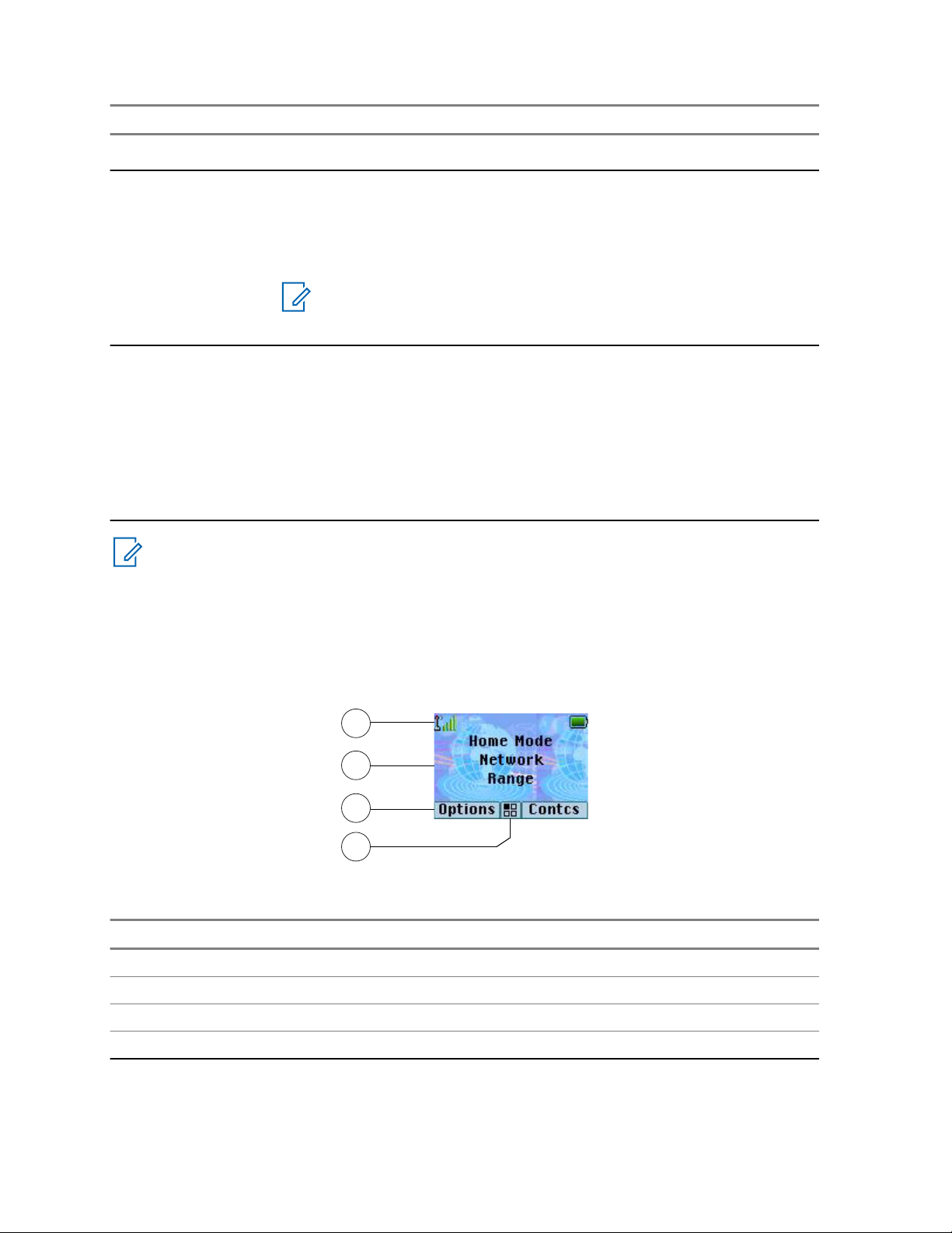
Figure 2: Default Home Screen with Icons
Table 5: Display
Annotation Description
1 Status icon area
2 Text display area
3 Soft key area
4 Menu/Context sensitive icon
28 Send Feedback
Page 29

The color of the Soft key area changes according to the mode the radio is in.
Table 6: Colors of the Soft Key Area
Color Mode or State
Light blue Normal TMO and DMO Modes
Light red Emergency Mode or Disaster Alert Call
Olive Local Site Trunking Mode
Yellow Call Out – Standby
Red Call Out – Alert
Green Call Out – Accepted
Blue Radio Messaging Service (RMS)
Gray Radio User Assignment (RUA) – Limited service
2.4.1
Configurable Idle Screen
68015000897–FC
Chapter 2: Getting Started
Your service provider can configure the information that is displayed on the idle screen below the
status icon area. The displayed information depends on the radio configuration and services
supported.
• Audio Profile Name
• BSI Registration Status
• Home Mode
• Individual Short Subscriber Identity (ISSI)
• International Talkgroup Link Alias
• Network (No Service, or Mobile Country Code (MCC) / Mobile Network Code (MNC), or Networks
Alias)
• Operational-Tactical Address (OPTA)
• Radio Status
• Range
• RMS/FMS
• RMS messages
• Scan List Alias
• Secondary Talkgroup Alias
• Talkgroup Alias
• Time and Date
Order and visibility of these items are also subject of the Configurable Idle Screen settings.
Send Feedback 29
Page 30

68015000897–FC
Chapter 2: Getting Started
2.5
Status Icons
Status icons appear when your radio is engaged in certain activities or when you have activated certain
features.
Table 7: Status Icons
Icon Description
Trunked Mode Operation
In Service
No Service
Signal Strength – The more bars, the stronger the signal.
RF Power – Indicates that High RF Power is enabled. Shows the signal strength.
The more bars, the stronger the signal.
Migration – Indicates that the radio is registered to a foreign network.
Broadcast Call – Indicates that the radio is in a Broadcast Call.
Scan – Indicates that talkgroup scanning is activated in the radio.
Packet Data or Multi-Slot Packet Data (MSPD) – The more blue sections on the
icon, the faster the data transfer. Possible status:
• Four gray sections: context activated – data idle
• One blue: Packet Data active
• Two blue: Multi-Slot Packet Data active
Direct Mode Operation
Direct Mode Call – Indicates that the radio is receiving a Direct Mode call. The more
bars, the stronger the signal.
High RF Power: idle or transmitting – Indicates High RF Power option is enabled
or
and the radio is either in idle mode or is transmitting a call.
High RF Power: receiving – Indicates High RF Power option is enabled and the radio is receiving a call.
Direct Mode – Indicates that radio is in Direct Mode (radio-to-radio communication).
DMO Gateway Communication Mode – Indicates that gateway is selected. The icon
has the following status:
• Solid – when the radio is synchronized with the gateway.
• Blinking – when the radio is not synchronized or during attachment.
• No icon – during radio-to-radio and repeater communication.
Table continued…
30 Send Feedback
Page 31

Icon Description
DMO Repeater Communication Mode – Indicates that the Repeater or GW + Rep
option in DMO Mode is selected. The icon has the following status:
• Solid – when the radio has detected the repeater (for example when the radio receives a presence signal).
• Blinking – when the radio has not detected the repeater or during attachment.
• No icon – during a radio-to-radio and gateway communication.
General Icons
All Tones Off – Indicates that:
• Volume is set to 0 (when Volume Adj. Mode is set to Common).
• Both simplex and duplex ring volume is set to 0 (when Volume Adj. Mode is set
to Individual).
Simplex Ring Muted – Indicates that simplex ring volume is set to 0 and duplex ring
volume is set to more than 0.
Duplex Ring Muted – Indicates that duplex ring volume is set to 0 and simplex ring
volume is set to more than 0.
68015000897–FC
Chapter 2: Getting Started
Low Audio – Indicates that the audio mode is changed to low.
High Audio – Indicates that the audio mode is changed to high.
Earpiece Connected – Indicates that the earpiece is connected.
Battery Strength – Shows the charge of your battery.
Battery Charging – Indicates that the battery is charging.
Emergency – Indicates that the radio is in Emergency Operation.
• Solid – Emergency Operations initiated.
• Blinking – the radio is in emergency receiving state.
Disaster Alert Call – Indicates that the radio is in Disaster Alert Call.
New Message Has Arrived – Indicates that a new message has arrived.
New Message in Inbox – Indicates that you have unread messages in your Inbox.
Unread (New) WAP Message – Indicates that new page was loaded to the browser.
Call-Out – Indicates Call-Out alert.
Call-Out Alert Arrived – Indicates a receipt of a new Call-Out message.
Call-Out Alert Unread – Indicates unread alert in the CO Box.
Table continued…
Send Feedback 31
Page 32

68015000897–FC
Chapter 2: Getting Started
Icon Description
End-to-End Encryption (E2EE)
Solid, when the E2EE is enabled:
• for the selected talkgroup,
• for the highlighted private number,
• for the manually entered private number,
• when transmitting voice in Group Calls,
• when transmitting voice in Simplex Private Calls.
Blinking, when the E2EE is enabled:
• when receiving voice in Group Calls,
• when receiving voice in Simplex Private Calls,
• during encrypted Duplex Private Calls.
Encryption Off
Blinking – Indicates that the SIM Card End-to-End Encryption is disabled in DMO
and TMO Modes.
or
SIM End-to-End Encryption (E2EE)
Solid – Indicates that the SIM Card E2EE is enabled in TMO Mode.
SIM End-to-End Encryption (E2EE)
Solid – Indicates that the SIM Card E2EE is enabled in DMO Mode. Numbers 1 and
2 point to the type of DMO Encryption keys that has been selected.
SDS End-to-End Encryption
Solid – Indicates the E2EE status of an SDS message, or the E2EE status of a message recipient address.
In High Security mode, when your radio processes only the encrypted information,
this icon is always visible in when you are in the messages menu, for example, In-
box.
Unread (New) WAP Message – Indicates that you have not entered WAP Box since
last WAP message was received.
Blinks when the priority is high.
WAP Message Icon – Displayed next to the priority WAP message in the message
list view.
WAP Message Time – Displayed next to the create date in the message list view.
WAP Message Expiration – Displayed next to the expiry date in the message list
view.
WAP Message Title Icon – Displayed next to the title along with the text in the message list view.
Keys Locked – Indicates that keys are locked.
Remote Control – Indicates that the radio is being remotely controlled and some
commands are being executed in the background. For example, when the radio is
32 Send Feedback
Page 33

Icon Description
being controlled by special SDS messages or triggered to send a GNSS location report.
2.6
Powering On the Radio
Procedure:
Press and hold On button.
Your radio performs a self-check and registration routine.
After successful registration, your radio is in service.
NOTICE: Your radio powers on without visible and audible notification if Covert Mode is
activated.
2.7
PIN Code Authentication
68015000897–FC
Chapter 2: Getting Started
If pre-set by your service provider, the radio has active PIN Code Authentication, which helps you
increase security and protect your radio against unauthorized use. The PIN code is read from the SIM
card or radio programming and cannot be changed or disabled. If you are unable to unlock the radio,
you cannot send or receive any call, nor adjust the volume level with the Rotary Knob.
You are asked to enter the PIN code each time you turn on the radio.
2.7.1
Unblocking Your Radio
Prerequisites: You blocked your radio by entering incorrect PIN code for three times (by default).
Procedure:
1 Radio displays Unit Blocked Enter PUK.
2 Enter 8–digit PUK (Personal Unblocking Key) number.
NOTICE: The PUK is an eight-digit master code provided by your service provider.
3 Enter the new PIN code twice.
2.8
Unlocking Your Radio
Your radio may be locked at power up. To unlock it after powering on, enter the code at the prompt.
Your radio enters the default home display.
NOTICE: The unlock code is originally set to 0000. Your service provider may change this
number before you receive your radio.
Send Feedback 33
Page 34

68015000897–FC
Chapter 2: Getting Started
2.9
Locking or Unlocking the Keys or Buttons
Procedure:
1 Press Menu key and Left Navigation key.
NOTICE: The Emergency button is not locked. Entering Emergency Mode unlocks all
keys.
2.10
Holding Your Radio
The radio has two microphones: a top microphone for simplex dispatcher/private calls and a bottom
microphone for duplex telephone-like calls.
The radio is also equipped with an internal speaker for high audio (located at the middle of the unit)
and an internal earpiece for low audio (located at the top of the unit). The audio can be routed either to
the speaker or the earpiece using the Audio Toggle menu (Menu → Setup → Audio → Audio
Toggle) or the assigned One-Touch Button.
NOTICE: For best performance speak directly into the top microphone.
Simplex Calls
When using high audio, hold the radio a vertical position with its top microphone 5 cm to 10 cm away
from your mouth. Speak into the top microphone. Listen through the internal speaker. Keep the
antenna at least 2.5 cm from your head and body.
Duplex Calls
When using low audio, hold your radio as you would a telephone. Speak into the bottom microphone.
Listen via the earpiece. Keep the antenna at least 2.5 cm from your head and body.
Lapel/Shoulder Use
For Group and Private Calls turn your head towards your shoulder/lapel, and speak directly into the top
microphone. Listen through the internal speaker.
Speakerphone Use
Place your radio 30 cm to 60 cm away from you. In a noisy environment, move the radio closer to you
for better transmission.
34 Send Feedback
Page 35

68015000897–FC
Chapter 2: Getting Started
2.11
High or Low Audio Toggle
The radio is able to switch from the external earpiece to the main speaker using One-Touch button and
is not required to disconnect the external earpiece or PHF.
The states of the routed audio are:
• Speaker HIGH – indicates that audio is routed to the main speaker.
• Speaker LOW – indicates that audio is routed to the earpiece or PHF earpiece, and not to the main
speaker.
2.11.1
Using High Audio
When and where to use: Placing or receiving a Phone, PABX, or Duplex Private call.
Procedure:
1 Hold your radio in a vertical position with its top microphone 5–10 cm away from your mouth.
2 Speak into the top microphone and listen through the internal speaker.
Keep the antenna at least 2.5 cm from your head and body.
2.11.2
Using Low Audio
When and where to use: Placing or receiving a Phone, PABX, or Duplex Private call.
Procedure:
1 Hold your radio as you would a telephone.
2 Speak into the bottom microphone and listen through the earpiece.
Keep the antenna at least 2.5 cm from your head and body.
2.12
During the Call
During the call, label of the right Soft key indicates the next possible change. Accessory default setup
is:
Table 8: During the Call
Soft Key Label Audio Setting
Spkr Audio goes to the main speaker (Speaker HIGH is displayed)
Erpce Audio goes to the earpiece (Speaker LOW is displayed)
PHF Audio goes to the Personal Hands Free (Speaker LOW is displayed)
2.13
Entering TMO or DMO Mode
Procedure:
1 From the home screen, press Options.
Send Feedback 35
Page 36

68015000897–FC
Chapter 2: Getting Started
2 Select Trunked Mode / Direct Mode.
2.14
Selecting Talkgroups
Follow these procedures to select talkgroup manually. If the selected talkgroups is an InterSystem
Interface (ISI) talkgroup, the radio can migrate to another talkgroup linked network, changing the
talkgroup automatically.
Procedure:
From the home screen, use one of the following methods:
• Press Left or Right Navigation key. Press Select to confirm.
• Select Options → TG by abc. Enter a talkgroup name and select the talkgroup name from the
list.
• Select Options → TG by Folder. Select a folder (for example, Favorite) and then a talkgroup
name.
NOTICE: Your radio can access up to three levels of the folder structure.
• Rotate Talkgroup Knob until the required talkgroup name is displayed.
2.14.1
Talkgroup Icons Selection
Talkgroup icons are used to indicate that a talkgroup has a special function, show the status of network
selection, and/or show the talkgroup properties. A talkgroup without an icon does not have a special
function attached to it. These icons are displayed next to the network alias on idle display and when
scrolling talkgroups in common or favorite folder lists.
Table 9: Talkgroup Icons
Icon Talkgroups in Common Folders Talkgroups in Favorite Folders
TMO Talkgroup Icons
In TMO Mode
Display when the talkgroup selected is
a SIM TMO talkgroup, and not registered to SIM network.
Single network is available.
Not displayed in common folders. In TMO Mode
In TMO Mode
Display when the talkgroup selected is
a SIM TMO talkgroup, and not registered to SIM network.
Single network is available.
In DMO Mode
Display when the talkgroup selected is
a SIM TMO talkgroup.
Single network is available.
Display when the talkgroup selected is
a normal TMO talkgroup.
Single network is available.
Table continued…
36 Send Feedback
Page 37

68015000897–FC
Chapter 2: Getting Started
Icon Talkgroups in Common Folders Talkgroups in Favorite Folders
In DMO Mode
Display when the talkgroup selected is
a normal TMO talkgroup.
Single network is available.
In TMO Mode
Display when the talkgroup selected is
an ISI or Any network TMO talkgroup.
Multiple networks are available.
In TMO Mode
Display when the talkgroup selected is
an ISI or Any network TMO talkgroup.
Multiple networks are available.
In DMO Mode
Display when the talkgroup selected is
an ISI or Any network TMO talkgroup.
Multiple networks are available.
In TMO Mode
Display when TMO ISI talkgroup selected is not assigned to home network.
Multiple networks are available.
In TMO Mode
Display when TMO ISI talkgroup selected is not assigned to home network.
Multiple networks are available.
In DMO Mode
Display when TMO ISI talkgroup selected is not assigned to home network.
Multiple networks are available.
In TMO Mode
Display when the TMO normal talkgroup selected is not assigned to the current
network.
Single network is available.
DMO Talkgroup Icons
Display when a DMO talkgroup is selected.
General Icons
Display when the radio is registered to a network that is not the home network.
NOTICE: The icon, also known as Migration icon, is only displayed on the
top of the display as a status icon.
Display when the radio is locked to a current network selection that is a single network
while the current selected ISI talkgroup or Any Net talkgroup allows multiple networks.
NOTICE: In common folders, no TMO talkgroups are shown when in DMO mode.
Send Feedback 37
Page 38

68015000897–FC
Chapter 2: Getting Started
2.15
One-Touch Buttons
The One-Touch Button feature allows you to activate a feature by a long key press of the
programmable button.
Table 10: One-Touch Button Features
Feature Description
Access Private Dialing Editor
Activation of Covert Mode Turns Covert Mode on or off.
Any Network Selects any network.
Any Talkgroup Network Selects any talkgroup network.
Call-Out Box Displays the list of call-out sessions.
Change Audio Profile Change to the specific audio profile.
Change Talkgroup Changes the talkgroup to the one programmed by your service pro-
Direct Private Number Dialing
Display Heart Rate Displays the heart rate value received from the connected GATT-
Display Operational-Tactical Address (OPTA)
DMO Pre-emptive SDS Sends the next DMO SDS or status message with elevated priority.
Flip Display Rotates the display by 180 °.
Home Only Selects only home network.
Displays the private dialing editor.
vider.
Dials a predefined private number.
based heart rate sensor.
Displays the Operational-Tactical Address (OPTA).
Home Talkgroup on Home
Network
Initiate Call-Out Fallback Sends Call-Out Fallback Alert.
LIP Report Sends a message with the location of the radio to a dedicated ad-
Lock to Current Network Selects the current network only.
Message Inbox Displays the list of messages in Inbox.
PABX Call Setup Initiates a PABX call to a predefined entry in the contact list.
Phone Call Setup Initiates a phone call to a predefined entry in the contact list.
Prefer Talkgroup Network
Shortcut
Private Call Setup Initiates a simplex or duplex private call to a predefined entry in the
Reset to Default Resets the radio to its default settings.
RMS MMI Menu Opens the RMS menu without activating RMS mode.
38 Send Feedback
Selects only home network and home talkgroup network.
dress.
Displays the Prefer Talkgroup Network menu.
contact list or to the last group call originator.
Table continued…
Page 39

Feature Description
RUI Logon or Logoff Asks for the credential or logs off the radio.
68015000897–FC
Chapter 2: Getting Started
Scan for Bluetooth Devices
Select Talkgroup Network
Activates scanning for Bluetooth devices once OTB assigned to the
Add Bluetooth Device function is pressed.
Displays the Select Talkgroup Network menu.
Shortcut
Selecting Audio Profiles Scrolls through all available audio profiles.
Send Double Push PTT
Sends the D-PTT tone to the currently used talkgroup.
Tone (D-PTT)
Send Predefined Template
Sends a predefined message to a dedicated address.
(PDT)
Send Status Message Sends a dedicated status message to a dedicated address.
Send User-Defined Tem-
Sends a user-defined message to a dedicated address.
plate (UDT)
Switch to Previously Selected Talkgroup
Changes the talkgroup of the radio to the previously selected talkgroup (DMO or TMO).
Timed Talkgroup Change Makes a predefined talkgroup the selected talkgroup for a specified
amount of time. While using the predefined talkgroup, the second
press of the One-Touch Button results in:
• the radio returning to the previously selected talkgroup,
• the radio restarting the predefined time, or
• no action on the radio, depending on the configuration
After the timer expires, the radio returns to the previously selected
talkgroup.
Toggle Backlight Toggles the backlight on or off.
Toggle Backlight Intensity Regulates the backlight intensity.
Toggle Bluetooth GATT
Toggles Bluetooth GATT Sensor MMI Alerts on or off.
Sensor MMI Alerts
Toggle BSI Encryption En-
Enables or disables BSI encryption.
abled or Disabled
Toggle Call Forwarding Toggles Call Forwarding on or off.
Toggle DMO or TMO Toggles between TMO and DMO modes.
Toggle Extra Zoom Turns Extra Zoom on or off.
Toggle Hi or Low Audio Toggles audio high or low.
Toggle Howling Suppres-
Enables or disables Howling Suppression.
sion
Toggle RF Power Class Toggles the RF Power Class between High and Normal.
Toggle Rotary Knob Lock Locks or unlocks the Rotary Switches.
Toggle Screen Saver Activates or deactivates the Screen Saver feature.
Toggle Talkgroup Scan Turns the Talkgroup Scan feature in TMO Mode on or off.
Table continued…
Send Feedback 39
Page 40

68015000897–FC
Chapter 2: Getting Started
Feature Description
Toggle Transmit Inhibit
Turns Transmit Inhibit Mode on or off.
Mode (TXI)
Turn Repeater Mode On
Turns Repeater Mode on or off.
or Off
Unassigned The radio displays Unassigned Button when no feature assigned
to this button.
Universal Time Display Displays universal time on the home screen.
Volume Down Press to decrease the volume by one level. Press and hold to contin-
uously decrease the volume to its minimum level.
Volume Up Press to increase the volume by one level. Press and hold to contin-
uously increase the volume to its maximum level.
40 Send Feedback
Page 41
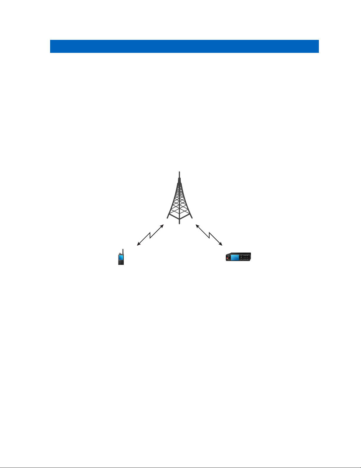
68015000897–FC
Modes
Chapter 3
Modes
This chapter contains information on available modes that the radio can operate in.
3.1
Trunked Mode Operation
Trunked Mode Operation (TMO) requires the switching and management infrastructure.
This operation mode enables various voice and data communication types, such as group calls and
short data service messages, as well as access to the infrastructure-related features such as packet
data.
Figure 3: Trunked Mode Operation
3.1.1
Entering TMO Mode
Procedure:
1 Do one of the following:
• From the home screen, press Options.
• From the home screen, press the Menu key. Select Networks.
2 Select Trunked Mode.
3.1.2
Making Group Calls in TMO
The Group Call is received by all members of the selected group who have their units turned on and
are connected through the network.
Procedure:
1 Press and hold the PTT button.
Send Feedback 41
Page 42

68015000897–FC
Chapter 3: Modes
2 Wait for the Talk Permit tone (if configured) and then speak into the microphone. Release the
PTT button to listen.
3.1.3
Receiving Group Calls in Idle
Procedure:
1 The radio receives a Group Call.
NOTICE: The incoming Group Call is signalled by a Receiving Group Call tone.
2 To respond, press and hold the PTT button.
3.1.4
Receiving Group Calls during Ongoing Group Calls
While in active Group Call, your radio receives a Group Call with a higher priority.
One of the following occurs:
• Your radio is forced to end the current group call and automatically join the incoming one.
• Your radio displays incoming group call screen with options:
- Join – ends current Group Call and starts the incoming one.
- End – cancels the incoming Group Call.
3.1.5
Dynamic Group Number Assignment (DGNA)
DGNA allows the network operator to dynamically manage talkgroups on your radio over the air
interface. Using DGNA, the network operator can:
• Add talkgroups.
• Attach or select newly added talkgroups.
• Delete talkgroups.
• Modify parameters of existing talkgroups.
All the above operations are performed by transmitting data to your radio.
3.1.5.1
DGNA Reception
When a DGNA message is received, your radio plays a tone and displays a message Talkgroup
list updated. If enabled by your service provider, your radio displays all added and deleted
talkgroup list.
When your service provider deletes (de-assigns) the currently selected talkgroup, depending on the
settings, the radio can perform one of the following actions:
• Enter the “No Group” state – the radio does not attach to any talkgroup automatically.
• Attach to the last selected TMO talkgroup. If the last selected TMO talkgroup is not available (it was
deleted), the radio enters the “No Group” state.
• Attach to a default talkgroup configured by your service provider. If the default talkgroup is not
available (it was deleted), the radio enters the “No Group” state.
42 Send Feedback
Page 43

68015000897–FC
Chapter 3: Modes
At each talkgroup change, an appropriate notification is shown on the display.
If the DGNA message is received to delete all talkgroups, your radio displays All Talkgroups
Deleted. To exit the DGNA display, you can use the Back Soft key or the End key.
3.1.5.2
DGNA Auto Select Group
If the DGNA Auto Select is configured, whenever your radio receives a DGNA, it switches to the added
talkgroup.
3.1.5.3
DGNA Auto Reselect Group
If the DGNA Auto Reselect is configured, whenever a talkgroup assigned by the network operator via
DGNA is deassigned without the user action, the radio returns to the previously selected group.
3.1.5.4
Viewing DGNA Talkgroups
Prerequisites: Your radio receives the DGNA message.
Procedure:
1 To view the added talkgroups details press View.
2 Scroll through the list to select required talkgroup.
3 To select the DGNA group, press Attach.
3.1.6
Broadcast Call
Broadcast Group Call (also called Site Wide Call) is a high-priority group call from the console operator
(or dispatcher) to all users located at one or more sites. The radios are configured to monitor a
Broadcast Call, but you cannot talk back. The call can be received as a normal Broadcast Call or an
Emergency Broadcast Call. The Broadcast Call preempts an ongoing Group Call that has the same or
lower call priority.
3.1.6.1
Broadcast Calls Initiated by Users
This feature allows you to make a Broadcast Call from the radio that is initiated on the predefined
talkgroup. Your service provider predefines the alias and the priority of the Broadcast Call.
NOTICE: If the type of the encryption is defined by the SIM Card, the Broadcast Call is always
clear. Otherwise if the radio uses other encryption service the type of the encryption used for
that Call is up to the encryption settings of that service.
This feature is not supported on the Dimetra infrastructure.
3.1.6.2
Initializing Broadcast Calls
Procedure:
1 From the home screen, press the Menu key.
Send Feedback 43
Page 44

68015000897–FC
Chapter 3: Modes
2 Select Services → Broadcast.
Your radio displays the predefined alias and the Broadcast Call icon.
3 To start the call press the PTT button.
3.1.7
Phone and Private Automatic Branch Exchange (PABX) Calls
Phone Call allows you to call a landline telephone number or a cellular mobile phone number. Private
Automatic Branch Exchange (PABX) Call allows you to call local (office) extension numbers.
3.1.8
Assistance Call
This feature allows you make a private call to ask for assistance during normal and non-critical
situations.
NOTICE: Your service provider can configure the number, priority, and the type of the call
(simplex or duplex).
3.1.9
Call Modification
Call Modification is a feature that allows your service provider to modify the call to optimize it and
adjust to a current situation.
Modification can cover:
• Call priority - modified during call setup.
• Call type - modified during call setup.
• Call encryption - modified during an ongoing call, but not in the transmission phase.
When the call is modified, your radio displays Call Modified message.
When a recently modified call requires the PTT button to transmit, your radio displays Call
Modified Use PTT.
All modifications are made by your service provider and the radio only follows them. You have no
influence on ongoing call modifications.
When call priority is changed to emergency:
• The display indicates that an Emergency Group Call has been received.
• The radio plays a special audio alert.
NOTICE: If a Group Call is modified into an Emergency Group Call, no emergency-related
features are triggered.
If the radio cannot follow a call modification requested by the service provider, due to its settings, the
radio rejects it and displays Service Not Available message.
3.2
Local Site Trunking
This mode is also called as Fallback Mode and it allows more than one radio from the same site to
communicate when the link between the site and the network central controller fails. Entering and
exiting Local Site Trunking (that is, returning to System Wide Services) is done automatically. In this
mode, some services are unavailable.
44 Send Feedback
Page 45

68015000897–FC
Chapter 3: Modes
NOTICE: Your service provider can disable this mode.
3.2.1
Entering Local Site Trunking
When your radio receives a Local Site Trunking indication from the system, the following occurs:
• Your radio plays an Entering Local Site Trunking tone.
• Display shows the Local Area Service message.
• Display icons and soft keys turn olive.
NOTICE: Noticeable only on the color display.
• Any call in progress is dropped upon entering Local Site Trunking Mode.
If configured by your service provider, this message/alert is periodically repeated to remind you that
your radio is still operating in Local Site Trunking Mode. The following features are available:
• Registration
• Attachment
• Group Call
• Emergency Call
• Emergency Alarm
3.2.2
Exiting Local Site Trunking
When the link with the central network controller is reestablished, your radio exits Local Site Trunking,
and the following occurs:
• Your radio plays an Exiting Local Site Trunking tone.
• Any call in progress during Local Site Trunking is dropped.
• Display icons and soft keys turn blue.
3.3
Direct Mode Operation
Direct Mode Operation (DMO) is a mode of simplex operation where radios communicate directly
without the need of a network.
Send Feedback 45
Page 46
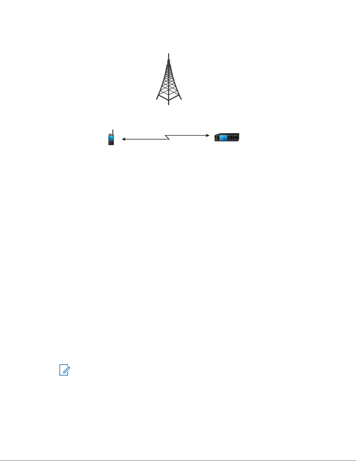
68015000897–FC
Chapter 3: Modes
Figure 4: Direct Mode Operation
3.3.1
Entering DMO Mode
Procedure:
To enter the DMO Mode:
• From the home screen, press the Menu key. Select Networks → Direct Mode.
• From the home screen, press the Menu key. Select Options → Direct Mode.
3.3.2
Making Group Calls in DMO
The Group Call is received by all members of the selected group who have their units turned on and
are in range.
Procedure:
1 Press and hold the PTT button.
2 Wait for the Talk Permit tone (if configured) and then speak into the microphone. Release the
PTT button to listen.
3.3.3
Receiving Group Calls in Idle
Procedure:
1 The radio receives a Group Call.
NOTICE: The incoming Group Call is signalled by a Receiving Group Call tone.
2 To respond, press and hold the PTT button.
46 Send Feedback
Page 47

68015000897–FC
Chapter 3: Modes
3.3.4
Selecting DMO Communications Options
When and where to use: Helps to communicate with other radio users on the same talkgroup through
the Gateway or Repeater.
Procedure:
1 From the home screen, press Options.
2 Press Config.
3 Select one of the following:
• MS - MS – Your radio can communicate only with other radios within its range.
• Gateway – Your radio uses a gateway to communicate with the infrastructure.
• Automatic – Your radio uses the first available gateway for that talkgroup.
• Specific – Your radio uses only the Gateway with the specified Gateway address for that
talkgroup. If your radio displays Selected Gateway: None, press Edit to enter the
current gateway address.
• Repeater – Uses the first available repeater for that talkgroup.
• GW + Rep – Uses the first available gateway or repeater for that talkgroup.
• Automatic – Uses the first available gateway for that talkgroup.
• Specific – Uses only the Gateway with the specified Gateway address for that talkgroup.
If your radio displays Selected Gateway: None, press Edit to enter the current
Gateway address.
NOTICE:
When the Gateway and the Repeater cannot be communicated even though a
talkgroup to use them is configured, the radio attempts the direct MS-MS
communication.
When your radio detects the appropriate Gateway and/or the Repeater, the Gateway and/or Repeater
icons turns solid, respectively.
3.3.5
DMO Private Priority Call
The service provider may assign Pre-emptive Priority to outgoing DMO Private Calls. If this is the case,
DMO Private Calls from this radio preempt any ongoing calls (with the exception of emergency calls or
ongoing Pre-emptive Priority Private Calls) on the receiving radio, which then displays Call-
preempted.
3.3.6
Talkgroup for Individual Calls
Talkgroup for Individual Calls is a talkgroup that operates on a separate frequency allocated for
individual (private) calls only. Using this talkgroup optimizes frequency resources and helps not to
block other talkgroups. The only supported call types are: private calls and emergency calls (both
private and group). Use this talkgroup each time you need to make a private call.
When you select a Talkgroup for Individual Calls, your radio is not able to receive or initiate any group
or broadcast calls with priority lower than Emergency.
When you have selected a Talkgroup for Individual Calls and press the PTT button to start a Group
Call, the radio:
Send Feedback 47
Page 48

DMO
TMO
Private Call
68015000897–FC
Chapter 3: Modes
• Rejects the call
• Plays a tone
• Displays the Individual Calls Only message
3.3.7
Network Monitor
This feature allows the radio to monitor for TMO individual calls while maintaining DMO services.
When Network Monitor is active, the radio receives direct calls addressed to the selected DMO
talkgroup, private DMO calls, SDS messages, but also private TMO calls.
The group calls, private calls, and SDS messages initiated are configured in DMO. Only responses to
private TMO calls are sent in TMO.
3.3.7.1
Enabling Network Monitor
Prerequisites: Ensure your service provider enabled the Network Monitor feature.
Procedure:
1 From the home screen, press Options.
2 Press Network Monitor.
3.3.8
Communication through Repeaters
Radios that are out of range and cannot communicate directly one with another in Direct Mode
Operation (DMO) can do it through the repeater. The repeater is a radio that repeats all communication
on a chosen channel, and as a result increases radios DMO range.
48 Send Feedback
Page 49
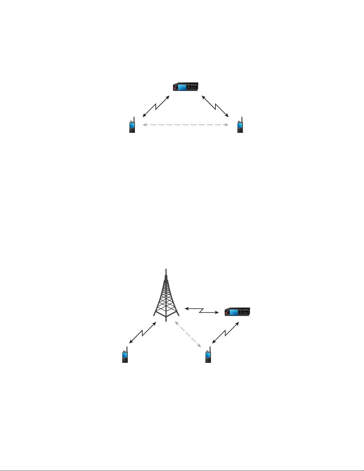
DMODMO
DMO
TMO
TMO
68015000897–FC
Chapter 3: Modes
Figure 5: Communication through Repeaters
When the radio connects to a repeater, it plays a tone, displays the Repeater available message,
and shows an appropriate icon. When the radio loses connection with the repeater, it plays a tone,
displays the Repeater not available message, and the repeater icon is blinking.
3.3.9
Communication through Gateways
Gateway provides connectivity between radios operating in Direct Mode Operation (DMO) and the
TETRA network, so that the DMO radios can communicate with the Trunked Mode Operation (TMO)
radios.
Figure 6: Communication through Gateways
When the radio connects to a gateway, it plays a tone, displays the Gateway available message,
and shows an appropriate icon. When the radio loses connection with the gateway, it plays a tone,
displays the Gateway not available message, and the gateway icon is blinking.
Send Feedback 49
Page 50

68015000897–FC
Chapter 3: Modes
3.3.10
Gateway and Repeater Synchronization
To communicate via gateways or repeaters, the radio requires synchronization with a gateway or a
repeater.
A gateway or a repeater sends presence signals to radios. If a radio receives presence signals, it stays
synchronized with the gateway or the repeater which sends the signals. If a radio fails to receive a
presence signal it does not immediately lose synchronization. The radio waits for another successful
presence for a time defined by your service provider. This function ensures that communications are
not dropped due to temporary reception issues.
If a gateway or a repeater is unavailable or the radio is not synchronized with a gateway or a repeater,
depending on the setup configured by your service provider, the following scenarios apply:
• The radio falls back to Direct Mode Operation (DMO).
• After pressing the PTT button, a prompt appears warning that the second press overrides the
gateway or repeater operation mode.
• No direct DMO communications are permitted.
In the second scenario, while the radio receives individual calls and group calls, and replying to
individual calls is possible, replying to group calls is not possible.
3.4
Transmit Inhibit Mode
The Transmit Inhibit (TXI) Mode is a mode in which the radio sends no radio transmissions. Activate
this mode in RF sensitive areas, for example hospitals, airplanes, where safety can be jeopardized due
to transmission radiation.
To activate, select Menu → Networks → TXI Mode → Activate.
In this mode, the radio does not transmit under any circumstances except for the Emergency Calls. All
the functions and keys which cause transmission, for example registration to the network, changing
talkgroup or folder, sending SDS messages, or pressing the PTT button are disabled. Any transmission
trial causes the radio to display Not Allowed In TXI Mode notification and to play a tone.
Your radio can still receive:
• Group calls.
• Messages - stored in the Inbox.
• Private call attempts - stored in the Missed Calls list, without the option to respond.
When no danger to safety exists anymore, for example, when you leave the RF sensitive area, you can
deactivate the TXI Mode and the radio returns to standard operation.
You can deactivate the mode by selecting Menu → Networks → TXI Mode → Deactivate, pressing
One-Touch Button, or implicitly when initiating an Emergency Call.
NOTICE: RF Transmissions from the radio are prevented under the following conditions:
• TXI Mode is activated.
• Battery is removed.
• The radio is turned off.
On entering or exiting the TXI mode, when the radio is camped on a cell, it sends a specially
designated Short Data Service (SDS) status message. This SDS message indicates to the SwMI that
the radio is entering or exiting TXI mode.
Mobility procedures that do not require the radio to send an uplink transmission are performed except
for cell reselection.
50 Send Feedback
Page 51

DMODMO
68015000897–FC
Chapter 3: Modes
In TXI mode, the radio joins group calls for any group that the radio is monitoring, but the transmitting
on that call is still prohibited.
The radio also displays any incoming SDS messages to the user. The missed call feature is active in
the TXI mode and allows checking what calls were missed. However, the radio attempts to prevent call
setup retransmission from being recorded as separate calls.
If you initiate an emergency call, the radio immediately leaves TXI mode and attempts to start the
emergency call if the radio is in service.
If the radio is turned off in the TXI mode, on turning on, the radio asks whether to exit the TXI mode. If
you choose No, the radio turns off.
3.5
Repeater Mode
NOTICE: This feature is a paid feature.
The Repeater Mode provides repeater connectivity between radios operating in the DMO Mode.
Figure 7: Repeater Mode Operation
A DMO repeater is used to extend the DMO range by retransmitting received information from one
radio to another. It retransmits group calls, private calls and data on a given frequency. In the diagram
above the radio in the middle is a repeater.
The repeater sends presence signal periodically on a free channel to allow other radios to synchronize
on a given frequency.
Only the radios on the same talkgroup can communicate with each other through the repeater.
The Repeater Mode is activated by selecting Menu → Networks → Repeater Mode.
Send Feedback 51
Page 52

This page intentionally left blank.
Page 53

68015000897–FC
Main Menu
Chapter 4
Main Menu
This chapter contains information on items in the main menu.
You can enter the menu items during a call. If not programmed otherwise by your service provider the
radio exits the menu, when a new call starts.
IMPORTANT: Some menu items are model-specific and may not be activated or available on
your radio.
4.1
Scrolling through the Menu
Procedure:
1 From the home screen, press the Menu key.
2 Scroll to the required item by pressing Navigation keys. Press the Soft key assigned as Select
or Right Navigation key to select.
If the menu item contains a further set of menu items, repeat step 2.
4.2
Menu Icons
The following icons make it easy to identify the menu items at first glance.
Table 11: Menu Icons
Menu Icon Description
Main Menu Items/Context Sensitive Menu
It is assigned to Menu when the main menu items / context-sensitive menu are
active.
Messages
• Send status messages,
• Send text messages (free text or according to user defined or predefined
templates),
• Received messages in Inbox.
Contacts
Add, search, edit, or erase entries in the contact list.
Browser
Starts the WAP browser.
Security
Lets you turn on/off and verify security features, and change passwords.
Table continued…
Send Feedback 53
Page 54

68015000897–FC
Chapter 4: Main Menu
Menu Icon Description
Setup
Allows you to customize your radio.
Group Setup
Contains additional menu items for Scanning Talkgroups features.
My Info
Displays information about your radio and its numbers.
Recent Calls
Contains a list of recent calls.
RUI
Allows you to log in and log out of the radio.
Networks
Allows you to select a network.
Packet Data
Allows you to send data from your radio to other devices.
Services
Allows you to manage Broadcast, Assistance, and Disaster Calls.
4.3
Messages
This feature allows you to send and receive text messages. A message can contain up to 1000
characters, depending on your service provider settings.
Pressing the PTT button when a message is highlighted can cause one of the following actions,
depending on your service provider settings:
• The radio ignores the PTT button request.
• The radio starts a Private Call with the message sender.
• The radio starts a Group Call on a currently selected talkgroup.
See Writing Text on page 112 for details on writing a text message.
4.3.1
New Message
This menu item allows you to create a new message.
NOTICE: While editing a text, Status Icons change their appearance and only four of them are
displayed: Tower, Signal Strength, Emergency, and Battery.
54 Send Feedback
Page 55

4.3.1.1
Sending Messages to Private/Phone
Procedure:
1 From the home screen, press the Menu key.
2 Select Messages → New Message.
3 Enter your message and press Send.
4 If needed, select Private/Phone.
5 Enter recipient number or press abc to choose it from your contacts.
NOTICE:
For Private target selection, you can enter either Individual Short Subscriber Identity
(ISSI), Individual TETRA Subscriber Identity (ITSI), or Group Short Subscriber Identity
(GSSI) of the recipient.
ISSI/ITSI – a unique, individual ID assigned for each radio.
GSSI – in Dimetra called Group ID or Talkgroup ID.
6 Press Send, or Send key, or the PTT button.
68015000897–FC
Chapter 4: Main Menu
4.3.1.2
Sending Messages to Groups
Procedure:
1 From the home screen, press the Menu key.
2 Select Messages → New Message.
3 Type your message and press Send.
4 If needed, select Group.
5 Select a group to send the message.
4.3.1.3
Sending Store and Forward Messages
Prerequisites: Your service provider enables the Store and Forward feature.
Procedure:
1 From the home screen, press the Menu key.
2 Select Messages → New Message.
3 Press Menu key and select Message Setup → On/Offline users.
4 Enter your message and press Send.
5 If asked for the Target selection, select one of the following:
• Private – enter the private number or press abc to choose the destination number from the
contact list.
• Phone – enter the phone number or press abc to choose the destination number from the
contact list.
NOTICE: Your service provider can enable to send a Store and Forward message to a
talkgroup.
6 Select Send, or press Send key or PTT button.
Send Feedback 55
Page 56

68015000897–FC
Chapter 4: Main Menu
4.3.1.4
Delivery Report
Delivery Report is an acknowledgment that the radio can request upon sending a message to an
individual recipient. You can define what type of Delivery Report your radio requests, or turn on/off this
feature.
If the Delivery Report is received shortly after the message was sent, the radio:
• Displays a pop-up with one of the following messages:
- Message Sent – if no Delivery Report is requested (and when a Store and Forward message
has been received at the Store and Forward server).
- Message Delivered – if the Delivery Report is requested and the message has been
received by the target radio.
- Message Read – if the Consumed Delivery Report is requested and the message is opened on
the target radio.
- Message Failed – if the Delivery Report is requested and the message has not been received
by the target radio within a defined time period.
• Saves the Delivery Report in Outbox along with a copy of the message.
If the Delivery Report is received after a longer period of time, the radio:
• Saves the Delivery Report in Outbox along with a copy of the message.
• If Delivery Report Notifications functionality is configured by your service provider, the radio also:
- Temporarily saves a Delivery Report message in Inbox. The notification disappears after it is
read.
- Displays New Message icon.
- Displays New Delivery Status notification screen (if possible).
4.3.1.4.1
Viewing Delivery Reports
Procedure:
1 From the home screen, press the Menu key.
2 Select Messages → Inbox.
3 Find a required message and select Read.
4 Press Menu key.
5 Select Delivery Status.
4.3.1.4.2
Configuring Delivery Reports
Prerequisites: Your service provider enabled the delivery report configuration.
Procedure:
1 From the home screen, press the Menu key.
2 Select Messages → New Message.
3 Press Menu key and select Delivery Report.
4 Select one of the following:
• None – the radio does not request any delivery report.
56 Send Feedback
Page 57

68015000897–FC
Chapter 4: Main Menu
• Received – the radio requests reports on your messages that were received.
• Consumed – the radio requests reports on your messages that were read.
• Both – the radio requests reports on your messages that were received and read.
4.3.2
Inbox
The Inbox folder contains up to 100 new or old incoming messages, depending on the length of the
messages.
Table 12: Inbox Icons
Icon Description
Unread (New) Message
Read (Old) Message
Unread (New) Protected Message
Read (Old) Protected Message
Message Protected
Sender Information in Message View – name or number
Time and Date Stamp in Message View – arrival time and date
Delivery Status Received – delivery status for Store and Forward messages
Messages sub-menu indicates the number of the messages. If the indication is for example 2/4, it
means that two unread and four read messages are in the Inbox.
4.3.2.1
Entering the Inbox
Procedure:
1 From the home screen, press the Menu key.
2 Select Messages → Inbox.
NOTICE: The status (if any) of the list is displayed for a few seconds:
• No New or Old Messages – The screen returns to the previous display within a
few seconds.
• Inbox Full – Select OK.
Send Feedback 57
Page 58

68015000897–FC
Chapter 4: Main Menu
4.3.2.2
Receiving New Messages
Prerequisites: Your radio displays a New Message icon, an animation, and plays a New Mail
Received tone.
Procedure:
Select one of the following:
• Read – opens the entire message.
• Back – dismisses the message. You can access the message later from the Inbox.
4.3.2.3
Using Submenus in the Inbox and the Outbox
Procedure:
1 From the home screen, press the Menu key.
2 Select Messages → Inbox or Outbox.
3 Highlight the required message and press Menu key.
4 Do one of the following:
• Store – Saves a message as a template. Change the default template name and press OK.
• Delete – Deletes the selected message. Press Yes to confirm.
• Delete All – Deletes all the messages in the Inbox or Outbox. Press Yes to confirm.
• Reply (only for Inbox) – Invokes the edit screen with the old message as default text and the
message originator as a recipient. After editing, press Send, the PTT button, or the Send key
to send.
• Resend (only for Outbox) – Invokes the edit screen with previously entered text with the
same recipient. After editing, press Send, the PTT button, or the Send key to send.
• Forward – Invokes the edit screen with the old message to send it to a different participant.
After editing, press Send, the PTT button, or Send key to send.
• Refresh – Re-orders the message list and displays the new messages.
• Delivery Status (only for Outbox) – Shows the date and time of the message when it is
sent, delivered, read, and expired; was not delivered, expired was not read, or failed
unknown.
• Protect – Protects the message from being deleted or overwritten.
• Unprotect – Remove the protection of the message.
4.3.2.4
Embedded Number
This feature allows you to call a number from a message or to start a group call with the message
sender talkgroup.
4.3.2.5
Storing Numbers from Messages
Prerequisites: Embedded Number feature is enabled by your service provider.
58 Send Feedback
Page 59

68015000897–FC
Chapter 4: Main Menu
When and where to use: You can save the number of the sender or embedded number from the
message to a new or existing contact.
Procedure:
1 From the home screen, press the Menu key.
2 Select Messages → Inbox.
3 Highlight the required message and select Read.
4 Press the PTT button.
5 Radio displays a list of the numbers (including the senders number).
6 Highlight the required number and press Store.
7 Highlight required contact and press View.
NOTICE: To store a number for a new contact, select [New Contact] and fill out the
required fields. Press Done to save it.
8 Select Edit.
9 Choose the Type of the new number and press Done.
4.3.2.6
Calling Numbers in Messages
Prerequisites: Embedded Number feature is enabled by your service provider.
When and where to use: You can return a voice call to the sender of a message or to any number
that is embedded in the message text.
Procedure:
1 From the home screen, press the Menu key.
2 Select Messages → Inbox.
3 Highlight the required message and select Read.
4 Press the PTT button.
5 Radio displays a list of the numbers (including the senders number).
6 To call, highlight to the required number and press the PTT button or the Send key.
7 Select Ctype to choose the type of call (Private, Phone, or PABX).
8 Press the PTT button or the Send key.
4.3.2.7
Making Group Calls on the Talkgroup of the Message Sender
Prerequisites: Embedded Number feature is enabled by your service provider.
Procedure:
1 From the home screen, press the Menu key.
2 Select Messages → Inbox.
3 Highlight the required message and press the PTT button.
Send Feedback 59
Page 60

68015000897–FC
Chapter 4: Main Menu
4.3.2.8
Immediate Message
NOTICE: This feature is a paid feature.
When the new immediate message is received, radio plays the New Mail Received tone and displays
the content overlapping your previous screen. All immediate messages are stored in the Inbox. If the
radio is in PIN Lock state, immediate message is displayed after correct PIN is entered.
The message stays on the screen until you press the End/Home key.
4.3.3
Outbox
Outbox stores up to 100 sent messages arranged chronologically with the last sent message at the top
of the list.
Table 13: Outbox Icons
Icon Description
Delivery in Progress
Delivery Accomplished
Delivery Failed
Successful Outgoing Message
Failed Outgoing Message
Protected Message Delivery in Progress
Protected Message Delivery Accomplished
Protected Message Delivery Failed
Successful Outgoing Protected Message
Failed Outgoing Protected Message
4.3.4
Call-Out (CO) Box
CO Box contains incoming and outgoing Call-Out messages. Clicking Select on a Call-Out message
headline displays more detailed information on the item.
When the radio is in normal mode, you are able to browse through all messages in the CO Box.
However, if the radio is in the Call-Out mode, you can only browse through the information regarding
the currently ongoing Call-Out message.
60 Send Feedback
Page 61

4.3.4.1
Call-Out Icons
Table 14: Call-Out Icons
Icon Description
Read (Old) Call-Out Message in Inbox
Unread (New) Call-Out Message in Inbox
Read (Old) Protected Call-Out Message in Inbox
Unread (New) Protected Call-Out Message in Inbox
Read (Old) Call-Out Message in Outbox
Read (Old) Protected Call-Out Message in Outbox
68015000897–FC
Chapter 4: Main Menu
4.3.5
Radio Messenging System (RMS) Box
RMS Box stores all incoming and outgoing Radio Messaging System (RMS) messages, both Status
messages and Free Text messages.
4.3.6
Wireless Application Protocol (WAP) Box
Each WAP Push message can be loaded immediately or stored as a message in WAP Box. Then it
can be accessed by pressing Menu → Messages → WAP Box. All the WAP Push messages are
passed to the browser.
4.3.7
Templates
Templates box stores user-defined message templates. Each of the Inbox and Outbox message can
be stored as a template. Each template name and text can be edited afterwards.
4.3.7.1
Sending User-Defined Templates
Procedure:
1 From the home screen, press the Menu key.
2 Select Messages → Templates.
3 Highlight the required template name and press Send.
4 Do one of the following:
• Enter the number or press abc to select the name from your contact list. Press Send.
• Select required talkgroup from the TalkGroup List.
Send Feedback 61
Page 62

68015000897–FC
Chapter 4: Main Menu
4.3.7.2
Managing User-Defined Templates
Procedure:
1 From the home screen, press the Menu key.
2 Select Messages → Templates.
3 Highlight the required template and press Menu.
4 Select one of the following:
• View – Displays template text.
• Delete – Deletes the template.
• Edit Text – Opens edit screen with the template text. Edit the text and press Menu. Select
Save Changes to save edited template, or Store to save the edited template as a new one.
• Edit Name – Opens edit screen with the template name. Press Ok to save the template.
4.3.8
Predefined Templates
Predefined message templates are programmed into your radio. You are allowed to perform limited
edit operations of the predefined template. You can send it, but you are not able to store the edited
template or erase it from the predefined template list.
4.3.8.1
Viewing Predefined Templates
Procedure:
1 From the home screen, press the Menu key.
2 Select Messages → Predefined.
3 Highlight the required template and press Menu key.
4 Select View.
4.3.8.2
Sending Predefined Templates
Procedure:
1 From the home screen, press the Menu key.
2 Select Messages → Predefined.
3 Highlight the required template and press Send, the PTT button, or the Send key.
NOTICE: You can edit the predefined template before you send it. Press the Menu key
and select Edit. Edit screen opens with the template text. You are only allowed to
replace the existing text.
4.3.9
Status Messages
The radio allows you to send two types of status messages: statuses and targeted statuses. Your
service provider determines which type is enabled on the radio.
62 Send Feedback
Page 63

68015000897–FC
Chapter 4: Main Menu
Statuses can be sent either to a selected talkgroup or to a private number programmed by your service
provider. Targeted statuses can be sent to any talkgroup defined for the radio or to any private number
(from the contact list or entered manually).
4.3.9.1
Viewing a Status Message Number
Procedure:
1 From the home screen, press the Menu key.
2 Select Messages → Send Status.
3 Press the Menu key and select View.
4.3.9.2
Sending Status Messages
This procedure allows you to send status messages to either a selected talkgroup or a programmed
private number. Only one option can be enabled at a time.
Prerequisites:
• If sending statuses to talkgroups is enabled: switch to the talkgroup to which you want to send a
status message.
• If sending statuses to private numbers is enabled: no action is needed, the private number is set up
by your service provider
Procedure:
1 From the home screen, press the Menu key.
2 Select Messages → Send Status.
3 Highlight the required status message and press Select, the PTT button, or the Send key.
4.3.9.3
Targeted Status Messages
This feature enables sending status messages to user selectable addresses. By default, targeted
status messages can be sent to private or talkgroup addresses. Your service provider may restrict valid
addresses to numbers stored in Contacts.
NOTICE: This feature is not supported on Dimetra networks.
4.3.9.3.1
Sending Targeted Status Messages
Procedure:
1 From the home screen, press the Menu key.
2 Select Messages → Send Status.
3 Highlight the required status message and press Select, the PTT button, or the Send key.
4 Do one of the following:
• Enter the number or press abc to select the name from your contact list. Press Send.
• Select required talkgroup from the TalkGroup List.
The display shows one of the following delivery reports:
Send Feedback 63
Page 64

68015000897–FC
Chapter 4: Main Menu
• Status Sent.
• Status Failed.
4.3.10
Sending an RMS Status
Prerequisites: This feature is only available when enabled by your service provider. See Radio
Messaging System (RMS) on page 109 for details.
Procedure:
1 Do one of the following:
• From the home screen, press Menu → Messages → Send RMS/FMS.
• Press and hold the One Touch Button configured to display the Send RMS/FMS menu.
NOTICE: The navigation through the radio menu is only available if your service provider
enabled the Send RMS/FMS menu item. However, your service provider can configure a
One Touch Button to display the Send RMS/FMS menu even if the navigation is not
possible.
If the Send RMS/FMS menu item is disabled, and no One Touch Button is configured to
display the Send RMS/FMS menu, then the radio can only receive RMS messages but
cannot send them.
2 Scroll to the required RMS status.
4.3.11
Additional Address
The Additional Address feature allows the radio to send RMS messages, and Local Information
Protocol (LIP) reports to additionally defined recipients.
The default addresses where the radio sends RMS messages and LIP reports are defined by your
service provider. If an Additional Address is selected and enabled, RMS messages and LIP reports are
also sent to the recipient defined in the Additional Address.
You can create, edit, and delete Additional Addresses using the radio menu. If an Additional Address is
configured by your service provider, the service provider can disable edition and deletion of the
address using the radio menu.
You can define up to 30 Additional Addresses.
4.3.11.1
Enabling or Disabling Additional Address
Procedure:
1 From the home screen, press the Menu key.
2 Select Messages → Additional Address → Enable.
3 Select one of the following:
• On – to activate the feature
• Off – to deactivate the feature
64 Send Feedback
Page 65

68015000897–FC
Chapter 4: Main Menu
4.3.11.2
Selecting Additional Address
Procedure:
1 From the home screen, press the Menu key.
2 Select Messages → Additional Address → Select Address.
Select Address display appears with an available list of aliases.
3 Scroll through the list to highlight your alias and press Select.
4.3.11.3
Viewing Additional Address
Procedure:
1 From the home screen, press the Menu key.
2 Select Messages → Additional Address → Select Address.
3 Scroll to select the alias of the Additional Address you wish view.
4 Press the Menu key.
5 Select one of the following:
• Edit (for User Defined Additional Address alias)
• View (for Pre-defined Additional Address alias)
The display shows the Alias, the ISSI/ITSI/GSSI and the Status of the address (Pre-Defined or User
Definded).
4.3.11.4
Entering New Additional Address
Procedure:
1 From the home screen, press the Menu key.
2 Select Messages → Additional Address → Select Address.
3 Select [New Address]
4 Press Change key.
5 Enter new values of the Alias and ISSI/ITSI/GSSI fields, press Done key.
The new alias appears in the list of available aliases. There is no possibility to have two Additional
Address items with the same Additional Address Alias.
4.3.11.5
Editing Additional Address
Prerequisites: Editing Additional Address is allowed only for User-Defined positions. Pre-Defined
positions can only be Selected or Viewed.
Procedure:
1 From the home screen, press the Menu key.
2 Select Messages → Additional Address → Select Address.
3 Highlight the alias.
Send Feedback 65
Page 66

68015000897–FC
Chapter 4: Main Menu
4 Press Menu key.
5 Select Edit.
6 Press Change.
7 Enter new values of the Alias and ISSI/ITSI/GSSI fields, press Done key.
The changed alias appears in the list of available aliases. There is no possibility to have two Additional
Address items with the same Additional Address Alias.
4.3.11.6
Deleting Additional Address
Prerequisites: Deleting Additional Address is allowed only for User-Defined positions. Pre-Defined
positions can only be Selected and Viewed.
Procedure:
1 From the home screen, press the Menu key.
2 Select Messages → Additional Address → Select Address.
3 Scroll to select the alias of the Additional Address you wish delete.
4 Press the Menu key.
5 Select Delete and confirm deletion by the OK key.
4.3.12
Call-Out Availability
This menu item enables or disables the Call-Out availability.
NOTICE: This feature is only available when enabled by your service provider.
4.3.12.1
Setting Call-Out Availability
Procedure:
1 From the home screen, press the Menu key.
2 Select Messages → Call-Out Availability.
3 Select one of the following:
• Available
• Not available
4.4
Contacts
This menu stores all your contact numbers. Each entry requires the following information:
• Name – if you store more than one number to one contact, this entry is required.
66 Send Feedback
Page 67

• Type – each contact must be assigned to one of the following types:
Table 15: Contact Types
Contact Icon Description
Private
Cannot have a speed dial number.
Mobile
Home
Work
PABX
Other
68015000897–FC
Chapter 4: Main Menu
Pickers
Indicate more than one number in a contact.
• # (number) – each contacts entry must contain a number.
• Speed # – accept the default Speed Dial number or change it.
4.4.1
Creating Contacts
Procedure:
1 From the home screen, press Contcs.
2 Select [New Contact].
3 Highlight Name and press Change. Enter the name of your contact and press Ok.
4 Highlight Type and press Change. Select the required type of your contact.
NOTICE: You can use the Left and Right Navigation keys to select the type of your
contact from the Contact Details screen.
5 Highlight # (number) and press Change. Enter the number of your contact and press Ok.
6 If needed, highlight Speed # and press Change. Enter the speed dial number (1– 1000) of your
contact and press OK.
NOTICE: If the entered number exist, the radio displays Overwrite? message. Press
Yes to confirm, or No to enter the speed dial number again.
7 Press Done.
You have create a contact with one number. To add additional number repeat steps step 4 – step 6.
Send Feedback 67
Page 68

68015000897–FC
Chapter 4: Main Menu
4.4.2
Editing Contacts
Procedure:
1 From the home screen, press Contcs.
2 Highlight the contact you want to edit.
3 Press the Menu key.
4 Press Edit.
5 Highlight one of the following entries and press Change to edit:
• Name
• Type
• # (number)
• Speed #
6 Press Done.
4.4.3
Deleting Numbers
Procedure:
1 From the home screen, press Contcs.
2 Select a contact you want to edit.
3 Use Left or Right Navigation keys to choose the required number.
4 Press Menu.
5 Select Delete number.
NOTICE: If an entry contains only one number, deleting the number deletes the entry.
6 Press Yes.
4.4.4
Deleting Contacts
Procedure:
1 From the home screen, press Contcs.
2 Highlight a contact you want to delete.
3 Press the Menu key.
4 Select Delete contact.
5 Select Yes.
68 Send Feedback
Page 69

68015000897–FC
Chapter 4: Main Menu
4.4.5
Checking Capacity
When and where to use: To see how many numbers are stored in the radio.
Procedure:
1 From the home screen, press Contcs.
2 Press the Menu key.
3 Select Capacity.
4 Select one of the following:
• Private
• Phone/PABX
• Contact
4.4.6
Dialing through the Contact List
Procedure:
1 From the home screen, press Contcs.
2 To highlight the required contact, use Up and Down Navigation keys, or enter up to 12
characters of the contact name.
3 If the contact has more than one number, use Left and Right Navigation keys to select the
required number.
4 To initiate a simplex call, press the PTT button with a Private number. Otherwise use the Send
key to initiate a duplex call.
4.5
Browser
This menu item activates a WAP browser that allows you to browse the Internet from your radio. See
Wireless Application Protocol (WAP) on page 113.
4.6
Security
This sub-menu stores all your security settings.
4.6.1
PIN Protect
This feature allows you to enable PIN code authentication at the next power on. This code protects
your radio against unauthorized use.
If you are unable to unlock the radio, you can only send or receive Emergency Calls and adjust the
volume level with the Volume Knob.
Send Feedback 69
Page 70

68015000897–FC
Chapter 4: Main Menu
4.6.1.1
Protecting the Radio with a PIN Code
Procedure:
1 From the home screen, press Menu → Security → PIN Protect.
2 Select On.
3 Enter 4-digit PIN code. By default it is 0000 (four zeros).
NOTICE: To increase security, set your own PIN code.
Postrequisites: Each time you turn on the terminal, PIN code is required.
4.6.1.2
Changing PIN Codes
Procedure:
1 From the home screen, press the Menu key.
2 Select Security → Change Code.
3 Radio prompts for the Old Code. Enter currently used 4-digit security code (default setting is
0000).
4 If the entered code matches the old code, radio prompts for the new code twice.
Your radio displays Code Accepted.
4.6.2
Keypad Lock Feature
The keypad lock feature allows locking the keypad to prevent pressing a key accidentally. The keypad
lock/unlock can be invoked by using a predefined menu shortcut. Press Menu, and then Left
Navigation key.
NOTICE: Additionally, from the radio menu, you can invoke the keypad lock (not the unlock) by
selecting MENU → Security → Keylock Setup → Lock Keypad.
An active keypad lock additionally locks the following accessory buttons:
• No-Dot
• 1–Dot
• 2–Dot
Your service provider can determine which of the following elements are additionally inoperative while
the keypad is locked:
• The PTT button (also on accessories).
70 Send Feedback
Page 71

NOTICE: Your service provider can determine the following elements for PTT button:
- Lock all buttons.
- Lock radio PTT button only when RSM is connected.
NOTICE: If no RSM is connected when powering up the radio, radio PTT button is
useable. If an RSM is connected when powering up the radio, radio PTT button is
locked. Disconnecting a connected RSM requires restarting of the radio to unlock
the radio PTT button.
- Lock accessories PTT button only.
NOTICE: Bluetooth PTT is not affected.
• Volume Control.
• Talk Group Selection.
• Side buttons.
• Lock on Start-Up.
• The Soft keys.
• The Power-Off key.
The Emergency button is always operative.
68015000897–FC
Chapter 4: Main Menu
4.6.2.1
Keypad Lock Notification
When the keypad is locked, your service provider can configure one of the following instructions:
• None – no notification is displayed.
• Notification Only – Keys Locked is displayed.
• Notification and Instruction – Press Menu + Left to lock/unlock keypad is displayed.
4.6.2.2
Setting Automatic Keylock Delay
Procedure:
1 From the home screen, press the Menu key.
2 Select Security → Keylock Setup → Delay.
3 Use Up and Down Navigation keys to change the minutes and press Done.
4.6.2.3
Setting Keylock on Startup
Procedure:
1 From the home screen, press the Menu key.
2 Select Security → Keylock Setup → Start Locked.
3 Select On/Off.
Send Feedback 71
Page 72

68015000897–FC
Chapter 4: Main Menu
4.6.3
Air Encryption
NOTICE: This feature is a paid feature.
Air Encryption is a feature that enables encryption of entire communication between the radio and
infrastructure, which results in increased security of calls, messages, and data.
If configured by your service provider, the radio plays a sound and displays Call & Data Not
Encrypted when encryption is on and you receive a clear call (unencrypted). This feature provides
service confidentiality between you and the system.
In the TMO Mode, when Air Encryption is enabled on your radio but cannot be supported due to an
infrastructure failure, the following icon appears on the display: . When encryption is not available in
the DMO Mode, the radio displays: .
This menu item allows you only to view air encryption state.
4.6.3.1
Viewing Air Encryption State
Procedure:
1 From the home screen, press the Menu key.
2 Select Security → AirEncrypt.
3 Your radio displays:
• Air Encryption Is Off.
• Air Encryption Is On.
4.6.3.2
Deleting User Keys
Prerequisites: Ensure that the user key deletion is enabled in the codeplug.
Procedure:
1 Press Side Button 1 → Side Button 1 → Side Button 1 → Side Button 2 → Side Button 2 →
Side Button 2.
IMPORTANT: The key deletion takes up to 30 seconds. During the period, the battery
must not be removed. Removing the battery during that period may lead to radio
malfunction.
Encryption and/or Authentication keys are deleted. The radio enters Temporary Disable state and the
service provider must manually restore it.
4.6.4
K Validity
Key (K) is a secret key the infrastructure uses to authenticate the radio in the system. It is part of the
authentication that provides service confidentiality between your radio and the system.
72 Send Feedback
Page 73

68015000897–FC
Chapter 4: Main Menu
4.6.4.1
Verifying K Validity
Procedure:
1 From the home screen, press the Menu key.
2 Select Security → K Validity.
3 Your radio displays:
• K is Valid – the infrastructure can authenticate your radio.
• K is Invalid – the infrastructure is unable to authenticate your radio. Please call your
service provider to restore the key to your radio.
4.6.5
SCK (Air Interface Encryption Class 2)
Static Cipher Key (SCK) is a secret key used for the Air Interface Encryption Class 2. It may be used to
encrypt calls and data in TMO and DMO. The SCK air interface encryption provides service
confidentiality between radios and infrastructure when in TMO, and between radios when in DMO. A
radio is capable of being loaded with up to 32 SCKs. Specific keys are used for encrypting the air
interface.
Any mismatch between radios and/or infrastructure impacts communication – only those using the
same key as the transmitting party are able to decode and hear the communication.
4.6.5.1
TMO SCK
Your service provider can enable SCKs in TMO. The SCKs used in TMO are called TMSCKs.
4.6.5.1.1
Verifying TMSCK Validity
When and where to use: To ensure that the TMSCKs in the radio are valid and can be used for the
air interface encryption.
Procedure:
1 From the home screen, press the Menu key.
2 Select Security → TMSCK Validity.
3 The radio displays:
• TMSCK is Valid – the radio can work encrypted in TMO.
• TMSCK is Invalid – the radio cannot work encrypted in TMO. Please contact your
service provider to restore SCKs to your radio.
4.6.5.2
DMO SCK
Your service provider can enable SCKs in DMO. The SCKs used in DMO are called DMSCKs.
Send Feedback 73
Page 74

68015000897–FC
Chapter 4: Main Menu
4.6.5.2.1
Verifying DMSCK Validity
When and where to use: To ensure that the DMSCKs in the radio are valid and can be used for the
air interface encryption.
Procedure:
1 From the home screen, press the Menu key.
2 Select Security → DMSCK Validity.
3 The radio displays:
• DMSCK is Valid – the radio can work encrypted in DMO.
• DMSCK is Invalid – the radio cannot work encrypted in DMO. Please contact your
service provider to restore SCKs to your radio.
4.6.5.3
Changing DMO SCK
IMPORTANT: Changing this setting may cause radios not to operate correctly.
Procedure:
1 From the home screen, press the Menu key.
2 Select Security → DMO SCK.
3 Press Next.
4 Radio displays Change to version .
5 Select one of the following:
• Yes – to change the key. Your radio displays Key version changed.
• No – to leave the key. Your radio displays Code Not Changed.
4.6.6
Covert Mode
This feature enables you to completely shut down all visible and audible alerts and notifications making
the radio unnoticeable even in a silent and dark environment.
When your radio is in the Covert Mode, you cannot enter the following menu items of the Setup menu.
• Set Volume
• Tones
• Backlight (in Display menu item)
When the Covert Mode is turned on:
• All tones are set to Off (corresponding to All Tones menu entry).
• Group audio is set to Spkr Cntrl (corresponding to Audio Toggle menu entry).
• The private speaker is set to Off (this setting causes all the calls are routed through the earpiece).
• Backlight is set to Disabled (corresponding to Backlight menu entry).
• The LED indicator is switched off.
The radio powers up in the mode set before turning off. Thus if the Covert Mode was set before turning
off, the radio turns on in the Covert Mode .
74 Send Feedback
Page 75

68015000897–FC
Chapter 4: Main Menu
When the Covert Mode is turned off, all the changed settings are reverted to the previous state.
This feature can be used as the One-Touch Button.
4.6.6.1
Activating Covert Mode
Procedure:
1 From the home screen, press the Menu key.
2 Select Security → Covert Mode.
3 Select one of the following:
• On – all tones are set to off, and the backlight and the LED are disabled immediately. The
group audio is routed to the earpiece. The radio displays Covert Mode On.
• Off – all settings for tones, backlight and audio are restored. The radio displays Covert
Mode Off.
4.6.7
Remote Control
There are two types of remote control, Short Data Service (SDS) Remote Control and Status Remote
Control.
4.6.7.1
Status Remote Control
Status Remote Control is a feature that provides limited control of the radio, unlike Short Data Service
(SDS) Remote Control.
NOTICE: Only one type of remote control can be active on a radio; either SDS or Status.
The following tasks can be assigned remotely to a radio:
Play loud tone until user interaction
The radio plays a loud tone as in the Man Down feature until you unlock the keypad (if needed) and
press the appropriate soft key labeled Exit. The tone is played through the speaker even if an
accessory is attached.
NOTICE: The tone is not emitted when the radio is in one of the following states:
• In a call.
• Temporarily disabled.
• Pseudo Off Mode.
• Ambience Listening Mode.
• Transmit Inhibit Mode (TXI).
• Emergency Mode.
• Silent Emergency Mode.
• Covert Mode.
Send firmware version and TEI
The radio sends back an SDS message with its firmware version and TEI.
Send Feedback 75
Page 76

68015000897–FC
Chapter 4: Main Menu
NOTICE: If the sending Individual Short Subscriber Identity (ISSI) is not on the Allowed ISSIs
list, the receiving radio ignores the task.
4.6.7.2
SDS Remote Control
NOTICE: This feature is a paid feature.
NOTICE: Only one type of remote control can be active on a radio; either SDS or Status.
SDS Remote Control is a feature that enables remote control and configuration of the radio via special
SDS messages. The messages can be sent both in TMO and DMO (including the Repeater Mode) by
any radio capable of controlling other radios. During the execution of the Remote Control messages,
depending on your service provider settings, the radio can play a tone or display an appropriate icon in
the status icon area.
4.6.7.3
Setting Remote Control
This procedure describes how to toggle remote control.
Procedure:
1 From the home screen, press the Menu key.
2 Select Security → Remote Control.
3 Select On to enable, or Off to disable remote control.
4.7
Setup
This sub-menu allows you to change your radio configuration.
4.7.1
Ring Style
This sub-menu allows you to set the incoming call ring style.
4.7.1.1
Setting Ring Style
Procedure:
1 From the home screen, press the Menu key.
2 Select Setup → Ring Style.
3 Select one of the following:
• Duplex – to set the new ring style to all duplex calls.
• Simplex – to set the new ring style to all simplex calls.
NOTICE: Upon entry into this sub-menu, the display shows the current ring style used.
4 Scroll to the desired style and press Select.
76 Send Feedback
Page 77

NOTICE: New ring style is played immediately for a few seconds. If necessary, adjust the
volume level.
4.7.2
Set Volume
This menu item allows you to adjust the Speaker and Earpiece tone volumes.
4.7.2.1
Setting Volume
Procedure:
1 From the home screen, press the Menu key.
2 Select Setup → Set Volume.
3 Select Speaker or Earpiece.
4 Select one of the following:
• Voice Vol – sets the volume level for voice.
• Duplex Vol – sets the volume level for duplex ringtones.
• Simplex Vol – sets the volume level for simplex ringtones.
• Keypad Vol – sets the volume level for keypad tones.
• Tones Vol – sets the volume level for alert tones.
• Call-Out Vol – sets the volume level for Call-Out tones (if enabled).
NOTICE: If the display shows only one option Volume, you can adjust all of the above
settings at once. You have the option to change the settings individually when the
Volume Adj. Mode is set to Individual.
5 Press Right or Left Navigation key to change the value.
NOTICE: When the battery level is low it is not recommended to attach the 4 Ohm
speaker to the radio as it can cause reset or shutdown of the radio.
68015000897–FC
Chapter 4: Main Menu
4.7.3
Language
This sub-menu allows you to change the language of the radio.
4.7.3.1
Setting Language
Prerequisites: The list of available languages is set by service provider.
Procedure:
1 From the home screen, press the Menu key.
2 Select Setup → Language.
3 Select desired language.
4.7.4
Data Setup
This menu item allows you to set up your radio to transmit and receive data from the external device.
Send Feedback 77
Page 78

68015000897–FC
Chapter 4: Main Menu
To connect your radio accessory connector to the external device, use the PMKN4127 or PMKN4129
cable. The external device must run an application complying with the TETRA standards.
NOTICE:
• Data services are available only in TMO Mode.
• Data services are blocked in TXI Mode.
• When set to Voice Only, the built-in data modem is disabled to conserve battery power.
4.7.4.1
Setting Data Function
Procedure:
1 From the home screen, press the Menu key.
2 Select Setup → Data Setup.
3 Select one of the following:
• Voice Only – Your radio receives and transmits voice calls only.
• Data Only – Your radio acts as a modem. It rejects incoming and outgoing voice calls
(except for Emergency Calls), status and text messages.
• Voice & Data – Your radio acts as a modem but voice calls have priority over data calls and
can interrupt them.
4.7.5
Audio
This menu item allows you to adjust your radio audio settings.
4.7.5.1
Audio Profiles
An audio profile is a set of audio parameters, such as the volume of alert tones, that are configured by
your service provider to fit a particular operating environment. For example, the audio parameters can
be adjusted to situations when the radio operates inside a building or on a noisy street.
Your service provider can configure a maximum of five audio profiles.
For a detailed description of a specific audio profile, contact your service provider.
4.7.5.1.1
Setting Audio Profiles
When and where to use: To adjust the audio parameters of the radio in its current operating
environment.
Procedure:
1 From the home screen, press the Menu key.
2 Select Setup → Audio → Audio Profile.
3 Select a required profile.
78 Send Feedback
Page 79

68015000897–FC
Chapter 4: Main Menu
4.7.5.2
Howling Suppression
The howling suppression is a mode increasing the stability of the acoustic feedback loop. The radio
eliminates howling caused by the feedback loop from the receiving radios to the sending radio in
simplex calls. You can toggle the howling suppression during an active call.
To enable this anti-howling function, you can either use the radio menu or the corresponding OneTouch Button.
4.7.5.2.1
Setting Howling Suppression
Procedure:
1 From the home screen, press the Menu key.
2 Select Setup → Audio → Howling Suppr..
3 Select required setting.
NOTICE: Your service provider can set up the state of the howling suppression on
powering up the radio. Depending on the settings, the radio can either disable the
howling suppression or set the last remembered state.
4.7.5.3
Audio Toggle
You can control audio routing between the speaker and earpiece for any private or group call through
the dedicated Speaker Control key. You can also define through the menu to have all group calls in
high audio or controlled by the Speaker Control key.
4.7.5.3.1
Setting Audio Toggle
Procedure:
1 From the home screen, press the Menu key.
2 Select Setup → Audio → Audio Toggle.
3 Select one of the following:
• Always Loud – The audio sound comes from the speaker (high audio only).
• Spkr Cntrl – The audio goes through the earpiece or the speaker.
4.7.5.4
Volume Adjustment Mode
You can set the volume to Individual or Common. When it is set to Individual, the volume level for
Voice, Duplex, Simplex, Keypad, Tones, and Call-Out can be set per user preferences. When set to
Common, the audio has one setting for all items. The Volume Control Mode is configurable using the
Customer Programming Software (CPS).
The max volume offset (dB) and the volume range (dB) are configurable through CPS (Audio Settings
→ User Profile). The volume control in the radio is divided into 13 steps, from 0 to 14. If, for example,
the vol. range is set to 39, each step on the volume indication bar is 3 dB.
Send Feedback 79
Page 80

68015000897–FC
Chapter 4: Main Menu
4.7.5.4.1
Setting Volume Adjustment Mode
Procedure:
1 From the home screen, press the Menu key.
2 Select Setup → Audio → Volume Adj. Mode.
3 Select one of the following:
• Individual – You can set Duplex, Simplex, Earpiece, Speaker, and Keypad per your
preferences in Menu → Setup → Set Volume.
• Common – You can set one value for all the items in Menu → Setup → Set Volume.
4.7.6
Tones
This field sets the volume level for the tones set.
NOTICE: The radio has two tone packs: Classic Tones (default) and New Tones. Your service
provider decides which tone pack is enabled.
4.7.6.1
Keypad Tone
You can activate/deactivate keypad tone at every key press.
4.7.6.1.1
Setting Keypad Tone
Procedure:
1 From the home screen, press the Menu key.
2 Select Setup → Tones → Keypad Tone.
3 Select one of the following:
• On – Activates keypad tone.
• Off – Deactivate keypad tone.
4.7.6.2
All Tones
You can activate/deactivate all tones.
4.7.6.2.1
Setting All Tones
Procedure:
1 From the home screen, press the Menu key.
2 Select Setup → Tones → All Tones.
3 Select one of the following:
• On – Activates all the tones.
• Off – Deactivates all the tones.
80 Send Feedback
Page 81

68015000897–FC
Chapter 4: Main Menu
4.7.6.3
Talk Permit
You can activate/deactivate the tone heard upon pressing the PTT button.
4.7.6.3.1
Setting Talk Permit
Procedure:
1 From the home screen, press the Menu key.
2 Select Setup → Tones → Talk Permit.
3 Select one of the following:
• Tone On – Tone heard upon pressing the PTT button.
• Tone Off – No tone heard upon pressing the PTT button.
4.7.6.4
Clear to Send
You can activate/deactivate tone for the transmitting radio that the receiving radio is ready to accept
the transmission.
4.7.6.4.1
Setting Clear to Send
Procedure:
1 From the home screen, press the Menu key.
2 Select Setup → Tones → Clear to send.
3 Select one of the following:
• Tone On – Activate clear to send tone.
• Tone Off – Deactivates clear to send tone.
4.7.6.5
Periodic Alert
You can activate/deactivate periodic tone indication for the missed calls, the unread messages, and
low battery level. For each notification, your radio generates an unread message tone with the amber
LED color indication.
4.7.6.5.1
Setting Periodic Alert
Procedure:
1 From the home screen, press the Menu key.
2 Select Setup → Tones → Periodic Alert.
3 Select one of the following:
• Alert – Activates/deactivates periodic tone.
• Period – Indicates the time between each periodic tone.
Send Feedback 81
Page 82

68015000897–FC
Chapter 4: Main Menu
4.7.6.6
D-PTT Tones
This menu item contains the settings for the Double PTT feature.
The Double PTT feature allows you to send a tone pattern (single, double, or triple) when the radio is in
idle or the Group Call mode by pressing the PTT button twice.
After the D-PTT tone is played, you can press and hold the PTT button once again to get the
permission to talk. Otherwise, if you press the PTT button while the D-PTT tone is played, it is ignored.
After the D-PTT tone is sent keeping the PTT button pressed, it results in permission to talk.
The D-PTT tone is sent over the air but is not audible on the sending radio.
4.7.6.6.1
Setting D-PTT Tones
Procedure:
1 From the home screen, press the Menu key.
2 Select Setup → Tones → D-PTT Tones.
3 Select one of the following:
• D-PTT Mode – Activates/deactivates D-PTT tone.
• Tone Style– Indicates how many times the D-PTT tone is played.
4.7.7
Display
This menu item allows you to adjust your radio display settings.
4.7.7.1
Setting Flip Display
When and where to use:
The feature is useful for a user who has to wear the radio on a shoulder, belt, or lapel and at the same
time wishes to read the display upside down.
Procedure:
1 From the home screen, press the Menu key.
2 Select Setup → Display → Flip Display.
3 Select one of the following:
• On – to activate this feature.
• Off – to deactivate this feature.
4.7.7.2
Setting Font Level
When and where to use: To increase or decrease text size so you can adjust the interface readability
to existing conditions.
Procedure:
1 From the home screen, press the Menu key.
2 Select Setup → Display → Font Level.
82 Send Feedback
Page 83

3 Select one of the following:
• 1 – default size of the text.
• 2 – large size of the text. Keep in mind that less text can be displayed.
In some languages, the number of available font levels can be decreased.
4.7.7.3
Setting Large Idle Font
When and where to use: To enable/disable large font on the home screen.
Procedure:
1 From the home screen, press the Menu key.
2 Select Setup → Display → Large Idle Font.
3 Select On to enable, or Off to disable displaying large font on the home screen.
NOTICE: Large Idle Font is not available in some languages.
4.7.7.4
Setting Screen Saver
68015000897–FC
Chapter 4: Main Menu
Procedure:
1 From the home screen, press the Menu key.
2 Select Setup → Display → Screen Saver.
3 Select one of the following:
• Activate – To activate or deactivate this feature. Select one of the following sub-options:
• Auto – Automatically displays the screen saver when the radio is inactive for a predetermined period.
• Disabled – Disables the screen saver.
• Text – To set the text on the screen saver when this feature is activated.
4.7.7.5
Setting Backlight
When and where to use: To save the battery power.
Procedure:
1 From the home screen, press the Menu key.
2 Select Setup → Display → Backlight.
3 Select one of the following:
• Auto – backlight is triggered by turning on the radio, by pressing any key on the device or on
the accessory that is connected to it. Also charging or getting signal from the services like:
Call-Out message, RUA request, DGNA and TX timeout during priority call are going to turn
on the backlight.
• Semi Auto – backlight is turned on when you are switching on the radio, pressing assigned
button to the backlight feature, or charging.
• Disabled – backlight is disabled and the display is always dimmed.
Send Feedback 83
Page 84

68015000897–FC
Chapter 4: Main Menu
4.7.7.6
Setting Brightness
When and where to use: To set the luminance of the display and the keypad in an environment with
low visibility.
Procedure:
1 From the home screen, press the Menu key.
2 Select Setup → Display → Brightness.
3 Manually adjust the brightness level using the Left or Right Navigation key.
4.7.7.7
Setting LCD Off
When and where to use: This feature sets the time so the display automatically turns off after a
specific amount of time.
Procedure:
1 From the home screen, press the Menu key.
2 Select Setup → Display → LCD Off.
3 Select one of the following:
• Disabled – your radio display never goes off.
• 30 seconds – turns off the radio display after 30 seconds.
• 1 minute – turns off the radio display after 1 minute.
• 2 minutes – turns off the radio display after 2 minutes.
• 5 minutes – turns off the radio display after 5 minutes.
• 15 minutes – turns off the radio display after 15 minutes.
• 30 minutes – turns off the radio display after 30 minutes.
4.7.7.8
Setting Wallpaper
When and where to use: To change the look of the home screen.
Procedure:
1 From the home screen, press the Menu key.
2 Select Setup → Display → Wallpaper.
3 Select one of the following:
• On – To activate this feature.
• Off – To deactivate this feature.
4.7.8
Time and Date
The Time and Date feature is triggered by the One-Touch Button.
This sub-menu controls the displayed time and date on the home screen.
84 Send Feedback
Page 85

68015000897–FC
Chapter 4: Main Menu
NOTICE: Infrastructure synchronizes the time and date. When not within the infrastructure
signal range you can set the values manually.
4.7.8.1
Setting the Time Format
Procedure:
1 From the home screen, press the Menu key.
2 Select Setup → Time & Date → Format → Format Time.
3 Select one of the following:
• 12-Hour – Displays the time with am (before noon) or pm (after noon) indication.
• 24-Hour – Displays the time in 24 hour format.
4.7.8.2
Setting the Time Manually
When and where to use: If the time cannot update automatically through the infrastructure.
Procedure:
1 From the home screen, press the Menu key.
2 Select Setup → Time & Date → Set → Set Time.
3 Enter current time using Navigation keys.
4 Press Done.
4.7.8.3
Setting the Date Format
Procedure:
1 From the home screen, press the Menu key.
2 Select Setup → Time & Date → Format → Format Date.
3 Select (D – day, M – month, Y – year):
• DD/MM/YY
• MM/DD/YY
• DD-MON-YY
• YY/MM/DD
4.7.8.4
Setting the Date Manually
When and where to use: If the time cannot update automatically through the infrastructure.
Procedure:
1 From the home screen, press the Menu key.
2 Select Setup → Time & Date → Set → Set Date.
3 Enter current time using Navigation keys.
4 Press Done.
Send Feedback 85
Page 86

68015000897–FC
Chapter 4: Main Menu
4.7.8.5
Setting Time Offset
Procedure:
1 From the home screen, press the Menu key.
2 Select Setup → Time & Date → Set → Time Offset.
3 Enter time offset using Navigation keys.
NOTICE: You can adjust the offset value, with 15 minute steps, up to 14 hours ahead or
behind.
4 Press Done.
4.7.8.6
Setting Automatic Updates for the Time and Date
Procedure:
1 From the home screen, press the Menu key.
2 Select Setup → Time & Date → System Update.
3 Select one of the following:
• Off – All the infrastructure information are ignored. The radio uses internal time and offset.
• Time Only – Time displayed is calculated from the offset programmed by your service
provider added or subtracted from the infrastructure time.
• Time & Offset – Time and offset are updated after receiving from the infrastructure.
4.7.9
Energy Economy
Energy Economy (EE) is a mode of operation to save battery life. Your radio does not monitor all
downlink time slots of the Main Control Channel. If the radio is in the charger, Energy Economy mode
is not needed.
4.7.9.1
Enabling or Disabling Energy Economy
Procedure:
1 From the home screen, press the Menu key.
2 Select Setup → Energy Economy → EE Selection.
3 Select one of the following:
• On – Activates Energy Economy feature.
• Off – Deactivates Energy Economy feature.
4.7.9.2
Viewing the Energy Economy Status
Procedure:
1 From the home screen, press the Menu key.
2 Select Setup → Energy Economy → EE Status.
86 Send Feedback
Page 87

68015000897–FC
Chapter 4: Main Menu
3 The Energy Economy status is displayed as:
• Energy Ecnmy Is Supported By System
• Energy Economy Is Currently Not Supported By System
4.7.10
Transmission Power Class
NOTICE: This feature is a paid feature.
Transmission Power feature enables your radio to choose whether to transmit with Class 3L or Class
4. The RF Power icon indicates when the radio uses this feature.
4.7.10.1
Selecting RF Power
Use this procedure when you are entering the area that requires higher signal strength.
Procedure:
1 From the home screen, press the Menu key.
2 Select Setup → RF Power.
3 Select one of the following:
• Hi RF Power – Activates this feature.
• Normal RF Pwr – Deactivates this feature.
NOTICE:
• Changing RF Power Class to Normal RF Pwr during calls may result in dropping the
call. The power level may be not sufficient to sustain the transmission.
• Battery consumption is higher when Hi RF Power is selected.
4.7.11
Accessory (Accry) Setup
You can connect IMPRES, CORE, Other, or Secondary accessories to the radio side connector.
If you connect an IMPRES accessory, the radio detects and recognizes the accessory automatically. If
you connect a CORE, Other (for example, a third-party accessory), or Secondary accessory (for
example, an earpiece connected to an RSM), the radio may detect the connection but manual
selection is required at the Accry Setup menu.
The Accry Setup menu contains the supported accessories, represented by their Model Number as
defined by the related Audio Device Descriptor (ADD). ADD is a set of parameters in the radio that
defines the audio settings, such as gains and filters settings, for each accessory.
IMPORTANT: Do not connect RSMs to both connectors at the same time. To ensure correct
connection, do not press any RSM buttons when connecting the RSM to the radio.
4.7.11.1
Selecting CORE/Other/Secondary Accessories
Procedure:
1 From the home screen, press the Menu key.
2 Select Setup → Accry Setup.
Send Feedback 87
Page 88

68015000897–FC
Chapter 4: Main Menu
3 Select one of the following:
• CORE RSM/PHF – select an accessory from the list of the CORE accessories.
• CORE Earpiece – select an earpiece from the list of the CORE accessories.
• RSM Earpiece – specify if the accessory is connected to the RSM.
4.7.12
Book On
This menu item allows you to edit RUA/RUI feature settings to automatically accept or reject book on
requests.
4.7.13
Rotary Knob
This menu item allows you to set all the related functionality of the Volume Knob and Talkgroup
Knob.
4.7.13.1
Setting Rotary Lock
Procedure:
1 From the home screen, press the Menu key.
2 Select Setup → Rotary Knob → Rotary Lock.
3 Select one of the following:
• Locked – Locks Volume Knob and/or Talkgroup Knob.
• Unlocked – Unlocks the Volume Knob and Talkgroup Knob.
• Disabled – Locking function is unavailable. Your Volume Knob and Talkgroup Knob is
unlocked all the time.
4.7.13.2
Setting In Keypad Lock
When and where to use: To set behavior of the rotary knob when the keypad is locked.
Procedure:
1 From the home screen, press the Menu key.
2 Select Setup → Rotary Knob → In Keypad Lock.
3 Select one of the following:
• Lock None – Scrolling and volume setting functionality is available.
• Lock Volume – Talkgroup Knob can be only used for scrolling.
• Lock Scroll – Volume Knob can be only used for setting the volume.
• Lock Both – Scrolling and volume setting functionality is unavailable.
4.7.13.3
Setting Rotary Knob Wrap Around
Procedure:
1 From the home screen, press the Menu key.
88 Send Feedback
Page 89

2 Select Setup → Rotary Knob → Wrap Around.
3 Select one of the following:
• On – Scrolling through the talkgroup list is looped or is moved to the next folder.
• Off – Scrolling through the talkgroup list stops after reaching first or last talkgroup in the
current selected folder.
NOTICE: Only when Wrap Around is set to On and the Scroll Range is set to Scroll To
Next, you are able to scroll through all the talkgroups and folders.
4.7.13.4
Setting Rotary Knob Scroll Range
Procedure:
1 From the home screen, press the Menu key.
2 Select Setup → Rotary Knob → Scroll Range.
3 Select one of the following:
• Stay In Range – Scrolling through the talkgroups in the current folder only.
• Scroll To Next – Scrolling through all the talkgroups and folders.
68015000897–FC
Chapter 4: Main Menu
NOTICE: Only when Wrap Around is set to On and the Scroll Range is set to Scroll To
Next, you are able to scroll through all the talkgroups and folders.
4.7.13.5
Setting Rotary Knob Talkgroup Selection
Procedure:
1 From the home screen, press the Menu key.
2 Select Setup → Rotary Knob → Confirm TG Sel..
3 Select one of the following:
• On – You need to confirm the talkgroup selection by pressing Select or pressing the PTT
button to immediately start a call on a new talkgroup.
• Off – Attaches to the selected talkgroup without any additional prompt.
4.7.13.6
Setting Rotary Knob Function Keys
Procedure:
1 From the home screen, press the Menu key.
2 Select Setup → Rotary Knob → Function Keys.
3 Select one of the following:
• Auto – Sets the Side buttons according to the Rotary Mode.
Send Feedback 89
Page 90

68015000897–FC
Chapter 4: Main Menu
NOTICE: If the Rotary Mode is set to:
• Dual or Volume – Display shows Auto Selected (OTB), volume can be set
only through Volume Knob.
• Scroll – Display shows Auto Selected (Volume), volume can be set only
through Side buttons.
• Volume Adjust. – Sets the Side buttons to adjust volume level.
• OTB Feature – Sets the Side buttons to the predefined One-Touch Button features.
4.7.14
Default Setting
This sub-menu item resets the radio back to default settings.
4.7.14.1
Selecting Default Setting
Procedure:
1 From the home screen, press the Menu key.
2 Select Setup → Def. Settings.
Your radio display Reset to def. settings?. Press Yes to confirm.
4.8
Group Setup
This menu item allows you to set the operation parameters, scanning and my groups folder.
4.8.1
Setting Operations Parameters
When and where to use: If you want to define the radio mode and the talkgroup at the radio startup,
and when changing modes TMO → DMO and TMO → Repeater.
Procedure:
1 From the home screen, press the Menu key.
2 Select Group Setup → Operations Parameters.
3 Select Startup. Select one of the following:
• TMO – the radio powers up in TMO mode.
• DMO – the radio powers up in DMO mode.
• Last Selected – the radio powers up in the mode it was in when last powered down.
4 Select Home Group Startup. Select one of the following:
• Last Selected – the radio enters the TMO/DMO talkgroup which was last selected before
power down.
• Home Group – the radio enters the Home Group (TMO or DMO) at power up, depending on
the radio mode entered at power up.
5 Select HGr TMO → DMO/Rep. Select one of the following:
90 Send Feedback
Page 91

68015000897–FC
Chapter 4: Main Menu
• Last Selected – when changing modes the radio enters the DMO Talkgroup last selected,
i.e. the DMO Talk Group active last time the Radio was in DMO Mode. If Group Mappings
are configured, they will take precedence and the DMO Talkgroup mapped to the current
TMO Talkgroup is used.
• Group Mappings – when changing modes the radio enters the DMO Home Group unless a
Group Mapping is configured. If Group Mappings are configured, they will take precedence
and the DMO Talkgroup mapped to the current TMO Talkgroup is used.
• Home Group – when changing modes the radio enters the DMO Home Group, ignoring
possible group mappings.
6 Select TMO Home Group – configures the TMO Home Group/Home Folder.
7 Select DMO Home Group – configures the DMO Home Group.
4.8.1.1
Standard Home Group
This menu item allows you to configure the standard home group to be used during start up and when
changing modes: TMO → DMO and TMO → Repeater.
4.8.2
Scan
This menu item allows you to activate/deactivate scanning, view the active scan list, and edit the scan
lists. This feature is available only for the TMO Mode. Your radio joins any group call as long as this
group is defined in the scan list and scan is turned on.
4.8.2.1
Activating Talkgroup Scanning
When and where to use: If you want to monitor any TMO Group Call in the defined talkgroup list.
Procedure:
1 From the home screen, press the Menu key.
2 Select Group Setup → Scan → Scanning.
3 Select Select List and then a list name.
Your radio displays list name selected.
4 Select Scanning → On.
Your radio is scanning on the predefined scan list.
4.8.2.2
Setting Talkgroups in the Active Scan List
When and where to use: If you want to edit talkgroups in the active scan list.
Procedure:
1 From the home screen, press the Menu key.
2 Select Group Setup → Scan → Active List.
NOTICE: If Scanning is Off is displayed, go to Group Setup → Scan → Scanning
→ On to enable scanning.
3 Select View and highlight the required talkgroup.
Send Feedback 91
Page 92

68015000897–FC
Chapter 4: Main Menu
4 Press Menu.
5 Select one of the following:
• Delete – Erases this group from the active scan list.
• Priority and select new priority to Low, Medium or High.
4.8.2.3
Setting Scan Lists
When and where to use: If you want to set up any scan list.
Procedure:
1 From the home screen, press the Menu key.
2 Select Group Setup → Scan → Scan Lists.
3 Highlight required scan list and press Menu to see additional settings:
• Capacity – Displays the number of assigned and unassigned talkgroups for the scan list.
• Clear – Deletes all the talkgroup assigned to that scan list.
• Add Group – Adds a talkgroup to the scan list. Select one talkgroup from your talkgroup
folders and assign appropriate priority.
• Edit – Changes the priority of the required talkgroup or deletes it.
4.8.2.4
Deleting Talkgroups from Scan Lists
Procedure:
1 From the home screen, press the Menu key.
2 Select Group Setup → Scan → Scan Lists.
3 Highlight the required scan list and press Menu → Edit.
4 Highlight the required talkgroup and press Menu → Delete.
4.8.3
My Groups
This sub-menu allows you to select/edit your favorite group list.
4.8.3.1
Adding Favorite Folders
Procedure:
1 From the home screen, press the Menu key.
2 Select Group Setup → My Groups.
3 Select [New Folder].
4.8.3.2
Adding Talkgroups to Favorite Folders
Procedure:
1 From the home screen, press the Menu key.
92 Send Feedback
Page 93

2 Select Group Setup → My Groups.
3 Select <FolderName>.
4 Select [New Group].
5 Select the required talkgroup by Folder or by alphabetic search.
4.8.3.3
Deleting Favorite Folders
Procedure:
1 From the home screen, press the Menu key.
2 Select Group Setup → My Groups.
3 Highlight a required favorite folder.
4 Press the Menu key.
5 Select Delete Folder. Press Yes to confirm deletion.
NOTICE: You cannot delete the last favorite folder.
68015000897–FC
Chapter 4: Main Menu
4.8.3.4
Deleting Talkgroup from Favorite Folders
Procedure:
1 From the home screen, press the Menu key.
2 Select Group Setup → My Groups.
3 Select required favorite folder.
4 To delete one talkgroup, highlight it and select Delete.
NOTICE: To delete all the talkgroups from the folder, press Menu and select Delete All.
4.9
Individual Setup
This menu item allows you to set call settings for individual calls.
4.9.1
Trunked Mode
This sub-menu allows you to set call waiting and call forwarding for your radio.
4.9.1.1
Enabling or Disabling Call Waiting
When and where to use: To enable or disable Call Waiting for your radio.
Procedure:
1 From the home screen, press the Menu key.
2 Select Individual Setup → Trunked Mode → Call Waiting.
3 Select On to enable Call Waiting, or Off to disable it.
Send Feedback 93
Page 94

68015000897–FC
Chapter 4: Main Menu
4.9.1.2
Setting Call Forwarding
When and where to use: To enable or disable Call Forwarding for your radio. If radio is not in TMO
mode, selecting call forwarding will results in an Invalid Keypress tone and Service Restricted
message.
Procedure:
1 From the home screen, press the Menu key.
2 Select Individual Setup → Trunked Mode → Call Forwarding.
3 Select one of the following:
• Config Sending – Enable or disable call forwarding. Select On to enable call forwarding.
• Config – Set predefined condition messages for calling radio. You can select more than one
messages:
• Always
• Busy
• No Answer
• Not Reachable
NOTICE: The settings in the Config sub-menu is only enabled when On is selected in
Enable Config.
• Last Result – Display the radio's response of the last sent call forwarding.
4.10
Favorites
Favorites contains shortcuts to frequently used talkgroups and contact numbers that are organized in
favorite folders.
To quickly access favorite folders, from the home screen press the Up Navigation key. To scroll
through items inside favorite folders, you can either use the Navigation keys or the Rotary Knob.
4.10.1
Adding Folders to Favorites
Prerequisites: Favorites contains less than three favorite folders.
Procedure:
1 From the home screen, press the Menu key.
2 Select Favorites → [New Folder]
4.10.2
Adding Contact Numbers to Favorites
Procedure:
1 From the home screen, press the Menu key.
2 Select Contacts
3 Highlight a contact that you want to add to Favorites and using the Left or Right Navigation key
select the required number.
94 Send Feedback
Page 95

68015000897–FC
Chapter 4: Main Menu
4 Press the Menu key and select Add to Favorites.
5 Select a folder you want to add the contact number to and press Select.
4.10.3
Making Private Calls to Favorite Contact Numbers
Procedure:
1 To select a contact number you want to call, from the home screen do one of the following:
• Press the Up Navigation key.
• Go to Options → TG by Folder, select the required favorite folder, and highlight the contact
number.
2 When you are in the following mode:
• TMO
For a simplex call, press and release the PTT button. You hear a ringing tone. Otherwise,
press and hold the PTT button. Wait for the Talk Permit Tone before talking, and release the
PTT button to listen.
For a duplex call, press and release Send key. You hear a ringing tone.
• DMO
Only simplex call is available. Press and hold the PTT button. Wait for the Talk Permit Tone
before talking, and release the PTT button to listen.
3 To end the call, press the End key.
4.10.4
Adding Talkgroups to Favorites
Prerequisites:
To add a DMO talkgroup, ensure that the radio is in DMO.
To add a TMO talkgroup, ensure that the radio is in TMO.
Procedure:
1 From the home screen, press Options.
2 Select one of the following:
• TG by Folder – contains talkgroups arranged by folders.
• TG by abc – contains talkgroups arranged alphabetically.
3 Find and highlight a talkgroup that you want to add to Favorites.
4 Press the Menu key and select Add to Favorites.
5 Select a folder you want to add the talkgroup to and press Select.
4.10.5
Managing Folders in Favorites
Procedure:
1 From the home screen, press the Menu key.
2 Select Favorites.
3 Highlight a required folder.
4 Press the Menu key.
Send Feedback 95
Page 96

68015000897–FC
Chapter 4: Main Menu
5 Select one of the following:
• Rename Folder – changes the name of the folder. Enter a new folder name and press OK.
• Delete Folder – removes the selected folder from Favorites. Press Yes to confirm deletion.
NOTICE: You cannot delete the last favorite folder or a folder that contains at least
one non-erasable item.
4.10.6
Deleting Folders in Favorites
Procedure:
1 From the home screen, press the Menu key.
2 Select Favorites.
3 Highlight a required folder.
4 Press the Menu key.
5 Select Delete Folder.
6 Confirm the deletion by pressing Yes.
NOTICE: You cannot delete the last favorite folder or a folder that contains at least one
non-erasable item.
4.10.7
Deleting Items from Favorites Folder
When and where to use: To delete a single contact number or a talkgroup from a favorite folder.
Procedure:
1 From the home screen, press the Menu key.
2 Select Favorites.
3 Select a folder containing the item you want to remove.
4 Highlight the item and select Delete.
5 Confirm the deletion by pressingYes.
4.10.8
Deleting All Items from Favorite Folders
When and where to use: To delete all contact numbers and talkgroups stored in a favorite folder.
Procedure:
1 From the home screen, press the Menu key.
2 Select Favorites.
3 Select a required folder.
4 Press the Menu key and select Delete All.
5 Confirm the deletion by pressingYes.
96 Send Feedback
Page 97

4.11
My Info
This sub-menu allows you to view your own private, phone, and radio info.
4.11.1
Viewing Personal Information
Procedure:
1 From the home screen, press the Menu key.
2 Select My Info.
3 Select one of the following:
• My Private Num – displays your radio private number.
• My Phone Num – displays your radio phone number.
• Radio Info – displays radio information: manufacturer, product type, ISSI, TEI, Serial
Number, and OPTA.
NOTICE: OPTA information is optional.
68015000897–FC
Chapter 4: Main Menu
4.12
Recent Calls
You can view the history of all calls:
• Dialed – calls you initiated.
• Received – calls you answered.
• Missed – calls you received but not answered or rejected.
Each list of calls may contain up to 50 numbers, the most recent call being at the top of the list. If the
number of a recent call is stored in the contact list, the name associated with the number appears in
the recent calls list. A number dialed more than once, appears only once in the list.
NOTICE: Calls missed in TXI mode are stored and can be viewed.
4.12.1
Viewing Recent Calls
Procedure:
1 From the home screen, press the Menu key.
2 Select Recent Calls.
3 Select one of the following:
• Dialed
• Received
• Missed
4 Select a required call from the list.
5 Press the Menu key.
6 Select View.
Send Feedback 97
Page 98

68015000897–FC
Chapter 4: Main Menu
NOTICE: Press Down Navigation key to bypass first two steps.
NOTICE: Call time information is only available if the time and date are set in the radio.
Call duration is not available in the missed calls list.
4.12.2
Calling from Recent Calls
Procedure:
1 From the home screen, press the Menu key.
2 Select Recent Calls.
3 Select one of the following:
• Dialed (from the home screen press Send key to access Dialed Calls list)
• Received
• Missed
NOTICE: From the home screen press Down Navigation key, to access Recent Calls
menu item.
4 Highlight the required call and press PTT button for private calls or press Send key for phone
call.
NOTICE: Phone calls are only available in TMO Mode.
4.12.3
Storing Recent Calls to Contacts
Procedure:
1 From the home screen, press the Menu key.
2 Select Recent Calls.
3 Select one of the following:
• Dialed
• Received
• Missed
4 Press Store.
NOTICE: If Store is not assigned to the Left Soft key, the number is already stored in
your contact list.
5 Do one of the following:
• To store the number as a new entry, select [New Contact].
• To store the number to an existing entry, select the entry, and press View then select Edit.
6 With the contact type field highlighted, scroll left or right to display the contact type you want to
assign the number.
7 Select Done.
98 Send Feedback
Page 99

4.12.4
Deleting Recent Calls
Procedure:
1 From the home screen, press the Menu key.
2 Select Recent Calls.
3 Select one of the following:
• Dialed
• Received
• Missed
4 Press Menu on the required call.
5 Select Delete.
NOTICE: To erase all the calls, select Delete All.
4.13
Networks
68015000897–FC
Chapter 4: Main Menu
This menu item allows you to switch between the radio operation modes.
4.13.1
Selecting Network Operation Mode
Procedure:
1 From the home screen, press the Menu key.
2 Select Networks.
3 Select one of the following:
• Network Sel – Selects the network to which the radio is allowed to register.
• Trunked Mode – Switches to the mode using infrastructure.
• Direct Mode – Switches to the mode without using infrastructure.
• TXI Mode – Select Activate to stop sending any radio transmission.
NOTICE: If the radio is in TXI Mode, it is not possible to switch from Direct Mode to
Trunked Mode.
• TG Net Sel – Selects one or multiple networks determined by the selected talkgroup.
4.13.2
Network Select
This sub-menu item allows you to select a network to register your radio. Network Sel is available only
in TMO or Gateway mode, otherwise your radio display Service Restricted message.
Send Feedback 99
Page 100

68015000897–FC
Chapter 4: Main Menu
4.13.2.1
Selecting Your Network
Procedure:
1 From the home screen, press the Menu key.
2 Select Networks → Network Sel → Home Only.
Your radio registers to the home network.
4.13.2.2
Using Select Net Registration
When and where to use: Use this feature to migrate to another predefined network, when you are out
of the range of your network and your radio displays the No Service message.
Procedure:
1 From the home screen, press the Menu key.
2 Select Networks → Network Sel → Select Net.
3 Select the required network from the list.
Your radio registers to the selected network.
4.13.3
Talkgroup Network Select
This sub-menu item allows you to select one or multiple networks to register your radio accordingly to
the selected talkgroup. TG Net Sel is available when the selected talkgroup is a Any Net talkgroup or a
InterSystem Interface (ISI) talkgroup, otherwise your radio display Service Restricted message.
4.13.3.1
Selecting Your Talkgroup Network
Procedure:
1 From the home screen, press the Menu key.
2 Select Networks → TG Net Sel → Home Only.
Your talkgroup registers to the home network.
4.13.3.2
Using Select TG Net Registration
When and where to use: If the talkgroup selected is an Any Net talkgroup, this menu displays multiple
networks allowed for registration. If the talkgroup selected is an ISI talkgroup, this menu displays
multiple talkgroup linked networks. Use this feature to migrate to another predefined network, when
you are out of the range of your network and your radio displays the No Service message.
Procedure:
1 From the home screen, press the Menu key.
2 Select Networks → TG Net Sel → Select TG Net.
3 Select the required network from the list.
100 Send Feedback
 Loading...