

Page 1
Page 2
1
02/25/2015
Initial release.
2
04/24/2015
Updated Tools Required for Disassembly and Display Removal (With Display
Removal Fixture) sections with photos of current fixture.
3
05/21/2015
Added subheadings for Lens Removal Fixture Setup, Pre-Heat Method A,
Pre-Heat Method B, and Display Removal to Display Removal (With Display
Removal Fixture).
Revised Pre-Heat Method A steps to allow proper Hot Plate warm up time.
Added Pre-Heat Method B as an additional option for process time reduction.
Changed the Generic Lens Removal Fixture set temperature from 110 °C
(230 °F) to 100 °C (212°F).
Added instruction to hold the Styx Lens Removal Fixture down until the
Generic Lens Removal Fixture gauge reads 90 kPa.
Added note to Display Removal (Damaged Display Only) stating optional pre-
heat methods A and B can be used before removing a damaged Display
Lens.
Attached Generic Lens Removal Fixture user manual to end of manual.
Page 3
Page 4
Page 5
Page 6
The phone components may be damaged by electrostatic discharge (ESD). Always use an ESD mat and ground strap
when working with internal components.
Handle Battery with care. Ensure Battery edges and surfaces are not dented or deformed. If the Battery Pack is dropped
to the floor, it may be internally damaged and must be scrapped.
Ensure all surfaces, fixtures, and phone components contacting the Battery are smooth and clean.
Ensure Battery and its insulation are not damaged (e.g. scratched, dented, punctured) prior to and throughout
assembly.
Prior to assembly, ensure Battery edges and surfaces are not dented or deformed, and that fixtures and parts that
will contact the Battery are free of foreign material.
Ensure screws and screwdrivers do not contact the Battery.
Failure to adhere to Safety Critical Note(s) may increase risk of rupture, burning, or failure to function safely when
used by the customer.
Page 7
Page 8
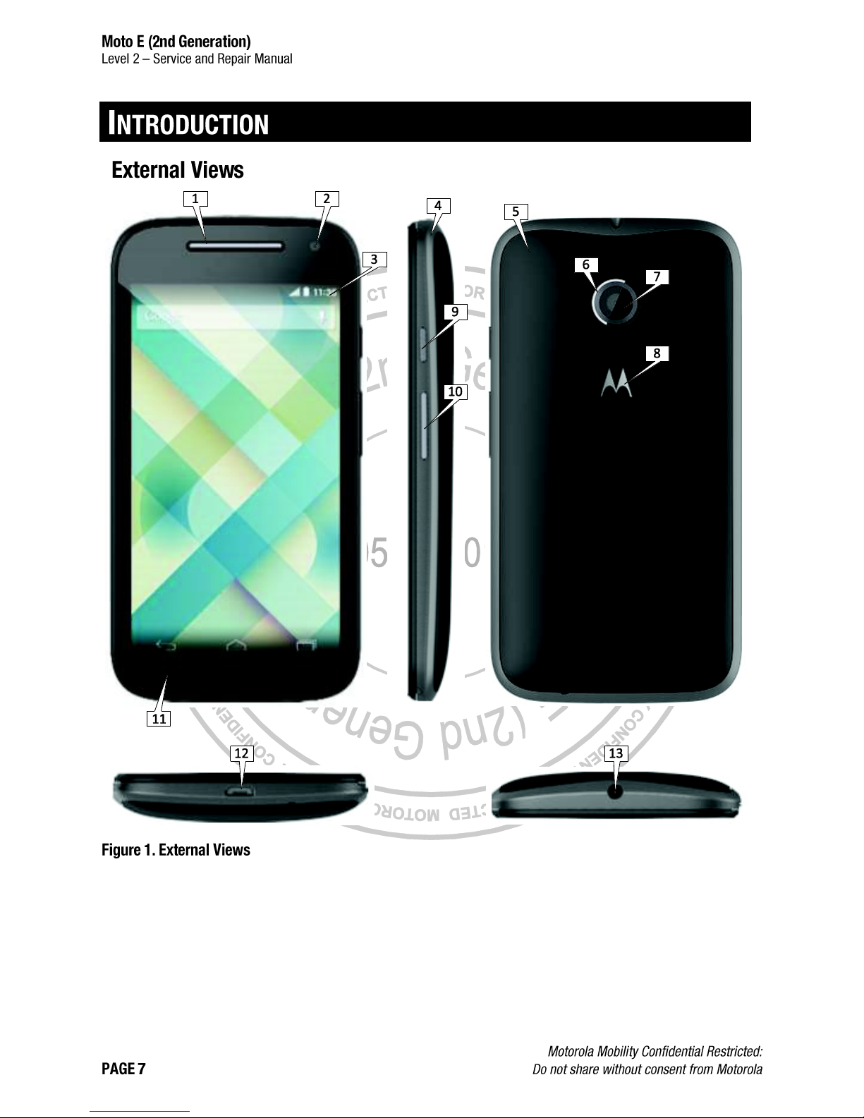
1
Earpiece
2
Front-Facing Imager
3
Main Display
4
Sideband
5
Housing
6
Rear-Facing Imager Deco Ring
7
Rear-Facing Imager
8
Motorola Logo
9
Power Key
10
Volume Key
11
Display Bezel
12
USB Port
13
Headset Jack
Page 9
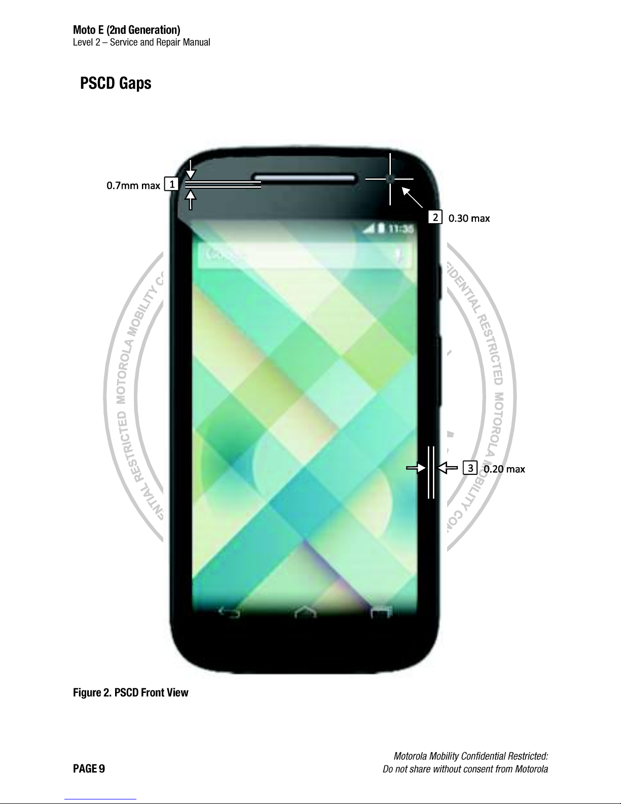
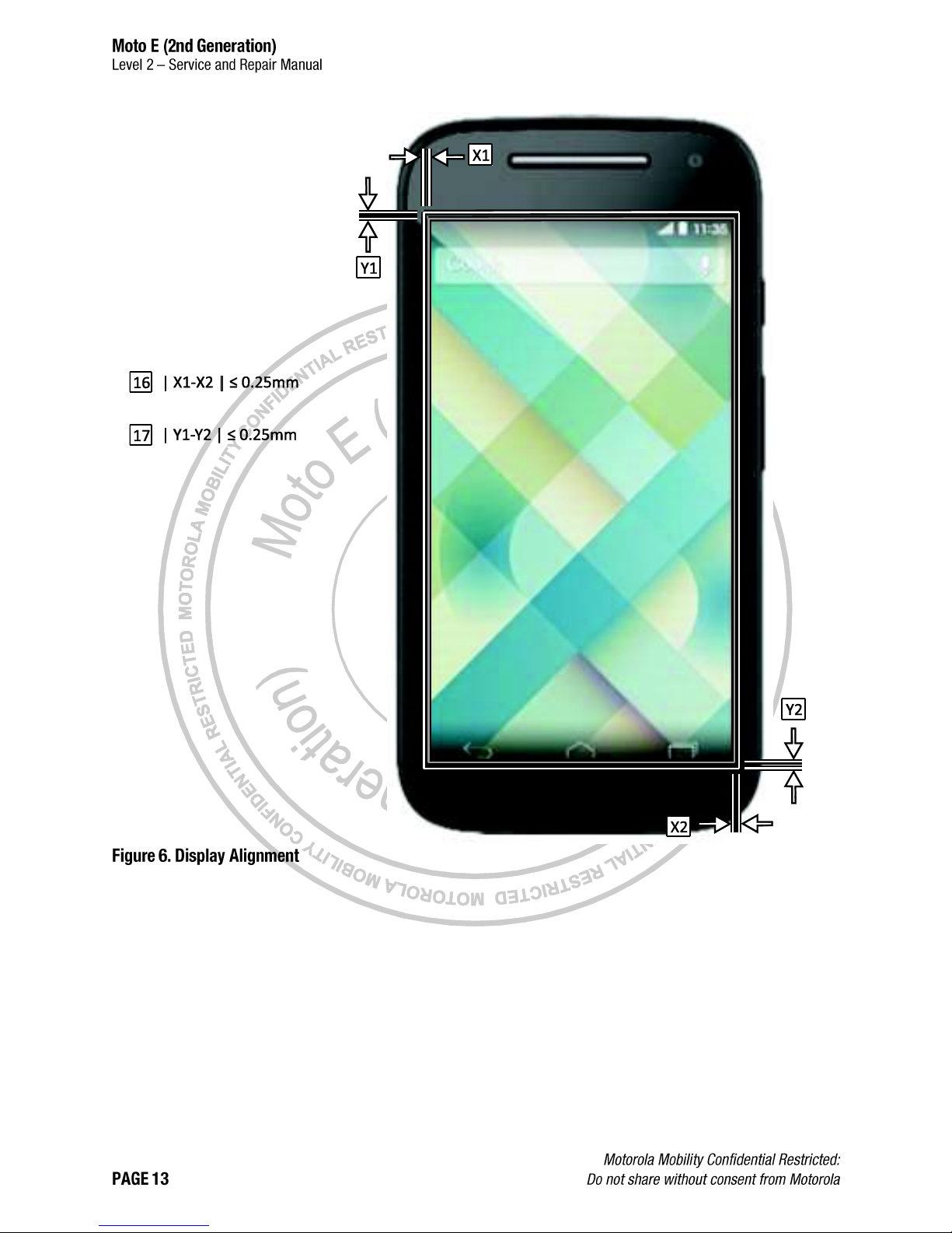
All dimensions are in millimeters (mm). The following gaps are considered maximum allowable without further approval
from a supervisor. Measure gaps at an angle perpendicular to the surface/area being measured. Feeler Gauges must
not be used at an angle as they will give false-positive results.
Page 10
Page 11
Page 12
Page 13
Page 14
1
Earpiece to Main Lens Perimeter
2
Front-Facing Imager to Main Lens Artwork Concentricity
3
Main Lens to Front Housing Perimeter
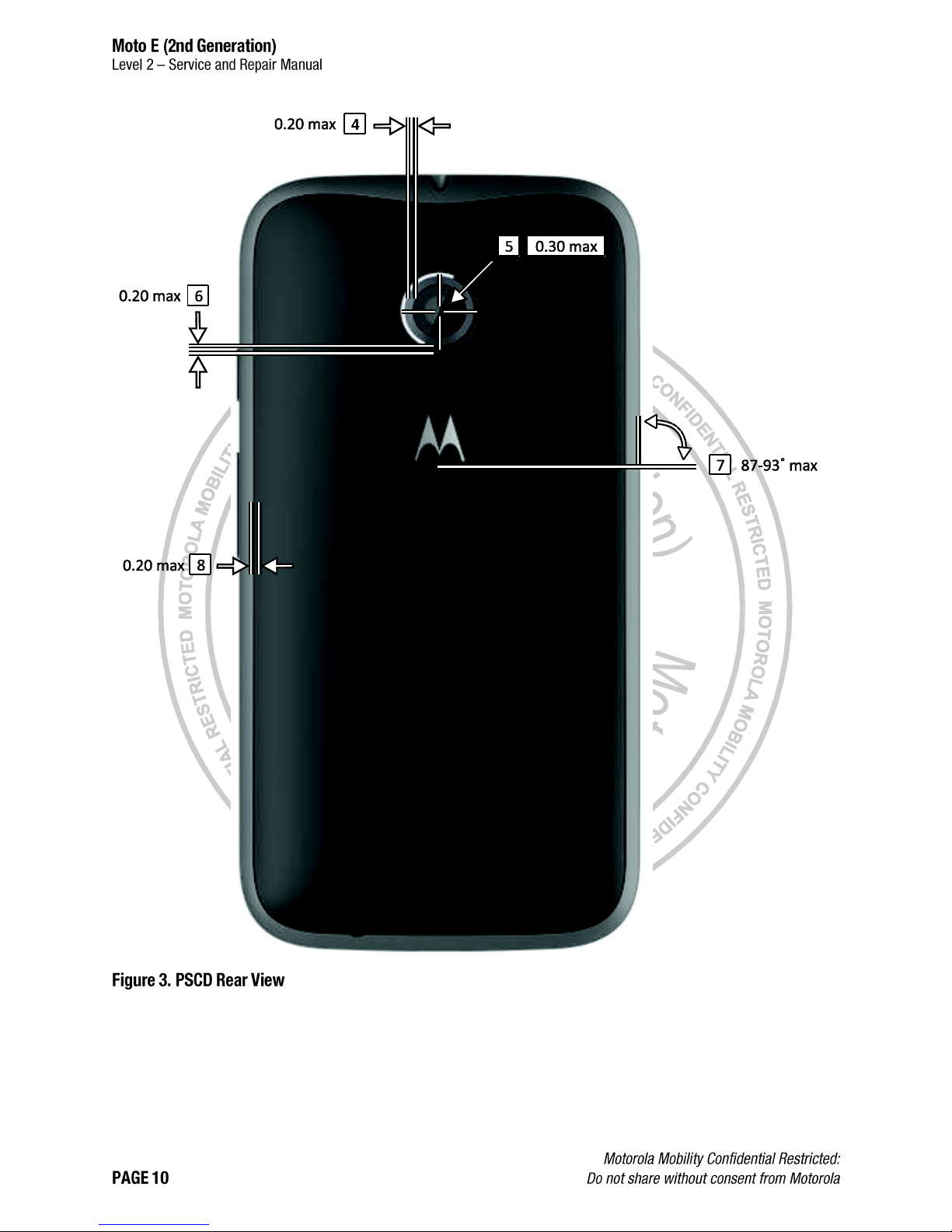
4
Rear-Facing Imager to Deco Ring Perimeter
5
Rear-Facing Imager to Lens Artwork Concentricity
6
Deco Ring to Housing Perimeter
7
Motorola Logo to Housing Side Rotation
8
Housing to Sideband Perimeter
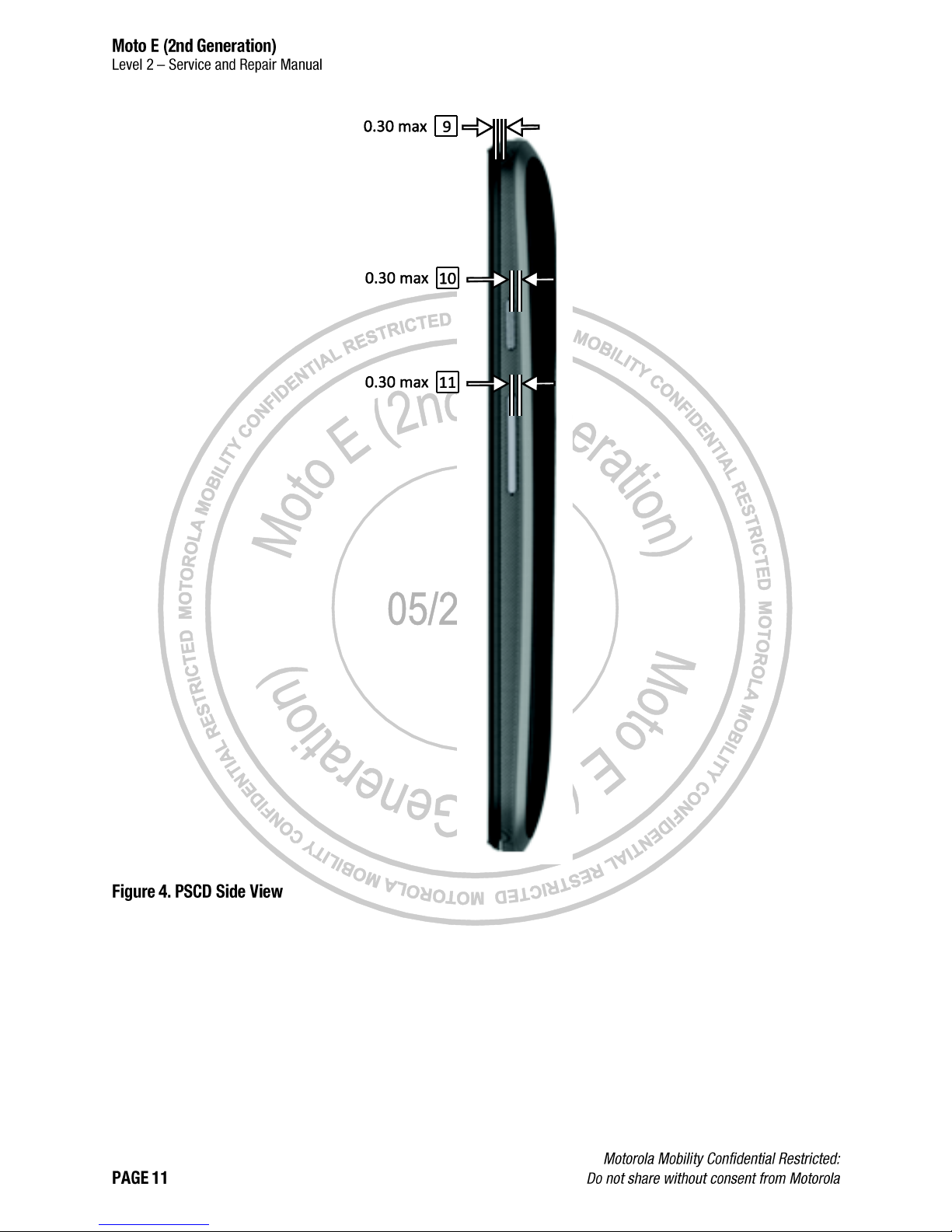
9
Housing to Sideband Perimeter
10
Power Key to Sideband Perimeter
11
Volume Key to Sideband Perimeter
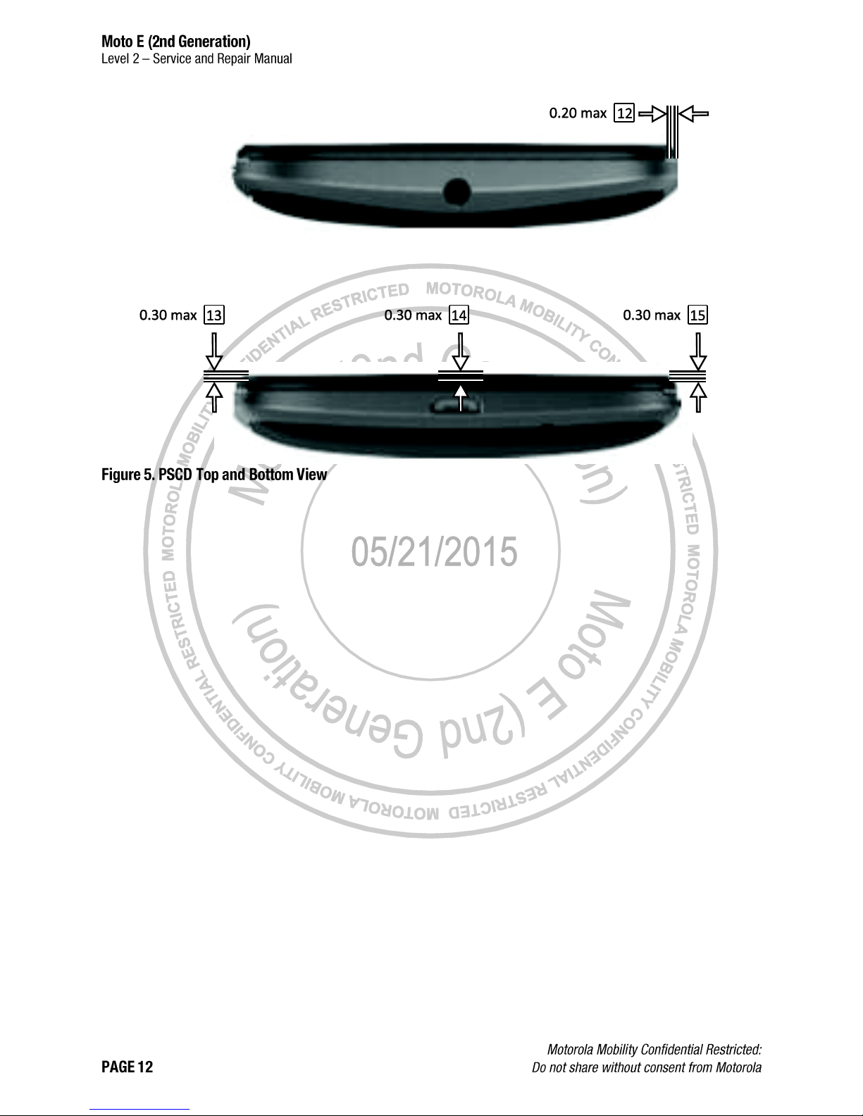
12
Housing to Sideband Step
13
Housing Protrusion over Lens Step (Left)
14
Housing Protrusion over Lens Step (Top and Bottom)
15
Housing Protrusion over Lens Step (Right)
16
Lens Viewing Area Alignment (Horizontal)
17
Lens Viewing Area Alignment (Vertical)
Page 15
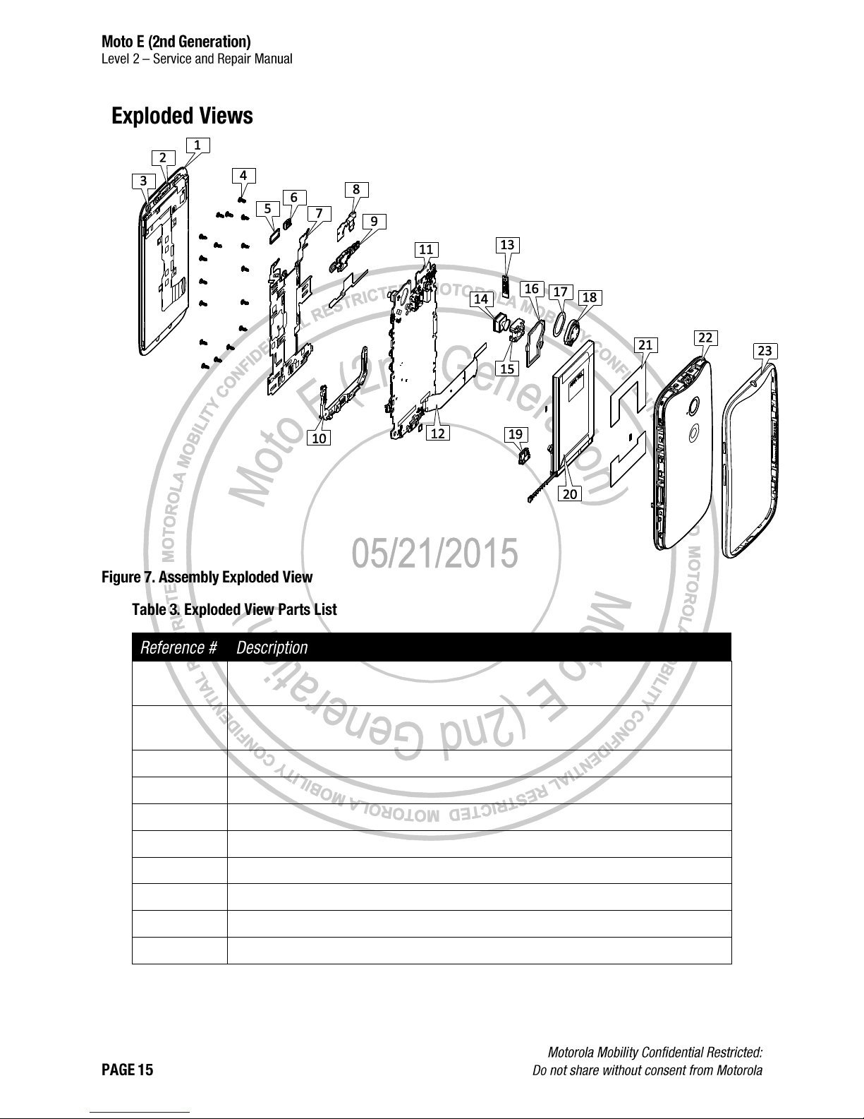
1
ASSEMBLY,DISPLAY,4.5 Inches MDL ASSY,TFT,WITH LENS,INX,PROD,BLACK
ASSY,DISP,4.5 Inches MDL ASSY,TFT,WITH LENS,INX,PROD,WHITE
2
ASSEMBLY,EARPIECE,DECORATIVE
ASSY,EARPC,DECORATIVE,WHITE
3
GSKT,FF IMAGER,STYX
4
SCREW,4.0,UNIWAVE II,DVX
5
GROM,PROX,WITH ADHES
6
TRANSDUCER,SDRP0612HJ05-02-G AAC 6X12X2MM RCVR
7
CHAS,GND PLATE,STYX
8
FLEX,AUDIO
9
HSG,PCB FRAME,TOP,MOLDED,STYX
10
HSG,PCB FRAME,BOTTOM,MOLDED,STYX
Page 16
11
ASSY,PWA,XCVR,STYX 3G,1SIM
ASSY,PWA,XCVR,STYX 3G,AWS
ASSY,PWA,STYX,SPRINT/USC
ASSY,PWA,STYX,EUROPE
ASSY,PWA,STYX,LATAM SS
ASSY,PWA,STYX,NA
ASSY,PWA,STYX,VZW
ASSY,PWA,XCVR,PORT STYX 3G 2SIM
ASSY,PWA,STYX,LATAM DS
ASSY,PWA,STYX,LATAM DS DTV
ASSY,PWA,STYX,EUROPE
ASSY,PWA,XCVR,PORT STYX 3G 2SIM
12
LBL,MEID,STYX
13
CVR,SIM W/ ADHES
CVR,SIM W/ ADHESIVE, WHT
14
IMGR MDL,CMOS,5MP,8.5X8.5X4.55,MIPI,4P,1/5,LAND,2.8V
15
SHLD,TOP CVR CAMR SKT
16
PAD,GSKT LOUD ADHES
17
DIE CUT,ADHES,LOUD
18
TRANSDUCER,OTHR,2V,LOUDSPEAKER, 8OHM, 3.65 X 12 X 17MM, IP67, IN
19
GROM,UUSB,STYX
20
ASSY,BAT,FT40,LI POLYMER,SONY,TYP2390 MAH
21
DIE CUT,ADHES,BATTERY,STYX
22
ASSY,HSG,REAR,STYX,LICORICE
ASSY,HSG,REAR,STYX,WHITE
23
ASSY,HSG,BAND,LICORICE,STYX
ASSY,HSG,BAND,WHITE,STYX
Page 17
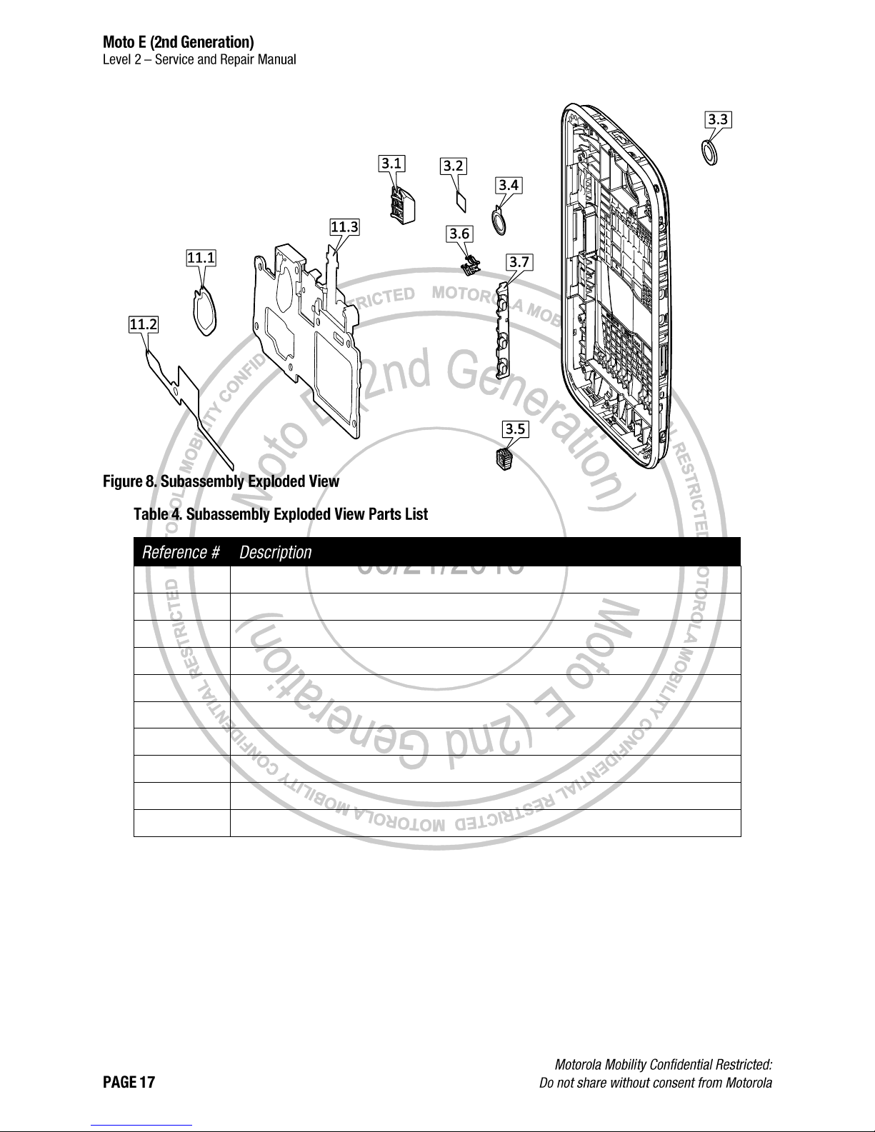
3.1
CONN,JACK, HEADSET, 3.5 MM DIAMETER, 45 DEG SLOPED FRONT, SLVR
3.2
TAPE,ADHES,HEADSETJACK DVX
3.3
LENS,MN CAMR STYX
3.4
GSKT,REAR MN CAMR
3.5
COMP ASSY,GROM PRMRY MIC,STYX
3.6
CONT,SPKR
3.7
BTN,VOL,INNER,MOLDED W/ ADHESIVE,STYX
11.1
DIE CUT,ADHES,SPK PCB FRM
11.2
DIE CUT,ADHES,TOP FRAME,STYX
11.3
ASSEMBLY,FLEX CIRCUIT,HSJ
Page 18
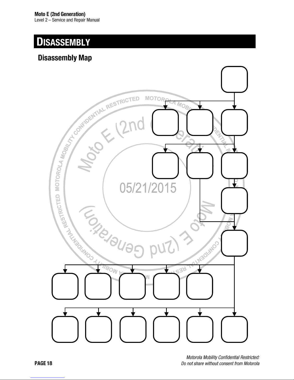
Display
Sideband
Battery
Loudspeaker
Proximity
Grommet
Grounding
Plate
Bottom Spacer
Earpiece
Speaker
Headset Jack
USB Grommet
Rear-Facing
Imager Lens
Top Spacer
PCB
Side Key Pad
Main
Microphone
Grommet
Rear-Facing
Imager
Rear-Facing
Imager Gasket
Front-Facing
Imager Gasket
Earpiece Bezel
Loudspeaker
Gasket
Page 19
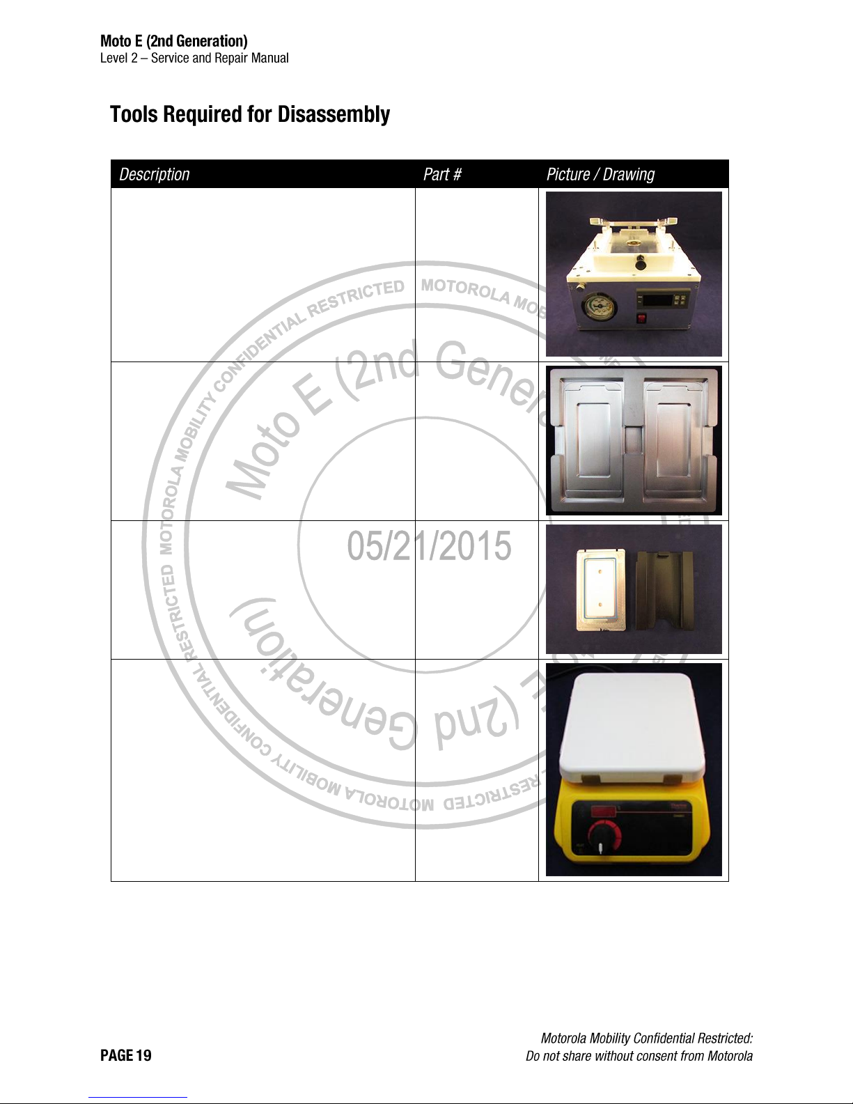
The following tools are required to disassemble the Moto E (2nd Generation) phone.
Generic Lens Removal Fixture*
4-00-X2-10000/
4-00-X7-10000
Lens Heating Nest
(optional – for use with Hot Plate if Oven is not
available)
4-00-X5-10000
Styx Lens Removal Fixture
4-00-X6-10000
“7x”7 Hot Plate
(optional – for reduction of process time if Oven is
not available)**
4-00-Z2-10000
(220V) /
4-00-Z3-10000
(110V)
Page 20
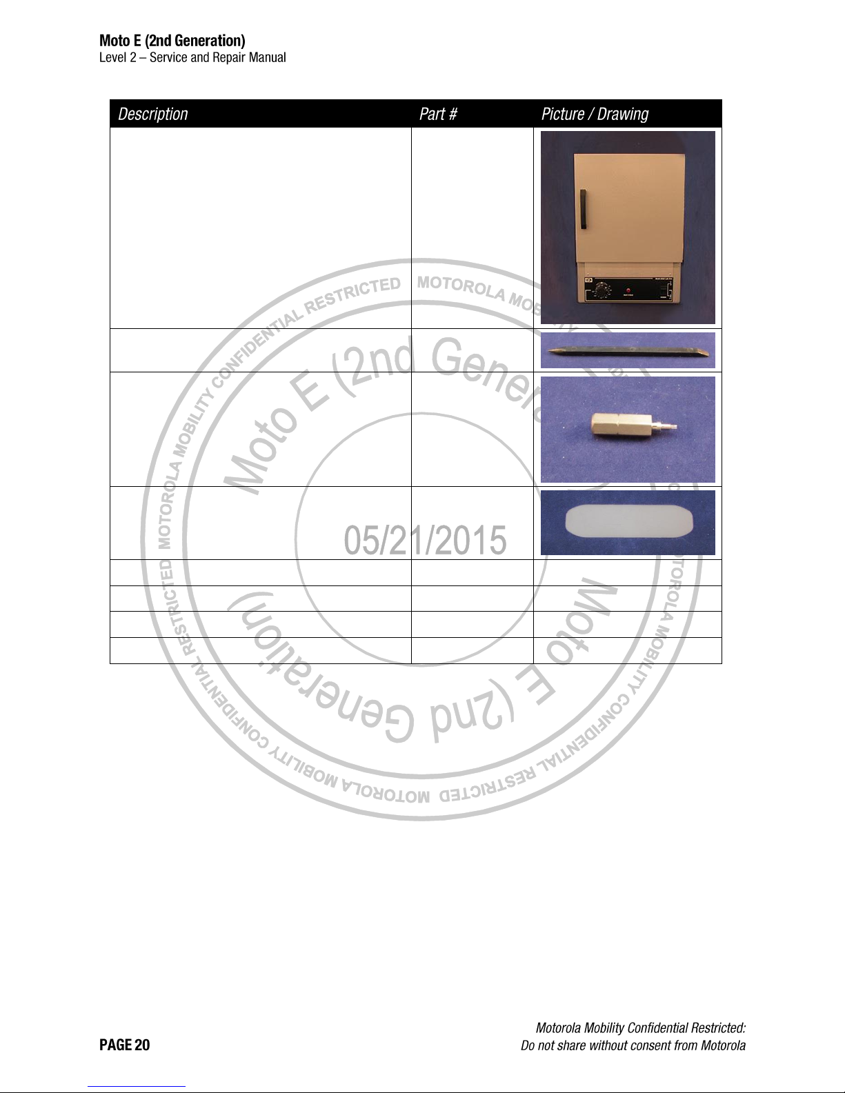
Oven
(optional - for reduction of process time if Hot Plate
and Lens Heating Nest are not available)
--
Blackstick
--
4IP Torx Bit
-Thin Plastic Spudger
0-00-00-40826
Tweezers (Plastic or Plastic-Tipped)
--
--
ESD Mat and Wrist Strap
--
--
Gloves or Finger Collets
--
--
Isopropyl (ISP) Alcohol
--
--
*Generic Lens Removal Fixtures 4-00-X2-10000 and 4-00-X7-10000 are identical tools. The only difference is the
voltage rating. Either the 4-00-X2-10000 or the 4-00-X7-10000 can be used with the Styx Lens Removal Fixture (4-00X6-10000).
**Hot Plates 4-00-Z2-10000 and 4-00-Z3-10000 are identical tools. The only difference is the voltage rating. Either the
220V 4-00-Z2-10000 or the 110V 4-00-Z3-10000 can be used with the Lens Heating Nest (4-00-X5-10000).
Page 21
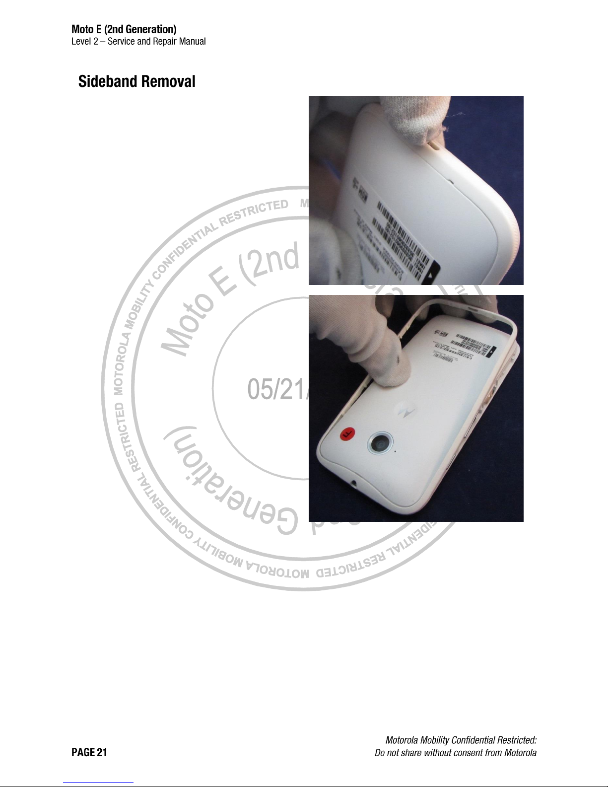
1. Use a fingernail in the USB Port to unsnap the
bottom of the Sideband from the Housing.
2. Peel the Sideband away from the Housing to
disengage the snaps and remove the Sideband.
Page 22
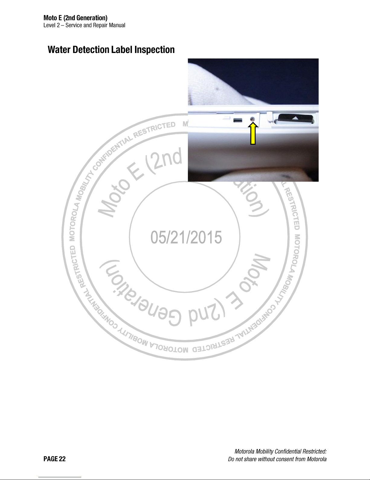
Inspect the Water Detection Label (WDL) visible
through the opening next to the Label Tray, to
verify it is correctly placed and inspect it for signs
of activation.
Page 23
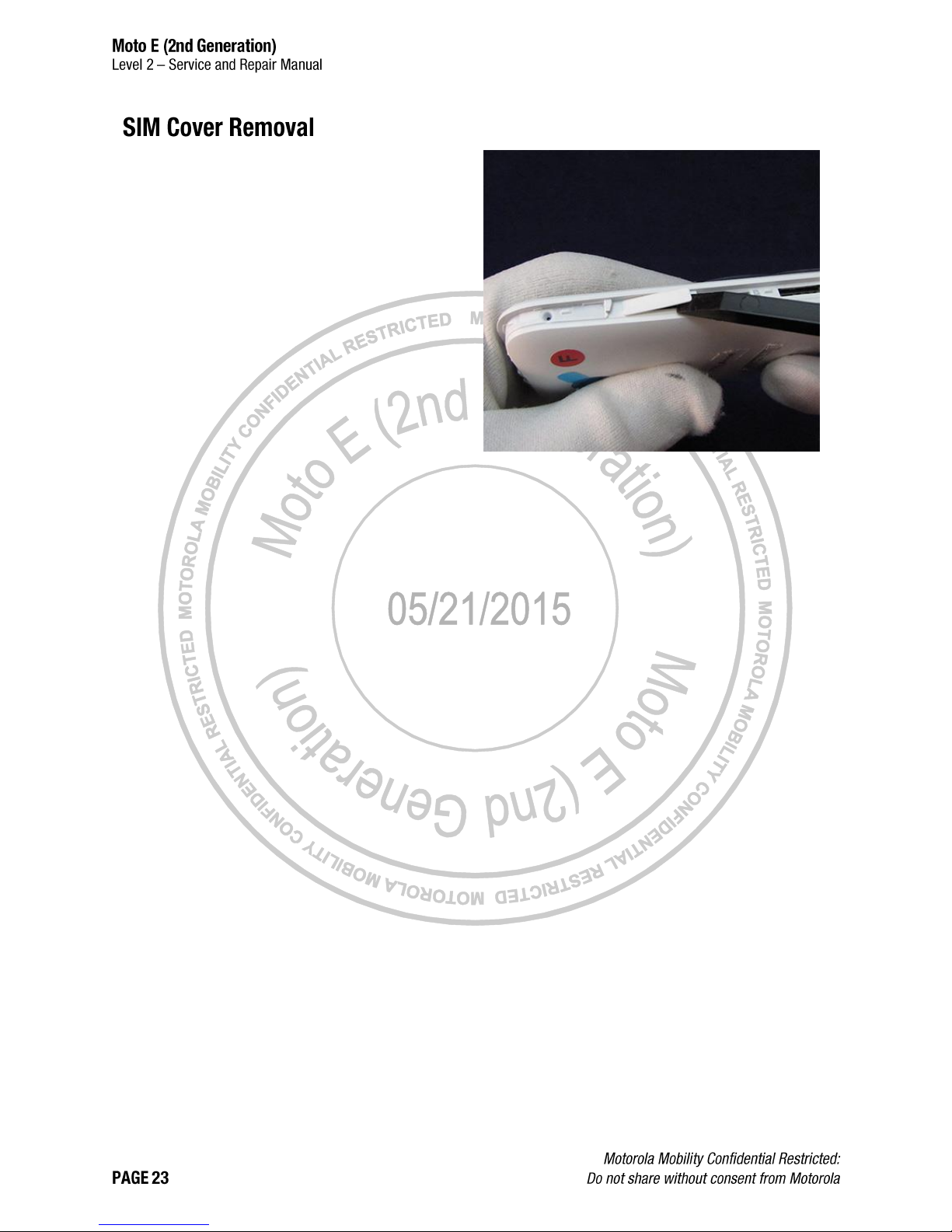
Use the flat end of the Blackstick to unsnap the
SIM Cover from the Housing.
Page 24
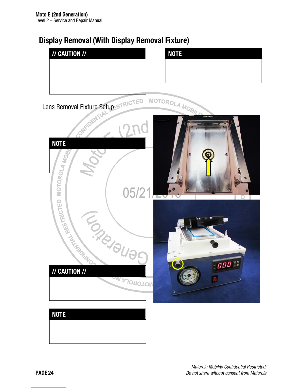
If the controller on the Generic Lens Removal
Fixture must be adjusted, see the user manual on
page 126.
If the Display Lens is damaged, continue to
Display Removal (Damaged Display Lens Only)
on page 30. Do not use the Display Removal
(With Display Removal Fixture) procedure if the
Display Lens is damaged.
Pre-Heat Method A and Pre-Heat Method B are
optional procedures that may be used to reduce
the Display Removal process time.
1. Verify that the Vacuum O-ring is positioned in the
Generic Lens Removal Fixture (4-00-X210000/4-00-X7-10000) as shown.
The Generic Lens Removal Fixture vacuum will
not perform correctly if the Vacuum O-ring is not in
position.
2. Place the Styx Lens Removal Fixture (4-00-X6-
10000) into the Generic Lens Removal Fixture.
3. Press the black power switch (not shown) on the
back of the Generic Lens Removal Fixture to turn
the fixture ON.
4. Turn the vacuum knob (circled) clockwise until it
stops.
5. Wait 5-10 minutes for the Generic Lens Removal
Fixture to warm up to 100 °C (212°F).
Damage to the assembly may occur if the Generic
Lens Removal Fixture is not warmed up to
operating temperature before use.
Page 25
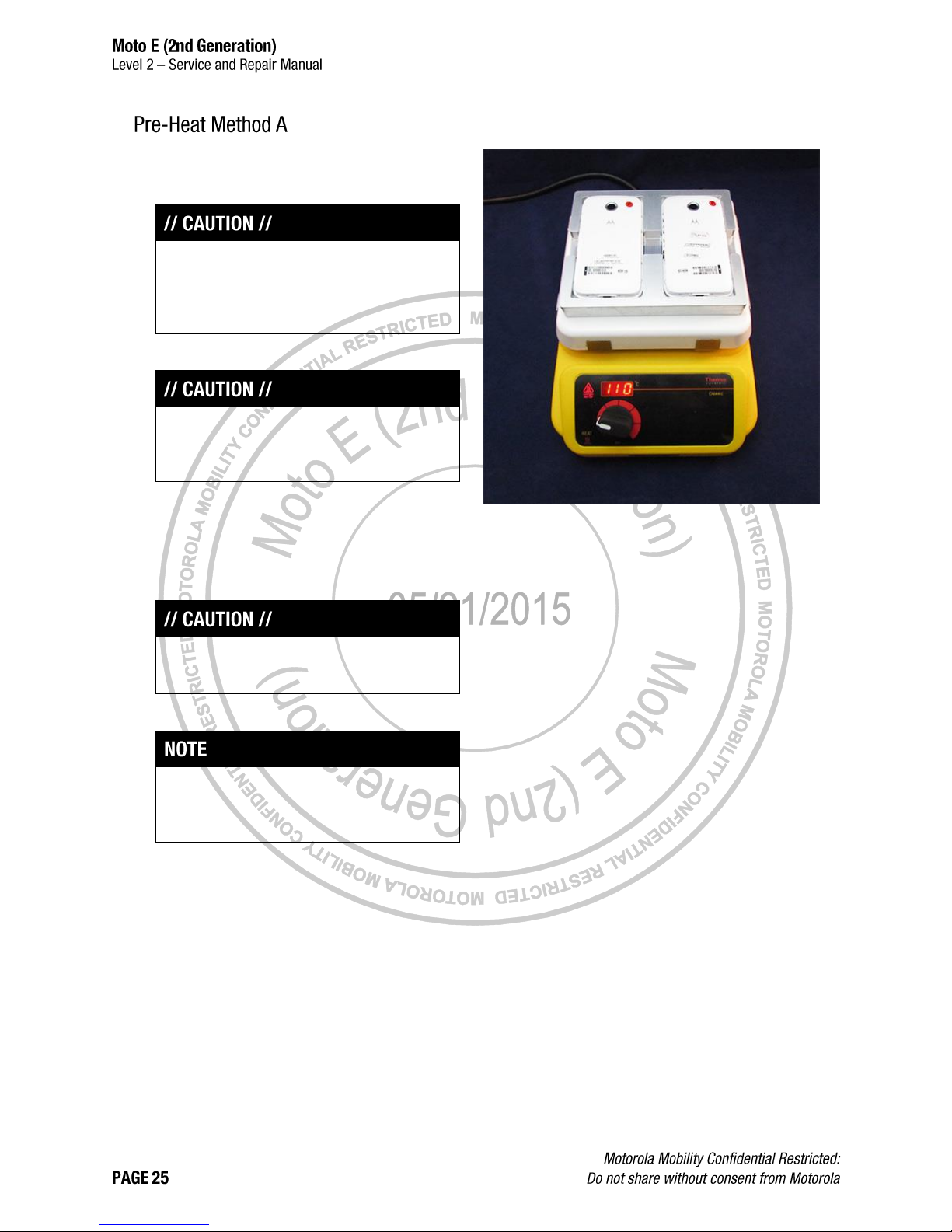
1. Place the Lens Heating Nest (4-00-X5-10000) on
the Hot Plate.
If the Lens Heating Nest and Hot Plate are not
available or not appropriate, use Pre-Heat Method
B on page 26 or skip to Display Removal on page
27.
2. Set the Hot Plate to 110 °C (230 °F).
Do not set the Hot Plate temperature higher than
110 °C (230 °F). Damage to the phone may
occur.
3. Wait 5-10 minutes for the Hot Plate to warm up.
4. Place the phone in the nest.
5. Wait 3 minutes for the Display to warm up.
6. Remove the phone from the nest.
Wear protective gloves when handling heated
phones.
7. Continue to Display Removal on page 27.
For phones with a damaged Display Lens,
continue to Display Removal (Damaged Display
Lens Only) on page 30.
Page 26
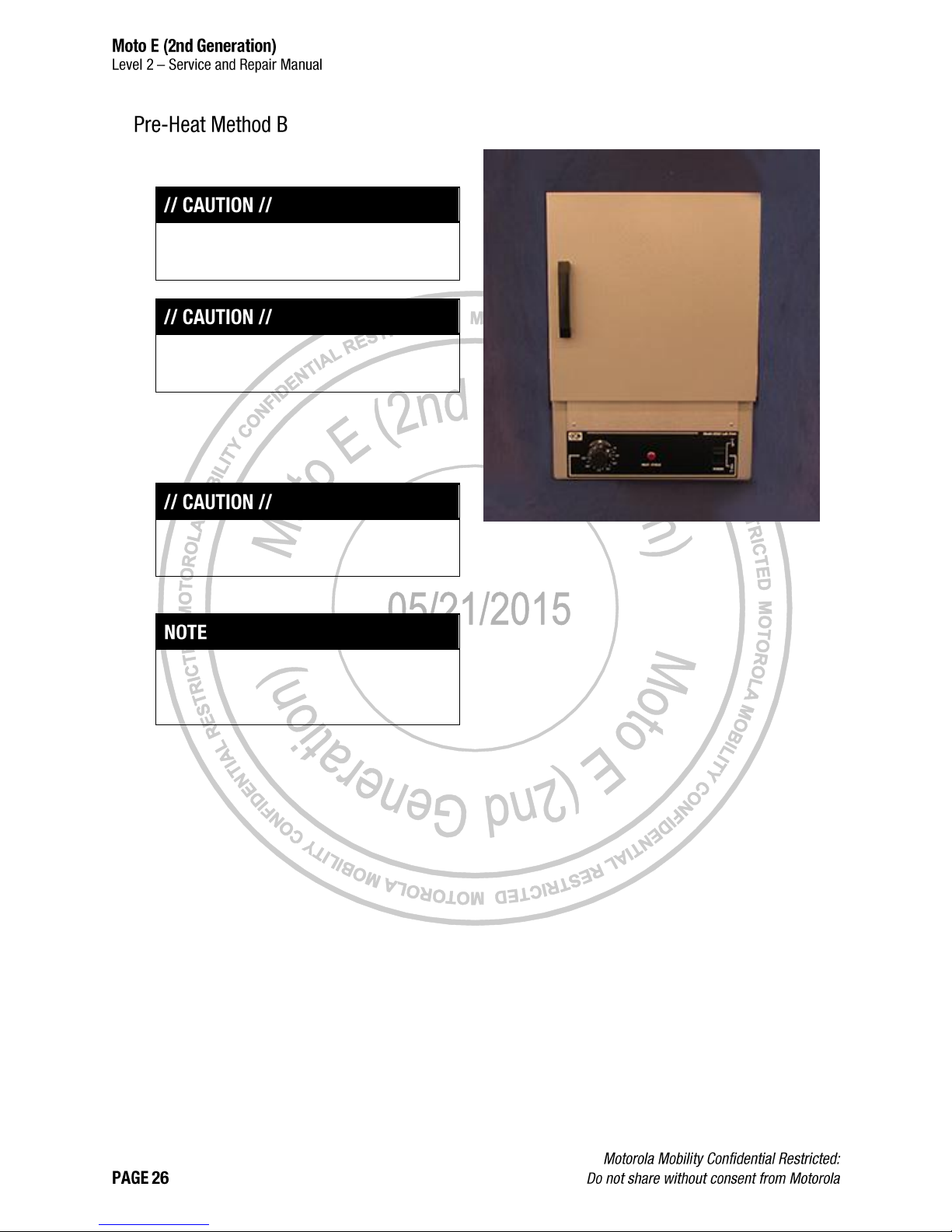
1. Pre-heat the Oven to 70 °C (158 °F).
If the Oven is not available or not appropriate, skip
to Display Removal on page 27.
Do not set the Oven temperature higher than
70 °C (158 °F). Damage to the phone may occur.
2. Place the phone in the Oven.
3. Wait 25 minutes for the Display to warm up.
4. Remove the phone from the Oven.
Wear protective gloves when handling heated
phones.
5. Continue to Display Removal on page 27.
For phones with a damaged Display Lens,
continue to Display Removal (Damaged Display
Lens Only) on page 30.
Page 27
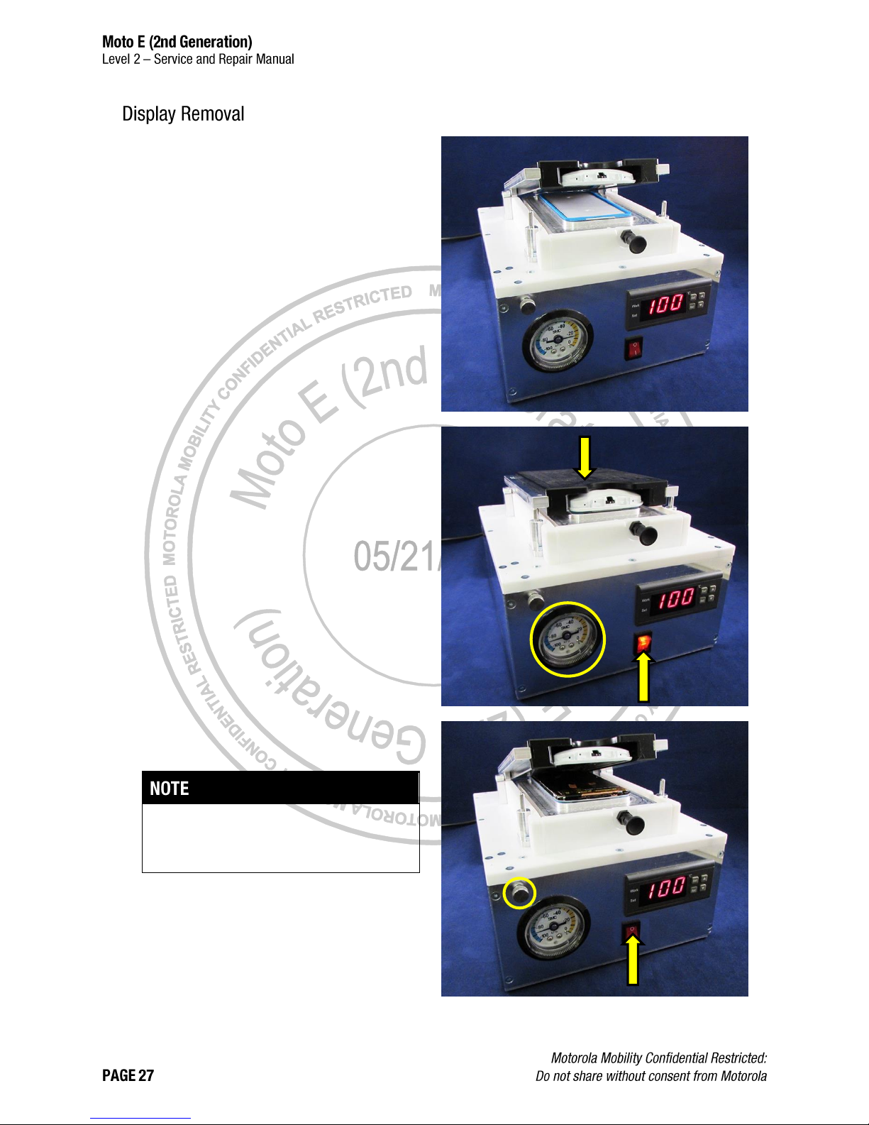
1. Place the phone in the Styx Lens Removal
Fixture with the Display facing down and the
Headset Jack facing the front of the fixture.
2. Press down on the Styx Lens Removal Fixture
and press the red button to turn on the vacuum
pump.
3. Hold the Styx Lens Removal Fixture down until
the gauge (circled) reaches -90 kPa. When the
gauge reaches -90 kPa, remove your hand from
the Styx Lens Removal Fixture.
4. Wait for the Styx Lens Removal Fixture to spring
up.
The lid on the Generic Lens Removal Fixture is
spring loaded, and will automatically open when
the Display is separated from the Housing.
5. Press the red button to turn off the vacuum
pump.
6. Turn the vacuum knob (circled) counter-
clockwise to release the vacuum.
Page 28
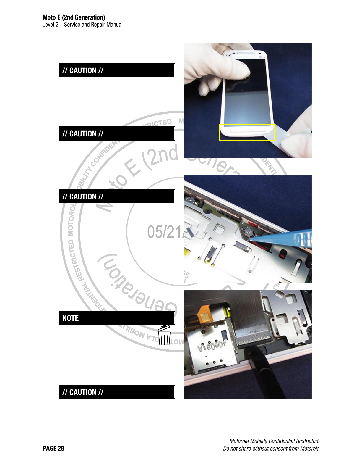
7. Remove the phone from the Styx Lens Removal
Fixture.
Wear protective gloves when handling heated
parts.
8. Use the Thin Plastic Spudger to separate the
remaining adhesive from the USB side of the
phone.
Do not insert the Thin Plastic Spudger farther than
necessary. The Lens may separate from the
Display.
9. Use the Tweezers to disconnect the Battery.
To avoid damage to the Display, the Battery must
be disconnected before disconnecting the Display
Flex.
10. Use the Tweezers to remove the Kapton® Tape
from the Display Flex ZIF Connector Door.
After you remove the Kapton Tape, you
cannot reuse it.
11. Use the Blackstick to open the Display Flex ZIF
Connector Door.
12. Slide the Display Flex free from the ZIF
Connector.
Do not damage the Display Flex.
Page 29
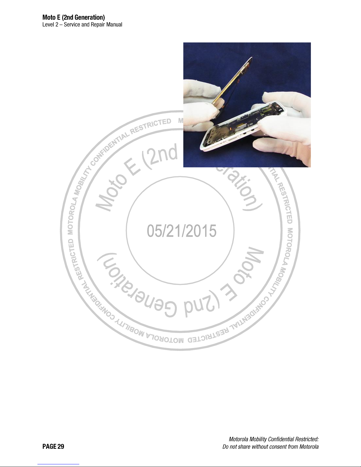
13. Verify that the Display Flex is disconnected and
that no other connection exists between the
Display and the phone assembly.
14. Lift the Display out of the Housing.
Page 30
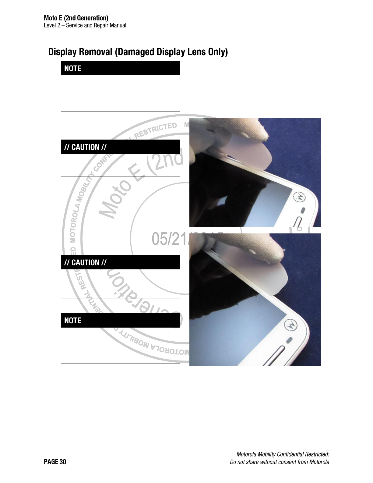
The phone may be pre-heated before Display
removal. See Pre-Heat Method A on page 25 and
Pre-Heat Method B on page 26 for pre-heating
instructions.
1. Slide the Thin Plastic Spudger into the gap
between the Display and the Housing.
This procedure should only be performed if the
Display Lens is damaged.
2. Move the Thin Plastic Spudger around the edge
of the Display to free the adhesive.
Do not insert the Thin Plastic Spudger deeper
than 1 mm. Deeper insertion may separate the
Display and Lens and cause damage.
While moving the Thin Plastic Spudger around the
Display, insert a shim or Thin Plastic Spudger
between the separated edges to prevent the
Display from re-adhering to the Housing.
Page 31

3. When the adhesive has been freed, slightly lift
the Display from the Housing.
To avoid damage to the Display Flex, do not lift
the Display any higher than necessary to
disconnect the Battery and Display Flex.
4. Use the Tweezers to disconnect the Battery.
To avoid damage to the Display, the Battery must
be disconnected before disconnecting the Display
Flex.
5. Use the Tweezers to remove the Kapton Tape
from the Display Flex ZIF Connector Door.
After you remove the Kapton Tape, you
cannot reuse it.
Page 32

6. Use the Blackstick to open the Display Flex ZIF
Connector Door.
7. Slide the Display Flex free from the ZIF
Connector.
Do not damage the Display Flex.
8. Verify that the Display Flex is disconnected and
that no other connection exists between the
Display and the phone assembly.
9. Lift the Display out of the Housing.
Page 33

Use the flat end of the Blackstick to push the Earpiece
Bezel out of the Display.
After you remove the Earpiece Bezel, you
cannot reuse it.
Page 34

Use the Plastic Tweezers to remove the Front-Facing
Imager Gasket from the Display.
After you remove the Front-Facing
Imager Gasket, you cannot reuse it.
Page 35

Use the Tweezers to remove the Proximity Grommet.
After you remove the Proximity Grommet,
you cannot reuse it.
Page 36

10. Use the Blackstick to push the Earpiece Speaker
towards the top edge of the phone. Verify that
the tab on the left side of the Earpiece Speaker
is clear of the retention feature.
11. Use the pointed end of the Blackstick on the
corner of the Earpiece Speaker to pry the
Earpiece Speaker out of the socket.
12. Use the Blackstick and ISP Alcohol to remove
the Earpiece Speaker Adhesive.
Remove the Earpiece Speaker Adhesive only if
the Earpiece Speaker will be reused. If the
Earpiece Speaker will be replaced, skip this step.
Page 37

1. Remove the 4IP Screw from the Grounding
Plate.
After you remove the 4IP Screw, you
cannot reuse it.
2. Slide the Grounding Plate to one side to
disengage one of the snap features, then to the
other side to free the other.
3. Slide the Grounding Plate upwards to disengage
the 2 top snap features.
Page 38

1. Remove the 6 4IP Screws from the Bottom
Spacer.
After you remove the 4IP Screws, you
cannot reuse them.
2. Use the flat end of the Blackstick on the 2
removal features of the Bottom Spacer to
disengage the Housing snaps.
Do not damage the Battery connector or Display
Flex ZIF Connector.
3. Slide the Blackstick under the Bottom Spacer to
remove it from the Housing.
Page 39

If the PCB will be replaced, record the Battery part
number (starts with “SNN”) and reprogram the
Battery part number in the PCB using MotoService
“Battery Link” use case after assembly.
1. Remove the 10 4IP Screws from the PCB.
After you remove the 4IP Screws, you
cannot reuse them.
2. Verify that all 4IP Screws are removed from the
PCB.
3. Use the pointed end of the Blackstick to
disengage the Top Spacer retaining tab.
4. Carefully pull on the right edge of the Housing to
disengage the PCB retaining tab.
Page 40

5. Insert the pointed end of the Blackstick on the
right edge of the PCB, near the Power Key
connector, and slowly pry up to release the PCB.
Verify that the Side Key Pad does not loosen from
the Housing when lifting the PCB.
6. Slide the PCB out of the Housing.
Page 41

1. Remove the Kapton Tape from the Audio ZIF
Connector.
After you remove the Kapton Tape, you
cannot reuse it.
2. Use the Blackstick to open the Audio ZIF
Connector Door.
3. Slide the Audio Flex free from the ZIF Connector.
4. Use the flat end of the Blackstick to disengage
the 2 snap features.
Page 42

5. Use the flat end of the Blackstick to pry the Top
Spacer off the PCB.
The Top Spacer uses a small amount of adhesive
to attach to the PCB. Do not damage the Top
Spacer when removing it from the PCB.
Page 43

1. Use the flat end of the Blackstick on the corners
of the Rear-Facing Imager Shield to raise it.
2. Remove the Rear Facing Imager Shield.
3. Use the pointed end of the Blackstick to free the
Rear-Facing Imager from the socket by pressing
on the retention tabs.
4. Use the Tweezers to remove the Rear-Facing
Imager from the socket.
Page 44

1. Use the flat end of the Blackstick to pry the
Loudspeaker from the PCB at the contact side of
the Loudspeaker.
2. Use the Blackstick and ISP Alcohol to remove
the Loudspeaker Adhesive.
Remove the Loudspeaker Adhesive only if the
Loudspeaker will be reused. If the Loudspeaker
will be replaced, skip this step.
Page 45

Use the flat end of the Blackstick to remove the USB
Grommet from the PCB.
Page 46

Failure to adhere to Safety Critical Note(s) may increase
risk of rupture, burning, or failure to function safely when
used by the customer. Refer to the Battery Safety
Guidelines.
Handle the Battery Pack with care. If dropped to the
floor, it may be internally damaged and must be
scrapped.
Ensure Battery and its insulation are not damaged (e.g.
scratched, dented, punctured) prior to and throughout
assembly.
Prior to assembly, ensure Battery edges and surfaces
are not dented or deformed, and that fixtures and parts
that will contact the Battery are free of foreign material.
Ensure screws and screwdrivers do not contact the
Battery.
1. With 2 hands, carefully twist the Housing
repeatedly to free the Battery Adhesive.
Do not twist the Housing more than necessary.
Only a slight amount of force is required to free
the Battery Adhesive.
If the Battery will be replaced, record the Battery
part number (starts with “SNN”) and reprogram the
Battery part number in the PCB using MotoService
“Battery Link” use case after assembly.
Page 47

1. From the inside of the Housing, pull the Label
Tray out of the Housing.
2. Remove the IMEI Label from the Label Tray.
Page 48

1. Insert the pointed end of the Blackstick into the
Headset Jack.
2. Use the Blackstick to pry the Headset Jack out
of the Housing.
3. Use the Blackstick and ISP Alcohol to remove
the Headset Jack Adhesive.
Remove the Headset Jack Adhesive only if the
Headset Jack will be reused. If the Headset Jack
will be replaced, skip this step.
Page 49

Use the Tweezers to remove the Main Microphone
Grommet from the Housing.
Page 50

Use the Tweezers to remove the Side Key Pad from
the Housing.
Page 51

From the inside of the Housing, use the pointed end
of the Blackstick to push the Rear-Facing Imager
Lens out.
Do not push the Lens free from the outside of the
Housing or remove the Rear-Facing Imager Deco
Ring. The Rear Facing Imager Deco Ring can not
be reassembled at this time.
Page 52

Use the Tweezers to remove the Rear-Facing Imager
Gasket.
Remove the Rear-Facing Imager Gasket only if it
is damaged. If the Rear-Facing Imager Gasket
can be reused, skip this step.
Page 53

The following tools are required for parts refresh of the Moto E (2nd Generation) phone.
PCB Process Fixture
4-00-W6-10000
Lens Assembly Process Fixture
4-00-W9-10000
Blackstick
-Tweezers (Plastic or Plastic-Tipped)
--
--
ESD Mat and Wrist Strap
--
--
Gloves or Finger Collets
--
--
Isopropyl (ISP) Alcohol
--
--
Page 54

1. Use the Blackstick and ISP Alcohol to remove
any remaining adhesive in the Battery pocket.
2. Use the Blackstick and ISP Alcohol to clean any
remaining adhesive from the Display ledge.
Page 55

1. Use the Blackstick and ISP Alcohol to remove
any remaining adhesive from where the Top
Carrier attaches to the PCB.
2. Use the Blackstick and ISP Alcohol to remove
any remaining adhesive from where the
Loudspeaker and Loudspeaker Gasket attaches
to the PCB.
3. Use the Tweezers to remove the PCB Kapton
Tape from the PCB Shields.
Page 56

4. Use the Tweezers to remove the Display ZIF
Connector pad.
Remove the Display ZIF Connector
pad only if it is damaged or if thermal
work will be performed on the PCB.
After you remove it, you cannot reuse
it.
5. Verify that the Display ZIF Connector Door is
open.
6. Use the Tweezers to remove the Audio ZIF
Connector pad.
Remove the Audio ZIF Connector
pad only if it is damaged or if thermal
work will be performed on the PCB.
After you remove it, you cannot reuse
it.
7. Verify that the Audio ZIF Connector Door is
open.
Page 57

Failure to adhere to Safety Critical Note(s) may increase
risk of rupture, burning, or failure to function safely when
used by the customer. Refer to the Battery Safety
Guidelines.
Handle the Battery Pack with care. If dropped to the
floor, it may be internally damaged and must be
scrapped.
Ensure Battery and its insulation are not damaged (e.g.
scratched, dented, punctured) prior to and throughout
assembly.
Prior to assembly, ensure Battery edges and surfaces
are not dented or deformed, and that fixtures and parts
that will contact the Battery are free of foreign material.
Ensure screws and screwdrivers do not contact the
Battery.
1. Use the Blackstick and ISP Alcohol to remove
any adhesive residue from the Battery.
To prevent damage, do not allow sharp tools or
screws to come in contact with the Battery.
2. Inspect the Battery to verify it is not creased,
crushed, or punctured.
3. If the Battery foil pack is wrinkled, slide the flat
edge of the Blackstick against the foil pack to
smooth out all wrinkles.
Page 58

1. Use the Blackstick and ISP Alcohol to remove
any remaining IMEI Label adhesive from the
Label Tray.
2. Inspect the Label Tray to verify it is not cracked,
creased, or otherwise damaged.
Page 59

1. Use the Blackstick and ISP Alcohol to remove
any remaining adhesive from the edge of the
Display.
Use care when cleaning the Display. Do not
separate the Display from the Lens or damage the
Display Flex.
2. Inspect the Display Flex to verify it is not torn,
creased, or otherwise damaged.
Page 60

ASSEMBLY,EARPIECE,DECORATIVE
ASSY,EARPC,DECORATIVE,WHITE
1
GSKT,FF IMAGER,STYX
2
ASSEMBLY,DISPLAY,4.5 Inches MDL ASSY,TFT,WITH LENS,INX,PROD,BLACK"
ASSY,DISP,4.5 Inches MDL ASSY,TFT,WITH LENS,INX,PROD,WHITE
3
Page 61

1. Place the Inlay in the Lens Assembly Process
Fixture (4-00-W9-10000) as shown.
2. Place the Display in the Lens Assembly Process
Fixture (4-00-W9-10000).
Page 62

3. Remove the Front-Facing Imager Gasket from
the carrier.
4. Place the Front-Facing Imager Gasket into the
fixture using the pins to align it.
5. Press down on the Front-Facing Imager Gasket
for 5 seconds to secure it to the Display.
6. Remove the adhesive liner from the Earpiece
Bezel.
7. Place the Earpiece Bezel into the fixture. The
bezel will align to the cutout in the fixture Inlay.
8. Press down on the Earpiece Bezel for 5 seconds
to secure it to the Display.
9. Remove the Display from the fixture.
10. Remove the liners from the Front-Facing Imager
Gasket and Earpiece Bezel.
Page 63

DIE CUT,ADHES,SPK PCB FRM
1
DIE CUT,ADHES,TOP FRAME,STYX
2
COMP ASSY,FRM FLX TOP,STYX
3
1. Use the Blackstick and ISP Alcohol to remove
the Top Spacer Adhesive and Loudspeaker-Side
Adhesive from the Top Spacer.
2. Place the Top Spacer in the PCB Process
Fixture (4-00-W6-10000).
Page 64

3. Remove the Loudspeaker-Side Adhesive from
the carrier.
4. Place the Loudspeaker-Side Adhesive in the
fixture over the Top Spacer. Align the adhesive
using the cutout in the fixture and the tab on the
adhesive liner.
5. Press down on the Loudspeaker-Side Adhesive
to secure it to the Top Spacer.
6. Remove the Top Spacer Adhesive from the
carrier.
7. Place the Top Spacer Adhesive in the fixture
over the Top Spacer. Align the adhesive using
the pin in the fixture and the rectangular cutout in
the Top Spacer.
8. Press down on the Top Spacer Adhesive to
secure it to the Top Spacer.
Page 65

Display
Labels
Loudspeaker
Gasket
Proximity
Grommet
Grounding
Plate
Bottom Spacer
Earpiece
Speaker
Headset Jack
USB Grommet
Rear-Facing
Imager Lens
Top Spacer
PCB
Side Key Pad
Main
Microphone
Grommet
Rear-Facing
Imager
Loudspeaker
Label Tray
Battery
Adhesive
Battery
ZIF Connector
Pads
Screws
Sideband
Housing
Rear-Facing
Imager Gasket
Display
Adhesive
Housing Prep
Page 66

The following tools are required to assemble the Moto E (2nd Generation) phone.
Loudspeaker Adhesive Alignment Fixture
4-00-W5-10000
PCB Process Fixture
4-00-W6-10000
Front Side Process Fixture
4-00-W8-10000
Lens Assembly Process Fixture
4-00-W9-10000
Cleaning Cover
--
Page 67

Press
19501980
Blackstick
--
3IP Torx Bit
--
Torque Driver (Adjustable)
-Tweezers (Plastic or Plastic-Tipped)
--
--
ESD Mat and Wrist Strap
--
--
Gloves or Finger Collets
--
--
Isopropyl (ISP) Alcohol
--
--
Cotton Swabs
--
--
3M AP-111 Adhesion Promoter
--
Page 68

ASSY,HSG,REAR,STYX,LICORICE
ASSY,HSG,REAR,STYX,WHITE
1
LENS,REAR
2
1. Remove the Rear-Facing Imager Lens from the
carrier.
2. Use the Tweezers to place the Rear-Facing
Imager Lens into the pocket of the Rear-Facing
Imager Deco Ring.
3. Press down on the Rear-Facing Imager Lens for
5 seconds to secure it to the Rear-Facing Imager
Deco Ring.
When securing the Rear-Facing Imager Lens, do
not push the Rear-Facing Imager Deco Ring free
of the Housing.
4. Verify the Rear-Facing Imager outer liner is in
position.
Page 69

ASSY,HSG,REAR,STYX,LICORICE
ASSY,HSG,REAR,STYX,WHITE
1
GSKT,REAR MN CAMR
2
1. Remove the Rear-Facing Imager Gasket from
the carrier.
2. Place the Rear-Facing Imager Gasket in the
Rear-Facing Imager Lens pocket.
3. Press down on the Rear-Facing Image Gasket to
secure it to the Lens pocket in the Housing.
4. Remove the liner from the Rear-Facing Imager
Gasket.
Page 70

ASSY,HSG,REAR,STYX,LICORICE
ASSY,HSG,REAR,STYX,WHITE
1
SIDE KEY CONNECTOR
2
1. Place the Side Key Pad into the pocket of the
Housing.
Page 71

2. Verify 3 points for correct alignment:
The Side Key Pad should fit around the 3
Housing posts.
The Side Key Pad should be even with or
below the inner ledge of the Housing.
The Side Key Pad should protrude slightly
from each of the 3 holes on the side of the
Housing.
Page 72

3. Test the Side Key Pad. Pressing the buttons on
the side of the Housing should cause the buttons
to flex inward. The buttons should spring back
immediately upon release.
Page 73

ASSY,HSG,REAR,STYX,LICORICE
ASSY,HSG,REAR,STYX,WHITE
1
GROM,MIC
2
1. Place the Main Microphone Grommet into the
pocket of the Housing. The orientation feature
points away from the Housing edge.
2. Press down on the Main Microphone Grommet
for 3 seconds to secure it in the Housing.
Page 74

ASSY,HSG,REAR,STYX,LICORICE
ASSY,HSG,REAR,STYX,WHITE
1
HSJ, STYX
2
1. Remove the Headset Jack Adhesive from the
carrier.
2. Apply the Headset Jack Adhesive to the Headset
Jack. The adhesive should not overhang the
lower edge of the Headset Jack.
3. Press down on the Headset Jack Adhesive to
secure it to the Headset Jack.
Page 75

4. Remove the Headset Jack Gasket from the
carrier.
5. Apply the Headset Jack Gasket to the Headset
Jack. The gasket should not overhang the edges
of the Headset Jack.
6. Remove the liner from the Headset Jack Gasket.
7. Remove the liner from the Headset Jack
Adhesive.
8. Place the Headset Jack into the pocket of the
Housing, angling the top of the jack into the
pocket first.
9. Press down on the Headset Jack to secure it in
the Housing.
Do not damage the Headset Jack contacts.
Page 76

ASSY,HSG,REAR,STYX,LICORICE
ASSY,HSG,REAR,STYX,WHITE
1
LBL,MEID,STYX
2
1. Route the Label Tray through the slots in the
Housing. The Label Tray fits under the bar inside
the Housing and out the slot on the side of the
Housing.
Page 77

2. Pull the Label Tray through the slot on the side of
the Housing until it stops.
Page 78

ASSY,BAT,FT40,LI POLYMER,SONY,TYP2390 MAH
ALTER SNN5955A for LG
1
DIE CUT,ADHES,BATTERY,STYX
2
Failure to adhere to Safety Critical Note(s) may increase
risk of rupture, burning, or failure to function safely when
used by the customer. Refer to the Battery Safety
Guidelines.
Handle the Battery Pack with care. If dropped to the
floor, it may be internally damaged and must be
scrapped.
Ensure Battery and its insulation are not damaged (e.g.
scratched, dented, punctured) prior to and throughout
assembly.
Prior to assembly, ensure Battery edges and surfaces
are not dented or deformed, and that fixtures and parts
that will contact the Battery are free of foreign material.
Ensure screws and screwdrivers do not contact the
Battery.
Page 79

1. Remove the Battery Adhesive from the carrier.
2. Place the Battery Adhesive in the PCB Process
Fixture (4-00-W6-10000) using the pins to align
it.
3. Place the alignment lid on the fixture.
Page 80

4. Place the Battery in the pocket. The Battery
Connector aligns to the cutout in the alignment
lid.
5. Press down on the Battery to secure the
adhesive.
Page 81

ASSY,HSG,REAR,STYX,LICORICE
ASSY,HSG,REAR,STYX,WHITE
1
ASSY,BAT,FT40,LI POLYMER,SONY,TYP2390 MAH
ALTER SNN5955A for LG
2
Failure to adhere to Safety Critical Note(s) may increase
risk of rupture, burning, or failure to function safely when
used by the customer. Refer to the Battery Safety
Guidelines.
Handle the Battery Pack with care. If dropped to the
floor, it may be internally damaged and must be
scrapped.
Ensure Battery and its insulation are not damaged (e.g.
scratched, dented, punctured) prior to and throughout
assembly.
Prior to assembly, ensure Battery edges and surfaces
are not dented or deformed, and that fixtures and parts
that will contact the Battery are free of foreign material.
Ensure screws and screwdrivers do not contact the
Battery.
Page 82

If a new Battery or PCB is used, record the Battery
part number (starts with “SNN”) and reprogram the
Battery part number in the PCB using MotoService
“Battery Link” use case after assembly.
1. Slide the Label Tray into the Housing,
underneath the Battery. Only a small portion of
the Label Tray remains visible.
2. Place the Housing in the Front Side Process
Fixture (4-00-W8-10000).
Page 83

3. Verify that the Label Tray is positioned in the
recess in the Housing.
4. Place the Battery in the Housing pocket. The
Battery Connector aligns to the cutout feature in
the pocket corner.
Page 84

5. Press down on the Battery to secure it in the
Housing.
6. Place the Front Side Process Fixture (4-00-W8-
10000) in the Press (19501980).
Page 85

7. Hold the Battery Connector out of the Housing
pocket.
Do not damage the Battery Connector.
Keep hands away form the press head during
operation. Injury and/or damage to equipment may
occur.
8. Press the Battery for 10 seconds to secure it to
the Housing.
Page 86

ASSY,PWA,XCVR,STYX 3G,1SIM
ASSY,PWA,XCVR,STYX 3G,AWS
ASSY,PWA,STYX,SPRINT/USC
ASSY,PWA,STYX,EUROPE
ASSY,PWA,STYX,LATAM SS
ASSY,PWA,STYX,NA
ASSY,PWA,STYX,VZW
1
IMGR MDL,CMOS,5MP,8.5X8.5X4.55,MIPI,4P,1/5,LAND,2.8V
2
SHLD,TOP CVR CAMR SKT
3
1. Place the Rear-Facing Imager into the PCB
socket. The dot on the Rear-Facing Imager
aligns with the hole in the socket.
2. Press the Rear-Facing Imager to secure it in the
socket.
Page 87

3. Remove the Rear-Facing Imager protective liner.
Do not discard the protective liner.
4. Place the Rear-Facing Imager Shield over the
Rear-Facing Imager. The slots on the sides of
the Shield align with the spring features on the
sides of the Imager socket.
5. Press the Rear-Facing Imager Shield to secure it
over the socket.
6. Apply the Rear-Facing Imager protective liner to
the Rear-Facing Imager.
Page 88

ASSY,PWA,XCVR,STYX 3G,1SIM
ASSY,PWA,XCVR,STYX 3G,AWS
ASSY,PWA,STYX,SPRINT/USC
ASSY,PWA,STYX,EUROPE
ASSY,PWA,STYX,LATAM SS
ASSY,PWA,STYX,NA
ASSY,PWA,STYX,VZW
1
PAD,GSKT LOUD ADHES
2
Page 89

1. Place the PCB in the PCB Process Fixture (4-00-
W6-10000).
2. Place the alignment tab in the fixture.
Page 90

3. Remove the Loudspeaker Gasket from the
carrier.
4. Place the Loudspeaker Gasket into the fixture
using the pins in the fixture and alignment tab to
align it.
5. Press down on the Loudspeaker Gasket to
secure it to the PCB.
Page 91

ASSY,PWA,XCVR,STYX 3G,1SIM
ASSY,PWA,XCVR,STYX 3G,AWS
ASSY,PWA,STYX,SPRINT/USC
ASSY,PWA,STYX,EUROPE
ASSY,PWA,STYX,LATAM SS
ASSY,PWA,STYX,NA
ASSY,PWA,STYX,VZW
1
DIE CUT,ADHES,LOUD
2
TRANSDUCER,OTHR,2V,LOUDSPEAKER, 8OHM, 3.65 X 12 X 17MM, IP67, IN"
3
Page 92

1. Remove the Loudspeaker Adhesive liner from
the Loudspeaker Adhesive carrier.
2. Place the Loudspeaker Adhesive carrier on the
Loudspeaker Adhesive Assembly Alignment
Fixture (4-00-W5-10000).
3. Place the alignment lid on the fixture.
Page 93

4. Place the Loudspeaker on the adhesive, aligning
the copper contacts to the cutout in the
alignment lid.
5. Press down on the Loudspeaker to secure the
adhesive.
6. Place the PCB into the PCB Processes Fixture
(4-00-W6-10000).
Page 94

7. Place the alignment lid on the fixture.
8. Place the Loudspeaker into the pocket of the
alignment lid.
9. Place the press tool over the pins in the
alignment lid.
10. Press the Loudspeaker for 5 seconds to secure it
to the PCB.
Page 95

ASSY,PWA,XCVR,STYX 3G,1SIM
ASSY,PWA,XCVR,STYX 3G,AWS
ASSY,PWA,STYX,SPRINT/USC
ASSY,PWA,STYX,EUROPE
ASSY,PWA,STYX,LATAM SS
ASSY,PWA,STYX,NA
ASSY,PWA,STYX,VZW
1
PAD,PROX HSJ FLX ZIF SPRT
2
PAD,MN DISP FLX ZIF SPRT
3
DIE CUT,LDL
N/A
1. Remove the Display ZIF Connector pad from the
carrier.
2. Place the Display ZIF Connector pad, aligning it
to the etched markings on the PCB.
Page 96

3. Remove the Audio ZIF Connector pad from the
carrier.
4. Place the Audio ZIF Connector pad, aligning it to
the etched markings on the PCB.
5. Remove the WDL from the carrier.
6. Place the WDL on the PCB as shown, aligning it
to the etched markings on the PCB.
Page 97

ASSY,PWA,XCVR,STYX 3G,1SIM
ASSY,PWA,XCVR,STYX 3G,AWS
ASSY,PWA,STYX,SPRINT/USC
ASSY,PWA,STYX,EUROPE
ASSY,PWA,STYX,LATAM SS
ASSY,PWA,STYX,NA
ASSY,PWA,STYX,VZW
1
GROM,UUSB,STYX
2
1. Remove the USB Grommet from the carrier.
2. Place the side of the USB Grommet without
adhesive over the shield side of the USB
Connector.
Page 98

3. Wrap the USB Grommet around the USB
Connector.
4. Press the USB Grommet to secure it to the USB
Connector.
5. Verify the USB Grommet is fully seated and does
not overlap the USB port.
Page 99

ASSY,PWA,XCVR,STYX 3G,1SIM
ASSY,PWA,XCVR,STYX 3G,AWS
ASSY,PWA,STYX,SPRINT/USC
ASSY,PWA,STYX,EUROPE
ASSY,PWA,STYX,LATAM SS
ASSY,PWA,STYX,NA
ASSY,PWA,STYX,VZW
1
COMP ASSY,FRM FLX TOP,STYX
2
1. Remove all protective and adhesive liners from
the Top Spacer.
2. Verify that the Audio Flex is extended from Top
Spacer.
3. Place the Top Spacer on the PCB, aligning it to
the pins and PCB features.
Page 100

4. Wrap the Audio Flex around top of PCB and
insert it into the Audio Flex ZIF Connector. Use
the white line as a guide for insertion depth.
5. Slide a fingertip across the Audio Flex ZIF
Connector Door to close it.
6. Apply Kapton Tape to the Audio Flex ZIF
Connector Door.
 Loading...