

Motorola MC1378FN, MC1378P Datasheet
Order this document by MC1378/D
The MC1378 is a bipolar composite video overlay encoder and
microcomputer synchronizer. The MC1378 contains the complete encoder
function of the MC1377, i.e., quadrature color modulators, RGB matrix, and
blanking level clamps, plus a complete complement of synchronizers to lock
a microcomputer–based video source to any remote video source. The
MC1378 can be used as a local system timing and encoding source, but it is
most valuable when used to lock the microcomputer source to a remotely
originated video signal.
• Contains All Needed Reference Oscillators
• Can Be Operated in PAL or NTSC Mode, 625 or 525 Line
• Wideband, Full–Fidelity Color Encoding
• Local or Remote Modes of Operation
• Minimal External Components
• Designed to Operate from 5.0 V supply
• Will Work with non standard Video
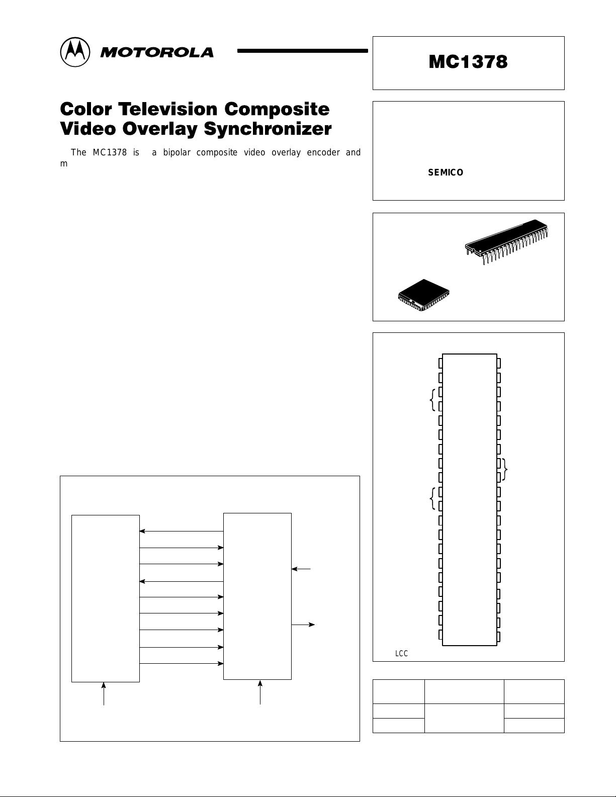
Figure 1. Simplified Application
36MHz Master Clock
H Sync
Video
System
525/60
625/50
3.58/4.43MHz
Vert/Comp Sync
Red
Green
Blue
Video Enable
Local/Remote
MC1378
PAL/
NTSC
Remote
Video
Composite
Overplayed
Video
COLOR TELEVISION
COMPOSITE VIDEO OVERLAY
SYNCHRONIZER
SEMICONDUCTOR
TECHNICAL DATA
P SUFFIX
PLASTIC PACKAGE
CASE 711
40
1
FN SUFFIX
PLASTIC PACKAGE
1
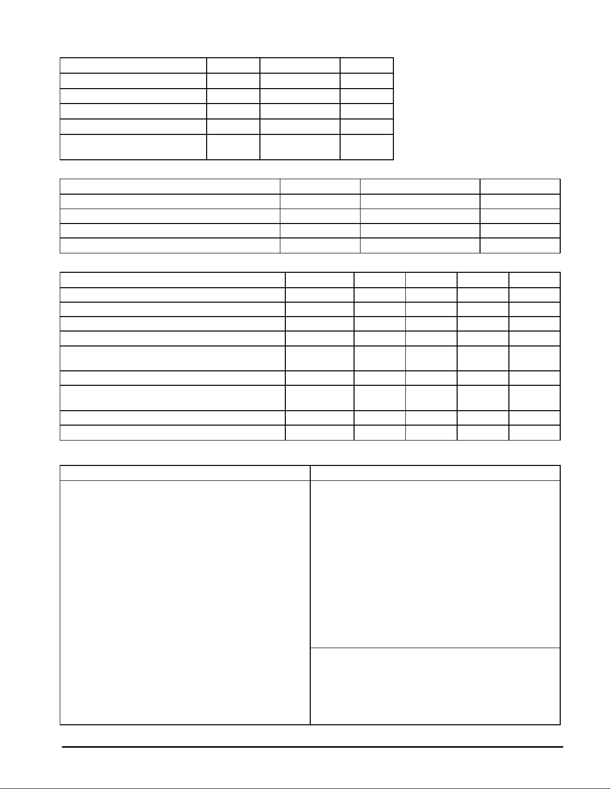
PIN CONNECTIONS
Local/Rem.
H. PLL Filter
H. VCO
Burst Gate Out
PAL/NTSC Mode
Ground
3.58/4.43 In
Chroma PLL Filter
Chroma VCO
R–Y Clamp
B–Y Clamp
R Input
G Input
B Input
–Y Output
Chroma Out
Loc. Vid. Clamp
Chroma In
* ( ) PLCC Pin Assignments
{
{
1 (1)
2 (2)
3 (3)
4 (4)
5 (5)
6 (7)
7 (8)
8 (9)
9 (10)
10 (11)
11 (12)
12 (13)
13 (14)
14 (15)
15 (16)
16 (18)
17 (19)
18 (20)
19 (21)
20 (22)
ORDERING INFORMATION
Operating
Device
MC1378P
MC1378FN
Temperature Range
TA = 0° to +70°C
CASE 777
(PLCC–44)
(44) 40
(43) 39
(42) 38
(41) 37
(40) 36
(38) 35
(37) 34
(36) 33
(35) 32
(34) 31
(33) 30
(32) 29
(31) 28
(30) 27
(29) 26
(27) 25
(26) 24
(25) 23
(24) 22
(23) 21
H. Sync In
Comp. Sync Out
V. Out/Sync In
Clock PLL Filter
Clock V
CC
Clock Output
Clock Ground
Clock VCO
}
Killer Filter
Quad. Loop Filter
PAL Indent. Cap
V
CC
Comp. Vid. Out
Ground
Overlay Enable
Rem. Vid. In
ACC Filter
–Y Input
Rem. Vid. Clamp
Package
Plastic DIP
PLCC–44
MOTOROLA ANALOG IC DEVICE DATA
Motorola, Inc. 1996 Rev 0
1
MC1378
MAXIMUM RATINGS
Rating Symbol Value Unit
Supply Voltage V
Operating Temperature T
Storage Temperature T
Junction Temperature T
Power Dissipation, Package
Derate above 25°C
CC
A
stg
J(max)
P
D
RECOMMENDED OPERATING CONDITIONS
Condition Pin Value Unit
Supply Voltage 28, 36 5.4 ± 0.25 Vdc
RGB Input for 100% Saturation 14, 15, 16 1.0 Vpp
Color Oscillator Input Level 8 0.5 Vpp
Video Input, Positive 24 1.0 Vpp
6.0 Vdc
0 to +70 °C
–65 to +150 °C
150 °C
1.25
10
W
mW/°C
ELECTRICAL CHARACTERISTICS (V
Characteristics
Supply Current 28, 36 – 100 – mAdc
Video Output, Open Circuit, Positive 27 – 2.0 9.4 V
Modulation Angle (R – Y) to (B – Y) – 87 90 93 Degrees
RGB Input Impedance 14, 15, 16 – 10 – kΩ
Local/Remote Switch (TTL) High
Horizontal Sync Input, Negative Going (TTL) 40 – 4.3 – V
Vertical Sync Output, Negative Going,
Remote Mode (TTL)
Composite Sync Output, Negative Going (TTL) 39 – 4.3 – V
Burst Gate Output, Positive Going (TTL) 5 – 4.3 – V
= 5.0 V, TA = 25°C, circuit of Figure 4 or 5)
CC
Pin Min Typ Max Unit
Low
1 – Remote
38 – 4.3 – V
pp
– –
Local
pp
pp
pp
pp
Description of Operation – Refer to Figures 3, 4
Remote Mode Local Mode
The incoming remote video signal (Pin 24) supplies all
synchronizing information. A discussion of the function of the
phase detectors helps to clarify the lockup method:
PD1 locks the internally counted–down 4 MHz horizontal VCO
to the incoming horizontal sync. It is fast acting, to follow
VCR source fluctuations.
PD2 locks the 36 MHz clock VCO, which is divided down by
the video system, to the divided down horizontal VCO.
PD3 is a gated phase detector which locks the 14 MHz crystal
oscillator, divided by 4, to the incoming color burst.
PD4 controls an internal phase shifter to assure that the
outgoing color burst is the same phase as incoming burst
at PD3.
PD5 not used in REMOTE MODE
Vertical lock is obtained by continuously resetting the sync
generator in the video system with separated vertical sync from the
MC1378, Pin 38. This signal is TTL level vertical block sync,
negative going. The horizontal sync from the video system to Pin 40
is also TTL level with sync negative going. The local/remote switch,
Pin 1, is in local mode when grounded, remote mode when taken
to 5.0 V . The overlay control, Pin 25, has an analog characteristic,
centered about 1.0 V , which allows fading from local to remote.
The MC1378 and a video system combine to provide a fully
synchronized standard signal source. In this case, composite sync
must be supplied by the video system or other time base system.
In the MC1378 the phase detectors operate as follows:
PD1 locks the internally counted–down 4 MHz horizontal VCO
to a Horizontal Sync signal (at Pin 40) from the video
system (counted down from 36 MHz)
PD2 not used in LOCAL MODE.
PD3 not used in LOCAL MODE.
PD4 active, but providing an arbitrary phase shift setting
between the color oscillator and the output burst phase.
PD5 locks the 36 MHz clock VCO (which is divided down by
the video system) to the 14 MHz (crystal) color oscillator.
The 14 MHz is, therefore, the system standard in LOCAL
MODE, and is not DC controlled.
COMPOSITE VIDEO GENERATION
The color encoding at the RGB signals is done exactly as in
the MC1377. Composite chroma is looped out at Pins 18 and 20
to allow the designer to choose band shaping. Luminance is
similarly brought out (Pins 17 and 22) to permit installation of
the appropriate delay.
Composite sync output, Pin 39, and burst gate output, Pin 5,
are provided for convenience only.
2
MOTOROLA ANALOG IC DEVICE DATA
 Loading...