

Motorola MC1374P Datasheet
The MC1374 includes an FM audio modulator, sound carrier oscillator , RF
oscillator, and RF dual input modulator . It is designed to generate a TV signal
from audio and video inputs. The MC1374’s wide dynamic range and low
distortion audio make it particularly well suited for applications such as video
tape recorders, video disc players, TV games and subscription decoders.
• Single Supply, 5.0 V to 12 V
• Channel 3 or 4 Operation
• V ariable Gain RF Modulator
• Wide Dynamic Range
• Low Intermodulation Distortion
• Positive or Negative Sync
• Low Audio Distortion
• Few External Components
Order this document by MC1374/D
TV MODULATOR CIRCUIT
SEMICONDUCTOR
TECHNICAL DATA
14
1
P SUFFIX
PLASTIC PACKAGE
CASE 646
ORDERING INFORMATION
Operating
Device
MC1374P TA = 0° to +70°C Plastic DIP
Temperature Range
Package
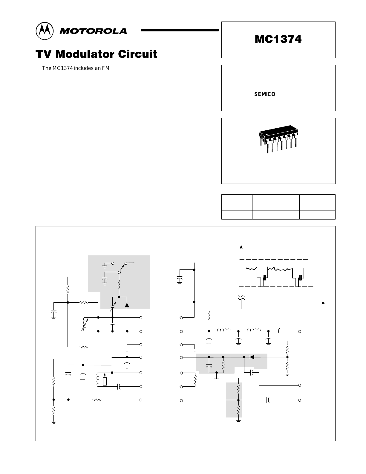
C1
0.001
R4
6.8k
R5
3.3k
+
R1
470
+
C450C3
120
L1 – 4 Turns #22, 1/4
L2 – 40 Turns, #36, 3/16
0.001
R3
470
L1
R2
470
Channel 3 4
C8
5–25
C7
C2
56
+
C14
0.01
L2
C5
0.001
R6
2.2k
″
Dia.
″
Dia.
S1
R10
10k
+
D1
MPN3404
7
6
5
4
3
2
1
Figure 1. Simplified Application
+VCC = 12V
C9
0.001
8
R7
0.22µH
Ω
U1
MC1374
75
9
C11
10
22
11
C16
12
47
R8
13
2.2k
14
Shaded Parts Optional
L3
C12
R14
56k
R12
180k
R13
30k
47
V
4
3
D2
22
C15
0.001
R9
560
R11
220
+
C6
µ
F
1
+
0.22µH
L4
1N914
+
C10
µ
F
10
C13
V
Pin 1
V
Pin
Output
Video In
Audio In
11
t
MOTOROLA ANALOG IC DEVICE DATA
Motorola, Inc. 1996 Rev 0
1
MC1374
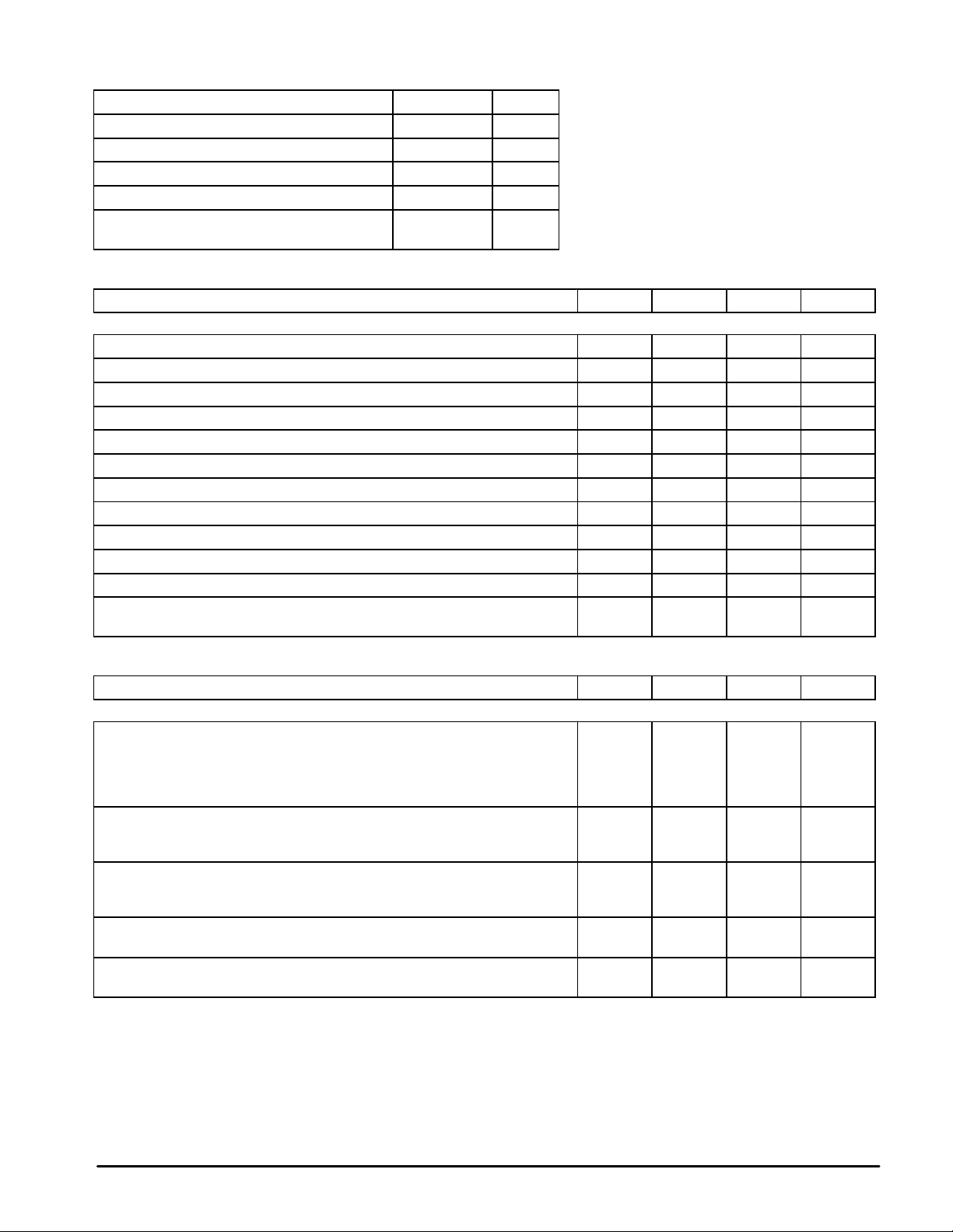
MAXIMUM RATINGS
Supply Voltage 14 Vdc
Operating Ambient Temperature Range 0 to +70 °C
Storage Temperature Range –65 to +150 °C
Junction Temperature 150 °C
Power Dissipation Package
Derate above 25°C
ELECTRICAL CHARACTERISTICS (V
AM OSCILLATOR/MODULATOR
Operating Supply Voltage 5.0 12 12 V
Supply Current (Figure 1) – 13 – mA
Video Input Dynamic Range (Sync Amplitude) 0.25 1.0 1.0 V Pk
RF Output (Pin 9, R7 = 75 Ω, No External Load) – 170 – mV pp
Carrier Suppression 36 40 – dB
Linearity (75% to 12.5% Carrier, 15 kHz to 3.58 MHz) – – 2.0 %
Differential Gain Distortion (IRE Test Signal) 5.0 7.0 10 %
Differential Phase Distortion (3.58 MHz IRE Test Signal) – 1.5 2.0 Degrees
920 kHz Beat (3.58 MHz @ 30%, 4.5 MHz @ 25%) – –57 – dB
Video Bandwidth (75 Ω Input Source) 30 – – MHz
Oscillator Frequency Range – 105 – MHz
Internal Resistance across Tank (Pin 6 to Pin 7)
Internal Capacitance across Tank (Pin 6 to Pin 7)
(TA = 25°C, unless otherwise noted.)
Rating
= 12 Vdc, TA = 25°C, fc = 67.25 MHz, Figure 4 circuit, unless otherwise noted.)
CC
Characteristics
Value Unit
1.25
10 mW/°C
W
Min Typ Max Unit
–
–
1.8
4.0
–
–
kΩ
pF
ELECTRICAL CHARACTERISTICS (T
Characteristics
FM OSCILLATOR/MODULATOR
Frequency Range of Modulator
Frequency Shift versus Temperature (Pin 14 open)
Frequency Shift versus VCC (Pin 14 open)
Output Amplitude (Pin 3 not loaded)
Output Harmonics, Unmodulated
Modulation Sensitivity 1.7 MHz
4.5 MHz
10.7 MHz
Audio Distortion (±25 kHz Deviation, Optimized Bias Pin 14)
Audio Distortion (±25 kHz Deviation, Pin 14 self biased)
Incidental AM (±25 kHz FM)
Audio Input Resistance (Pin 14 to ground)
Audio Input Capacitance (Pin 14 to ground)
Stray Tuning Capacitance (Pin 3 to ground)
Effective Oscillator Source Impedance (Pin 3 to load)
= 25°C, VCC = 12 Vdc, 4.5 MHz, Test circuit of Figure 11, unless otherwise noted.)
A
Min Typ Max Unit
14
–
–
–
–
–
–
–
–
–
–
–
–
–
–
4.5
0.2
–
900
–
0.20
0.24
0.80
0.6
1.4
2.0
6.0
5.0
5.0
2.0
14
0.3
4.0
–
–40
–
–
–
1.0
–
–
–
–
–
–
MHz
kHz/°C
kHz/V
mVpp
dB
MHz/V
%
kΩ
pF
pF
kΩ
2
MOTOROLA ANALOG IC DEVICE DATA
MC1374
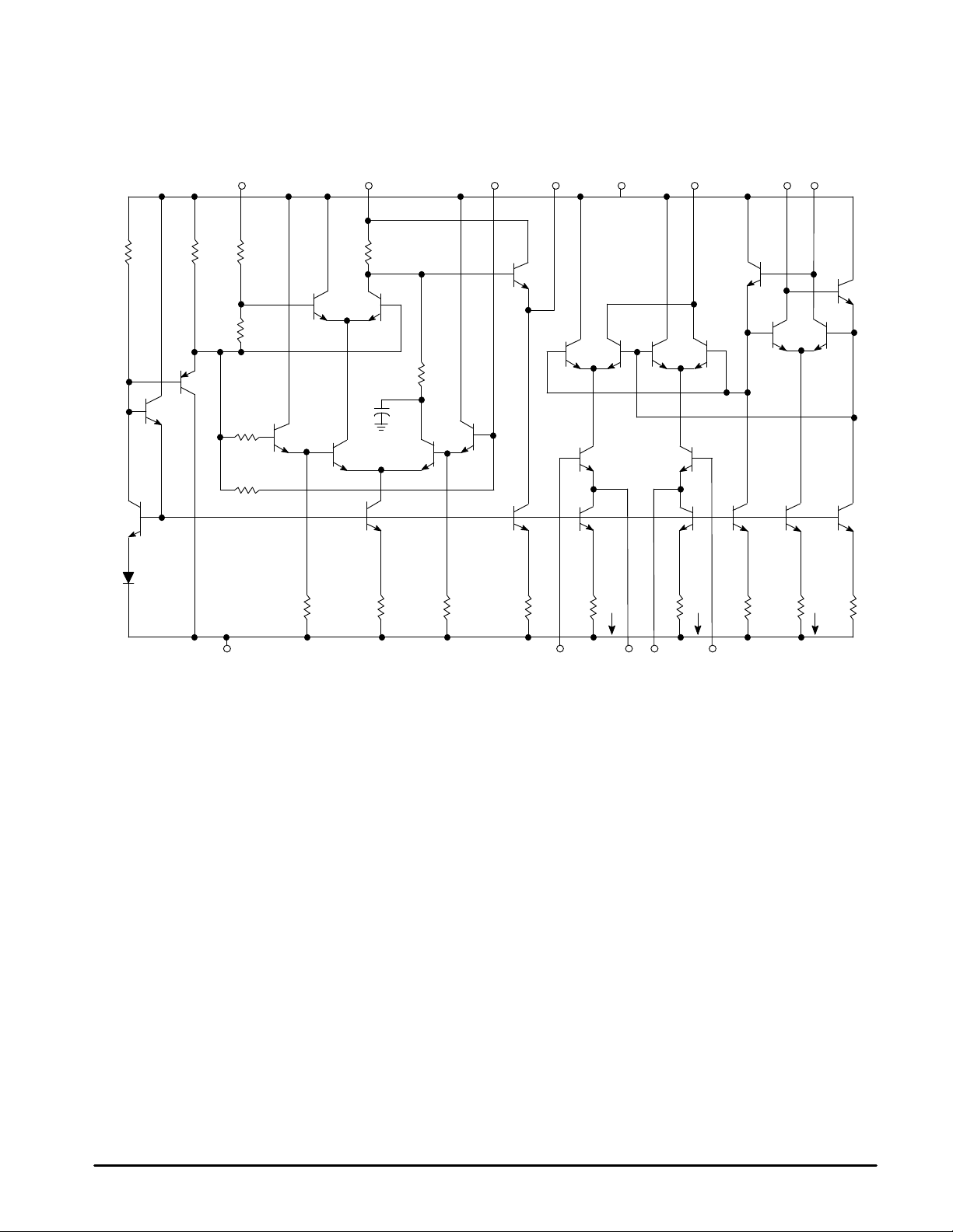
Figure 2. TV Modulator
Bias
Section
R10 R11
Q24
Q23
D1
FM Oscillator/Modulator
Audio In
14 4 3 2 8 9 7 6
R12
6.0k
R13
325
Q25
R14
Q3
R15
R1 R2 R3 R4 R5 R6 R7 R8 R9
Sound Carrier
OSC B+
R16
Q1 Q2
C1
Q4 Q5
Q26 Q27 Q8 Q9 Q16 Q17
Sound Carrier
Oscillator
Q7
Q12 Q13 Q14 Q15
R17
Q6
AM Modulator
V
CC
Q10 Q11
I = 1.15 mA1I = 1.15 mA
RF Out
1
Q21
AM Oscillator
RF Tank
Q19 Q20
2
I = 1.15 mA
Q22
Q18
5 1131211
Gnd Sound CarrierInGain Video In
GENERAL INFORMATION
The MC1374 contains an RF oscillator, RF modulator , and
a phase shift type FM modulator, arranged to permit good
printed circuit layout of a complete TV modulation system.
The RF oscillator is similar to the one used in MC1373, and is
coupled internally in the same way . Its frequency is controlled
by an external tank on Pins 6 and 7, or by a crystal circuit, and
will operate to approximately 105 MHz. The video modulator
is a balanced type as used in the well known MC1496.
Modulated sound carrier and composite video information
can be put in separately on Pins 1 and 11 to minimize
unwanted crosstalk. A single resistor on Pins 12 and 13 is
selected to set the modulator gain. The RF output at Pin 9 is
a current source which drives a load connected from Pin 9 to
V
CC.
The FM system was designed specifically for the TV
intercarrier function. For circuit economy, one phase shift
circuit was built into the ship. Still, it will operate from 1.4 MHz
to 14 MHz, low enough to be used in a cordless telephone
base station (1.76 MHz), and high enough to be used as an
FM IF test signal source (10.7 MHz). At 4.5 MHz, a deviation
of ±25 kHz can be achieved with 0.6% distortion (typical).
In the circuit above, devices Q1 through Q7 are active in
the oscillator function. Differential amplifier Q3, Q4, Q5, and
Q6 acts as a gain stage, sinking current from input section
Q1, Q2 and the phase shift network R17, C1. Input amplifier
Q1, Q2 can vary the amount of “in phase” Q4 current to be
combined with phase shifter current in load resistor R16. The
R16 voltage is applied to emitter follower Q7 which drives an
external L–C circuit. Feedback from the center of the L–C
circuit back to the base of Q6 closes the loop. As audio input
is applied which would offset the stable oscillatory phase, the
frequency changes to counteract. The input to Pin 14 can
include a dc feedback current for AFC over a limited range.
The modulated FM signal from Pin 3 is coupled to Pin 1 of
the RF modulator and is then modulated onto the AM carrier.
MOTOROLA ANALOG IC DEVICE DATA
3
 Loading...