

Motorola MC13145FTA Datasheet
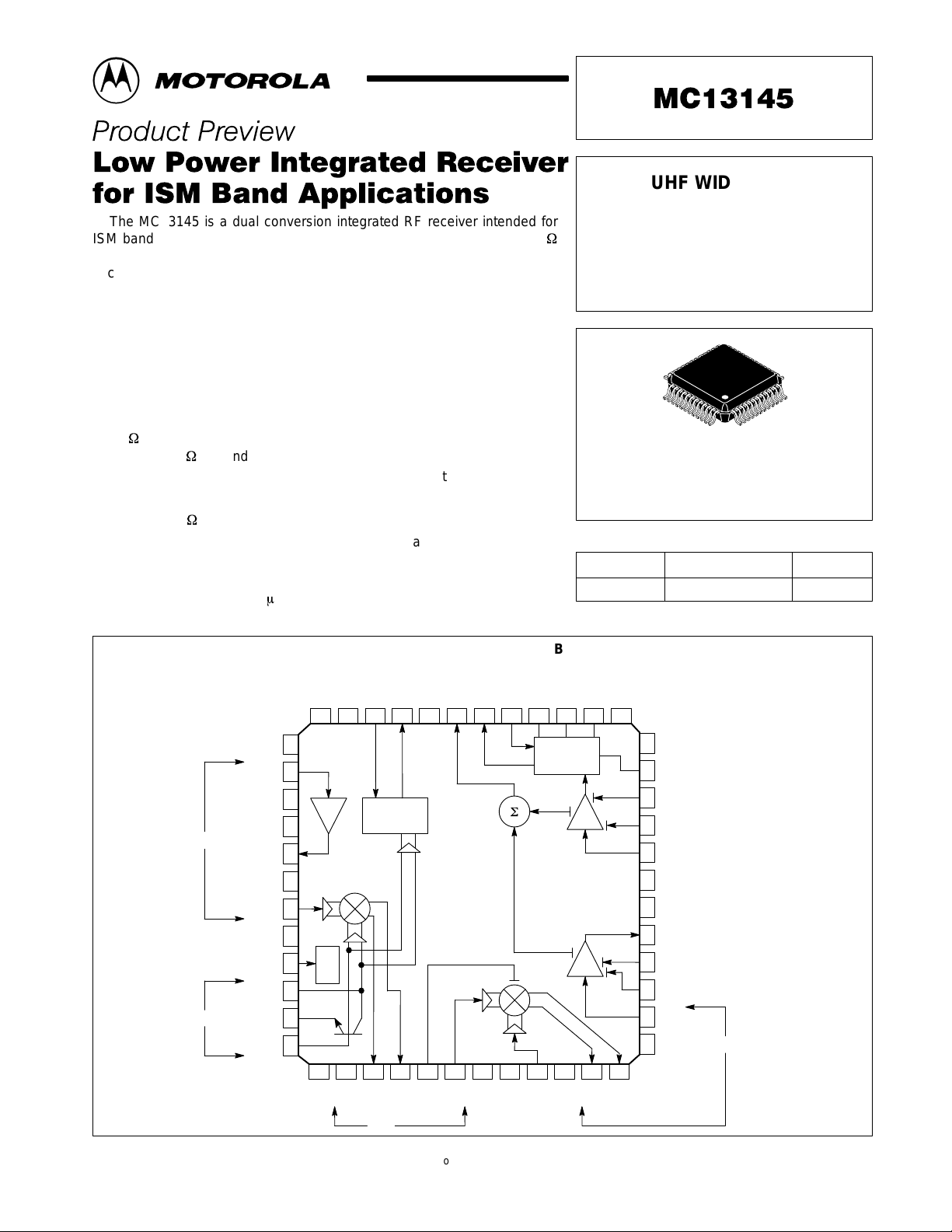
The MC13145 is a dual conversion integrated RF receiver intended for
ISM band applications. It features a Low Noise Amplifier (LNA), two 50
linear Mixers with linearity control, Voltage Controlled Oscillator (VCO),
second LO amplifier, divide by 64/65 dual modulus Prescalar, split IF
Amplifier and Limiter, RSSI output, Coilless FM/FSK Demodulator and
power down control. Together with the transmit chip (MC13146) and the
baseband chip (MC33410), a complete 900 MHz cordless phone system can
be implemented. This device may be used in applications within 2.0 GHz
since its RF bandwidth is greater than 2.4 GHz.
• Low (<1.8 dB @ 900 MHz) Noise Figure LNA with 14 dB Gain
• Externally Programmable Mixer linearity: IIP3 = 10(nom.) to +20 dBm
(Mixer1); IIP3 = 10 (nom.) to 20 dBm (Mixer2)
• 50
Mixer Input Impedance and Open Collector Output (Mixer 1 and
Mixer 2); 50 Second LO (LO2) Input Impedance
• Low Power 64/65 Dual Modulus Prescalar (MC12053 type)
• Split IF for Improved Filtering and Extended RSSI Range
• Internal 330
Terminations for 10.7 MHz Filters
• Linear Coilless FM/FSK Demodulator with Externally Programmable
Bandwidth, Center Frequency and Audio level
• 2.7 V to 6.5 V Operation, Low Current Drain (<30 mA @ 3.0 V) with
Power Down Mode (<1.0 A)
• 2.4 GHz RF , 1.0 GHz IF1 and 50 MHz IF2 Bandwidth
Order this document by MC13145/D
UHF WIDEBAND
RECEIVER SUBSYSTEM
(LNA, Mixer, VCO, Prescalar,
IF Subsystem,
Coilless Detector)
1
48
FTA SUFFIX
PLASTIC PACKAGE
CASE 932
(LQFP–48)
ORDERING INFORMATION
Device
XC13145FTA –40° to +85°C LQFP–48
Temperature Range
ESD Sensitive — Handle with Care
Package
RF
LO
V
EE
LNA In
V
EE
V
EE
LNA Out
V
EE
Mxr1In
Lin Adj1
Enable
oscC
oscE
oscB
PIN CONNECTIONS AND FUNCTIONAL BLOCK DIAGRAM
EE
VCCVCCMC
12 11 8 7 6 510 9
13
14
15
LNA
16
17
18
19
20
21
22
23
24
Control
25 26 29 30 31 3227 28
CC
V
PRSC Out
VEERSSI
/64, 65
EE
V
IF1+
IF1
IF1–
LinAdj2
2
Mxr In
Det Out
CC
V
Det Gain
EE
V
AFT
4321
Demod
33 34 35 36
LO2
AFT Buf
EE
V
Lim
IF
adj
F
IF2+
V
48
47
46
45
44
43
42
41
40
39
38
37
IF2–
V
EE
BWadj
Lim Dec2
Lim Dec1
Lim In
V
CC
V
CC
IF Out
IF Dec2
IF Dec1
IF In
V
EE
IF2
This document contains information on a product under development. Motorola
reserves the right to change or discontinue this product without notice.
MOTOROLA RF/IF DEVICE DATA
Motorola, Inc. 1998 Rev 0
1
OVERALL RECEIVER SPECIFICA TIONS
Á
Á
Á
Á
Á
Á
Á
Á
Á
Á
Á
Unit
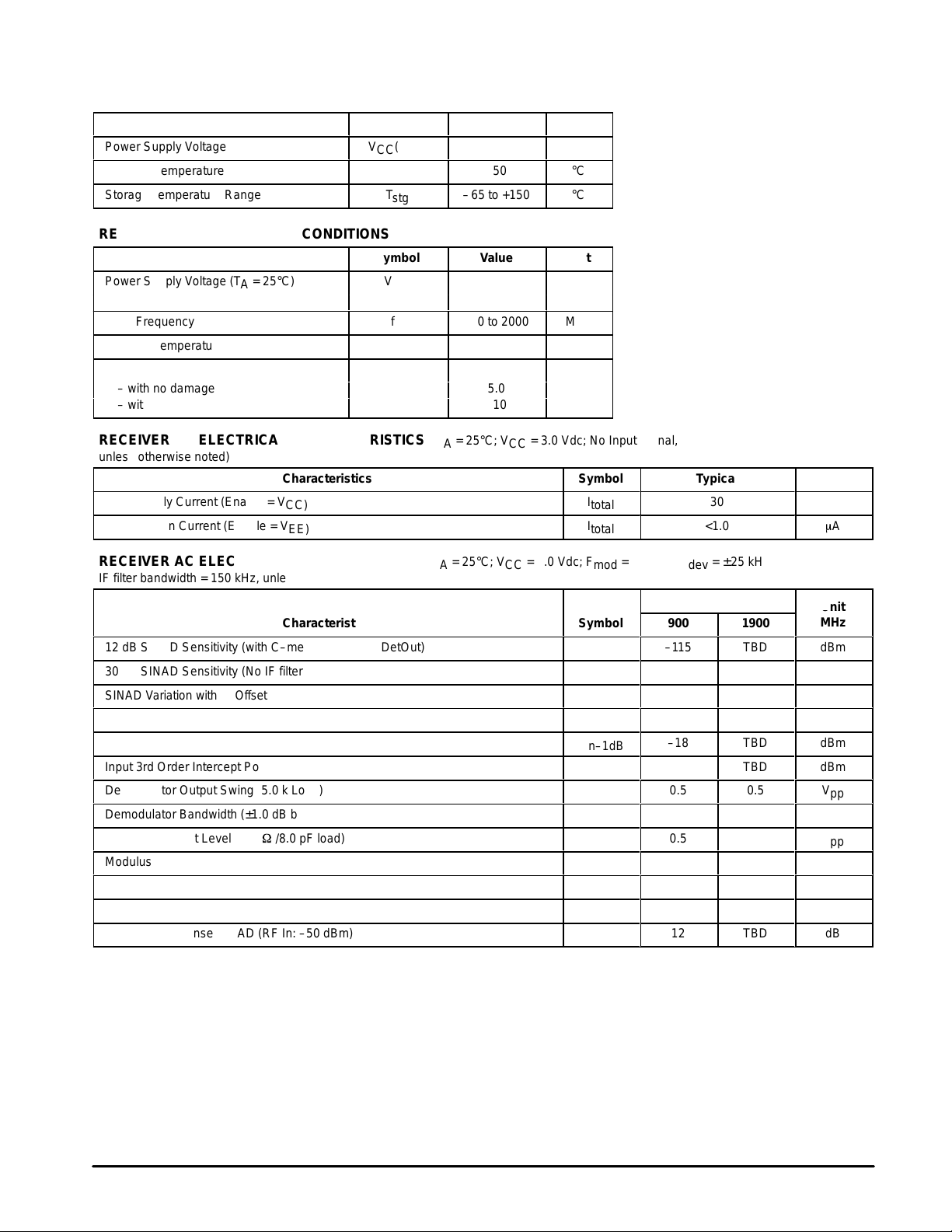
MAXIMUM RATINGS
Rating Symbol Value Unit
Power Supply Voltage
Junction Temperature
Storage Temperature Range
RECOMMENDED OPERATING CONDITIONS
Rating Symbol Value Unit
Power Supply Voltage (TA = 25°C)
Input Frequency
ББББББББББ
Ambient Temperature Range
ББББББББББ
Maximum Input Signal Level:
ББББББББББ
– with no damage
– with minor performance degradation
VCC(max)
ÁÁÁ
ÁÁÁ
ÁÁÁ
TJ(max)
T
stg
V
CC
V
EE
f
in
T
A
P
in
MC13145
7.0
150
–65 to +150
2.7 to 6.5
0
100 to 2000
ÁÁÁ
–40 to +85
ÁÁÁ
ÁÁÁÁÁÁ
5.0
–10
ÁÁ
ÁÁ
Vdc
°C
°C
Vdc
MHz
°C
dBm
RECEIVER DC ELECTRICAL CHARACTERISTICS (T
= 25°C; VCC = 3.0 Vdc; No Input Signal,
A
unless otherwise noted)
Characteristics
Total Supply Current (Enable = V
Power Down Current (Enable = V
RECEIVER AC ELECTRICAL CHARACTERISTICS (T
CC)
EE)
= 25°C; VCC = 3.0 Vdc; F
A
IF filter bandwidth = 150 kHz, unless otherwise noted)
Characteristics Symbol
12 dB SINAD Sensitivity (with C–message filter at DetOut)
30 dB SINAD Sensitivity (No IF filter distortion within ±40 kHz)
SINAD Variation with IF Offset of ±40 kHz (No IF filter distortion within ±40 kHz)
RSSI Dynamic Range
Input 1.0 dB Compression Point(Measured at IF output)
Input 3rd Order Intercept Point (Measured at IF output)
Demodulator Output Swing (5.0 k Load)
Demodulator Bandwidth (±1.0 dB bandwidth)
Prescalar Output Level (10 kW//8.0 pF load)
Modulus Control Input Level
SNR @ –30 dBm Signal Input (<25 kHz deviation;with C–Message Filter)
Total Harmonic Distortion (<25 kHz deviation;with C–Message Filter)
Spurious Response SINAD (RF In: –50 dBm)
Symbol Typical Unit
I
total
I
total
mod
P
in–1dB
IIP3
= 1.0 kHz; F
30
<1.0
= ±25 kHz;
dev
Typical
900 1900
–115
–100
5.0
80
–18
–8.0
0.5
100
0.5
0.5
50
1.0
12
TBD
TBD
TBD
TBD
TBD
TBD
0.5
100
0.5
0.5
TBD
TBD
TBD
mA
m
Unit
MHz
dBm
dBm
dB
dB
dBm
dBm
V
pp
kHz
V
pp
V
pp
dB
%
dB
A
2
MOTOROLA RF/IF DEVICE DATA
 Loading...