

Motorola MC13025D, MC13025P Datasheet
14
SEMICONDUCTOR
TECHNICAL DATA
ETR FRONT END for
C–QUAM AM STEREO
PIN CONNECTIONS
Order this document by MC13025/D
P SUFFIX
PLASTIC PACKAGE
CASE 648
16
1
D SUFFIX
PLASTIC PACKAGE
CASE 751B
(SO–16)
16
1
13
15
3
LO
Buffer
16
9
10
11
12
7
8
6
5
4
2
1
IF Amp Out
N.C. Open
Gnd
V
CLO
In
LO Output
Collector
Emitter
Base
Wideband
AGC Out
3V Ref
In
IF Amp In
Gnd
Out
In
Wideband
AGC In
V
CC
IF Amp
VCLO
4x LO
÷
4
Mixer
Wideband
AGC
(T op View)
PNP
Mixer
B
E
C
1
MOTOROLA ANALOG IC DEVICE DATA
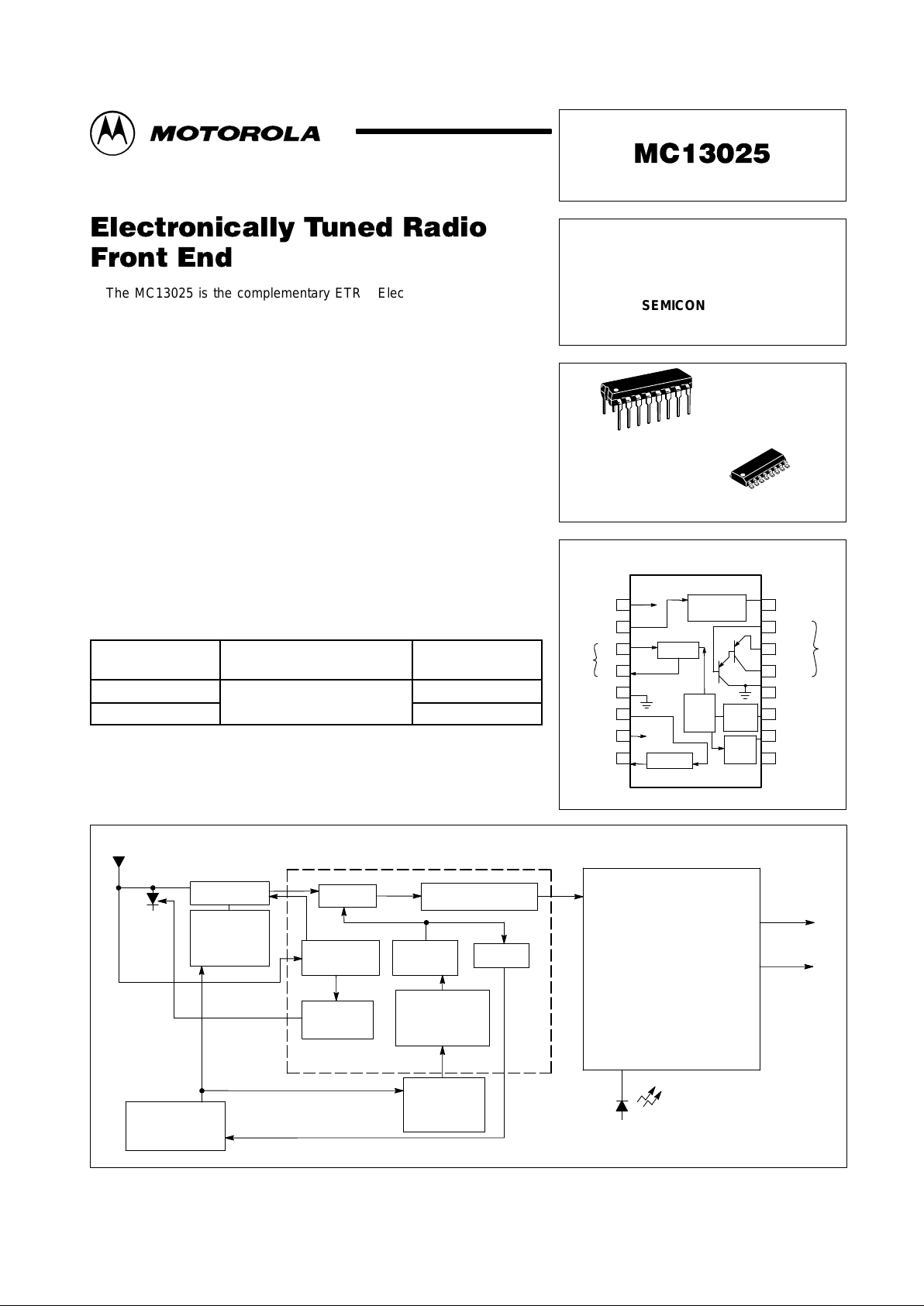
The MC13025 is the complementary ETR Electronically Tuned Radio
front–end for the second generation MC13022 C–QUAM AM stereo IF and
decoder. The MC13025 provides a high dynamic range mixer, voltage
controlled oscillator, and first IF that with the MC13022 and synthesizer form
a complete digitally controlled AM stereo tuner system. This system in turn
may drive a dual channel audio processor and high power amplifiers for car
radio or home stereo applications. Other applications include portable radio
“boom boxes”, table radios and component stereo systems.
• Operates Over a Wide Range of Supply Voltages: 6.0 V
CC
to 10 V
CC
• Wideband AGC Voltage to RF Amp for Extended Dynamic Range
• Buffered VCO Output to Frequency Synthesizer
• No External RF Amp Needed for Most Home Stereo and
Portable Radios
• IF Drive Output Matches the MC13022 for Optimum Performance
• VCO Operates at Four Times Local Oscillator Injection Frequency
ORDERING INFORMATION
Device
Operating
Temperature Range
Package
MC13025D
–
°
°
SO–16
MC13025P
T
A
= –
40° to +85°C
Plastic DIP
Simplified Block Diagram
Stereo Indicator
Right Channel
Left Channel
Variable Bandwidth IF
Amplifier with Notch Filter
and C–QUAM
AM
Stereo Decoder
MC13022
Mixer
IF Amplifier
Buffer
÷
4
Wideband
AGC
Voltage
Controlled
Oscillator
MC13025
Pin Attn.
Driver
Varactor
Tuned
Circuit
Frequency
Synthesizer
Varactor
Tuned
Circuit
RF Amplifier
Audio Out
This device contains 93 active transistors.
Motorola, Inc. 1996 Rev 0
MC13025
2
MOTOROLA ANALOG IC DEVICE DATA
MAXIMUM RATINGS
Rating Symbol Value Unit
Supply Voltage V
CC
12 Vdc
Ambient Operating Temperature T
A
–40 to +85 °C
Storage Temperature T
stg
–65 to +150 °C
Junction Temperature T
J
150 °C
Power Dissipation
Derate above 25°C
P
D
1.25
10
W
mW/°C
ELECTRICAL CHARACTERISTICS (T
A
= 25°C, 8.0 VCC test circuit as shown in Figure 2.)
Characteristics
Pin Min Typ Max Unit
Supply Current 1 7.0 8.2 10 mAdc
3.0 V Ref, Current In 7 –50 7.0 90 µAdc
IF Out DC Current 8 0.9 1.05 1.2 mAdc
Mixer DC Current Output 4 0.70 0.77 0.82 mAdc
IF Output Amplitude, RF Input
@ 1.7 MHz, 31.6 mV
8 270 330 390 mVrms
Local Oscillator Output 10 160 181 220 mVrms
Wideband AGC Pull–Down Current 16 0.5 1.0 1.5 mAdc
PNP Darlington (DC Beta @ 5.0 mA IE) 1000 2500 –
PNP Darlington Collector Leakage (VE = VB = 8.0 V) 13 –0.13 –0.06 – µAdc
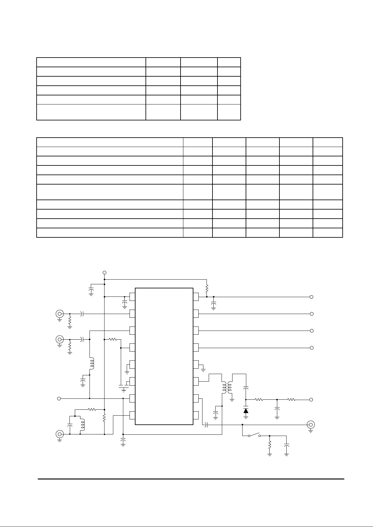
Figure 1. Test Circuit
MVAM125
Load
10 k 100
LO
Osc
Tune
1.0 k22 k
0.01
0.01
43
61
Toko
A119ANS–10287RS
430
PNP Collector
PNP Emitter
PNP Base
WB Out
47 k
0.01
NC
LO
(4x) V
CLO
Gnd
PNP
Coll
PNP
Emit
PNP
Base
Wideband
AGC Out
V
CC
Wideband
AGC In
Mixer In
Mixer Out
Gnd
0.01
V
CC
10
µ
F
1.8 k
0.01
50
WB In
Mix In
0.01
50
T oko 126ANS–7594HM
0.01
3.0 V
SFG450E
IF In
Ref
In
IF Out
10
µ
F
3.3 k
1.0 mH
510
120
IF Out
9
10
11
12
13
14
15
16
8
7
6
5
4
3
2
1
LO
3.0
mH
0.1
 Loading...