

Motorola MC13022AP Datasheet
The MC13022A is designed for home and automotive AM stereo radio
applications. The circuits and functions included in the design allow
implementation of a full–featured C–QUAM AM stereo radio with relatively
few, inexpensive external parts. It is available in either 28–lead DIP or EIAJ
compatible wide–bodied 28–lead SOIC. Functionally, the MC13022A and
MC13022 are very similar. The MC13022A has 10 dB more audio output and
a CMOS compatible logic level output (Pin 15) for stop sense. The stop
sense/AGC function has been internally connected to the output notch filter
control.
• Operation from 6.0 V to 10 V Supply with Current Drain of 20 mA Typ
• IF Amplifier with Two Speed AGC
• Post Detection Filters that Allow Automatic Adjustable Audio Bandwidth
Control and Notch Filtering (9.0 or 10 kHz)
• Signal Quality Controlled Stereo Blend and Noise Reduction
• Noise and Co–Channel Discriminating Stop–On–Station
• Signal Strength Indicator Output for Stop Sense and/or Meter Drive
• Signal Strength Controlled IF and Audio Bandwidth
• Noise Immune Pilot Detector Needs no Precision Filter Components
• MC13025 Complementary Electronically Tuned Radio Front End
• CMOS Compatible Driver for Stop Sense
C–QUAM is a registered trademark of Motorola, Inc.
The purchase of the Motorola C–QUAMAM Stereo Decoder does not carry with such purchase any license by implication, estoppel or otherwise, under any patent rights of Motorola
or others covering any combination of this decoder with other elements including use in a
radio receiver. Upon application by an interested party, licenses are available from Motorola
on its patents applicable to AM Stereo radio receivers.
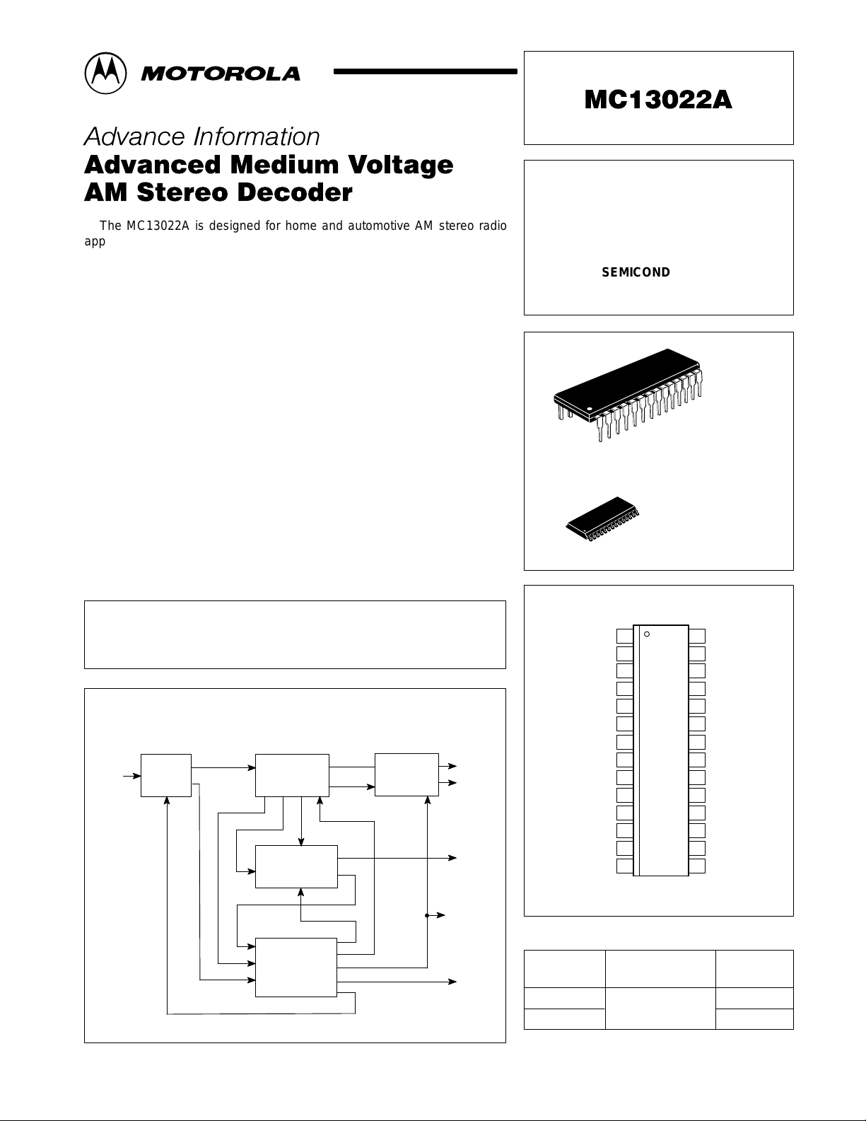
Simplified Application
θ
,
Left Audio
Right Audio
Pilot Lamp
Signal
Strength
Control of
Audio Filters
CMOS
(Logic)
450 kHz
Low–Level
IF
IF Amp
AGC
IF
Decoder
I
Q
Y es/No
Level
Fast AGC Control
Pilot
Detector
Signal
Quality
Detector
L
R
Blend, COS
Post Det
Filter
Fast–Lock
Conrol
Order this document by MC13022A/D
C–QUAM ADVANCED
MEDIUM VOLTAGE
AM STEREO DECODER
SEMICONDUCTOR
TECHNICAL DATA
28
28
Env Det
Decoder Input
AGC
IF Input
Filtered Left Out
Left Notch In
Feedback
Unfiltered L
Unfiltered R
Feedback
Right Notch In
Filtered Right Out
ORDERING INFORMATION
Device
MC13022AP
MC13022ADW
1
1
PIN CONNECTIONS
128
2
Ref
3
4
5
SS
6
722
8
9
10
out
11
out
12
13
14
Temperature Range
TA = – 40° to +85°C
PLASTIC PACKAGE
PLASTIC PACKAGE
(Top View)
Operating
P SUFFIX
CASE 710
DW SUFFIX
CASE 751F
(SO–28L)
I Det
27
L–R Det
26
Q Out
25
V
CC
24
Loop Filter
23
Blend
GND
21
Stereo Lamp
20
Osc Feedback
19
Osc In
18
Pilot Det In
17
I Pilot
16
Q Pilot
15
CMOS SS Out
Package
Plastic Power
SO–28L
This document contains information on a new product. Specifications and information herein
are subject to change without notice.
MOTOROLA ANALOG IC DEVICE DATA
Motorola, Inc. 1996 Rev 1
1
MC13022A
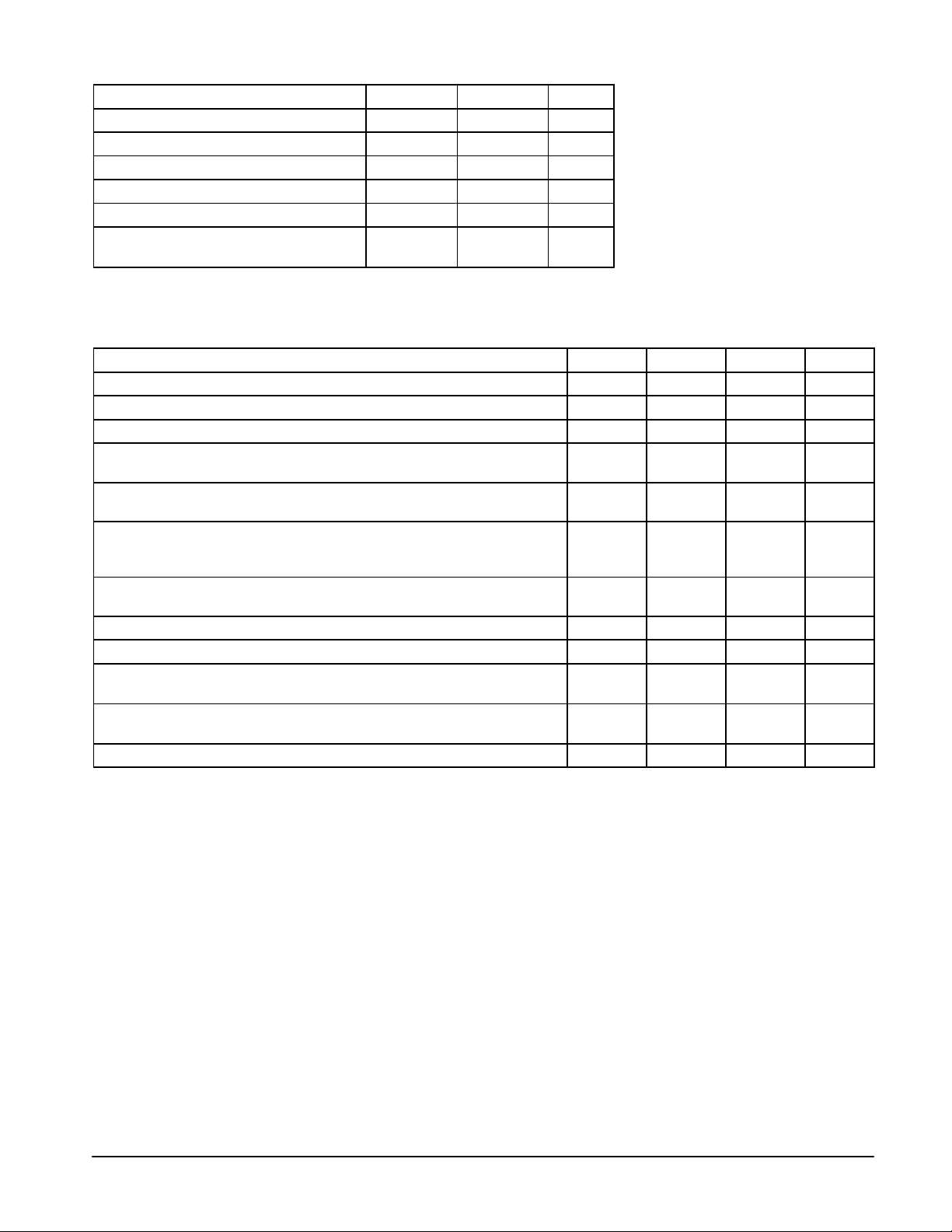
MAXIMUM RATINGS
Rating Symbol Value Unit
Power Supply Input Voltage V
Stereo Indicator Lamp Current (Pin 21) – 30 mAdc
Operating Ambient Temperature T
Storage Temperature Range T
Operating Junction Temperature T
Power Dissipation
Derate above 25°C
NOTE: ESD data available upon request.
CC
A
stg
J(max)
P
D
12 Vdc
–40 to +85 °C
–65 to +150 °C
150 °C
1.25
10
mW/°C
W
ELECTRICAL CHARACTERISTICS (V
Characteristic
Power Supply Operating Range 6.0 8.0 10 Vdc
Supply Line Current Drain (Pin 25) 10 20 25 mAdc
Minimum Input Signal Level, Unmodulated for Full Operation (Pin 5) – 5.0 – mVrms
Audio Output Level, 50% Modulation, L only or R only (Pins 10, 11) 290 400 530 mVrms
Stereo
Audio Output Level, 50% Modulation (Pins 10, 11) 140 200 265 mVrms
Monaural
Output THD, 50% Modulation %
Monaural – 0.3 0.8
Stereo – 0.5 1.6
Channel Separation, L only or R only, 50% Modulation 22 35 – dB
Stereo
Pilot Acquisition Time Following Blend Reset to 0.3 Vdc – – 600 ms
Audio Output Impedance at 1.0 kHz (Pins 7, 14) – 300 – Ω
Stereo Indicator Lamp Pin
Saturation Voltage at 3.0 mA Load Current (V
Stereo Indicator Lamp Pin
Leakage Current (Pin 21)
Oscillator Capture Range – ±3.0 – kHz
= 8.0 V, TA = 25°C, Test Circuit of Figure NO TAG, unless otherwise noted.)
CC
Min Typ Max Unit
– – 200 mVdc
– – 1.0 µAdc
sat
Pin 21)
2
MOTOROLA ANALOG IC DEVICE DATA

MC13022A
Figure 1. T est Circuit
From
Tuning System
V
CC
LED
3.0 k
Osc
Fbk
.001
3.9 k
T1
OscInPilot Det
VCO
51
Input
0.33+0.68
10 µF
+
PilotIPilot
Pilot
Detector
0.47
2.2 k
0.001
0.001
I
Det
L–R
DetQOut
28 27 26 25 24 23 22 21 20 19 18 17 15
Decoder
0.001
V
CC
µ
F 20 µF
47
+
Loop
Blend Gnd
Filt
+
Signal
Quality
Detector
Stereo
Lamp
Logic V
CC
(5.0 V)
47 k
T o CMOS
Logic
Stop
Q
16
Sense
Gain–Controlled L–R
Envelope L+R
Signal
IF
Input
0.01
Strength
Output
0.01
10 k
IF Out
3.0 V
12 345 67 891011121314
Env
Decoder
Det
Input
0.001 10
Ref AGC
13 k
L2
1.0 mH
120
+
10 µF
NOTES: 1. Q1 is switched on when the Blend Pin 23 is externally held low and the signal is weak or has 110%
2.Q2 (Pin 15) is switched on when Pin 6 voltage is below 1.7 V . Q2 could then be used as a logic output
3.User is cautioned not to require more than 1.0 mA from Pin 6.
IF/AGC
+
µ
F
100 k
negative modulation. In this condition Q1 pulls Pin 6 low (0.25 to 1.3 V). At all other times, Pin 6 follows
the curve in Figure NO TAG.
to the tuning system, telling the tuning system to continue searching for a good signal.
1.0 k
Stop Sense,
SS Meter
Q1
Buffer
Filtered
Left
Output
Filter Amp
43 k
21.5 k
370 370
T1 – Ceramic Resonator muRata
T1 – CSA 3.60 MGF103
L2 – Miller 9230–92
740
43 k
L Output
Matrix
R Output
Filter Amp
740
43 k 43 k
21.5 k
370 370
1.7 V
ref
Buffer
Q2
Filtered
Right
Output
MOTOROLA ANALOG IC DEVICE DATA
3
 Loading...