

Motorola MC10137L Datasheet
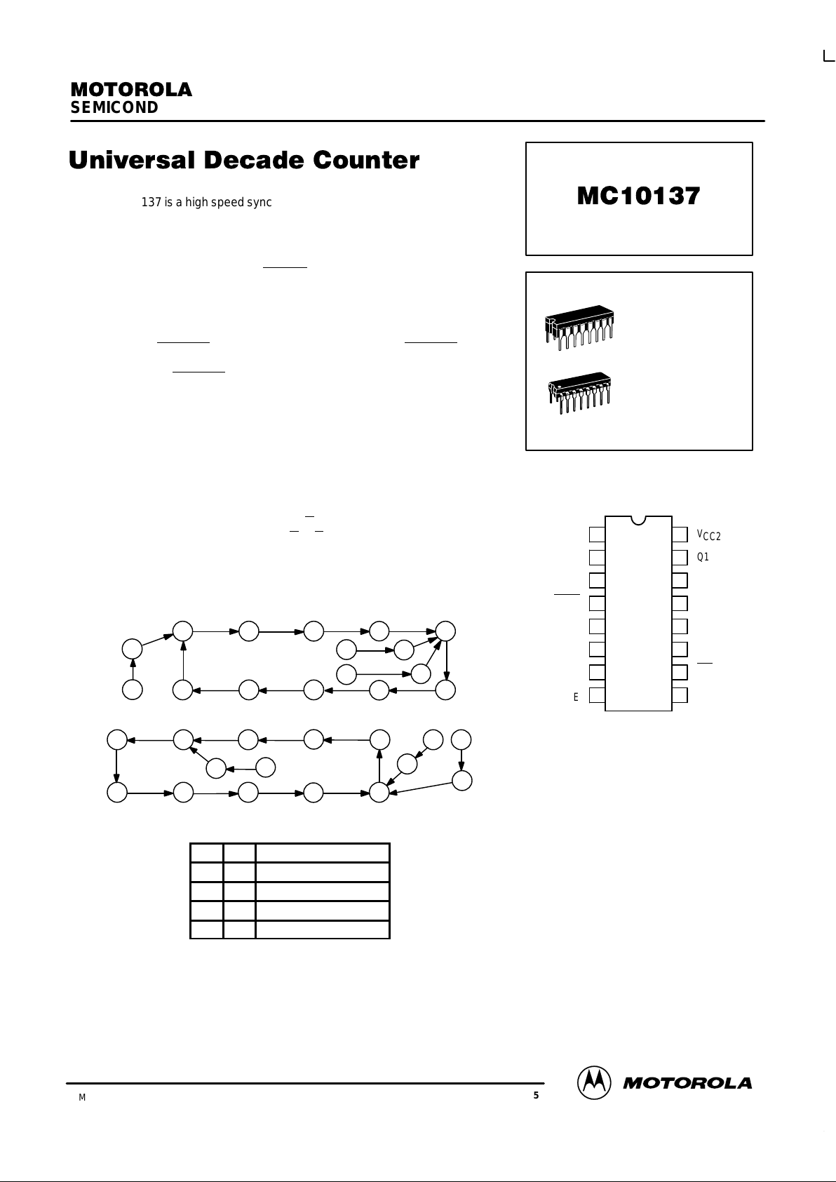
STATE DIAGRAMS
987
6
5
11
13
12
10
14
15
012
3
4
012
3
4
987
6
5
13
12
10
11
14
COUNT UP
COUNT DOWN
15
SEMICONDUCTOR TECHNICAL DATA
3–35
REV 5
Motorola, Inc. 1996
3/93
The MC10137 is a high speed synchronous counter that can count up, down,
preset, or stop count at frequencies exceeding 100 MHz. The flexibility of this
device allows the designer to use one basic counter for most applications. The
synchronous count feature makes the MC10137 suitable for either computers
or instrumentation.
Three control lines (S1, S2, and Carry In
) determine the operation mode of
the counter. Lines S1 and S2 determine one of four operations; preset
(program), increment (count up), decrement (count down), or hold (stop count).
Note that in the preset mode a clock pulse is necessary to load the counter, and
the information present on the data inputs (D0, D1, D2, and D3) will be entered
into the counter. Carry Out
goes low on the terminal count. The Carry Out on the
MC10137 is partially decoded from Q1 and Q2 directly, so in the preset mode
the condition of the Carry Out
after the Clock’s positive excursion will depend on
the condition of Q1 and/or Q2. The counter changes state only on the positive
going edge of the clock. Any other input may change at any time except during
the positive transition of the clock. The sequence for counting out of improper
states is as shown in the State Diagrams.
PD= 625 mW typ/pkg (No Load)
f
count
= 150 MHz typ
tpd= 3.3 ns typ (C–Q)
= 7.0 ns typ (C–C
out
)
= 5.0 ns typ (C
in–Cout
)
FUNCTION SELECT TABLE
S1 S2 Operating Mode
L L Preset (Program)
L H Increment (Count Up)
H L Decrement (Count Down)
H H Hold (Stop Count)
PIN ASSIGNMENT
V
CC1
2
3
C
OUT
D3
D2
S2
V
EE
V
CC2
Q1
Q0
C
D0
D1
C
IN
S1
16
15
14
13
12
11
10
9
1
2
3
4
5
6
7
8
L SUFFIX
CERAMIC PACKAGE
CASE 620–10
P SUFFIX
PLASTIC PACKAGE
CASE 648–08

MC10137
MOTOROLA MECL Data
DL122 — Rev 6
3–36
LOGIC DIAGRAM
NOTE: Flip–flops will toggle when all T inputs are low.
V
CC1
= PIN 1
V
CC2
= PIN 16
VEE= PIN 8
Q2
K
T
J
T
J
T T
Q3
T
Q3
Q1
Q1
T
T
C
J
C
T
C
Q0
S1 9
S2 7
Carry In
10
13
Clock
12 D0
14 Q0
11 D1 15 Q1
6D2
2Q2
5D3
3Q3
4 Carry Out
T
C
Q0
T
Q2
J
T
SEQUENTIAL TRUTH TABLE*
INPUTS OUTPUTS
S1 S2 D0 D1 D2 D3
Carry
In
Clock
**
Q0 Q1 Q2 Q3
Carry
Out
L L H H H L X H H H H L H
L H X X X X L H L L L H H
L H X X X X L H H L L H L
L H X X X X L H L L L L H
L H X X X X L H H L L L H
L H X X X X H L H L L L H
L H X X X X H H H L L L H
H H X X X X X H H L L L H
L L H H L L X H H H L L H
H L X X X X L H L H L L H
H L X X X X L H H L L L H
H L X X X X L H L L L L L
* Truth table shows logic states assuming inputs vary in sequence shown from top to bottom.
** A clock H is defined as a clock input transition from a low to a high logic level.
 Loading...