

Page 1
Rev. A
Grant K.
(c) 2011
Page 2

68000 Motherboard User’s Manual Rev. A
Page 2 of 54
TABLE OF CONTENTS
1 INTRODUC TION .................................... ..... ..... ..... ..... .. 4
2 DESIGN MOTIVATION .......... ..... ..... ..... ..... ..... ..... .......... 4
3 DESIGN INSPIRAT ION ......... ..... ..... ..... ..... ..... ..... .......... 4
4 WHAT IS A COM PUTER? . ..... ..... ..... ............................... 7
5 THE MB6 8K-100 COMPUTER .... ..... ..... ..... ..... ..... .......... 13
5.1 MB 68k-100 Spe c i fication . ........... . ........... . ........... . ........... . .......13
5.2 Wh at’s What an d Where Is It ........ ............ ............ . ........... . .....15
6 ARCHITECTURAL O VERVIEW ............................. ..... ..... . 15
6.1 Basic Block Lev e l D e scription .... . ........... . ........... . ............ ........16
6.2 Glimpse of th e 68 0 0 0 ..... . ........... . ........... . ........... . ........... . ........18
6.3 Bus Architect u re o f the 68000 ........... . ........... . ........... . ........... . 1 8
6.4 Bus Control Sig n a l T i ming ......... . ........... . ........... . ........... . .........19
6.4.1 Regular Bu s Cy cle Termination ......... ............ . ........... . ........... 1 9
6.4.2 Bus Ter min a t io n i nto a 6800 Bu s C ycle .... . ........... . ........... . ....22
7 CIRCUIT DESCRIPTION ..................................... ..... ..... 22
7.1 Power Input ..... . ........... . ............ ............ ............ ............ . ........22
7.1.1 Voltage Regu l a t ion ...... . ........... . ........... . ........... . ........... . .......23
7.1.2 Active Rev e r se d Connection P r o t e ction .. . ........... . ........... . ....23
7.1.3 Discrete Vo l t a g e Supervisor .... . ........... . ........... . ............ .......23
7.2 The 68000 Mi cr o p r o ce ssor .. ........... . ........... . ........... . ........... . ....24
7.3 The ‘Pintercept’ H e a ders .......... . ........... . ........... . ........... . .........24
7.4 Indicators ....... . ........... . ........... . ........... . ........... . ........... . ..........2 4
7.5 The Syste m C lo c k .......... . ........... . ........... . ........... . ........... . .........25
7.6 External Run C o n t ro l ..... ............ ............ . ........... . ........... . ........27
7.7 Reset Pulse Gene r a t or ......... . ........... . ........... . ........... . ........... . ..27
7.8 The Start Ve cto r Se l ector (SVS) .......... . ........... . ........... . ........... . 2 8
7.9 Address Spac e M a pping .. ............ ............ ............ ............ . .......29
7.10 Data Strobed Fl o w Logic . ........... . ............ ............ ............ . .....30
7.11 Bus Cycle Ter mi n a t i on . ........... . ........... . ........... . ........... . .........30
7.11.1 Bus Ter min a t io n with Auto /DTA C K ....... . ........... . ............ .....31
7.11.2 Bus Ter min a t io n with /VPA ...... . ........... . ........... . ........... . ......31
7.11.3 Bus Ter min a t io n with /BERR ...... . ........... . ........... . ........... . ....31
7.11.4 Wait State Gen erator . ........... . ........... . ........... . ........... . ........32
7.12 On-Board Perip h e r a ls . . ........... . ........... . ........... . ........... . .........32
7.12.1 Interrupt Enab le Register ......... ............ . ........... . ........... . ....33
7.12.2 The Clock Sy n chro nization Re g i s t e r ..... . ........... . ........... . .....33
7.12.2.1 On-Board Interrupt Logic Level..................................................... 34
7.12.2.2 The Hardware Entropy Generator .................................................. 34
7.12.2.3 On-Board Digital Input Interface .................................................. 36
Page 3

68000 Motherboard User’s Manual Rev. A
Page 3 of 54
7.12.3 On-Board Ou t p u t Latch ........... . ........... . ........... . ........... . .......37
7.13 Interrupt Log ic .......... . ........... . ........... . ........... . ........... . ..........3 7
7.14 On-Board Me m o r y Banks 0/1 ...... . ........... . ............ ............ .....38
7.15 Sta ck Interfa c e ........... . ........... . ........... . ........... . ............ ........39
7.15.1 Stack Interf a ce C onnector s ...... . ........... . ........... . ........... . ....39
7.15.2 Mounting H o l e s .......... . ........... . ........... . ............ ............ .......41
7.16 Quick Jumper R e f e r e n ce . . ........... . ........... . ........... . ........... . .....43
8 THE SOFT ER SIDE ............ ..... ..... ..... ..... ..... ..... ............ 46
8.1 Software Devel o p ment Tools ....... ............ . ........... . ........... . ......46
8.1.1 m68k-el f ....... . ........... . ........... . ........... . ........... . ........... . .........46
8.1.2 EASy68K ...... . ........... . ........... . ........... . ........... . ........... . ........... 4 7
8.2 MB 68k-100 Sof t ware Example s ...... ............ ............ . ........... . ...47
8.3 Software Note s o n the MB68k -100 ............ . ........... . ........... . ....50
9 GETTING STARTE D...... ..... ..... ..... ..... ..... ..... .................. 51
10 TROUBLES HOOTING ...................... ..... ..... ..... ..... ..... ... 52
11 DESIGN ERRATA AND COM MENTARY ........ ..... ..... ..... ..... 52
12 PROJECT DOCUMEN T COM PENDIUM ... ..... ..... ..... ..... ..... 54
13 DOCUMENT REVISI ON HIST ORY ................ ..... ..... ..... ... 54
Page 4

68000 Motherboard User’s Manual Rev. A
Page 4 of 54
1 Intr oduction
This project was born of no less than a childhood dream. Granted this dream had long
been somewhat vague, abstract and surviving well below the threshold of any actual
attention. But the robust desire to develop a 68000 based computer had maintained an
ever-present persistence within my hobbyist heart. And finally events have coalesced
into its fruition.
The MB68k-100 single board computer offers a platform of approachable
experimentation around Motorola’s famed 68000 microprocessor. Whether inspired by
the straightforward elegance of this particular processor at its core or by a more general
interest in computer architecture overall, the MB68k-100’s design philosophy is one to
emphasize clear understanding of the system at every level. With its discrete circuit
design, commented assembly language software examples and rich engineering and
process documentation, the project is intended to offer more than direct utility as an
embedded computer. It is meant as a launching pad, bringing to fruition future
technophile dreams.
2 Desi gn Motivation
As microprocessor technology has advanced over the past decades, an evolving spectrum
of processors has emerged into the marketplace. Examples from the early days of the
technology were stiflingly simple and fraught with debilitating resource limitations and
programming bottlenecks. In contrast, the more contemporary end of this spectrum
presents the highly integrated and massively sophisticated architectures of more recent
years, where the designer grapples with hundreds of pages of product documentation and
hundreds of tiny pins to connect. But along this gradient of microprocessor technology
stands Motorola’s 68000. With an architecture that captures the straightforward
computer designs of its past, this processor is accessible to circuitry that is easily
imagined and built. Yet the 68000 is also a pioneering design in its space, offering a
clear demonstration of the future elegance of orthogonal architecture and spacious
hardware resources. The 68000 is a link, carrying the best features of both old and new
eras of processor technology.
3 Desi gn Inspiration
In an environment of routine obsolesce, the 68000’s continuing 30 year production life
span speaks to the strength of its design. Its portfolio has ranged from advancing the
state-of-the-art upon its 1979 marketplace introduction through to its present day legacy
applications. Its reign includes a generation of top-of-the-line computers and
workstations of the early 1980’s. From there, it evolved to a commanding presence in the
embedded domain of the late 80’s though to the mid 1990’s. Beyond that, its sales
continue today, buried amongst the existing infrastructure of the modern world. And its
Page 5

68000 Motherboard User’s Manual Rev. A
Page 5 of 54
contemporary incarnations, including the ColdFire and CPU32 families, maintain the
bloodline with a sustaining market share into the future.
Through its life, the 68000 has enjoyed many notable design wins. Among computers, it
was the processor of the original Macintosh systems, the Atari ST and the Commodore
Amiga, among others. Its presence was also known among UNIX workstations,
including the original Sun Microsystems and SGI systems. And it was also the heart of
renowned game consoles, such as the Sega Genesis and Neo Geo systems, as well as
many stand-alone arcade games. It found a home in an array of computer peripherals,
networking equipment and other high-end gadgetry. My own childhood laser printer
succumbed to the screwdriver, yielding a traditional 64-pin PDIP Motorola 68000 at its
core. This processor defined a generation of computing in each market it touched.
From its original design philosophy born
within Motorola of the mid to late 1970’s,
this processor was crafted with an eye
toward the future. The processor design
was conceived under no burden of
confining software backward compatibility.
This forward-looking mindset enabled the
design engineers to “break away from the
past,” as the processor’s User’s Manual
cover art asserts. The first generation
sports a 32-bit architecture, masquerading
in 16-bit hardware. Although later
descendants expanded to true 32-bit form,
the 68000’s 32-bit data and address
registers are siphoned to the outside world
through a 16-bit data bus and 24-bit address
bus. These copious data and address
register banks, each with eight 32-bit
registers, provide a spacious backdrop to
efficient and elegant software development.
To further this elegance, the instruction set
of the 68000 was designed to be orthogonal, with a highly regular structure. The
instructions had nearly identical access to all addressing modes, moving beyond the
dedicated use of specific registers for specific functions. The 68000 internally features
two parallel 16-bit Arithmetic Logic Units for the fast calculation of addresses. From this
emerges the brilliant selection of available addressing modes, including the predecrement and post-increment capabilities. The dazzling number of address modes takes
getting used to, when approaching with a background either in the primitive 8-bit devices
preceding the 68000 or the frugal RISC designs of today.
The generous selection of 14 addressing modes and impressive count of 56 instruction
types owes thanks to the 68000’s 16-bit data bus. This bus width enables a base op code
of 16-bits, rendering wide flexibility in defining the instruction’s operation. Processor
Page 6

68000 Motherboard User’s Manual Rev. A
Page 6 of 54
instructions could include additional 16-bit data fetches beyond that to further extend the
operation. For speed, the 68000 employs a Prefetch Queue, where future memory reads
are anticipated and read while the bus would otherwise be idle. This improves
performance in that data may already be available in the processor when the advancing
program operation needs it. And code execution departs from typical technology of the
day in the 68000. It executes code in one of two modes: User or Supervisor. Supervisor
mode allows access to additional operations that are prohibited in User mode. This
enforces a greater degree of security in the code execution, and also maintains separate
User and Supervisor stacks to keep the stacks from having to bare each other’s weight.
Seven levels of interrupts are recognized by the processor, where only higher levels of
priority are permitted to capture current execution. And showing true chivalry for its
power, the 68000 also offers bus arbitration, relinquishing bus mastership to share the
system with other devices upon request.
The 68000’s sophisticated design was born of its advanced implementation in silicon. A
relatively late arrival to the 16-bit processor field, Motorola’s 68000 design was able to
leverage an increased level of integration on silicon. Constructed in superior HMOS
(High Density, Short Channel MOS) technology, the pull-up device in each gate’s output
stage is a heavily doped depletion-mode field effect transistor (FET). This FET initially
operates largely as a current source rather than a simple resistor, allowing for a faster 0to-1 transition. This capability in turn translates to faster overall operation. And this
technology, with its 3.5µm feature size, also allowed a higher number of transistors to be
incorporated into the design.
Within its rumored 68,000 transistors, the 68000’s architecture receives additional benefit
from the in-depth analysis by Motorola engineering to tailor an instruction set for
optimum utility. The processor was designed with software in mind. Studying not only
the occurrence of instructions listed within software code but the frequency that they
occur in actual code execution, Motorola engineers included single instructions that fully
embody frequent functionality. An example of this is the Test Condition, Decrement and
Branch family of instructions that tests a condition, and only when false decrements a
counter. Then, only if that counter is not counted down to -1, execution takes the
specified branch. This convoluted function is useful in implementing conditional
software loops where the number of iterations is to be limited. Another example of this
highly-integrated function is the ability within the addressing mode to advance an address
register’s value, through pre-decrement and post-increment. This circumvents the typical
need within software operations on a range of memory to include a separate instruction to
advance that pointer.
Page 7
68000 Motherboard User’s Manual Rev. A
Page 7 of 54
Many earlier microprocessor
designs implemented their
instructions as sequences
defined directly in digital logic.
The 68000 offers a much richer
functionality within its
instructions through the use of
microcoding. Microcoding
defines the internal sequence to
carry out the instructions. It
does this through the use of
low-level programming
operating within the
microprocessor logic. Like the
drum pegs scrolling through a
music box, this microcoded
program controls the timing
and sequencing of various
parts of the internal
microprocessor logic to
execute the instruction. And
this idea extends further into
the use of nanocoding since
many instructions share
common functions.
Nanocoding implements a
deeper level of execution for
common sequences that appear
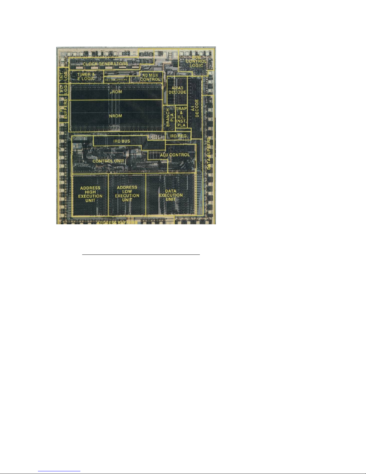
within the encoding of different instructions. A picture of the processor die is broken
down in Figure 1, indicating the function of each circuit section. Among the sections are
microcode and nanocode ROMs, control logic and, situated along the bottom, the data
Arithmetic Logic Unit and two address Arithmetic Logic Units.
The power and grace of the 68000 leaves a deep impression on the evolution of computer
and microprocessor technology. And in doing so, it leaves an impression on those with
interest in detailed hardware and software design. As both a historical milestone and a
strong example of approachable modern computing, the 68000 drives continued authority
decades after its inception.
4 What is a computer ?
Computers are programmable data processing devices. Central to their function is their
ability to move data internally, and much of the computer’s design is dedicated to this
purpose. Data in a digital computer is represented by binary digits, abbreviated as “bits.”
These bits can possess two possible states, either 0 or 1. This differs from the familiar,
base 10 numeral system, where each digit may be one of ten possibilities. The binary
Figure 1: 68000 Die Function Blocks
Source- BYTE Publications Inc.,
Design Philosophy Behind Motorola’s MC68000,
April 1983
Page 8

68000 Motherboard User’s Manual Rev. A
Page 8 of 54
numeral system is base 2, meaning that only these two digits are available. In base 2 the
significance of each digit’s place along a binary number differs by a factor of 2. When
written, binary numbers are expressed with a trailing subscript 2. Like in the base 10
system, the number 12 in binary represents a one. This is the ones place in the number,
20. But binary 102 represents 2 or 21, whereas in base 10 system 1010 represents the
number ten or 101. Binary 1002 represents 4 or 22. And 1112 is a 7, 22+21+20.
Another useful numeral system is base 16, known as hexadecimal. Hexadecimal simply
offers the advantage of grouping multiple binary digits together. Since the sixteen
possible combinations of four binary digits may be more concisely represented as a single
hexadecimal digit, hexadecimal is the preferred numeral system for its compactness.
Each hexadecimal digit represents four binary digits, and therefore two hexadecimal
digits represent a single 8-bit byte.
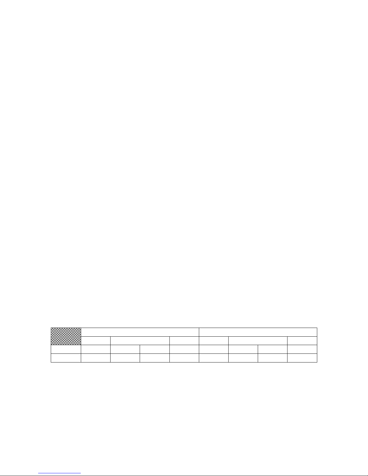
Table 1: Numeral Systems
Base
10
(Dec)
0 1 2 3 4 5 6 7 8 9 15
16
2
(Bin)
000002
00001
2
00010
2
00011
2
00100
2
00101
2
00110
2
00111
2
01000
2
01001
2
01111
2
10000
2
16
(Hex)
0016
0116
0216
0316
0416
0516
0616
0716
0816
0916
0F16
1016
As this relates to the computer, these binary digits physically correspond to the voltages
present on the signals within the computer. The digit 1 is typically represented by a high
voltage, while 0 is a low voltage. A succession of numbers over time in a digital system
appears as a signal waveform on the wire, with a separate parallel wire for each digit’s
place.
All data stored and processed in a computer can be thought of as numbers, encoded
through these voltage states. Whatever medium the data represents, it is a number
defined by parallel binary states to the computer. An image, for example, is defined
numerically as an array of values specifying how much red, green and blue to display at
each pixel location. Sound data numerically represents the amount to deflect a speaker
over time, which in turn creates corresponding sound waves. Text is defined numerically
by mapping the alphabet of possible characters to numerical codes. The message text
data is then broken into a string of characters, and the character at each position in that
string is defined by its numerical code. Using the ASCII coding standard as an example,
if 1 is added to the text data for the letter ‘A,’ it becomes a ‘B.’ If 32 is added to ‘A,’ it
becomes ‘a.’ To a computer, the world resolves to nothing more than numbers. These
numbers, though, have different meanings depending on which input or output device
they are associated. But within the computer, the numbers are simply electrical states of
the circuitry, carrying digital information.
Page 9

68000 Motherboard User’s Manual Rev. A
Page 9 of 54
Table 2: Extended ASCII Code Table
Table 3: ASCII Code Example
Character
T h e q u i c k b r o w n f o x
ASCII Code
(Hexadecimal)
54
68
65
20
71
75
69
63
6B
20
62
72
6F
77
6E
20
66
6F
78
The hardware in the computer design is responsible for the routing of the digital
information to perform the computer’s operation. For example, the computer may be
controlling multiple elements of a digital light bar output according to the states set on a
series of digital inputs. Each light would be lit according to the pattern provided on the
digital input. In this case the processor reads the input and temporarily stores the
corresponding number. It then writes that number from the temporary storage to the
output circuit. In effect, the computer receives the number presented at the input and
transfers it to the driver circuit for the output.
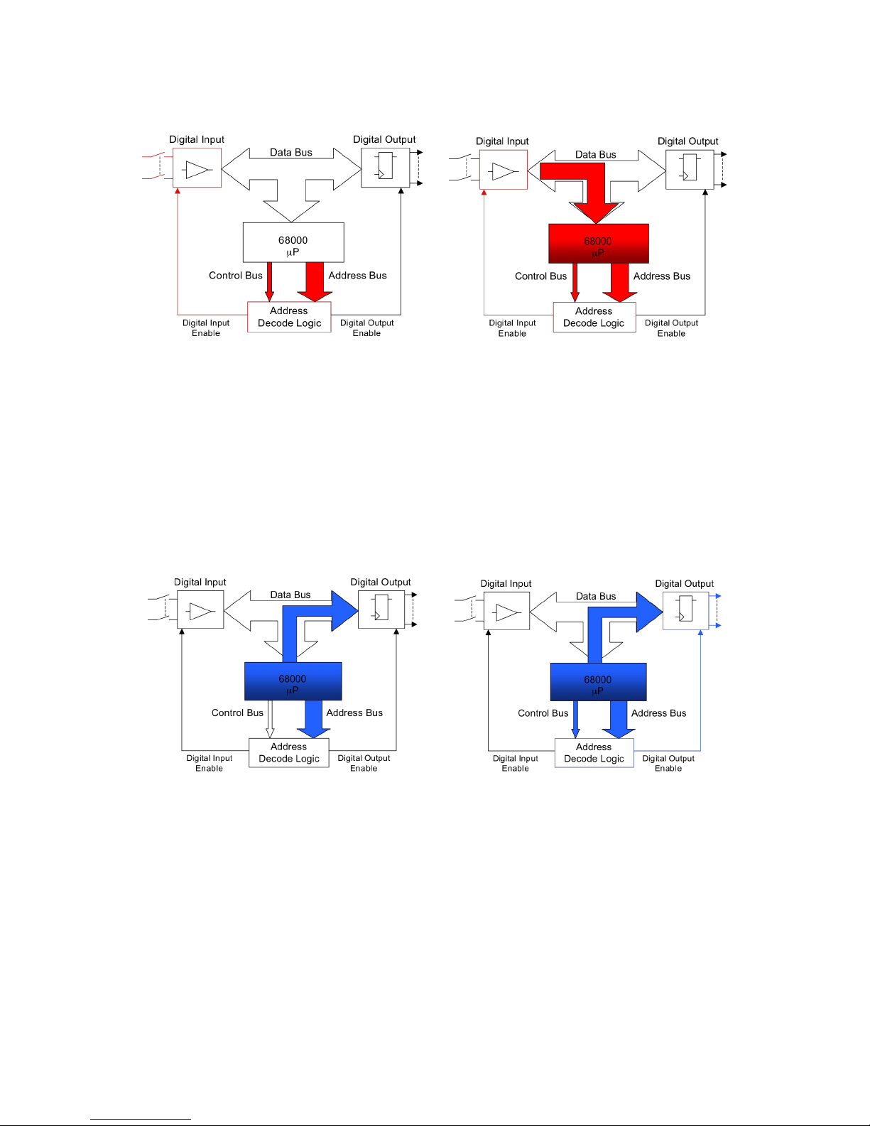
In this light bar example, shown in Figure 2 below, the read operation consists of the
microprocessor first specifying that it wants to communicate with the digital input circuit.
It does this through its address bus. The address bus is a group of separate parallel wires
that carry the binary digits of the address. And as the name suggests, the address is a
number that uniquely specifies the device with which the processor requests to
communicate. Each device available to the processor has its own unique address. The
processor also sets the Read/Write, R/W ! , signal. The state of this signal indicates
whether the operation being prepared is to be a Read or a Write. These terms are defined
in the sense of the processor: the Read reads data from the addressed device into the
processor, and conversely the Write writes data from the processor to the addressed
device. With the digital input circuit addressed and direction specified as Read, the
processor next issues the Address Strobe. This signal indicates to the system’s external
logic that the processor has finished setting up the signals for the operation, and the logic
may now begin serving the processor’s request. The system’s external decoding logic
then processes the request and signals to the addressed device that it is selected. That
device then recognizes in a Read cycle that it must report its data to the processor. The
processor and addressable device share another group of parallel connections for this
purpose, the Data Bus. After the data is established on the Data Bus by the device being
read, the external logic finally informs the microprocessor that its data is ready by
sending an acknowledgment signal to the processor. The processor then reads the data
from the Data Bus and moves on to the next operation.
Page 10
68000 Motherboard User’s Manual Rev. A
Page 10 of 54
Figure 2: Data Flow Diagrams, Read
The mechanics of the Write operation, shown in Figure 3 below, closely follow the Read.
The target device is specified by its address. But the Read/Write line here indicates a
Write operation is to be executed. The Data Bus this time is driven by the processor with
the data to be written to target. The target device is selected by the decoding logic based
on its address, and it reads the data from the processor. The cycle is then closed with the
processor receiving the acknowledge signal that the Write operation is complete. In this
example, the light bar output driver is updated by the processor. Through these steps, the
input data is transferred to the light bar output.
Figure 3: Data Flow Diagrams, Write
The devices within the computer are organized under the control of the microprocessor.
The processor addresses the device required for the current operation, completes the data
transaction with that device and then continues to the next operation. The sequence of
operations that the microprocessor follows is the software program. The program is
comprised of a series of steps that coordinate the computer’s operation. These steps are
selected from among the set of basic functions that are directly executed by the processor.
Examples of these fundamental operations include reading data from memory or an input
device, doing arithmetic operations on data, making decisions on which part of the
program to execute next, and writing data to memory or output devices, to name a few.
Page 11

68000 Motherboard User’s Manual Rev. A
Page 11 of 54
These basic functions are the microprocessor instructions. Microprocessor instructions
are the most fundamental building blocks of any program. Any program is composed of
these individual steps that are carried out directly in the computer hardware. The specific
vocabulary of these primitive program operations is defined by the particular
microprocessor in use. This vocabulary is referred to as the instruction set of the
processor. Although largely comparable in the suite of available functions, each
processor architecture’s instruction set is unique. Frequently encountered instructions
include arithmetic operations, like ADD, SUB or Boolean logic operations like AND, OR
and NOT. Program flow is controlled with conditional branch instructions that choose
the program’s next step based on data comparisons, such as ‘Branch if EQual,’ BEQ,
which only redirects program execution to the specified branch location if data compared
in a previous instruction has signaled a match. Data may be transferred between the
processor, memory and peripheral devices with the wide range of MOVE instructions.
Each processor has its own flavor of these basic functions.
Other aspects of the processor’s design are unique to its architecture. Another example
of this is the processor’s registers. Registers function as the short-term memory of the
processor, operating very fast and being directly accessible by the majority of processor
instructions. While the computer’s expansive RAM memory may be used for storing
large amounts of data being operated on, the registers keep immediate track of the
algorithm being executed. A register may be thought of as memory for a single, generalpurpose variable held within the processor. In practice, many microprocessor
instructions that make up a typical program involve performing arithmetic and
comparison operations on register data, as well as moving data between those registers
and devices of the Data Bus, such as system memory or peripheral devices.
The program snippet in Table 4 below provides an assembly language example of
microprocessor instruction coding. Assembly language is a convenient means of writing
the program’s processor instructions in an easily readable form, since the actual program
instructions exist as numerical codes. Assembly language coding is made up of the
individual instructions of the program. Each instruction defines the basic operation at
that step in the program to perform. The type of basic operation is indicated by the
instruction mnemonic, such as whether the step is to transfer data, perform an arithmetic
operation or redirect the sequence of program execution. The instruction may also
include operands to indicate on what to operate. Operands may include registers or
memory locations to be used in the operation, or numeric data to be incorporated into the
operation. The actual numerical codes interpreted by the microprocessor are referred to
as Op Codes. This snippet demonstrates some initialization functions typical at the start
of a program.
Note that labels are used in place of numerical data in some places in the assembly code
listing, such as references to ONBD_BANK0 for the starting address of on-board RAM
or ONBD_BANK0_SZ for the size of that on-board RAM. These labels allow a
symbolic representation of a number for improved readability.
Page 12

68000 Motherboard User’s Manual Rev. A
Page 12 of 54
Table 4: Initialization Example with Assembly Language
+Offset
Op Code
Instruction
Mnemonic
Source Operand
Destination
Operand
Comment
…
+00
2E7C
00004000
MOVEA.L
#(ONBD_BANK0+
ONBD_BANK0_SZ),
A7
;
supervisor
stack at
top of onboard
SRAM
+06
207C
00003C00
MOVEA.L
#(ONBD_BANK0+
ONBD_BANK0_SZONBD_SUPSTCK_SZ),
A0
+0C
4E60
MOVE.L
A0,
USP
; user
stack next
in onboard
SRAM
+0E
46FC
0000
MOVE.W
#$0000,
SR
; enter
user mode
and set up
interrupt
mask for
level 0
+12
13FC
00FE
000A0000
MOVE.B
#$FE,
ONBD_INTEN
; enable
interrupts
in
hardware
…
Page 13

68000 Motherboard User’s Manual Rev. A
Page 13 of 54
5 The MB68k-100 Computer
The MB68k-100 is a single board computer based on the Motorola 68000
microprocessor. It offers many on-board features and is highly configurable via its
multitude of jumpers and circuit access points. It also includes expansion capabilities
through its stackable daughter board interface.
5.1 MB68k-100 Specification
Table 5: MB68k-100 Specification Table
Applications:
• Real-time Embedded Control
• Education and Training
• Retro design support
• Nostalgia
• Satiation of Fervent Hobbyist
Impulse
Features:
! Full User’s Documentation seen here
! Full Process Documentation
! Extensive Access to Design Information
! Rich Example Software with Commenting
! Versatile On-Board Configurability
! Facilities for Signal Interception and Test Points
! Power Conditioning
! Supply Voltage Supervisory Function
! Indicators for Halt, Reset, Run and Power
! Multiple, Selectable Clock Sources
! Run Control with External, Power-Up and Push-Button Resets
! Selectable Reset Vector Address
! Configurable Address Decoding
! Bus Cycle Management
! Bus Error Detection
! 6800 Peripheral Compatibility
! Wait State Generation
! Hardware Entropy Generation for Random Data
! Digital Inputs
! Digital Outputs with Light Bar
! Interrupt Logic with Autovectoring
! Memory Expansion Sockets
! Stack Connectors for Expandability
! Flexible Mounting Options
Page 14

68000 Motherboard User’s Manual Rev. A
Page 14 of 54
Table 6: Recommended and Absolute Ratings Guidelines*
Rating
Condition
Value
Unit
System Clock, maximum
as tested
10
MHz
Supply Current, typ
f
CLK
= 10MHz
< 450
mA
Voltage Regulation bypassed
+5.12
VDC
Voltage Regulation,
VR120 installed with 7805
7.2
VDC
Supply Voltage, minimum
Voltage Regulation,
VR120 installed with PT5101
9.2
VDC
Voltage Regulation bypassed
5.3
VDC
Voltage Regulation,
7805 power limit
~12
VDC
Supply Voltage, maximum
Voltage Regulation,
PT5101 Input Voltage Limit
38
VDC
Operating Temperature
Lower limit by ICs,
Upper limit by Power Input
Circuitry Temperature
0 - 30
°C
Footprint
--
12” x 10”
in.
* all limits listed here are subject to engineering review per application for additional flexibility.
Page 15

68000 Motherboard User’s Manual Rev. A
Page 15 of 54
5.2 What’s W hat an d Where Is It
The overlay below maps some basic circuit sections of the MB68k-100 board.
Figure 4: MB68k-100 Block Overlay
6 Architect ural Over view
Much of the machinery of the computer design focuses on the movement of data – the
lifeblood of the computer’s operation. The computer’s microprocessor, being the
coordinator of this operation, takes part in much of this information flow. And the
arteries of this flow are the computer’s networks of buses, all managed by its control
logic.
The complex design of a computer system naturally breaks down into a collection of
modules, each serving a straightforward and simple function. Here that breakdown is
explored.
Glue
Logic
Strobe Logic
Wait State
Reset Pulse
Auto
DTACK
On-Board
Block
Block
Address
Decoder
Power Input
Reverse Prot
Osc Modules
Symmetry
Freq Div
Discrete
Osc
Clock Cfg
Voltage Reg
Page 16

68000 Motherboard User’s Manual Rev. A
Page 16 of 54
6.1 Basic Block Level Descriptio n
The computer’s basic framework builds around common electrical pathways called
buses. These are groups of parallel wires that serve to convey bits of information in
parallel throughout the computer system. Devices within the computer cooperate to share
these common pathways in order to communicate with each other. The two central
pathways are the Data and Address Buses. The Data Bus is a multiplexed medium to
carry data between devices within the computer. This data might be input from or output
to interfaces of the computer. Or it may be values accessed in the computer’s RAM or
program instruction codes that define the operation of the system from ROM.
Meanwhile, the Address Bus performs the crucial task of specifying which device is
involved in the data transfer that is taking place on the Data Bus. These transfers are
controlled by another group of signals, collectively known as the Control Bus. Though
not parallel in function, like the groups of lines in the Data and Address Buses, these
individual control signals coordinate the timing and sequencing of the data transfer that is
taking place over the course of the bus cycle. Collectively, these signals indicate the
current state of the data transfer sequence.
Figure 5 below depicts a greatly simplified (and willfully incomplete) block diagram of
the MB68k-100 motherboard’s architecture. The interrupt logic, for example, is
completely neglected. But the purpose is to give a superficial primer of the basic system
operation.
Page 17

68000 Motherboard User’s Manual Rev. A
Page 17 of 54
Figure 5: Rudimentary Architecture Block Diagram
In brief, the following conceptually outlines the basic mechanics of a bus cycle:
1. The microprocessor sets up the Address Bus, Read/Write data direction and, for a
Write operation, the Data Bus.
2. The microprocessor issues the Address Strobe signal, indicating that its outputs
are established for the bus transaction.
3. The Block Address Decoder and other Decode Logic issue the appropriate
signaling to enable the selected device.
4. Also in parallel, the Data Strobed Flow Logic issues the appropriate Read and
Write enable signals for the devices on the data bus according to the direction of
required data flow.
5. The selected device responds to participate in the bus transaction. For a Read
operation, the device places the requested data onto the Data Bus. For a Write
operation, the device receives the data that has been placed on the bus by the
microprocessor.
6. The Timing Logic, in parallel, provides sufficient time for the selected device to
respond in step 5. It then issues the acknowledgement that the transaction is
complete to the microprocessor.
Page 18

68000 Motherboard User’s Manual Rev. A
Page 18 of 54
6.2 Glimpse of the 6800 0
With greater detail coming into focus, refer to Figure 6 showing the signals of the 68000
microprocessor. The pin diagram of the DIP chip is also given in Figure 7 for reference.
The Data and Address buses are shown, as well as the various control signaling. The
functions and interactions of these signals are discussed in subsequent sections. For
deeper detail, refer to the Motorola M68000 8-/16-/32-bit Microprocessors User’s
Manual.
Figure 6: 68000 Input and Output
Signals
Figure 7: 68000 DIP Pin Diagram
6.3 Bus Architecture of the 68000
The 16-bit 68000 data bus is comprised of two conjoined 8-bit data buses. They are
referred to as the upper and lower data buses, or informally the ‘hi’ and ‘lo.’ The upper
bus carries the most significant byte data (D8-15), and the lower carries the least
significant byte (D0-D7). Since the 68000 uses a big-endian byte ordering convention,
lower addresses are associated with bytes of higher significance. That is, the high bytes
reside in the ‘hi’ device, and occupy the lower memory address. The low bytes reside in
the ‘lo’ device, and occur in the higher memory address.
Table 7: 68000 Byte Ordering Convention, Big-Endian
+0
+1
Address
Even
Odd
Significance
MSB
LSB
Data Lines
D15-D8
D7-D0
Control Line
/UDS
/LDS
Device
‘Hi’
‘Lo’
Page 19

68000 Motherboard User’s Manual Rev. A
Page 19 of 54
The 68000 specifies the device to target for the bus transfer through its 24-bit addressing
scheme. The direction of the bus transfer, being either a Read of data into the processor
or a Write from the processor, is indicated through the Read/Write signal. The state of
this signal specifies whether the bus cycle is read or write, as defined relative to the
processor. With these signals established, the Address Strobe signal, /AS, is asserted.
This signals the target device and associated bus logic that address decoding may begin.
The address bus consists only of address bits A1-A23. It carries no A0 bit to distinguish
between the odd and even byte addresses that pair to make up the 16-bit data word. The
distinction between these is made though control signals /UDS and /LDS, the upper and
lower data strobes. The /UDS signal is asserted to include the most significant byte
(MSB) at the lower address, and /LDS is asserted to include the least significant byte
(LSB) at the next adjacent address. When the operation is 16-bit, both are asserted
together. This addressing mechanism is well suited to 16-bit buses that are typically
implemented as paired 8-bit devices.
6.4 Bus Control Signal Timing
Timing is everything. When negotiating the complex flow of data traffic, careful
management of the computer’s many interconnected devices is crucial.
6.4.1
Reg ular Bus Cycle T ermination
Many microprocessors of the 1970’s operated more slowly than the peripheral and
memory devices with which they typically interfaced, so these processors simply initiated
a read or write operation at one phase in the bus cycle and unconditionally completed that
operation at a later phase in the cycle. This imposed an external limit on the processor
speed, in that the bus device must have completed its operation before the bus cycle
unconditionally closed along with the advancing system clock. The 68000, however, is
designed to decouple its clock speed from the speed of devices on the bus. It does this
through use of an acknowledge signal returned from the external logic that indicates to
the processor the completion of the bus operation. This handshaking signal is called the
Data Transfer Acknowledge. It uses negative logic and is abbreviated as /DTACK.
Motorola’s microprocessor literature refers to this means of bus control as asynchronous.
Read cycles require that the data has arrived and stabilized on the data bus before the
/DTACK signal is asserted. The requirement, therefore, is that the delay in generating
the /DTACK signal be greater than the delay in establishing the valid Read data on the
bus. This way, the processor is signaled that the data is available for it to proceed only
after the data signals are in fact available. But one exception arises here. Since /DTACK
is only examined on falling edges of the processor clock, this strict requirement is relaxed
if the two events do not straddle a falling clock edge. That is, if the data bus and
/DTACK signals are guaranteed to occur within the same clock period, with no falling
Page 20

68000 Motherboard User’s Manual Rev. A
Page 20 of 54
clock edge between them, then no sequencing order is required. Put simply, data on the
data bus must be established for the first falling clock edge once /DTACK is asserted.
Write cycles require that the data on the bus be maintained by the processor for long
enough to meet the hold time write requirement of the target device. As with the Read
cycle, the processor examines /DTACK on the falling edge of the clock to close the Write
cycle. /DTACK control logic must therefore provide sufficient delay for the memory
device’s write operation to complete after the bus control signals from the processor are
issued. Unlike the one and a half clock periods available in the Read cycle before the
/DTACK signal is first checked, the Write cycle provides only one half of a clock cycle
before first examination of /DTACK to end the bus cycle. However, the write data and
control signals remain present for one clock cycle after termination of the bus cycle,
providing a total of one and a half clock periods for the memory device to complete its
internal write operation. The total time available for the target device, therefore, is again
one and a half clock periods.
Since memory devices tend to be slow, care must be taken that the /DTACK signal does
not prematurely close the bus cycle. On a Read cycle, the processor first checks
/DTACK’s state one and a half clock cycles after the processor has set up the control
signals. This allows that much time for the addressed device to present its valid data onto
the bus, before special timing control is needed for /DTACK. On a Write cycle, only one
half of a clock cycle elapses before /DTACK is tested to close the cycle. However,
because the write data and control signals remain valid for a clock cycle after termination
of the bus cycle, the time available to the bus device without special /DTACK timing
provisions is also one and a half clock cycle periods.
Because the 68000 bus architecture uses the /DTACK termination signal to close the bus
cycle, the speed of the devices on the bus places no constraint on the maximum processor
clock frequency. However, the bus throughput is optimized with a bus design that
minimizes the need for processor wait states. Wait states are inserted by the processor
while interfacing with the memory device when the /DTACK signal is not asserted upon
the falling edge of the processor clock. To incur no wait states, Read and Write cycles
must complete within one and a half clock cycles. This period starts from the set up of
all bus control signals and ends upon assertion of the /DTACK signal.
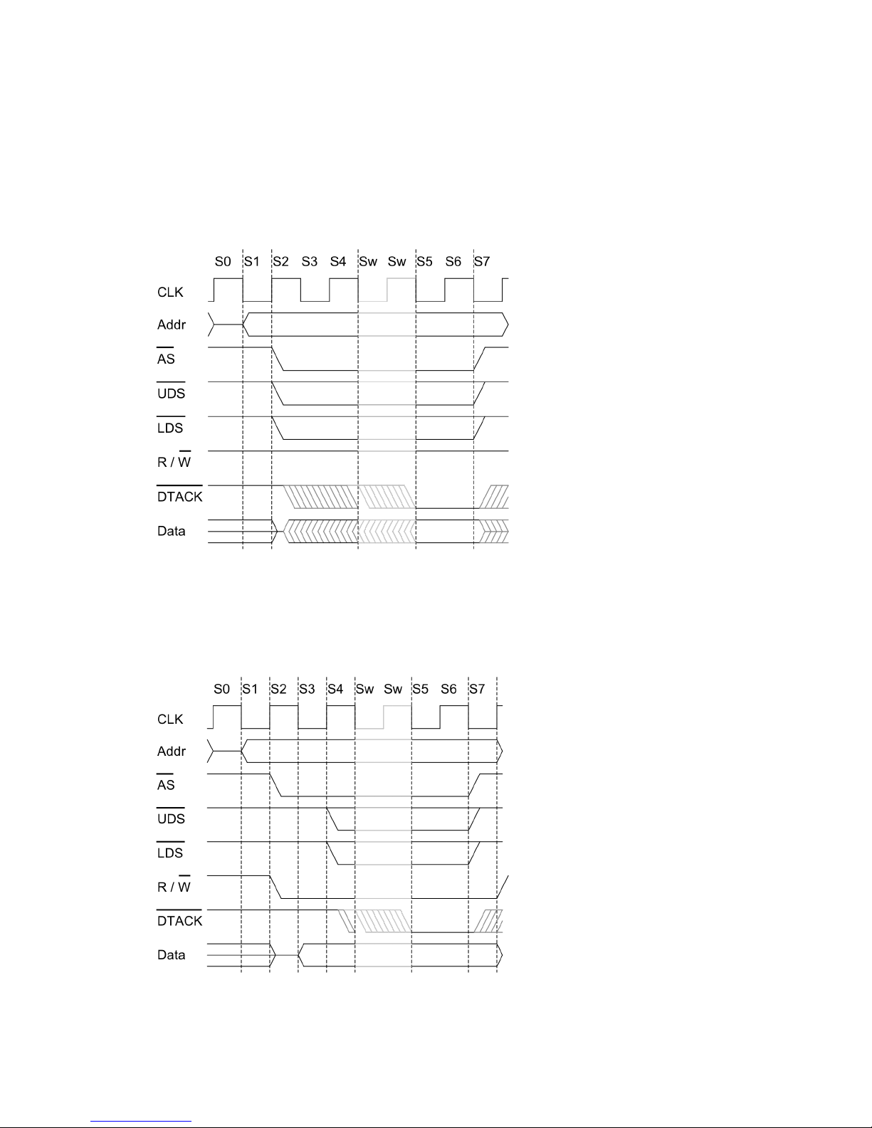
Delving deeper into bus cycle timing details, the processor state over the bus cycle
changes on each phase of the clock signal. In a Read cycle, as seen in Figure 8 below,
the address lines (A1-A23) are established at the falling edge starting state S1. The
remaining control signals (/AS, /UDS, /LDS & R/W ! ) are established at the rising edge
starting processor state S2. External bus circuitry may now complete the cycle. The
cycle termination signals are next checked by the processor at the falling edge at the end
of state S4. This provides a window of one and a half clock periods to complete the cycle
without requiring wait states. In a Write cycle, shown in Figure 9 below, A1-A23 are set
up at the start of S1, /AS and R/W ! are set up in S2, and then /UDS and /LDS are set up
on the rising edge starting state S4. As with the Read cycle, termination is next checked
at the falling edge closing state S4. This provides a window of only half of a clock
Page 21
68000 Motherboard User’s Manual Rev. A
Page 21 of 54
period without wait states. However, since the address, data and control lines are
maintained by the processor for a clock period after the cycle is terminated, the addressed
device has a one and a half clock period window to complete its write operation. For
reference, see the bus cycle timing diagrams in the Bus Operations sections of the
Motorola 68000 User’s Manual.
Figure 8: Regular Bus Read Cycle
Here the Address Bus,
/AS, /UDS, /LDS and
R/W ! signals are
generated by the
processor to control
bus. The Data Bus and
/DTACK signals, then,
are generated in
response by the
external hardware.
The Data Bus supplies
the data to be read into
the processor, and
/DTACK signals
completion of the
cycle.
Figure 9: Regular Bus Write Cycle
Here again the Address
Bus, /AS, /UDS, /LDS
and R/W ! signals are
generated by the
processor to control
the bus. However in
the Write Cycle, the
Data Bus is also driven
by the processor as it
asserts data to be
written to the target
device. The /DTACK
is generated in
response by the
external hardware to
signal completion of
the cycle.
Page 22

68000 Motherboard User’s Manual Rev. A
Page 22 of 54
6.4.2
Bus Termination int o a 6800 Bus Cycle
At the release of the 68000 into the marketplace, a rich set of peripheral devices was
already available for the established 6800 and other compatible processors. To leverage
this existing arsenal of peripherals, the 68000 provides a bus backward-compatibility
mode for interfacing with these elder devices. This mode is entered when the processor
receives a /VPA signal during the regular bus cycle in place of /DTACK. This drives the
processor into a 6800 bus cycle instead. The processor’s E clock, which runs at one-tenth
the frequency of the system clock, is then used to trigger the processor’s /VMA output.
And this output serves as an address enable signal for the 6800 bus logic to begin the
6800 bus cycle. This cycle closes automatically with the advance of the E clock.
7 Circ uit Description
The subsequent sections provide additional detail to the function and operation of the
MB68k-100 motherboard’s subcircuits. Refer to section 12 for references to additional
documentation.
7.1 Power Input
To start, the MB68k-100 motherboard requires DC input power. This may be provided
either through the barrel connector, A1J120, or the terminal block connector, A1TB120.
The barrel connector has a 2.1mm inner diameter and 5.5mm outer. It receives a barrel
plug, such as the CUI Inc., PP3-002AH. This is available through Digi-Key under
distributor part number CP3-002AH-ND. The positive connection is made through
center pin. Alternatively, for the A1TB120 terminal block connection, position 1 is
negative and position 2 is positive. It accepts 16-30 AWG wire.
Figure 10: Power Input Connectors
Page 23

68000 Motherboard User’s Manual Rev. A
Page 23 of 54
7.1.1
Voltage Regulat ion
Internally the electronics operates on +5VDC. This may be provided externally or
generated by the on-board voltage regulator. The current consumption of the MB68k100 motherboard is roughly 400mA, when operating at 10MHz. If the voltage regulator
is used, a minimum input voltage of +8VDC is recommended to allow for the voltage
drop of reversal protection and voltage regulator circuits. Limited by power dissipation
in the voltage regulator, the maximum input voltage recommended is around +12VDC,
where there is no additional load beyond the MB68k-100 board. If the voltage regulator
is bypassed with A1JP121, the input voltage must still compensate for the drop across the
reversal protection FET. This FET’s resistance at that voltage is approximately 300m!,
requiring an input voltage of about +5.12VDC minimum at 10MHz. The reversal
protection FET may also be bypassed with jumper A1JP120, if that function is not
desired.
7.1.2
Active Reversed Connecti on Protecti on
The power input section circuitry offers protection against reversed polarity. This circuit
employs a P-Channel FET switch in-line with the positive connection that conducts only
under proper polarity. Under reversed polarity this FET switch opens and prevents
current flow. With proper polarity, a side effect of the FET’s operation is that it
introduces a slight voltage drop on the positive supply line as a function of input voltage
and current. At +5VDC, the FET resistance is approximately 300m! of inline resistance.
A bypass jumper, A1JP120, allows the FET to be circumvented.
7.1.3
Discrete Voltage Supervisor
The Discrete Voltage Supervisor is designed to provide reset control of the processor. It
controls the processor’s reset signals for start-up, supply voltage brown-out and input
from the Reset Button, A1S140. The circuit is crafted for fast and monotonic assertion of
the Reset signals in response to any reset trigger. Both the 68000’s /HALT and /RESET
signals are provided as required for processor control. The circuit is enabled with
insertion of the A1JP140 /HALT and A1JP141 /RESET enable jumpers. When these
jumpers are installed, their corresponding pull-up resistors, R151 and R152, may be
populated in the board assembly, but they are not required since the /HALT and /RESET
signals already incorporate pull-ups.
On start-up, the circuit drives a reset period of approximately 1.5s. This is more than
sufficient to meet the 100ms power-up reset requirement of the 68000, described in
section on Reset Operation in the Motorola 68000 User’s Manual.
The Discrete Voltage Supervisor also monitors the system’s DC supply voltage for
voltage droop and power supply glitches. Under such an event, reset is issued to the
digital logic to avoid errant operation due to insufficient supply voltage. The low voltage
Page 24

68000 Motherboard User’s Manual Rev. A
Page 24 of 54
threshold for reset trigger is controlled by the R140x/R141x resistor divider network. The
threshold voltage per the base design is nominally 4.9V, with the tolerance range
bounded between 4.7V and 5.0V. This selection meets both the minimum typical power
voltage requirement for TTL logic at 4.5V, while permitting operation with a standard
+5.0VDC supply.
The Reset Button, A1S140, allows the user to physically initiate a reset. This button is
debounced in hardware.
The Alternate Supervisor Access header exposes the internal reset signaling that feeds the
buffers on each output. This offers the ability to allow for an alternate reset circuit to be
installed. The connector also makes DC power and the on-board circuit output available.
For further technical detail, refer to design document Discrete Voltage Supervisor Design
for Digital Logic, A.
7.2 The 68000 Microprocessor
Central to the motherboard design is the 68000 microprocessor. This processor sports a
16-bit data bus compatible with paired 8-bit devices. Its 24-bit address space supports
16MB of memory and memory-mapped I/O. The processor also offers a bus cycle
compatibility mode with 6800 peripheral devices, bus arbitration, prioritized interrupts,
execution state visibility through FCn outputs and run control. The PCB supports the
DIP-64 component package, which accommodates devices with clock speeds from 4 to
20MHz.
7.3 The ‘Pintercept ’ Headers
The processor is flanked by two 0.1" pitch, 2x32 pin headers. These are the ‘Pintercept’
headers, with reference designators INCPT100 and INCPT101. The intent is to provide
easy access to the processor pins for measurement or circuit modification. All 68000
signal lines arrive on one side of each of these headers, either to be passed across with
jumper connections or to be intercepted for modification. Corresponding connections are
made across the header by bridging between the first and second rows for each of the 32
pairs. The only exceptions to this are the power pins at INCPT100 positions 27, 28 and
31, 32 and at INCPT101 33, 34 and 40, 41. Although these pins are connected to the
respective power supply lines, the processor’s VCC and GND connections do not pass
through these jumpers. Generally, all other jumper connections should be made to assure
proper control of inputs and access to outputs.
7.4 Indicators
Four indicator lights are available to present the state of the system, as shown in Table 8.
They are enabled using the Indicator Enable, A1JP130.
Page 25

68000 Motherboard User’s Manual Rev. A
Page 25 of 54
Table 8: Indicators
Name
Color
Indication
Power
White
+5V system power present
Halt
Red
68000 /HALT signal is asserted
Reset
Yellow
68000 /RESET signal is asserted
Run
Green
68000 is actively addressing, signaling that
the microprocessor is running
7.5 The Syst em Cloc k
The system clock may be derived from one of several sources, as selected by the System
Clock Source Selector, A1JP112. See Table 11 below. An external clock signal may be
provided from the stack connector’s (CLKIN) pin, on position 16 of A1CON160/162.
Alternatively, on-board are both half-size (DIP-8, 4-pin) and full-size (DIP-14, 4-pin)
sockets for crystal oscillator modules. Also on-board is a discrete-component Pierce
crystal oscillator tested to operate up to 24MHz. The output of this oscillator is fed to a
divide-by-two divider for signal symmetry, providing a 12MHz output suitable for the
12MHz DIP-64 68000.
The Clock Frequency Divider circuit is also available to reduce the frequency. See
Figure 11 for an overview diagram. Its clock source may be selected as either of the
crystal oscillator modules or the discrete component oscillator. The Divider Source
Selector, A1JP111, selects the clock source for this divider. See Table 10 below. Its
divisor may be selected in the range of even numbers 2 through 18, as specified by the
Clock Divisor Selector, A1JP110. See Table 9 below.
The clock divider circuit includes the option to install an RC delay network in line with
its cycle reset signal. Although not found to be necessary, the delay may be used to
ensure that the D flip-flop output stage of IC111B is properly toggled before the divider
cycle of IC110 is reset. By default a simple jumper is installed in the delay path in place
of its resistor. The RC time constant, specified by R119 and C119, should be selected as
follows:
t
propag _ 7474
< t
delay
= R
R119
" C
C119
[ ]
<
1
2
T
CLK
# t
propag _ 4017
An inverted version of the system clock is available on the Stack Interface,
A1CON160/162 on position 20.
For technical details of the Discrete Crystal Clock design and Clock Frequency Divider,
refer to design documents 20.48MHz Pierce Crystal Oscillator, A and Clock Generator
Development, D.
Page 26

68000 Motherboard User’s Manual Rev. A
Page 26 of 54
Table 9: Clock Divisor Selector, A1JP110
Clock Divisor
Jumper Position
Note
2
1-2
This setting relies on the D flip-flop to clock during the
narrow response of the 4017 RESET. RESET timing may be
adjusted with the R119/C119 filter.
4
3-4
6
5-6
8
7-8
10
9-10
12
11-12
14
13-14
16
15-16
18
17-18
Table 10: Divider Source Selector,
A1JP111
Divider Source
Jumper
Position
OSCHCLK (OSC110)
1-2
OSCFCLK (OSC111)
3-4
Discrete Crystal
Oscillator
(XCLK_RAW)
5-6
Table 11: System Clock Source
Selector, A1JP112
Clock Source
Jumper
Position
OSCHCLK (OSC110)
1-2
OSCFCLK (OSC111)
3-4
Discrete Crystal
Oscillator
(XCLK_RAW)
5-6
Symmetric Discrete
Crystal Oscillator
(HXCLK_OUT)
7-8*
Symmetric Divided
Clock (CLKDIVOUT)
9-10
Stack Connector CLKIN
Input (CLKIN)
11-12
Page 27

68000 Motherboard User’s Manual Rev. A
Page 27 of 54
Figure 11: Clock Frequency Divider Overview
7.6 External R un Control
Inputs are provided within the stack connector interface to command the system’s /HALT
and /RESET signals. These are the HALT_CMD and RESET_CMD inputs, appearing at
A1CON160/162, pins 22 and 24 respectively. When left open, these inputs do not
interfere with the operation of these signals. However, asserting the inputs as logic high
commands the corresponding control signal to be asserted. These inputs provide a means
of externally controlling the Halt and Reset signal states of the system.
Following power-up, the 68000 processor must be held in reset with both /HALT and
/RESET lines asserted for a minimum of 100ms. This functionality may be provided by
the on-board Discrete Voltage Supervisor. For a subsequent reset after power-up, a pulse
of a minimum of 10 clock cycles must be applied to both /HALT and /RESET together to
accomplish the processor reset. For further detail, see reference number 56 in the ‘AC
Electrical Specifications’ section of the Motorola 68000 User’s Manual.
7.7 Reset Puls e Gener at or
The Reset Pulse Generator’s function is simple. It generates a pulse of at least one clock
cycle when the processor reset signal, /RESET, is released. It provides both positive and
negative polarity pulses on RST_PULSE and /RST_PULSE lines respectively, which are
made available on positions 25 and 26 of A1CON160/162. Only the /RST_PULSE
signal is used by the MB68k-100 circuitry. Internally, this reset pulse is used to latch onboard peripheral write registers to their initial, start-up values. These registers catch the
value of the LSB data bus, which has pull-down resistors that dominate during reset. The
on-board registers, therefore, start with a zero value.
Page 28
68000 Motherboard User’s Manual Rev. A
Page 28 of 54
Note the Reset Pulse Generator requires the /RESET signal be asserted for at least one
clock period. The Reset Pulse Generator only reflects release of the /RESET signal, not
/HALT. Processor execution of the RESET instruction drives only the /RESET line and
so triggers generation of a reset pulse.
Also note the erratum with the Reset Pulse Generator design when using the RESET
instruction, as described in section 11, item 5.
7.8 The Start Vector Selector (SVS)
On reset, the 68000 fetches its initial stack pointer and program counter values through
16-bit read cycles. The values read from addresses $000000 and $000002 constitute the
initial supervisor stack pointer address. Then values read from $000004 and $000006
constitute the program counter address from which code execution begins. Since the
processor follows the big-endian byte ordering scheme, most significant word for each
value occurs at the lowest address, and the least significant occurs at the highest address.
During these read cycles, the Function Code outputs of the processor also indicate
Supervisor Program space, with a code of 110 on the FCn lines.
The Start Vector Selector (SVS) allows easy control over assigning the start vector
address values. The values read for the initial stack pointer and program counter vectors
are specified according to the jumper configuration. Eight address bits corresponding to
address lines A16-A23 are specified on the Start Vector Address Selector jumper,
A1JP180. Other bytes read as zero. This jumper selectable range includes the Block
Address, making the memory device used for initialization code selectable. These bits
are address bits A20-A22, which correspond to A1JP180 bits 4-6 on positions 9-10, 1112 and 13-14. For example, a single jumper across pins 9-10, for position 5, presents the
starting address $100000. A typical configuration using on-board Bank 1 for
initialization utilizes a single jumper across position 2 for address $020000.
Table 12: SVS Assignment Map
Initial SSP
Initial PC
MSB
LSB
MSB
LSB
Address
00
01
02
03
04
05
06
07
Data
00
Jmpr
00
00
00
Jmpr
00
00
The SVS decoding logic does not include the state of the Function Code outputs, FCn. It
uses only the address lines to decode references to the start vector memory locations.
The SVS overrides any device otherwise referenced by these addresses. However, if the
Valid Peripheral Address (VPA) signal is asserted, the SVS function is suppressed. See
the section 7.11.2 for more on the VPA signal. The SVS also only operates as a 16-bit
device, regardless of the state of the Data Strobes. Since it is only active during a Read
Page 29

68000 Motherboard User’s Manual Rev. A
Page 29 of 54
Cycle when the Data Bus is not driven by the processor, this presents no conflict. The
SVS is enabled by the SVS Enable jumper, A1JP181.
Note that the SVS loads the 68000’s Supervisor Stack Pointer with the same address as
used for the Initial PC as the Reset vector. This memory location is probably not suitable
memory space for the stack. A first task for software is to initialize the SSP.
7.9 Address Space Mappi ng
The address space is decoded linearly by the on-board addressing logic, as shown in
Table 13.
The most significant bit of the address bus, A23, specifies peripheral address space for
‘legacy’ 6800 devices. The devices residing in this space are serviced with bus cycles
conforming to the 6800 bus architecture. On-board logic suppresses any other device
selection and asserts the /VPA signal, to launch the 6800 cycle.
The next three address lines, A22 - A20, specify the address block. The eight address
blocks each occupy 1MB of memory space, spanning addresses x00000 - xFFFFF. These
address blocks correspond to chip select lines /CS0 - /CS7.
Also, several on-board devices are included in the design. These may be mapped to a
Block Address as selected by the On-Board Block Address Selector, A1JP280. See the
section 7.12, On-Board Peripherals, for further detail.
It is customary to map the on-board devices to Block Address 0. It is also customary to
map SRAM to the start of this address block in support of a modifiable vector table for
the processor. The SVS maps to Block Address 0 by design and takes precedence over
devices overlaid at the same addresses, $000000 through $000007.
Table 13: Address Space Map
A23 - A20
A19 - A0
Name
Size
1xxx
$xxxxx
6800 Peripheral Space
8 MB
0111
$xxxxx
Address Block 7
1 MB
0110
$xxxxx
Address Block 6
1 MB
0101
$xxxxx
Address Block 5
1 MB
0100
$xxxxx
Address Block 4
1 MB
0011
$xxxxx
Address Block 3
1 MB
0010
$xxxxx
Address Block 2
1 MB
0001
$xxxxx
Address Block 1
1 MB
$FFFFF-
$00008
Address Block 0
1 MB
- 8 b
0000
$00000-
$00007
Start Vector Selector (SVS)
8 b
Page 30

68000 Motherboard User’s Manual Rev. A
Page 30 of 54
7.10
Data Strobed Flow L ogic
The 68000 microprocessor supports a 24-bit address bus but does this with only 23
address lines. Because its data bus width is 16-bit, two 8-bit devices may be serviced
simultaneously in a bus cycle. Since these two devices occupy separate, adjacent
addresses, the 68000 does not provide an A0 address line for the least significant bit in
the address. Instead, it provides two data strobes that signal access to each 8-bit device.
The Upper Data Strobe, /UDS, is associated with even addresses, where the A0 bit would
be zero. These addresses represent the byte of higher significance in a 16-bit operation
on data lines D8-D15. The Lower Data Strobe, /LDS, is associated with odd addresses,
where A0 would be one. And these addresses are the lower order byte within the 16-bit
operation on data lines D0-D7.
Using the Read/Write and Data Strobe signals from the microprocessor, the Data Strobed
Flow Logic generates distinct Read and Write enable signals for the Upper and Lower 8bit devices on the data bus. Labeled /RDU, /RDL, /WRU and /WRL, these signals may
be used to drive /OE and /WE inputs of bus devices directly.
7.11
Bus Cycl e Termination
At the introduction of the 68000, the market was dominated by processors that
anticipated the timely response of devices on the bus as part of the bus cycle. This meant
that the system as a whole was tightly coupled to the speed of the slowest bus device. To
avoid limitations on processor speed by slow bus devices, the 68000 instead uses what is
termed Asynchronous Bus Control. This bus control scheme uses acknowledge signals
for handshaking, in order to organize the progress of the bus transfer. And this allows
external logic to indicate when the bus cycle may proceed, without constraining the
processor clock speed to the slowest devices on the bus. These processor input signals
are the Bus Error (/BERR), the Valid Peripheral Address (/VPA) and the Data Transfer
Acknowledge (/DTACK). Each may be used to close a bus cycle, according to how the
processor is to proceed. The /BERR signal informs the processor that current bus request
is invalid, and the processor responds by invoking a Bus Error exception. The /VPA
signal informs the processor that the current bus cycle refers to an address space mapped
to devices requiring 6800 bus cycle compatibility. And the /DTACK signal informs the
processor that the current 68000 bus cycle is complete, and that it may advance to the
next operation. On-board circuitry is provided to generate all the signals.
The /DTACK Source Selector jumper, A1JP260, specifies the source for the
microprocessor’s /DTACK input.
Page 31

68000 Motherboard User’s Manual Rev. A
Page 31 of 54
7.11.1 Bus Termination wit h Auto /DTACK
Successful 68000 bus cycles are terminated by asserting the processor’s /DTACK input.
Circuitry is provided on-board to generate this signal. It responds by issuing a /DTACK
acknowledgment to an address occurring within one of the selected address blocks.
Address blocks are selected with the Automatic /DTACK Address Blocks Selector,
A1JP250. Multiple may be selected. This Auto /DTACK response is also generated for
a Start Vector Selector (SVS) reference or under a signal from the External /DTACK
signal, /DTACK_EXT.
7.11.2 Bus Termination wit h /VPA
The 68000 processor provides support for peripheral devices that use the ancestral 6800
processor interface. The 6800 bus cycle is initiated by the assertion of the /VPA signal
during the regular 68000 bus transaction. On-board circuitry is available to generate this
signal, using the A23 address line to designate the 6800 address space. This Peripheral
Address Decoder is enabled by installing the On-Board 6800 Peripheral Address Decode
Enable jumper, A1JP270. Addresses having the A23 bit set decode to the 6800 bus cycle
address space. The 6800 cycles are synchronous and terminate automatically on the E
clock, requiring no acknowledge signal to the processor to end the cycle.
The /VPA signal is also used during a 68000 Interrupt Acknowledge Cycle to request
Autovectoring. During the Interrupt Acknowledge Cycle, the processor requests the
interrupt vector number to indicate which interrupt service to execute for the pending
interrupt event. For this, the Interrupt Acknowledge Cycle is terminated by /DTACK.
However, termination of this bus cycle via /VPA commands the processor to use its
Autovectoring feature instead, where the interrupt vector number is directly assigned
according to the interrupt’s priority level. The /VPA generation for the 68000’s Interrupt
Acknowledge Cycle piggybacks on the Peripheral Address Decoder and also therefore
requires A1JP270 be enabled.
7.11.3 Bus Termination wit h /BERR
Bus cycles fail to terminate if no /DTACK or /VPA occurs, possibly the result of a
reference to an unmapped address. These cycles may be terminated through the Bus
Error Timer circuit. This circuit is a timer that begins counting down at the start of each
bus cycle, upon the assertion of /AS. The countdown is cancelled when the bus cycle
completes, upon the negation of /AS. If the timer completes its countdown while the bus
cycle is pending (/AS remaining asserted), then the /BERR signal is issued to the
processor. This represents failure of the bus cycle to terminate within the allotted period
and causes the processor to enter a Bus Error exception. The Bus Error Time Out
Selector, A1JP330, specifies the timeout period in clock cycles. The Bus Error Timer
Enable, A1JP331, enables the Bus Error Timer. For reference, see the section on Bus
Error Operation of the Motorola 68000 User’s Manual for further detail on the Bus Error
exception.
Page 32

68000 Motherboard User’s Manual Rev. A
Page 32 of 54
7.11.4 Wait State Generator
The design includes an on-board Wait State Generator. This may be installed by jumper
configuration. It appears in line with the Auto /DTACK signal, to provide support for
slower devices on the bus. The number of wait states to insert is selectable as either one
to five, or nine as specified by the Wait State Selector, A1JP260. This number of wait
states is imposed on every bus cycle terminated via the Auto /DTACK, regardless of the
address.
Wait states are required when the time taken for an addressed device to complete its bus
operation is greater than the period provided by the processor before /DTACK is tested to
close the bus cycle. This period is one and a half processor clock periods for both read
and write cycles. Each wait state provides one clock period of delay in the bus cycle.
For further detail on the bus cycle, see Bus Control Signal Timing in section 6.4.
7.12
On-Board P eripher als
Several on-board peripherals are included in the MB68k-100 design. The address space
for these peripherals, denoted as ONBD_BASE, may be selected via the On-Board Block
Address Selector, A1JP280. It may be mapped to any of the eight address blocks but is
typically located within Block Address 0. The on-board registers are summarized in
Table 14.
All on-board registers are initialized to zero upon reset. The reset occurs at the rising
edge of the M68K_RESET !!!!! line.
Page 33

68000 Motherboard User’s Manual Rev. A
Page 33 of 54
Table 14: On-Board Register Summary
Peripheral Name
ONBD_BASE
+offset
Size in bytes
Bits within
byte
Reset State
Quick Description
Interrupt Enable Register,
A1CON340
+$A0000
1
0-7
$00
Interrupt Logic control
Clock Synchronization
Register
+$C0000
1
Input signals
synchronized to clock
On-Board Interrupt Logic Level
0-2
$07
On-Board Interrupt
Logic Level
Hardware Entropy Generator
3 XX
Hardware Entropy
Generator Bit
On-Board Digital Input Interface,
A1CON300
4-7
XX
On-Board Digital Input
Interface
On-Board Output Latch,
A1CON290
+$E0000
1
0-7
$00
Discrete digital output
signal latch
7.12.1 Int errupt En able Register
Ref. Des.: A1CON340
Addr: ONBD_BASE+$A0000 (Interrupt Enable Register)
Name: ONBD_INTEN
Size: 8 bit
Reset: $00
The Interrupt Enable Register is an 8-bit register that controls the availability of the OnBoard Interrupt Logic to trigger interrupts. Bit 0 of this register is a global mask, set to 1
to disable all 7 levels of interrupt sources. Bits 1-7 are individual controls for each of the
7 interrupt levels, organized respectively. With its bit set to 1, the corresponding
interrupt level is available for trigger. When an interrupt occurs, this bit must be cleared
by software to reset the interrupt logic for that interrupt level. It may then be restored to
1 to resume triggering at that interrupt level. For deeper detail, see section 7.13, Interrupt
Logic, below.
7.12.2 The Clock Synchronization Register
Addr: ONBD_BASE+$C0000 (Clock Synchronization Register)
Name: ONBD_SYNC
Size: 8 bit
External events to the system clock are synchronized through the Clock Synchronization
Register. However, this register does not synchronize asynchronous transitions of
Page 34

68000 Motherboard User’s Manual Rev. A
Page 34 of 54
parallel groups of bits. If an external asynchronous transition straddles a positive clock
edge, spurious data may result.
Writes to this register are ignored, but the write operation is signaled on the
TP_WRDECRST_6 test point.
Table 15: Clock Synchronization Register Breakdown
Bits
Description
0-2
On-Board Interrupt Logic Level
3
Hardware Entropy Generator Bit
4-7
On-Board Digital Input Interface
7.12. 2.1 On-Board Interru pt Logic Le vel
Addr: ONBD_BASE+$C0000 (Clock Synchronization Register), bits 0-2
Size: 3 bit
Bits 0-2 of the Clock Synchronization Register report the current interrupt level
recognized by the Interrupt Logic. These three bits represent the output of the on-board
Interrupt Logic that may be connected to the processor’s /IPLn pins through the OnBoard Interrupt Logic Enable, A1JP310. It indicates the highest priority level interrupt
event pending. See the Interrupt Logic section for further detail.
7.12. 2.2 The Hardware Ent ropy Genera tor
Addr: ONBD_BASE+$C0000 (Clock Synchronization Register), bit 3
Size: 1 bit
The Hardware Entropy Generator circuit provides a bit whose state is the result of
measuring an avalanche process of a reverse biased diode. This bit appears as bit 3 of the
Clock Synchronization Register. The intent is that the avalanche process has an
unpredictable behavior over time and that this can be used as a rudimentary source of
random data for the software application. The avalanche events are accumulated in
hardware by a flip-flop, in order to take advantage of the tally of avalanche events that
occur between software samplings, rather than the instantaneous diode state. This was
done to reduce duty cycle bias of the diode’s conducting condition.
With no rigorous development, the typical entropy bandwidth available from the circuit is
estimated as 20k bits/sec in bench testing. Actual performance many vary over a wide
range of factors. But the logic behind this estimate is based on two contributing factors.
The first is the empirically measured average time between bit state transition cycles,
under the interpretation that the state is suitably randomized after this period has elapsed.
Page 35

68000 Motherboard User’s Manual Rev. A
Page 35 of 54
The second is the empirically measured duty cycle of the tallied output. According to
Shannon’s definition of information, a bias in this state resulting in an uneven duty cycle
reduces the entropy contribution of the bit by the following.
S = " pnlog p
n
( )
n=1
#
$
% " D & log2D
( )
+ 1 " D
( )
& log21" D
( )
[ ]
where S is the entropy contribution per sample expressed in bits,
and D is the duty cycle of the digital waveform.
It is worth noting that high lighting conditions may adversely affect the operation of this
entropy generator. Since the circuit relies on sporadic breakdown of a reverse biased
semiconductor junction, increased concentrations of electron-hole pairs spawned by
brightly lit conditions on the clear body of the germanium diode may reduce the
occurrence of these triggerable breakdown events.
Measurements for the estimate provided above are taken at 20°C ambient under typical
indoor lighting conditions and were roughly consistent across various circuit components
in bench test. The selection of any particular avalanche diode was the key driver
impacting the entropy generator’s performance. Of course, generating randomness is a
cryptic art, and in no way should this entropy source be considered ‘cryptologically
secure’ or even critically reliable.
Example output of the Hardware Entropy Generator is given below in Table 17 per the
high-speed sampling program snippet given in Table 16. The program was executed on
MB68k-100 hardware at 10.24MHz microprocessor clock speed, in ambient lighting and
at approximately 22°C. Differences observed primarily follow the selection of the
particular avalanche diode component. The results varied widely as different 1N34A
diodes were tested with all other components unchanged. Changes to other components
resulted in little impact.
Table 16: Entropy Sampler
MOVEA.L #$400, A0
Set up the target address of the buffer into which to
write the samples.
MOVE.L #$FB00, D7
Specify the number of samples to take.
RANDSAMPLOOP:
Establish the loop start point.
MOVE.B
ONBD_SYNC, (A0)+
Capture a sample from the Hardware Entropy
Generator.
DBF D7, RANDSAMPLOOP
Iterate through the loop until the specified number
of samples has been taken.
Page 36

68000 Motherboard User’s Manual Rev. A
Page 36 of 54
Table 17: Sample Output of the Hardware Entropy Generator
MB68k-100A, S/N 001
10101010101010101011010101011010101101010111010101101010101010110101010101010101
01010101010101010101010101010101010101010101010101011010101101010110101010101010
10101010101010101010101101101011101010101011010101010101010101010101010101101010
10101010101010110101010101101010110101101010101101011011010110110110101101101101
01010101110101010101010110110101110101010110101011010101010101011101101010101010
11010101101010110101010101101010101101010101011011010101010110101010101010101010
10110111010101010101101101010101010101010101010101010101010101101101011010101101
01010101010101010110110101010101010110101010101010101010101010101010101010111011
01010101010110101101010101010101010110101101011010101101110101010101010101010110
11010101010111010101101011010101010110101010101101011010101011010101010101101011
01101010101011011010110101010101010101010110101010101010101110101010101110101011
01010101101010101011010101011010101010110101101010110101101010101010101101110101
11010010101010101010101010101010101010101011101010101010101101010101010110110101
01101010110101011010101010101110101101101011010101010101010101010110101010101010
10101010101010101011010101010101010101010101010101101010101011010110101010101010
10111010101010101010110101101010101010101010101010111010101010101011010101010101
MB68k-100A, S/N 002
11100001111110000111111000011111100000000000000000001111111111000011111100001111
11000011111111111111111111111110000000000111100000011110000001111000000000000000
00000000001111111111000011111100001111110000000000111111111111111111111111111111
11100000011110000001111000000111111111111111111111111111110000111111000011111100
00111111111111111111111111111111111111111000000111100000011111111111111111111111
11111111111111110000111111000011111100000000001111111111000000000111111111100001
11111111100000011111111110000000000111111111000000000011110000001111000000111100
00001111111111111111111111111111100001111110000111111000011111100001111110000000
00000000000011110000001111000000111100000011111111111111111111111111111000011111
10000111111000011111100001111111111111111111111111000000000011111111110000111111
00001111110000000000000000000111111111100001111110000111111111111111111111111111
11111111111111111100001111110000111111000000000011101111111111111110000000000111
10000001111000000111111111100000000000000000001111111111000011111100001111110000
00000011110000001111111111111111111000011111100001111110000111111000000000011111
11110000000000111100000011110000001111000000111100000000000000000000000001111000
00011110000001111000000111100000000000000000000000001111000000111100000011110000
7.12. 2.3 On-Board Digital Input Interface
Ref. Des.: A1CON300
Addr: ONBD_BASE+$C0000 (Clock Synchronization Register), bits 4-7
Size: 4 bit
Open State: 0
The On-Board Digital Input Interface provides four bits of digital input though
A1CON300. Pins 1 through 4 are system negative. The odd pins above that, pins 5, 7, 9
and 11, are system positive. The even pins, 6, 8, 10 and 12, correspond to bits 4-7 of the
Page 37

68000 Motherboard User’s Manual Rev. A
Page 37 of 54
Clock Synchronization Register respectively. These pins each have a 10k! pull-down
resistance and 0.1µF capacitance to negative.
Again it should be noted that multi-bit data changes among parallel groups of bits may
result in spurious data being latched, if the change event straddles a positive clock edge.
This occurs if some, but not all, of the parallel bits are established to their new states at
the time of the clock transition.
7.12.3 On-Board O utput L atch
Ref. Des.: A1CON290
Addr: ONBD_BASE+$E0000 (On-Board Output Latch)
Name: ONBD_OUT1
Size: 8 bit
Reset: $00
The On-Board Output Latch provides eight discrete digital output signals, accessible via
the On-Board Digital Output Interface connector, A1CON290. These pins are driven
internally by a 74xx374 latch, which can typically source or sink a total of 25mA per pin.
The state of these bits also appears on the lower eight positions of the Digital Output
Light Bar, where an illuminated position indicates a logic high state. This light bar is
enabled via A1JP290. These lights are driven from the same 74xx374 latch as the output
pins and must be considered when accounting for total current. The latch initializes to
zero at start-up.
7.13
Int errupt Logic
On-board interrupt enable and latching logic is provided in hardware for use with the
68000’s Autovectoring functionality. This logic operates with an independent channel
for each of the seven interrupt levels. Each channel has an enable bit in the Interrupt
Enable Register. These bits are 1-7 for interrupt levels 1-7. Bit 0 of the register provides
a global mask to prevent new interrupt events from being triggered across all channels,
though all existing triggered events are retained. No new events will be triggered until
the global mask bit is returned to zero state. The initial state of the mask is zero at startup, enabling interrupts globally but disabling each channel individually.
Interrupt events are triggered by the latching hardware when the global mask is not
asserted and their corresponding enable bits are set high in the Interrupt Enable Register
at address ONBD_BASE+$A0000. While enable bits are zero, new interrupt events on
that level are ignored. However, any events already triggered remain in effect. The event
trigger is a low to high transition (positive edged) on the corresponding interrupt level’s
input. These inputs have integral 10k! pull-down resistors and may be left floating
when not used. The inputs are accessed through the Interrupt Source Interface connector,
Page 38

68000 Motherboard User’s Manual Rev. A
Page 38 of 54
A1JP340. The maximum hardware latency to the processor is the propagation delay of a
74xx74 and 74xx148 (13+19 ns typ., 25+30 ns max. at 25°C), plus one clock cycle.
The interrupt event latch may be cleared in software by disabling the corresponding
enable bit. The bit may subsequently be re-enabled to capture the next trigger event.
This sequence is used to acknowledge and reset from an interrupt event.
The on-board interrupt logic may be disabled from generating microprocessor interrupts
with the On-Board Interrupt Logic Enable jumper, A1JP310. This jumper is comprised
of three separate jumper connections for each of the individual /IPLn lines. The state of
the interrupt logic is available, regardless, on bits 0-2 of the Clock Synchronization
Register. Also, the /VPA generation for this function piggybacks on the Peripheral
Address Decoder and therefore requires A1JP270 be enabled.
7.14
On-Board M em ory Banks 0/1
On-Board Banks support EPROM/SRAM devices according to jumper settings, per the
configuration outlined in Table 18 below. EPROM device support ranges from 2732
(4kB x 2 devices) through to 27512 (64kB x 2 devices). Note that the 2732 device is
shifted in the socket with the device’s pin 1 positioned in pin 3 of the socket. With all but
the 27512, address wrap-around aliasing occurs due to ignored address lines.
Both 0.3" and 0.6" DIP-24/28 devices are compatible with each Bank, depending on the
socket installed. The MSB devices, which reside at the lower memory addresses, occupy
IC351 for Bank 0 and IC361 for Bank 1. The LSB devices, at higher addresses, occupy
IC350/360. Bank 0 maps to the On-Board Block Address, ONBD_BASE, with an offset
of +$00000. Bank 1 maps with an offset of +$20000.
Table 18: On-Board Memory Banks’ Configuration
Jumper
6264
62256
2732
2764
27128
27256
27512
JP350, JP360
A16/VPP
open
3-4
(Pos 2)
open
1-2
(Pos 1)
1-2
(Pos 1)
1-2
(Pos 1)
5-6
(Pos 3)
JP351, JP361
A14/CS
1-2
2-3
1-2
open
2-3
2-3
2-3
JP352, JP362
A15/PGM !!! /WRL !!!
3-4
(Pos 2)
3-4
(Pos 2)
open
1-2
(Pos 1)
1-2
(Pos 1)
5-6
(Pos 3)
5-6
(Pos 3)
JP353, JP363
A15/PGM !!!
/WRU !!!
3-4
(Pos 2)
3-4
(Pos 2)
open
1-2
(Pos 1)
1-2
(Pos 1)
5-6
(Pos 3)
5-6
(Pos 3)
Page 39

68000 Motherboard User’s Manual Rev. A
Page 39 of 54
7.15
Stack Interface
Functionality of the MB68k-100 motherboard may be expanded through its Stack
Interface. This interface is designed to support additional circuitry by providing access to
the internal buses and control signaling.
7.15.1 Stack Interface Con nectors
The MB68k-100 offers two 0.1" pitch headers, each with 2x32 pins, that may be used to
interface with a stack of mezzanine daughter boards. The connectors have reference
designators CON160 and CON161. The connectors are positioned on opposite sides of
the motherboard, parallel along their long dimensions. Two additional headers are
provided, CON162 and CON163. These are electrically pin-for-pin identical to the
former pair, respectively, and offer an additional opportunity for access. See Figure 12
on page 42 for a visual reference. See Table 19 and Table 20 for connector pin mapping.
The outermost pins on each side of each connector are connections to negative, ensuring
that the negative contact is made first in case of a hot insertion. This practice, however,
is not intended.
Table 19: Stack Connector CON160/CON162 Pin Map
Name
Description
Pin
Pin
Name
Description
GND
Supply Negative
1 2 GND
Supply Negative
VCC
Supply Positive
3 4 VCC
Supply Positive
M68K_AS !!
68000 Address
Strobe
5 6 M68K_UDS !!!
68000 Upper Data
Strobe
M68K_LDS !!!
68000 Lower
Data Strobe
7 8 M68K_R/W !
68000 Read/Write
W/R !
Inverted 68000
Read/Write
9
10
M68K_DTACK !!!!!!
68000 Data Transfer
Acknowledge
DTACK_EXT !!!!!!!!!
External
/DTACK input
11
12
AUTO_DTACK !!!!!!
On-Board Automatic
/DTACK output
M68K_BG !!
68000 Bus Grant
13
14
M68K_BGACK !!!!!!
68000 Bus Grant
Acknowledge
M68K_BR !!
68000 Bus
Request
15
16
CLKIN
Clock input
HXCLK_OUT
Symmetric
Discrete Clock
(Frequency/2)
17
18
CLKDIVOUT
Symmetric Clock
Frequency Divider
Output
CLK
System Clock
19
20
CLK !!!
Inverted System
Clock
M68K_HALT !!!!
68000 Halt
21
22
HALT_CMD
Input to Command
68000 Halt
M68K_RESET !!!!!
68000 Reset
23
24
RESET_CMD
Input to Command
68000 Reset
RST_PULSE
Minimum One
Clock Cycle
Pulse on 68000
Reset Transition
from 0 to 1
25
26
RST_PULSE !!!!!!!!!
Inverted
RST_PULSE
Page 40

68000 Motherboard User’s Manual Rev. A
Page 40 of 54
M68K_VMA !!!
68000 Valid
Memory Address
27
28
M68K_E
68000 Enable (E)
Clock
M68K_VPA !!!
68000 Valid
Peripheral
Address
29
30
M68K_BERR !!!!
68000 Bus Error
M68K_ IPL2 !!!!
68000 Interrupt
Priority Level, bit
2
31
32
M68K_ IPL1 !!!!
68000 Interrupt
Priority Level, bit 1
M68K_ IPL0 !!!!
68000 Interrupt
Priority Level, bit
0
33
34
M68K_FC2
68000 Function
Code Output, bit 2
M68K_FC1
68000 Function
Code Output, bit
1
35
36
M68K_FC0
68000 Function
Code Output, bit 0
RDL !!!
Read Enable,
lower byte
37
38
RDU !!!
Read Enable, upper
byte
WRL !!!
Write Enable,
lower byte
39
40
WRU !!!
Write Enable, upper
byte
CS0 !!!
Block Address 0
Select
41
42
CS1 !!!
Block Address 1
Select
CS2 !!!
Block Address 2
Select
43
44
CS3 !!!
Block Address 3
Select
CS4 !!!
Block Address 4
Select
45
46
CS5 !!!
Block Address 5
Select
CS6 !!!
Block Address 6
Select
47
48
CS7 !!!
Block Address 7
Select
ADDR_DEC_EN
Input to actively
disable the OnBoard Block
Address Decoder
49
50
STACKEVEN50
Unused
STACKEVEN51
Unused
51
52
STACKEVEN52
Unused
STACKEVEN53
Unused
53
54
STACKEVEN54
Unused
STACKEVEN55
Unused
55
56
STACKEVEN56
Unused
STACKEVEN57
Unused
57
58
STACKEVEN58
Unused
STACKEVEN59
Unused
59
60
STACKEVEN60
Unused
VCC
Supply Positive
61
62
VCC
Supply Positive
GND
Supply Negative
63
64
GND
Supply Negative
Table 20: Stack Connector CON161/CON163 Pin Map
Name
Description
Pin
Pin
Name
Description
GND
Supply Negative
1 2 GND
Supply Negative
VCC
Supply Positive
3 4 VCC
Supply Positive
STACKODD5
Unused
5 6 M68K_A1
68000 A1
M68K_A2
68000 A2
7 8 M68K_A3
68000 A3
M68K_A4
68000 A4
9
10
M68K_A5
68000 A5
M68K_A6
68000 A6
11
12
M68K_A7
68000 A7
M68K_A8
68000 A8
13
14
M68K_A9
68000 A9
M68K_A10
68000 A10
15
16
M68K_A11
68000 A11
Page 41

68000 Motherboard User’s Manual Rev. A
Page 41 of 54
M68K_A12
68000 A12
17
18
M68K_A13
68000 A13
M68K_A14
68000 A14
19
20
M68K_A15
68000 A15
M68K_A16
68000 A16
21
22
M68K_A17
68000 A17
M68K_A18
68000 A18
23
24
M68K_A19
68000 A19
M68K_A20
68000 A20
25
26
M68K_A21
68000 A21
M68K_A22
68000 A22
27
28
M68K_A23
68000 A23
M68K_D0
68000 D0
29
30
M68K_D1
68000 D1
M68K_D2
68000 D2
31
32
M68K_D3
68000 D3
M68K_D4
68000 D4
33
34
M68K_D5
68000 D5
M68K_D6
68000 D6
35
36
M68K_D7
68000 D7
M68K_D8
68000 D8
37
38
M68K_D9
68000 D9
M68K_D10
68000 D10
39
40
M68K_D11
68000 D11
M68K_D12
68000 D12
41
42
M68K_D13
68000 D13
M68K_D14
68000 D14
43
44
M68K_D15
68000 D15
STACKODD45
Unused with test
point
45
46
STACKODD46
Unused with test
point
STACKODD47
Unused with test
point
47
48
STACKODD48
Unused with test
point
STACKODD49
Unused with test
point
49
50
STACKODD50
Unused with test
point
STACKODD51
Unused with test
point
51
52
STACKODD52
Unused with test
point
STACKODD53
Unused
53
54
STACKODD54
Unused
STACKODD55
Unused
55
56
STACKODD56
Unused
STACKODD57
Unused
57
58
STACKODD58
Unused
STACKODD59
Unused
59
60
STACKODD60
Unused
VCC
Supply Positive
61
62
VCC
Supply Positive
GND
Supply Negative
63
64
GND
Supply Negative
7.15.2 Mounting Holes
The motherboard also offers ten mounting holes for securing the MB68k-100
motherboard, as well as any mezzanine boards installed. These mounting holes have an
inner diameter of 0.126" (3.2mm). Their positions are shown in Figure 12. Suitable
mounting hardware is listed in Table 21 below.
Page 42

68000 Motherboard User’s Manual Rev. A
Page 42 of 54
Figure 12: Mounting Hole Positions
Table 21: Mounting Hardware Options
Item Type
Item Detail
Manufacturer
Manu. P/N
Distributor
Dist. P/N
Standoff,
PC/104
4/40, .600",
M/F, Hex,
Nylon
Keystone
Electronics
4799
Digi-Key
4799K-ND
Standoff,
PC/104
4/40, .600",
M/F, Hex,
Brass
Keystone
Electronics
8799
Digi-Key
8799K-ND
Hardware,
Nut
4-40,
0.062"
thick,
0.184"
width,
Brass
Tyco
Electronics
5205821-2
Digi-Key
A35230-ND
Page 43

68000 Motherboard User’s Manual Rev. A
Page 43 of 54
7.16
Quick Jumper Reference
The asterisk denotes default jumper position.
Jumper Ref.
Des.
Jumper Name
Description
Position
Jumper Position Description
A1JP110
Clock Divisor
Selector
Selects Clock Frequency Divider rate
Pos 1
Divide by 2
Pos 2
Divide by 4
Pos 3
Divide by 6
Pos 4
Divide by 8
Pos 5
Divide by 10
Pos 6
Divide by 12
Pos 7
Divide by 14
Pos 8
Divide by 16
Pos 9
Divide by 18
A1JP111
Divider Source
Selector
Selects the clock signal source for the Clock
Frequency Divider
Pos 1
Half-size clock module OSC110 (OSCHCLK)
Pos 2
Full-size clock module OSC111 (OSCFCLK)
Pos 3
Raw output from Discrete Crystal Clock (XCLK_RAW)
A1JP112
System Clock Source
Selector
Selects the system clock source
Pos 1
Half-size clock module OSC110 (OSCHCLK)
Pos 2
Full-size clock module OSC111 (OSCFCLK)
Pos 3
Raw output from Discrete Crystal Clock (XCLK_RAW)
Pos 4*
Symmetric Discrete Crystal Oscillator (HXCLK_OUT)
Pos 5
Symmetric Divided Clock (CLKDIVOUT)
Pos 6
Stack Connector CLKIN Input (CLKIN)
A1JP120
Reversal Prot Bypass
Provides bypass of the Active Reversed
Connection Protection
1-2
Bypass
A1JP121
Voltage Regulator
Bypass
Provides bypass of the Voltage Regulation
1-2
Bypass
A1JP130
Indicator Enable
Enables indicator lights
1-2*
Enable
A1JP140
Supervisor /HALT
Enable
Enables Discrete Voltage Supervisor to control
M68k’s /HALT
1-2*
Enable
A1JP141
Supervisor /RESET
Enable
Enables Discrete Voltage Supervisor to control
M68k’s /RESET
1-2*
Enable
Page 44

68000 Motherboard User’s Manual Rev. A
Page 44 of 54
A1JP180
Start Vector Address
Selector
Presents byte value for reads of addresses 1 and
5 for specifying initial start address for
execution and supervisor stack pointer
Pos 1
Initial SSP/PC bit 16
Pos 2*
(0x00020000
for on-board
Bank 1)
Initial SSP/PC bit 17
Pos 3
Initial SSP/PC bit 18
Pos 4
Initial SSP/PC bit 19
Pos 5
Initial SSP/PC bit 20
Pos 6
Initial SSP/PC bit 21
Pos 7
Initial SSP/PC bit 22
Pos 8
Initial SSP/PC bit 23
A1JP181
SVS Enable
Enables the Start Vector Selector
1-2*
Enable
A1JP250
Automatic /DTACK
Address Blocks
Selector
Includes automatic bus cycle acknowledgement
for specified Block Addresses
Pos 1*
Include Block Address 0, /CS0
Pos 2
Include Block Address 1, /CS1
Pos 3
Include Block Address 2, /CS2
Pos 4
Include Block Address 3, /CS3
Pos 5
Include Block Address 4, /CS4
Pos 6
Include Block Address 5, /CS5
Pos 7
Include Block Address 6, /CS6
Pos 8
Include Block Address 7, /CS7
A1JP260
/DTACK Source
Selector
Selects M68k /DTACK control source
Pos 1*
Automatic acknowledgement from Automatic /DTACK Feedback
Pos 2
External /DTACK from Stack Connector
Pos 3
Automatic acknowledgement with 1 Wait State
Pos 4
Automatic acknowledgement with 2 Wait State
Pos 5
Automatic acknowledgement with 3 Wait State
Pos 6
Automatic acknowledgement with 4 Wait State
Pos 7
Automatic acknowledgement with 5 Wait State
Pos 8
Automatic acknowledgement with 9 Wait State
A1JP270
On-Board 6800
Peripheral Address
Decode Enable
Enables M68k /VPA control by the A23
address line
1-2*
Enable
A1JP280
On-Board Block
Address Selector
Selects Block Address for on-board peripheral
devices and memory banks
Pos 1*
Block Address 0, /CS0
Pos 2
Block Address 1, /CS1
Page 45
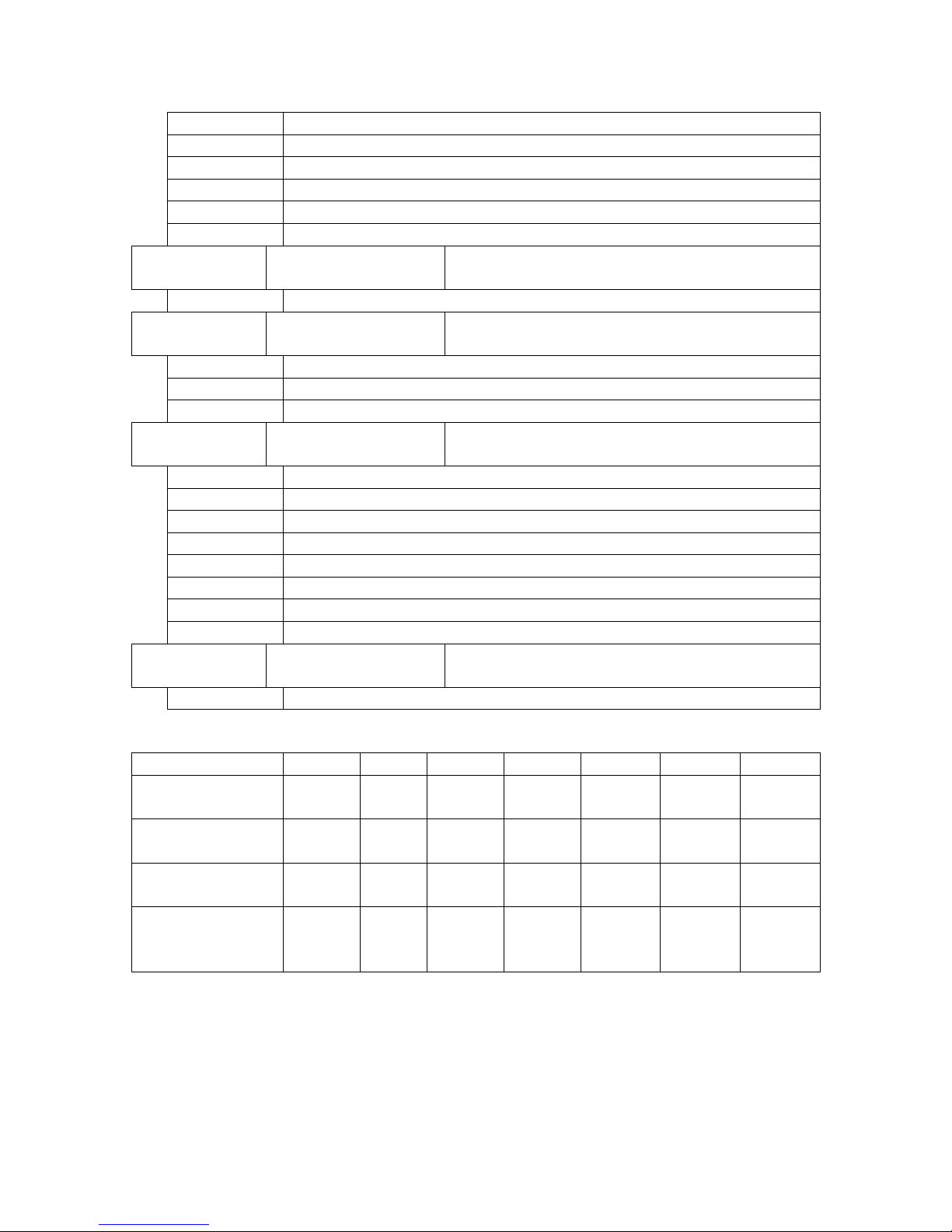
68000 Motherboard User’s Manual Rev. A
Page 45 of 54
Pos 3
Block Address 2, /CS2
Pos 4
Block Address 3, /CS3
Pos 5
Block Address 4, /CS4
Pos 6
Block Address 5, /CS5
Pos 7
Block Address 6, /CS6
Pos 8
Block Address 7, /CS7
A1JP290
Digital Output Light
Bar Enable
Enables light bar to display output latch state
1-2*
Enable
A1JP310
On-Board Interrupt
Logic Enable
Enables/selects control from on-board logic
control for interrupts
Pos 1*
Connects /IPL0
Pos 2*
Connects /IPL1
Pos 3*
Connects /IPL2
A1JP330
Bus Error Time Out
Selector
Select the number of clock cycles until Bus
Error timeout
Pos 1
Timeout of 32 clock cycles
Pos 2
Timeout of 64 clock cycles
Pos 3*
Timeout of 128 clock cycles
Pos 4
Timeout of 256 clock cycles
Pos 5
Timeout of 512 clock cycles
Pos 6
Timeout of 1024 clock cycles
Pos 7
Timeout of 2048 clock cycles
Pos 8
Timeout of 4096 clock cycles
A1JP331
Bus Error Timer
Enable
Enables Bus Error Timer
1-2*
Enable
Jumper
6264
62256
2732
2764
27128
27256
27512
JP350, JP360
A16/VPP
open
3-4
(Pos 2)
open
1-2
(Pos 1)
1-2
(Pos 1)
1-2
(Pos 1)
5-6
(Pos 3)
JP351, JP361
A14/CS
1-2
2-3
1-2
open
2-3
2-3
2-3
JP352, JP362
A15/PGM !!! /WRL !!!
3-4
(Pos 2)
3-4
(Pos 2)
open
1-2
(Pos 1)
1-2
(Pos 1)
5-6
(Pos 3)
5-6
(Pos 3)
JP353, JP363
A15/PGM !!!
/WRU !!!
3-4
(Pos 2)
3-4
(Pos 2)
open
1-2
(Pos 1)
1-2
(Pos 1)
5-6
(Pos 3)
5-6
(Pos 3)
Page 46

68000 Motherboard User’s Manual Rev. A
Page 46 of 54
Circuit
Reference Designator
Default Status
R115
Not Installed
Clock Trace AC Terminator
C115
Not Installed
Clock Series Termination
R116
Jumper Installed
R119
Jumper Installed
Clock Frequency Divider
reset delay
C119
Not Installed
8 The Softer Side
The design of a computer system is a two stage process: hardware and software. On to
the latter…
8.1 Softw are D evelopment Tools
Being based on the 68000 processor, a wide range of tools is freely available for software
development of the MB68k-100. Among them are the following.
8.1.1
m68k-elf
m68k-elf is a development suite for command line software development under Linux,
Cygwin and other environments. Its assembly language support uses AT&T mnemonics.
Table 22: Basic m68k-elf Assembler Script
With the script named m, the project files are all assumed
to have the file name projName with their appropriate
extension by file type.
> m projName
m68k-elf-as -m68000
-o $1.o $1.s
Assemble source code specified in the command line
to create object file
m68k-elf-objcopy
--input-target=binary
--output-target=srec
$1.o $1.srec
Translate object to Motorola S-Record
m68k-elf-objdump
-m68000 -D $1.srec
> $1.disassembly
Generate disassembly of created object for review
m68k-elf-objcopy
-O binary $1.o $1.bin
Translate object to raw binary
m68k-elf-objcopy
-O binary -b 0 -i 2
$1.o $1.bin.even
Generate 'even' file from binary with MSB's
m68k-elf-objcopy
-O binary -b 1 -i 2
$1.o $1.bin.odd
Generate 'odd' file from binary with LSB's
Page 47

68000 Motherboard User’s Manual Rev. A
Page 47 of 54
8.1.2
EASy68K
This educational development tool by Chuck Kelly is an excellent environment for
development and simulation of 68000 assembly code. It requires a Windows platform
computer. Its tools allow for the generation of Motorola S-Record output files. These
files may then be used to generate split binary files for the even and odd program
memory ROMs. Even ROMs store the upper bytes and have the suffix “_0.” These are
referred to as “Hi.” Odd ROMs store the lower bytes and have the suffix “_1.” These are
“Lo.” Visit www.easy68k.com.
8.2 MB68k-100 Softwar e Examples
The following pair of programming examples demonstrates the same function: to fill a
continuous block of memory with a specified byte value. The first is implemented with a
simple structure for ease of readability. The second is implemented to complement the
68000’s architecture for optimum speed.
********************************************************************************
* BlockFillB (trival version)
* Implements memory fill function with a byte value
*
* Input:
* D0.L - Block length to fill
* D1.B - Byte fill value
* A0.L - Target block base address
*
* Output:
* None
*
* Registers Destroyed:
* A0, D0.L, D1.L
*
********************************************************************************
BLOCKFILLB:
Label to indicate the start of the BLOCKFILLB routine.
; return if fill length is
zero
SUB.L #1, D0
Subtract one from the fill space byte count because DBF
loop control instruction terminates on occurrence of -1.
BCS
BLOCKFILLB_RTS
If the length of memory space to fill is specified as zero, go
to the exit of the routine.
BLOCKFILLB_LONGLOOP:
Label for internal fill loop.
; fill one byte at a time
(trival strategy)
MOVE.B D1, (A0)+
Write one byte location at a time, and advance the byte
location position pointer by one byte.
DBF D0,
BLOCKFILLB_LONGLOOP
Subtract one from the fill length counter for the byte
transferred. Loop again if the fill length has not yet been
reached, inspecting only the lower 16-bits of the 32-bit
length counter.
SUB.L #$10000, D0
Subtract one from the upper 16-bits of the fill length
counter for the 65536 byte transfers by the lower 16-bit
count loop.
Page 48

68000 Motherboard User’s Manual Rev. A
Page 48 of 54
BCC
BLOCKFILLB_LONGLOOP
Loop again if the fill length has not yet been reached.
Because the lower 16-bits were accommodated above, this
covers the entire 32-bit length counter.
BLOCKFILLB_RTS:
Label for the exit point of the routine.
RTS
Terminate execution of the routine by returning to the
calling parent.
********************************************************************************
* BlockFillB, 10-9-11
* Implements memory fill function with a byte value
*
* Input:
* D0.L - Block length to fill
* D1.B - Byte fill value
* A0.L - Target block base address
*
* Output:
* None
*
* Registers Destroyed:
* A0, D0.L, D1.L, D2.L
*
********************************************************************************
BLOCKFILLB:
Label to indicate the start of the BLOCKFILLB routine.
; fill to align to word
boundary, if on starting odd
address
MOVE.L A0, D2
Copy target address into data register.
LSR.L #1, D2
Transfer the target address’s least significant bit (LSB) into
the Carry condition code flag.
BCC
BLOCKFILLB_ALIGNED
If the address’s LSB is clear, then the address is even and
the starting address is 16-bit word aligned in memory.
With the fill position aligned to an even address, 16-bit
transfers may be used to write to memory to take advantage
of the full data bus width.
; return if fill length is
zero while aligning
TST.L D0
Test the fill length specified.
BEQ
BLOCKFILLB_RTS
If the fill length is zero, go to the exit of the routine.
MOVE.B D1, (A0)+
Fill into one byte to advance the current fill position to an
even address.
SUB.L #1, D0
Subtract one from the fill length to account for the aligning
byte transfer above.
BLOCKFILLB_ALIGNED:
Label for internal fill loop.
; duplicate byte fill value
across 32-bit register
MOVE.B D1, D2
Move the fill byte value into the D2 register.
ROL.W #8, D2
Shift the fill byte value into the upper byte of the lower word
Page 49

68000 Motherboard User’s Manual Rev. A
Page 49 of 54
within D2.
MOVE.B D1, D2
Move the fill byte value into the lower byte of the lower
word, from where it had just been shifted. The lower word
now contains the fill byte value in both the upper and lower
byte positions.
MOVE.W D2, D1
Move the fill value word into D1’s lower word.
SWAP D1
Exchange the upper and lower words of D1 to move the fill
value into its upper word.
MOVE.W D2, D1
Move the fill value word into the lower word of the lower
word, from where it had just been exchanged. The full 32bit register now contains the fill byte value in both the
upper and lower byte positions of the upper and lower
words.
; fill with 32-bit transfers
from word aligned address for
multiple of 4 bytes of
remaining length
MOVE.L D0, D2
Copy the remaining fill length into the D2 register for
processing, to calculate the number of full 32-bit transfers
that may be done within the remaining transfer to fill.
LSR.L #2, D2
Divide the fill length count in bytes by four to calculate the
number of 32-bit transfers.
BEQ
BLOCKFILLB_LONGDONE
If the remaining length of the fill is less than a 32-bit
transfer, skip past the 32-bit transfer loop.
SUB.L #1, D2
Subtract one from the fill space 32-bit transfer count
because DBF loop control instruction terminates on
occurrence of -1.
BLOCKFILLB_LONGLOOP:
Label for internal fill loop of 32-bit transfers.
MOVE.L D1, (A0)+
Write four bytes at a time, and advance the position pointer
by four bytes.
DBF D2,
BLOCKFILLB_LONGLOOP
Subtract one from the 32-bit transfer counter for the long
word transferred. Loop again if the fill length has not yet
been reached, inspecting only the lower 16-bits of the 32-bit
length counter.
SUB.L #$10000, D2
Subtract one from the upper 16-bits of the fill length
counter for the 65536 long word transfers by the lower 16bit count loop.
BCC
BLOCKFILLB_LONGLOOP
Loop again if the fill length has not yet been reached.
Because the lower 16-bits were accommodated above, this
covers the entire 32-bit length counter.
BLOCKFILLB_LONGDONE:
Label for the code to fill the remaining bytes after the long
word transfers.
; fill remainder of length
past last long word
AND.W #$03, D0
Isolate the remainder of the number of bytes to fill not
included in the long word transfers (byte count divided by
4)
NEG.W D0
Negate the number.
LSL.W #1, D0
Multiply the number by two, because the byte transfer
instructions below are two bytes each.
JMP
Jump to the exit point of the routine, offset backwards by
Page 50

68000 Motherboard User’s Manual Rev. A
Page 50 of 54
BLOCKFILLB_RTS(PC,D0.W)
the remainder index. The remainder count has determined
the number of instructions up from the exit point to pass
execution.
MOVE.B D1, (A0)+
Jump target for 3 remaining bytes to transfer.
MOVE.B D1, (A0)+
Jump target for 2 remaining bytes to transfer.
MOVE.B D1, (A0)+
Jump target for 1 remaining bytes to transfer.
BLOCKFILLB_RTS:
Jump target for 0 remaining bytes to transfer, the routine’s
exit point.
RTS
Terminate execution of the routine by returning to the
calling parent.
8.3 Softw are N ot es on t he MB68k-100
• Upon initialization, the SVS sets the Supervisor Stack Pointer to the same
location used to begin software execution. The stack pointer typically must be
initialized in software before the stack is used.
• An interrupt is acknowledged in the interrupt service routine by clearing the
corresponding enable bit for that request level. The bit may subsequently be reenabled to capture the next trigger event.
• Because of the possibility of spurious interrupt level requests due to the
asynchronous nature of the Interrupt Logic, all enabled interrupts should be
vectored in a controlled way.
Page 51

68000 Motherboard User’s Manual Rev. A
Page 51 of 54
9 Getting Started
The basic steps to getting started are as follows:
1. Install the jumpers.
Jumper functions are described above in section 7, Circuit Description. See
section 7.16, Quick Jumper Reference, for quick reference.
2. Install the software.
Software may be installed either through on-board ROM or through additional
hardware via the stack interface. See Figure 13 for reference on inserting the
ROM into an on-board memory bank. Jumper settings may be set as indicated in
section 7.14 to specify the device type.
Figure 13: On-Board ROM Installation
3. Set Up the Start Vector Selector.
The SVS’s Start Vector Address Selector jumper, A1JP180, must be specified to
point to the intended start-up memory address for the processor to locate the
software. Refer to section 7.8, The Start Vector Selector (SVS), for more detail
on the SVS.
4. Apply power.
Provide DC power via either the center-positive barrel connector, A1J120, or the
power terminal block, A1TB120. Refer to section 7.1, Power Input, for detail.
The power connectors are shown in that section above in Figure 10.
Page 52

68000 Motherboard User’s Manual Rev. A
Page 52 of 54
10 Troubles hooting
Experience dictates…
Symptom
Action
Halt and Reset LEDs remain illuminated
Ensure sufficient input voltage is applied to
allow the Discrete Voltage Supervisor to
release the system from reset. Vcc should
measure as +5VDC and a +4.90V typical
absolute minimum relative to GND.
Verify the Start Vector Selector (SVS) is
configured properly to point to the software
program code.
Verify software is installed properly, with
the correct MSB/LSB order.
Ensure all chips are properly inserted into
their sockets, particularly the 68000.
Verify all jumpers are selected and seated
properly.
Execution halts unexpectedly
" Red Halt light illuminates
" Green Run light extinguishes
Check for any loose or bad connections.
These or other problems
Conduct the board level test procedure,
listed in section 12.
11 Design Errata and Comm ent ary
Live and learn. Listed below are various comments and concerns that would have driven
fundamental differences in the design, were it to be done over again.
1. Both sets of stack connectors could be positioned adjacent to each other in the
layout for improved signal path impedance and signal integrity. Signals present
on other connectors could also be grouped in closer proximity for the same
reason. This system, however, is only designed to operate at 10MHz, and the
opposing stack connector positions offer mechanical advantage.
2. The location of the clock circuitry could be improved for two advantages. First, it
is currently positioned near the power conditioning circuitry, which acts as a heat
source that causes temperature fluctuation. Second, it is not strategically placed
to minimize clock trace path length between the Stack Interface Connectors and
the system clock signal.
3. No provision is made in the Clock Synchronization Register to verify that parallel
bits of input data are not transitioning during a latching clock edge. The
implication of this is that if the parallel bits are changing during that clock edge,
some bits captured may reflect newly updated values while others remain with the
Page 53

68000 Motherboard User’s Manual Rev. A
Page 53 of 54
old values. It is intended that input data not change during the latching clock
edge.
4. The Hardware Entropy Generator operates open loop. A more refined design
might use a feedback control scheme to assure the operation of the entropy device
in its chaotic region, while also being careful to preserve the random character of
the output. To date, though, this simple and unique Hardware Entropy Generator
design has operated reliably.
5. Execution of the 68000’s RESET instruction causes the microprocessor to drive
the /RESET signal low. This instruction is provided to allow the processor to
issue a reset of all the system’s peripherals from within software. However,
because of delay from the Reset Pulse Generator, these peripherals may not be
restored to zero, as they should for their reset condition. The reason for this is
that the processor immediately resumes data bus activity upon releasing its
assertion of /RESET, but the design assumes the data bus be zero during this reset
period through the Reset Pulse Generator delay. The peripherals may therefore
latch the arbitrary data bus state as they initialize from their reset. Workarounds
include:
a. Positioning a zero in software code after the RESET instruction, such that
it would be present on the data bus when the Reset Pulse Generator
releases reset (though interrupts or exceptions could impact the reliability
of this scheme),
MOVE.B #$01,
ONBD_INTEN
Disable interrupts in hardware.
RESET
Issue the peripheral reset.
MOVE.W #$0000, D0
Place the dummy zero for
peripheral reset.
b. Supplanting the Reset Pulse Generator with external circuitry,
c. Immediately rewriting the Interrupt Enable Register and On-Board Output
Latch states after the RESET instruction, while being very mindful of the
implications of any intermediate states,
d. Or simply avoiding the RESET instruction
Page 54

68000 Motherboard User’s Manual Rev. A
Page 54 of 54
12 Project Document Compendium
This section lists other useful documentation associated with the project. Refer to the
project’s ‘Project Configuration’ for the controlled documentation tree.
Document Name
Description
MB68k-100 Project
Configuration
Document defining the MB68k-100 project’s
controlled documentation tree
MB68k-100 Schematic
MB68k-100, x
MB68k-100 Layout
MB68k-100, x - Manufacturing
Data
MB68k-100 Manufacturing Data
68000 Motherboard BOM
MB68k-100 Parts List
MB68k-100 Motherboard
Assembly Procedure
MB68k-100 Assembly Procedure
MB68k-100 Motherboard Test
Procedure
MB68k-100 Test Procedure
TstExamp
MB68k-100 Test Support/Example Software
TemplateShell
MB68k-100 Software Application Template
13 Document Revision Hist ory
Revision
Date
Author
Change Description
A
12/31/11
GJK
Initial release
 Loading...