

Page 1

M68ICS05COM/D
M68ICS05C
HC705C IN-CIRCUIT SIMULATOR
OPERATOR’S MANUAL
April 1998
© MOTOROLA Inc., 1998; All Rights Reserved
Page 2

Important Notice to Users
While every effort has been made to ensure the accuracy of all information in this document,
Motorola assumes no liability to any party for any loss or damage caused by errors or omissions
or by statements of any kind in this document, its updates, supplements, or special editions,
whether such errors are omissions or statements resulting from negligence, accident, or any other
cause. Motorola further assumes no liability arising out of the application or use of any
information, product, or system described herein; nor any liability for incidental or consequential
damages arising from the use of this document. Motorola disclaims all warranties regarding the
information contained herein, whether expressed, implied, or statutory, including implied
warranties of merchantability or fitness for a particular purpose. Motorola makes no
representation that the interconnection of products in the manner described herein will not
infringe on existing or future patent rights, nor do the descriptions contained herein imply the
granting or license to make, use or sell equipment constructed in accordance with this
description.
Trademarks
This document includes these trademarks:
Motorola and the Motorola logo are registered trademarks of Motorola Inc.
IBM is a registered trademark of IBM Corporation.
Windows is a registered trademark of Microsoft Corporation.
CASM05W, ICS05CW, and WinIDE software are P & E Microcomputer Systems, Inc, 1996;
all rights reserved.
Motorola Inc. is an Equal Opportunity /Affirmative Action Employer.
Page 3

CONTENTS
TABLE OF CONTENTS
CHAPTER 1 INTRODUCTION
1.1 OVERVIEW...........................................................................................................................1-1
1.2 TOOLKIT COMPONENTS...................................................................................................1-1
1.3 HARDWARE AND SOFTWARE REQUIREMENTS.........................................................1-2
1.4 TOOLKIT FEATURES..........................................................................................................1-2
1.5 SPECIFICATIONS................................................................................................................1-3
1.6 ABOUT THIS USER’S MANUAL.......................................................................................1-3
1.7 QUICK START INSTRUCTIONS........................................................................................1-4
CHAPTER 2 POD INSTALLATION
2.1 OVERVIEW...........................................................................................................................2-1
2.2 INSTALLING THE M68ICS05C POD.................................................................................2-1
CHAPTER 3 SOFTWARE INSTALLATION AND INITIALIZATION
3.1 OVERVIEW...........................................................................................................................3-1
3.2 THE ICS05CW SOFTWARE COMPONENTS....................................................................3-1
3.2.1 The WinIDE Editor.......................................................................................................3-1
3.2.2 CASM05W....................................................................................................................3-1
3.2.3 ICS05CW ......................................................................................................................3-2
3.3 INSTALLING THE ICS05CW SOFTWARE........................................................................3-2
3.3.1 Installation Steps...........................................................................................................3-2
3.3.2 Starting the ICS05CW Software ...................................................................................3-3
3.3.3 ICS Communication......................................................................................................3-3
CHAPTER 4 THE WinIDE USER INTERFACE
4.1 OVERVIEW...........................................................................................................................4-1
4.2 THE WINDOWS INTEGRATED DEVELOPMENT ENVIRONMENT.............................4-1
4.3 WinIDE MAIN WINDOW....................................................................................................4-2
4.3.1 Main Window Functions...............................................................................................4-2
4.3.2 Main Window Components ..........................................................................................4-2
M68ICS05COM/D iii
Page 4

CONTENTS
CHAPTER 4 THE WinIDE USER INTERFACE (continued)
4.4 GETTING STARTED............................................................................................................4-3
4.4.1 Prerequisites for Starting the WinIDE Editor................................................................4-3
4.4.2 Starting the WinIDE Editor...........................................................................................4-4
4.4.3 Opening Source Files ....................................................................................................4-4
4.4.4 Navigating in the WinIDE Editor..................................................................................4-4
4.4.5 Using Markers...............................................................................................................4-5
4.5 COMMAND-LINE PARAMETERS.....................................................................................4-6
4.6 WinIDE TOOLBAR...............................................................................................................4-7
4.7 WinIDE MENUS ...................................................................................................................4-9
4.8 WinIDE FILE OPTIONS.....................................................................................................4-11
4.8.1 New File......................................................................................................................4-11
4.8.2 Open File.....................................................................................................................4-12
4.8.3 Save File......................................................................................................................4-12
4.8.4 Save File As.................................................................................................................4-12
4.8.5 Close File.....................................................................................................................4-13
4.8.6 Print File......................................................................................................................4-13
4.8.7 Print Setup...................................................................................................................4-14
4.8.8 Exit ..............................................................................................................................4-14
4.9 WinIDE EDIT OPTIONS.....................................................................................................4-14
4.9.1 Undo............................................................................................................................4-14
4.9.2 Redo ............................................................................................................................4-15
4.9.3 Cut...............................................................................................................................4-15
4.9.4 Copy ............................................................................................................................4-15
4.9.5 Paste ............................................................................................................................4-16
4.9.6 Delete...........................................................................................................................4-16
4.9.7 Select All.....................................................................................................................4-16
4.10 WinIDE ENVIRONMENT OPTIONS..............................................................................4-16
4.10.1 Open Project..............................................................................................................4-17
4.10.2 Save Project...............................................................................................................4-18
4.10.3 Save Project As .........................................................................................................4-18
4.10.4 Close/New Project.....................................................................................................4-18
4.10.5 Setup Environment....................................................................................................4-18
4.10.5.1 The General Environment Tab.........................................................................4-19
4.10.5.2 General Editor Tab...........................................................................................4-20
4.10.5.3 Assembler/Compiler Tab .................................................................................4-22
4.10.5.4 Executable 1 (Debugger) and Executable 2 (Programmer) Tab.......................4-26
M68ICS05COM/Div
Page 5

CONTENTS
CHAPTER 4 THE WinIDE USER INTERFACE (continued)
4.10.6 Setup Fonts................................................................................................................4-28
4.11 WinIDE SEARCH OPTIONS............................................................................................4-29
4.11.1 Find............................................................................................................................4-29
4.11.2 Replace......................................................................................................................4-30
4.11.3 Find Next...................................................................................................................4-31
4.11.4 Go to Line..................................................................................................................4-31
4.12 WinIDE WINDOW OPTIONS..........................................................................................4-31
4.12.1 Cascade......................................................................................................................4-32
4.12.2 Tile ............................................................................................................................4-33
4.12.3 Arrange Icons............................................................................................................4-34
4.12.4 Minimize All .............................................................................................................4-35
4.12.5 Split ...........................................................................................................................4-36
CHAPTER 5 ASSEMBLER INTERFACE
5.1 OVERVIEW...........................................................................................................................5-1
5.2 CASM05WASSEMBLER USER INTERFACE...................................................................5-2
5.2.1 Passing Command Line Parameters to the Assembler in Windows 3.x .......................5-3
5.2.2 Passing Command Line Parameters to the Assembler in Windows 95.........................5-4
5.3 ASSEMBLER PARAMETERS.............................................................................................5-4
5.4 ASSEMBLER OUTPUTS .....................................................................................................5-5
5.4.1 Object Files....................................................................................................................5-5
5.4.2 Map Files.......................................................................................................................5-6
5.4.3 Listing Files...................................................................................................................5-6
5.4.4 Files from Other Assemblers.........................................................................................5-6
5.5 ASSEMBLER OPTIONS.......................................................................................................5-7
5.5.1 Operands and Constants................................................................................................5-7
5.5.2 Comments......................................................................................................................5-8
5.6 ASSEMBLER DIRECTIVES................................................................................................5-8
5.6.1 BASE.............................................................................................................................5-8
5.6.2 Cycle Adder...................................................................................................................5-9
5.6.3 Conditional Assembly.................................................................................................5-11
5.6.4 INCLUDE....................................................................................................................5-11
5.6.5 MACRO ......................................................................................................................5-12
M68ICS05COM/D v
Page 6

CONTENTS
CHAPTER 5 ASSEMBLER INTERFACE (continued)
5.7 LISTING DIRECTIVES......................................................................................................5-13
5.7.1 Listing Files.................................................................................................................5-13
5.7.2 Labels ..........................................................................................................................5-15
5.8 PSEUDO OPERATIONS.....................................................................................................5-16
5.8.1 Equate (EQU)..............................................................................................................5-16
5.8.2 Form Constant Byte (FCB).........................................................................................5-17
5.8.3 Form Double Byte (FDB)............................................................................................5-17
5.8.4 Originate (ORG)..........................................................................................................5-17
5.8.5 Reserve Memory Byte (RMB).....................................................................................5-17
5.9 ASSEMBLER ERROR MESSAGES..................................................................................5-18
5.10 USING FILES FROM OTHER ASSEMBLERS...............................................................5-20
CHAPTER 6 ICS05CW SIMULATOR USER INTERFACE
6.1 OVERVIEW...........................................................................................................................6-1
6.2 THE ICS05CW IN-CIRCUIT SIMULATOR........................................................................6-1
6.2.1 ICS05CW Simulation Speed.........................................................................................6-1
6.2.2 System Requirements for Running the ICS05CW........................................................6-2
6.2.3 File Types and Formats.................................................................................................6-2
6.3 STARTING ICS05CW...........................................................................................................6-5
6.4 ICS05CW WINDOWS...........................................................................................................6-7
6.5 CODE WINDOWS ................................................................................................................6-7
6.5.1 To Display the Code Windows Shortcut Menus...........................................................6-8
6.5.2 Code Window Shortcut Menu Functions......................................................................6-8
6.5.3 Code Window Keyboard Commands............................................................................6-9
6.6 VARIABLES WINDOW.......................................................................................................6-9
6.6.1 Displaying the Variables Shortcut Menu ....................................................................6-10
6.6.2 Variables Window Shortcut Menu Options ................................................................6-10
6.6.3 Variable Window Keyboard Commands.....................................................................6-11
6.7 MEMORY WINDOW .........................................................................................................6-12
6.8 STATUS WINDOW ............................................................................................................6-13
6.9 CPU WINDOW....................................................................................................................6-15
6.9.1 Changing Register Values...........................................................................................6-15
6.9.2 CPU Window Keyboard Commands ..........................................................................6-16
M68ICS05COM/Dvi
Page 7

CONTENTS
CHAPTER 6 ICS05CW SIMULATOR USER INTERFACE (continued)
6.10 CHIP WINDOW ................................................................................................................6-17
6.10.1 Reading Values in the Chip Window........................................................................6-17
6.10.2 Chip Window Keyboard Commands ........................................................................6-17
6.11 CYCLES WINDOW..........................................................................................................6-18
6.12 STACK WINDOW ............................................................................................................6-18
6.12.1 Interrupt Stack...........................................................................................................6-19
6.12.2 Subroutine Stack .......................................................................................................6-19
6.13 TRACE WINDOW ............................................................................................................6-20
6.14 BREAKPOINT WINDOW................................................................................................6-21
6.14.1 Adding a Breakpoint .................................................................................................6-21
6.14.2 Editing a Breakpoint..................................................................................................6-22
6.14.3 Deleting a Breakpoint................................................................................................6-22
6.14.4 Removing All Breakpoints........................................................................................6-23
6.15 PROGRAMMER WINDOWS...........................................................................................6-23
6.16 REGISTER BLOCK WINDOW........................................................................................6-24
6.17 ENTERING DEBUGGING COMMANDS.......................................................................6-25
6.18 ICS05CW TOOLBAR........................................................................................................6-25
6.19 ICS05CW MENUS............................................................................................................6-27
6.20 FILE OPTIONS..................................................................................................................6-28
6.20.1 Load S19 File ............................................................................................................6-29
6.20.2 Reload Last S19.........................................................................................................6-29
6.20.3 Play Macro.................................................................................................................6-30
6.20.4 Record Macro............................................................................................................6-30
6.20.5 Stop Macro................................................................................................................6-31
6.20.6 Open Logfile..............................................................................................................6-31
6.20.7 Close Logfile.............................................................................................................6-32
6.20.8 Exit ............................................................................................................................6-32
6.21 ICS05CW EXECUTE OPTIONS......................................................................................6-33
6.21.1 Reset Processor..........................................................................................................6-33
6.21.2 Step............................................................................................................................6-33
6.21.3 Multiple Step.............................................................................................................6-34
6.21.4 Go..............................................................................................................................6-34
6.21.5 Stop............................................................................................................................6-34
6.21.6 Repeat Command......................................................................................................6-34
M68ICS05COM/D vii
Page 8

CONTENTS
CHAPTER 6 ICS05CW SIMULATOR USER INTERFACE (continued)
6.22 ICS05CW WINDOW OPTIONS.......................................................................................6-35
6.22.1 Open Windows..........................................................................................................6-35
6.22.2 Change Colors...........................................................................................................6-35
6.22.3 Reload Desktop .........................................................................................................6-36
6.22.4 Save Desktop.............................................................................................................6-36
CHAPTER 7 ICS05CW DEBUGGING COMMAND SET
7.1 OVERVIEW...........................................................................................................................7-1
7.2 ICS05CW COMMAND SYNTAX........................................................................................7-2
7.3 COMMAND-SET SUMMARY ............................................................................................7-3
7.3.1 Argument Types............................................................................................................7-3
7.3.2 Command Summary......................................................................................................7-4
7.4 COMMAND DESCRIPTIONS..............................................................................................7-9
CHAPTER 8 EXAMPLE PROJECT
8.1 OVERVIEW...........................................................................................................................8-1
8.2 SETTING UP A SAMPLE PROJECT...................................................................................8-1
8.2.1 Set Up the Environment................................................................................................8-1
8.2.2 Create the Source Files..................................................................................................8-2
8.2.3 Assemble the Project.....................................................................................................8-3
APPENDIX A S-RECORD INFORMATION
A.1 OVERVIEW.........................................................................................................................A-1
A.2 S-RECORD CONTENT.......................................................................................................A-1
A.3 S-RECORD TYPES.............................................................................................................A-2
A.4 S-RECORD CREATION.....................................................................................................A-3
A.5 S-RECORD EXAMPLE ......................................................................................................A-3
A.5.1 The S0 Header Record.................................................................................................A-4
A.5.2 The First S1 Record.....................................................................................................A-5
A.5.3 The S9 Termination Record ........................................................................................A-6
A.5.4 ASCII Characters.........................................................................................................A-6
M68ICS05COM/Dviii
Page 9

CONTENTS
APPENDIX B SUPPORT INFORMATION
B.1 OVERVIEW......................................................................................................................... B-1
B.2 FUNCTIONAL DESCRIPTION OF THE KIT....................................................................B-1
B.2.1 The Emulator...............................................................................................................B-1
B.2.2 Programming ............................................................................................................... B-2
B.3 TROUBLESHOOTING THE QUICK START....................................................................B-2
B.4 TROUBLESHOOTING THE PROGRAMMER.................................................................B-4
B.5 SCHEMATIC DIAGRAM AND PARTS LIST...................................................................B-5
B.6 BOARD LAYOUT.............................................................................................................B-10
GLOSSARY
INDEX
FIGURES
1-1. WinIDE Environment Settings Dialog EXE1 Tab.................................................................1-5
1-2. WinIDE Environment Settings Dialog Assembler/Compiler Tab.........................................1-5
1-3. The WinIDE Debugger Toolbar Button................................................................................1-6
1-4. The WinIDE Assemble/Compile File Toolbar Button..........................................................1-6
3-1. The Pick Device Dialog ........................................................................................................3-4
4-1. WinIDE Window Components.............................................................................................4-2
4-2. WinIDE Status Bar................................................................................................................4-3
4-3. Edit Shortcut Menu...............................................................................................................4-5
4-4. Marker Sub-menu .................................................................................................................4-6
4-5. WinIDE Toolbar ...................................................................................................................4-7
4-6. File Menu............................................................................................................................4-11
4-7. Open File Dialog.................................................................................................................4-12
4-8. Print Dialog.........................................................................................................................4-13
4-9. Edit Menu............................................................................................................................4-14
4-10. Environment Menu ...........................................................................................................4-17
4-11. Specify project file to open Dialog....................................................................................4-17
4-12. Specify project file to save Dialog.....................................................................................4-18
4-13. Environment Settings Dialog General Environment Tab..................................................4-19
4-14. Environment Settings Dialog: General Editor Tab...........................................................4-21
M68ICS05COM/D ix
Page 10

CONTENTS
FIGURES (continued)
4-15. Environment Settings Dialog: Assembler/Compiler Tab..................................................4-23
4-16. Error Format List...............................................................................................................4-26
4-17. Environment Settings Dialog: EXE 1 (Debugger) and EXE 2 (Programmer) Tabs .........4-27
4-18. Setup Fonts Dialog............................................................................................................4-28
4-19. Search Menu .....................................................................................................................4-29
4-20. Find Dialog.......................................................................................................................4-29
4-21. Replace Dialog..................................................................................................................4-30
4-22. Go To Line Number Dialog...............................................................................................4-31
4-23. The Window Menu ...........................................................................................................4-32
4-24. WinIDE with Subordinate Windows Cascaded................................................................4-32
4-25. WinIDE with Subordinate Windows Tiled.......................................................................4-33
4-26. WinIDE with One Source Window Displayed and Remaining Windows Minimized.....4-34
4-27. The WinIDE Editor with Subordinate Windows Minimized............................................4-35
4-28. Cascaded Windows with Active Window Split................................................................4-36
5-1. WinIDE with CASM05W Assembler Window Displayed...................................................5-2
5-2. Windows 95 Program Item Property Sheet (Shortcut Property for CASM05W.EXE)........5-3
5-3. CASM05W for Windows Assembler Parameters.................................................................5-4
6-1. Can’t Contact Board Dialog.................................................................................................6-6
6-2. The ICS05CW Windows Default Positions..........................................................................6-7
6-3. Code Window in Disassembly Mode with Breakpoint Toggled...........................................6-8
6-4. Code Window Shortcut Menu ..............................................................................................6-8
6-5. Window Base Address Dialog...............................................................................................6-9
6-6. Variables Window with Shortcut Menu..............................................................................6-10
6-7. Add Variable Dialog ...........................................................................................................6-10
6-8. Memory Window with Shortcut Menu...............................................................................6-12
6-9. Status Window....................................................................................................................6-13
6-10. Results of Entering the LF Command in the Status Window...........................................6-14
6-11. Specify Output LOG File! Dialog .....................................................................................6-14
6-12. The Logfile Already Exists Message.................................................................................6-14
6-13. CPU Window with Shortcut Menu...................................................................................6-15
6-14. The Change CCR Dialog ..................................................................................................6-16
6-15. Chip Window....................................................................................................................6-17
6-16. Cycles Window.................................................................................................................6-18
6-17. Stack Window...................................................................................................................6-19
6-18. Trace Window...................................................................................................................6-20
6-19. Breakpoint Window with Shortcut Menu.........................................................................6-21
6-20. Edit Breakpoint Dialog .....................................................................................................6-21
M68ICS05COM/Dx
Page 11

CONTENTS
FIGURES (continued)
6-21. PROG05C Programmer Pick Window .............................................................................6-23
6-22. Programmer Files Window...............................................................................................6-24
6-23. The Register Block Window.............................................................................................6-24
6-24. The WinReg Window with Typical Register File Information.........................................6-25
6-25. WinIDE Toolbar ...............................................................................................................6-25
6-26. File Menu..........................................................................................................................6-28
6-27. Specify S19 File to Load Dialog .......................................................................................6-29
6-28. Specify MACRO File to Execute Dialog...........................................................................6-30
6-29. Specify MACRO File to Record Dialog ............................................................................6-30
6-30. Specify Output LOG File Dialog.......................................................................................6-31
6-31. Logfile Already Exists Dialog...........................................................................................6-31
6-32. A Sample Output Log File................................................................................................6-32
6-33. ICS05CW Execute Menu..................................................................................................6-33
6-34. Window Menu ..................................................................................................................6-35
6-35. Change Window Colors Dialog ........................................................................................6-36
7-1. Assembly Window ASM Command with (left), without (right) Argument..................7-11
7-2. Pick Device Dialog..............................................................................................................7-26
7-3. Modify Memory Dialog.......................................................................................................7-59
7-4. PROG05P Programmer Pick Window................................................................................7-67
8-1. CASM05W Window.............................................................................................................8-4
B-1. M68ICS05C Schematic Diagram (Sheet 1 of 2)................................................................. B-6
B-2. M68ICS05C Schematic Diagram (Sheet 2 of 2)................................................................. B-7
B-3. M68ICS05C Board Layout................................................................................................B-11
TABLES
1-1. M68ICS05C Specifications...................................................................................................1-3
3-1. The ICS05CW Software Files...............................................................................................3-3
4-1. WinIDE Toolbar Buttons......................................................................................................4-8
4-2. WinIDE Menus and Options Summary................................................................................4-9
4-2. WinIDE Menus and Options Summary (continued)...........................................................4-10
5-1. Change Base Prefixes/Suffixes.............................................................................................5-8
5-2. Assembler Directives..........................................................................................................5-10
5-3. Listing Directives................................................................................................................5-13
5-4. Listing File Fields...............................................................................................................5-14
5-5. Pseudo Operations Allowed by the CASM05W.................................................................5-16
5-6. Assembler Error Messages..................................................................................................5-18
M68ICS05COM/D xi
Page 12

CONTENTS
TABLES (continued)
5-6. Assembler Error Messages (continued)..............................................................................5-19
6-1. Base Prefixes and Suffixes..................................................................................................6-11
6-2. ICS05CW Toolbar Buttons.................................................................................................6-26
6-3. ICS05CW Menus and Options Summary...........................................................................6-27
6-3. ICS05CW Menus and Options Summary (continued)........................................................6-28
7-1. Argument Types....................................................................................................................7-3
7-2. ICS05CW Command Overview............................................................................................7-4
7-2. ICS05CW Command Overview (continued)........................................................................7-5
7-2. ICS05CW Command Overview (continued)........................................................................7-6
7-2. ICS05CW Command Overview (continued)........................................................................7-7
7-2. ICS05CW Command Overview (continued)........................................................................7-8
7-2. ICS05CW Command Overview (continued)........................................................................7-9
7-3. PROGRAM Commands......................................................................................................7-68
A-1. S-Record Fields..................................................................................................................A-1
A-2. S-Record Field Contents....................................................................................................A-2
A-3. S-Record Types..................................................................................................................A-3
A-4. S0 Header Record ..............................................................................................................A-4
A-5. S1 Header Record ..............................................................................................................A-5
A-6. S-9 Header Record.............................................................................................................A-6
B-1. M68ICS05C Parts List....................................................................................................... B-8
B-1. M68ICS05C Parts List (continued)....................................................................................B-9
B-1. M68ICS05C Parts List (continued)..................................................................................B-10
M68ICS05COM/Dxii
Page 13

INTRODUCTION
CHAPTER 1
INTRODUCTION
1.1 OVERVIEW
This chapter provides an overview of the M68ICS05C In-Circuit Simulator Kit components and
a Quick Start guide to setting up a development project.
The Motorola M68ICS05C In-Circuit Simulator Kit is a development toolkit for designers who
develop and debug target systems that incorporate M68HC705 C4, C8, and C9 (A)
Microcontroller Units (MCU) devices. The toolkit contains all of the hardware and software
needed to develop and simulate source code for and program the Motorola M68HC705C
microcontrollers.
Together, the M68ICS05C printed circuit board (pod) and the ICS05CW software form a
complete simulator and non-real-time I/O emulator for the M68HC705 C4, C8, and C9 (A)
devices. When you connect the pod to your PC and your target hardware, you can use the actual
inputs and outputs of the target system during simulation of code.
Use the M68ICS05C toolkit with any IBM-Windows 3.x or Windows 95-based computer with a
serial port.
1.2 TOOLKIT COMPONENTS
The complete M68ICS05C toolkit contains:
• Hardware:
− The M68ICS05C in-circuit simulator pod.
− Sample M68HC705C8A and M68HC705C9A EEPROM MCUs.
− A 40-pin DIP target emulation cable.
• Windows-optimized software components, collectively referred to as ICS05CW
software, and consisting of:
− WINIDE.EXE, the integrated development environment (IDE) software
interface to your target system for editing and performing software or incircuit simulation.
− CASM05W.EXE, the CASM05W command-line cross-assembler.
M68ICS05COM/D 1-1
Page 14

INTRODUCTION
− ICS05CW.EXE, the in-circuit/standalone simulator software for the
M68ICS05C target MCU.
• Documentation:
− The M68ICS05C In-Circuit Simulator Operator’s Manual.
− Technical literature, including Understanding Small Microcontrollers, an
introductory guide to understanding and using Motorola MC68HC05 family
microcontrollers.
1.3 HARDWARE AND SOFTWARE REQUIREMENTS
The ICS05CW software requires this minimum hardware and software configuration:
• An IBM-compatible host computer running Windows 3.x or Windows 95 operating
system.
• Approximately 640 Kb of memory (RAM) and 2 Mb free drive space.
• A serial port for communications between the M68ICS05C and the host computer.
1.4 TOOLKIT FEATURES
The M68ICS05C toolkit is a low-cost development system that supports in-circuit simulation. Its
features include:
• Software and in-circuit simulation of M68HC705 C4, C8, and C9 (A) MCUs
• Ability to program M68HC705 C4, C8, and C9 (A) EPROM microcontrollers
• Communication with the host PC via a serial port
• ICS05CW software, including editor, assembler, and assembly source-level simulator
• 64 instruction breakpoints
• SCRIPT command for automatic execution of a sequence of commands
• Emulation cable for connection to the target system
• On-screen, context-sensitive Windows Help
• CHIPINFO command supplies M68ICS05C pod memory-map, vector, register, and
pin-out information
• Software responds to both mouse and keyboard controls
M68ICS05COM/D1-2
Page 15

1.5 SPECIFICATIONS
Table 1-1 summarizes the M68ICS05C hardware specifications.
Table 1-1. M68ICS05C Specifications
Characteristic Specification
Temperature:
Operating
Storage
Relative humidity 0 to 95% (non-condensing)
Power requirement +9 Vdc @ 0.1 A (maximum)
Dimensions 3.5 x 3.2 in. (89 x 81 mm)
0° to 40° C
-40° to +85° C
(from included wall transformer)
INTRODUCTION
1.6 ABOUT THIS USER’S MANUAL
This manual covers the M68ICS05C software, hardware, and reference information as follows:
Chapter 2 Pod Installation
Chapter 3 Loading and Initializing the ICS05CW Software
Chapter 4 WinIDE User Interface
Chapter 5 ICS05CW In-Circuit Simulator User Interface
Chapter 6 CASM05W Assembler Interface
Chapter 7 ICS05CW Debugging Command Set
Chapter 8 Example Project
Appendix A S-Record Information
Appendix B M68ICS05C Support Information
Glossary
Index
M68ICS05COM/D 1-3
Page 16

INTRODUCTION
NOTE
The procedural instructions in this user’s manual assume that you
are familiar with the Windows interface and selection procedures.
Figures in this manual show ICS05CW windows and dialog boxes
as they appear in the Windows 95 environment.
1.7 QUICK START INSTRUCTIONS
The following instructions summarize the hardware and software installation instructions of
Chapters 2 and 3.
If you are experienced in installing Motorola or other development tools, follow these steps.
• Install the ICS05CW software: follow the instructions on the diskette label to run
the ICS05CW Setup program. During installation, follow the instructions in the
installation wizard: choose the Typical Install option to install the files to your hard
disk, or choose the Compact Install option to copy the files onto another diskette.
• Connect the M68ICS05C pod: connect the M68ICS05C pod to the host PC’s serial
port using the included cable. Plug the cable into the pod connector P2.
• Supply power to the M68ICS05C pod: connect the wall-mounted transformer’s
circular connector to the connector on the left side of the pod, next to the serial
connector.
• Start the WinIDE editor and open the project files: Double click the WinIDE icon.
From the WinIDE Environment menu, choose the Open Project option, and choose a
project file from the Specify project file to open dialog. If no project file exists,
choose the New option from the File menu to create a new project file. Paragraph 8.3
gives additional information about setting up a sample project.
• Configure the environment for the ICS05CW software components: from the
WinIDE Environment menu, select the Setup Environment option to open the
Environment Settings dialog and make the following changes:
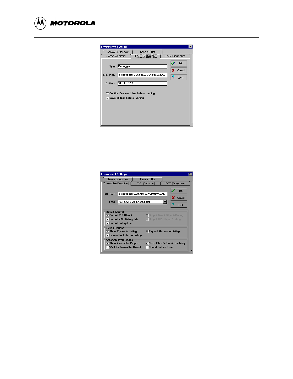
− Click on the EXE1 Debugger tab to bring the tab (Figure 1-1) to the front. Set
the executable type, path and filename, command line options (including
optional switches, filenames, or port settings), and other options for the
ICS05CW debugger application.
M68ICS05COM/D1-4
Page 17
INTRODUCTION
Figure 1-1. WinIDE Environment Settings Dialog EXE1 Tab
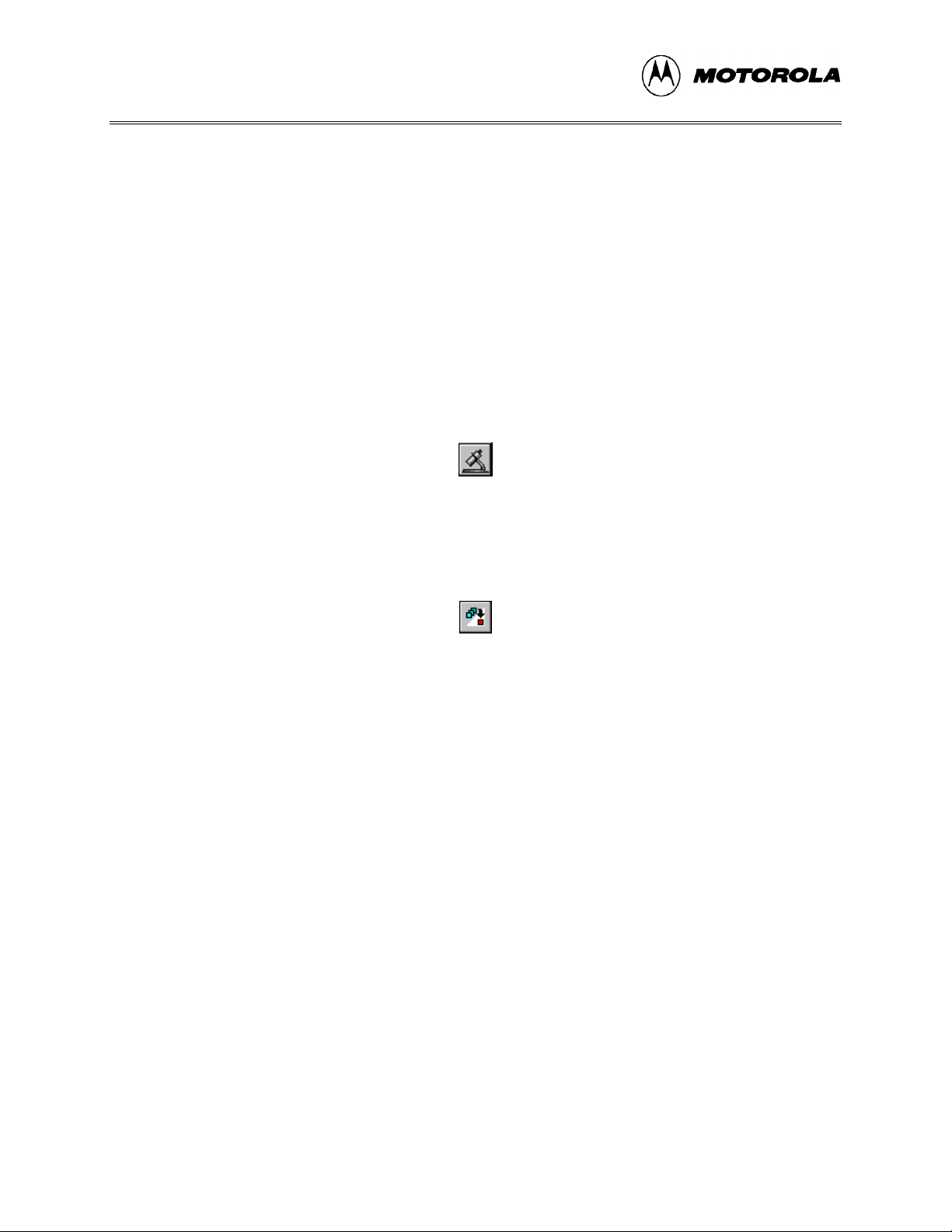
− Click on the Assembler/Compiler tab label to bring the tab (Figure 1-2) to the
front. Set the executable path and filename, type, and other options for the
CASM05W assembler or other application.
Figure 1-2. WinIDE Environment Settings Dialog Assembler/Compiler Tab
− If necessary, change the programmer settings in the EXE2 (Programmer) tab.
− Click on the General Environment and General Editor tabs and make changes
in each as necessary.
− When you have specified all the environment settings, press the OK button to
save the changes in the WINIDE.INI file and close the Environment Settings
dialog.
• Create a project file: The desktop and environment settings you make in the
Environment Settings dialog are stored in the WINIDE.INI file and read each time you
start the WinIDE editor. You may also choose to save project-specific desktop and
M68ICS05COM/D 1-5
Page 18
INTRODUCTION
environment settings in a project file (*.PPF) which is read when you open the
project, allowing you to save and use a general environment as well as custom
environments for individual projects. To create the project file:
• Run the ICS05CW simulator: With a project or source file open in the WinIDE
main window, click the Debugger (EXE1) button (Figure 1-3) on the WinIDE toolbar
to start the ICS05CW debugger and debug the contents of the active source window.
Additional information about the ICS05CW debugger can be found in Chapter 6 and
Chapter 7.
− Specify the project-specific desktop and environment settings in the WinIDE
editor.
− Choose the Save Project As option from the WinIDE Environment menu to
name and save the project to a directory folder.
Figure 1-3. The WinIDE Debugger Toolbar Button
• Assemble the code: Press the Assemble/Compile File button (Figure 1-4) on the
WinIDE toolbar to assemble the source code in the active WinIDE window.
Additional information about the CASM05W assembler can be found in Chapter 5.
Figure 1-4. The WinIDE Assemble/Compile File Toolbar Button
If you experience problems with the Quick Start procedures, refer to section B.3 for
troubleshooting instructions.
M68ICS05COM/D1-6
Page 19

POD INSTALLATION
CHAPTER 2
POD INSTALLATION
2.1 OVERVIEW
This chapter explains how to install the hardware components of the M68ICS05C in-circuit
simulator on your host PC in both interactive and standalone modes.
When the M68ICS05C pod is connected to the serial port of a host PC, you can use the actual
inputs and outputs of your target system during simulation of your source code. When the pod is
not connected to the PC, you can use the ICS05CW software as a standalone simulator.
2.2 INSTALLING THE M68ICS05C POD
Before beginning, locate these pod components:
• Hardware reset switch S3
• Power On switch S1
• 9-pin RS-232 serial connector P2
• 9 Volt Input Circular connector P1
To install the M68ICS05C Pod:
1. Connect the M68ICS05C pod to the serial port of your computer: attach the supplied
9-pin serial cable to the connector on the M68ICS05C board and attach the other end
to the host PC’s serial port.
2. Connect the 9-volt power supply: attach the power supply plug to the circular power
connector on the M68ICS05C pod and plug the power supply into a surge protection
device or wall outlet.
3. To run the ICS05CW software with actual input and output from the target device,
connect the M68ICS05C pod to the 40-pin DIP socket on the target board using the
40-pin ribbon cable included in the M68ICS05C kit. When this connection is
established and the pod and target system are started up, the target system will
provide inputs to and accept output from the ICS05CW software.
M68ICS05COM/D 2-1
Page 20

POD INSTALLATION
M68ICS05COM/D2-2
Page 21

SOFTWARE INSTALLATION AND INITIALIZATION
CHAPTER 3
SOFTWARE INSTALLATION AND INITIALIZATION
3.1 OVERVIEW
This chapter how to install and initialize the ICS05CW software.
3.2 THE ICS05CW SOFTWARE COMPONENTS
The ICS05CW software consists of the following components:
• WINIDE.EXE: the Windows Integrated Development Environment editor
• CASM05W.EXE: the 68HC05 Cross Assembler
• ICS05CW.EXE: the in-circuit Simulator, optimized for the HC05Cx-family Motorola
microcontrollers
3.2.1 The WinIDE Editor
The WinIDE editor is a text editing application that lets you use several different programs from
within a single development environment. Use the WinIDE editor to edit source code, launch a
variety of compatible assemblers, compilers, debuggers, or programmers, and configure the
environment to read and display errors from such programs.
If you select error detection options in the Environment Settings dialog, the WinIDE editor will
highlight errors in the source code, and display the error messages from the compiler or
assembler in the editor.
To debug source code in the WinIDE code window, load compatible source-level map files. You
can configure the CASM05W to produce such map files as an output.
Because the WinIDE editor is modular, you may, for example, choose to substitute a third party
C-compiler or other assembler for the CASM05W cross assembler provided in the toolkit.
3.2.2 CASM05W
The CASM05W is a cross assembler that creates Moto rola S19 object files and MAP files from
assembly files containing 68HC05 instructions.
M68ICS05COM/D 3-1
Page 22

SOFTWARE INSTALLATION AND INITIALIZATION
The CASM05W assembler has the same functionality as the DOS version of the assembler,
optimized to take advantage of the Windows graphical environment. Using the assembler in
conjunction with the WinIDE editor, you can edit standard ASCII files (such as the .ASM
assembly files), and use menu options and toolbar buttons to call other customized assemblers,
compilers, or debuggers. The resulting environment can allow assembled files to be downloaded
and tested while the original source code is modified and assembled, all without leaving the
WinIDE editing environment.
Paragraph 5-5 gives additional information about assembler options and how to use them.
3.2.3 ICS05CW
The ICS05CW is a simulator for HC705C series microcontrollers that can get inputs and outputs
(I/O) for the device when the external M68ICS05C pod is attached to the host computer. If you
want to use I/O from your own target board, you can attach the M68ICS05C pod to your board
through the extension cable that comes with the toolkit. You can also program HC05C devices
using the ICS05C board and ICS05CW software.
You can start or move to the ICS05CW in-circuit simulator software from the WinIDE editor.
The ICS05CW software can also be started using standard Windows techniques and run
independently of the WinIDE editor.
The ICS05CW simulator accepts standard Motorola S19 object code files as input for object code
simulation and debugging. If you are using a third party assembly- or C-language compiler, the
compiler must be capable of producing source-level map files to allow source-level debugging.
3.3 INSTALLING THE ICS05CW SOFTWARE
The ICS05CW software is supplied on two 3.5″ diskettes containing a setup program that
automatically installs the software on your hard drive.
3.3.1 Installation Steps
To install the software on your host computer’s hard drive, follow these steps:
1. Insert the ICS05CW diskette into the 3.5-inch disk drive.
For Windows 3.x: in the Program Manager, select Run from the File menu.
For Windows 95: from the Start Menu, select the Run option.
2. In the Run dialog, enter Setup (or click the Browse button to select a different drive
and/or directory) and press OK.
M68ICS05COM/D3-2
Page 23
SOFTWARE INSTALLATION AND INITIALIZATION
3. In the ICS05CW Microsoft Setup Wizard, follow the instructions that appear on the
screen.
NOTE
Select either the Typical Installation type to install the files to your
hard disk, or choose Compact Installation to copy the files to
another diskette.
Table 3-1 lists the files and directories required to control the ICS05CW program modules.
Table 3-1. The ICS05CW Software Files
Directory Filename Description
Casmw casm05w.exe Windows Cross Assembler for the 68HC05
ics05cw ics05cw.exe Windows In-Circuit Simulator
WinIDE winide.exe
Winide.hlp
Windows integrated Development Environment (WinIDE) program
file
Help for WinIDE
3.3.2 Starting the ICS05CW Software
Depending on the operating system you are using, choose the appropriate method for starting the
WinIDE software:
• From the Windows 3.x Program Manager, double-click the WinIDE and/or ICS05CW
icon(s).
• From the Windows 95 Start Menu, select the WinIDE and/or ICS05CW icon(s).
You can start the ICS05CW simulator alone or from within the WinIDE.
3.3.3 ICS Communication
When you double-click the ICS05CW icon, the software attempts to communicate with the pod
using the specified COM port, baud rate, and default parameters. When the software connects to
the pod, the Status Bar contains the message, "Contact with pod established."
If the pod is not installed, or the ICS05CW software cannot establish communications with the
pod through the specified COM port, the Can’t Contact Board dialog appears, with options for
changing the COM port or baud rate and retrying the connection, or choosing to run the simulator
in standalone mode (with no input or output from the pod).
M68ICS05COM/D 3-3
Page 24
SOFTWARE INSTALLATION AND INITIALIZATION
NOTE
The COM port assignment defaults to COM 1 unless you specify
another port in the startup command.
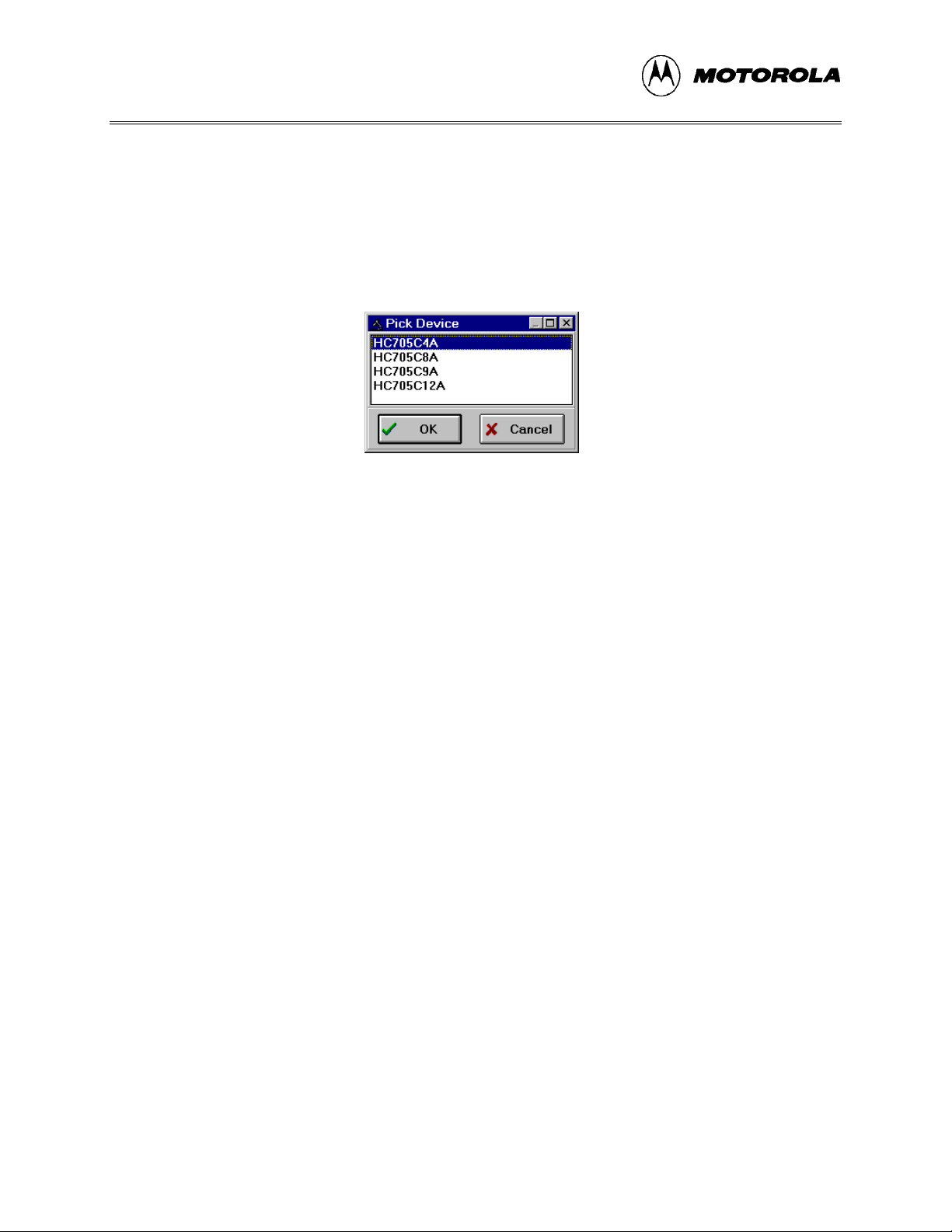
The first time you attempt to connect to the pod after installing the ICS05CW software, the
software asks you to select chip from the Pick Device dialog (Figure 3-1):
.
Figure 3-1. The Pick Device Dialog
To open the Pick Device dialog, enter the CHIPMODE command in the ICS05CW Status
Window command line.
M68ICS05COM/D3-4
Page 25

WinIDE USER INTERFACE
CHAPTER 4
THE WinIDE USER INTERFACE
4.1 OVERVIEW
This chapter is an overview of the WinIDE windows, menus, toolbars, dialogs, options, and
procedures for using each.
4.2 THE WINDOWS INTEGRATED DEVELOPMENT ENVIRONMENT
The Windows Integrated Development Environment (the WinIDE editor) is a graphical interface
for editing, compiling, assembling, and debugging source code for embedded systems using the
M68ICS05C In-Circuit Simulator.
The WinIDE interface consists of standard Windows title and menu bars, a WinIDE toolbar, a
main window containing any open source or project file windows, and a status bar. The WinIDE
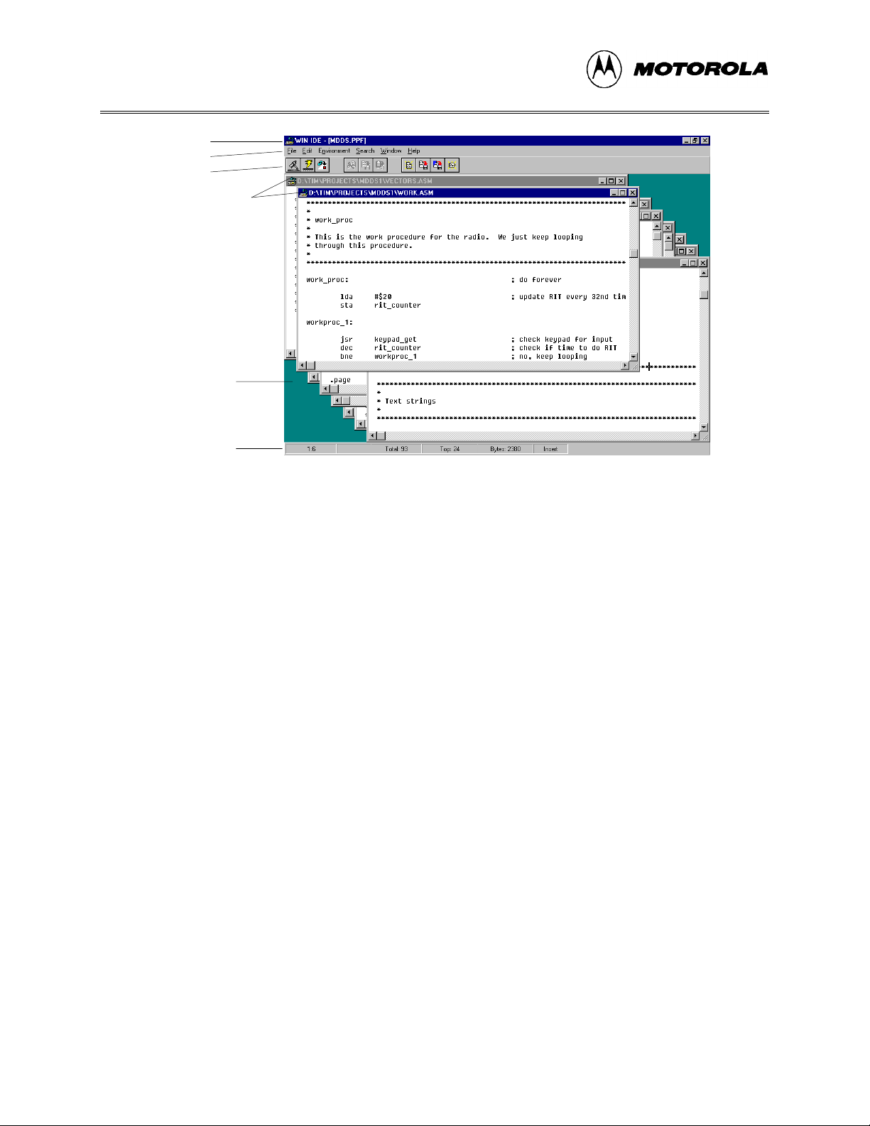
components are labeled in Figure 4-1 and described in paragraph 4.3.2.
M68ICS05COM/D 4-1
Page 26
WinIDE USER INTERFACE
Title Bar
Menu Bar
Toolbar
Source Windows
Main Window
Status Bar
Figure 4-1. WinIDE Window Components
4.3 WinIDE MAIN WINDOW
4.3.1 Main Window Functions
When you first start the WinIDE editor, the main window opens without any source or project
files. As you open or create source files or a project, they appear as subordinate windows in the
main window. You can move, size, and arrange subordinate windows using standard Windows
techniques and the WinIDE Window menu options.
Use the WinIDE main window to:
• Open, create, edit, save, or print source (*.ASM, *.LST, *.MAP, and *.S19) or project
(*.PPF) file.
• Configure the desktop and environment settings for the editor, assembler, compiler,
debugger, and other programs.
• Launch the in-circuit simulator, compiler, debugger, or another program.
4.3.2 Main Window Components
Figure 4-1 shows how the WinIDE main window might look during a typical editing project, and
labels the standard window components:
• Title Bar: The title bar appears at the top edge of the main window and contains:
M68ICS05COM/D4-2
Page 27
WinIDE USER INTERFACE
− The application title,
− The name of the target microcomputer application for which you are editing
source code,
− The object file or files, if any (usually truncated),
− Windows control buttons for closing, minimizing or maximizing the window.
• Menu Bar: The menu bar appears immediately below the title bar and contains the
names of the WinIDE menus.
• Toolbar: The WinIDE toolbar appears just below the menu bar and contains shortcut
buttons for frequently used menu options.
• Main Window: The main window area is the inside portion of the main window
which contains the open subordinate windows that you can resize, reposition,
minimize, or maximize using standard Windows techniques or Window menu
options.
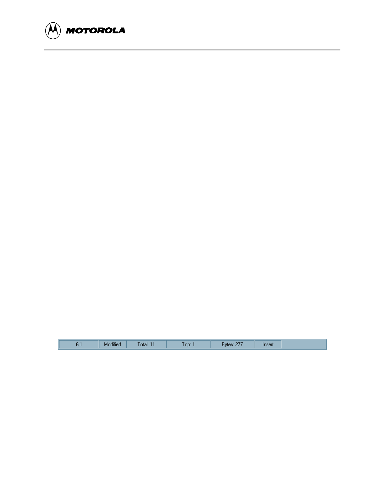
• Status Bar: The status bar (Figure 4-2) appears along the bottom edge of the main
window and contains a number of fields (depending on the project) that show:
− Source-file line and column numbers of the blinking insertion point cursor
− System status or progress of the current window; for example, when the
window is edited, the status will be Modified
− Total number of lines in the active window
− Top: the current line position in the file of the top of the active window
− Bytes: displays the total number of bytes in the active window
− Insert/Overwrite mode: indicates the current typing mode
The status fields expand and contract as client area contents change and files become
active.
4.4 GETTING STARTED
Figure 4-2. WinIDE Status Bar
4.4.1 Prerequisites for Starting the WinIDE Editor
Before you can start the WinIDE editor, the Windows operating environment must be running
and the ICS05CW software must be installed in the host computer.
M68ICS05COM/D 4-3
Page 28

WinIDE USER INTERFACE
Remember that for the M68ICS05C to run in simulation mode, the asynchronous
communications cable must connect the M68ICS05C pod on the platform board to the host
computer, and the power to the M68ICS05C pod must be on.
4.4.2 Starting the WinIDE Editor
To start the editor, select the WinIDE icon by double-clicking the ICS05CW Program Group
icon in the Windows 3.1 Program Manager or by selecting the icon from the Windows 95 Start
menu.
4.4.3 Opening Source Files
When the WinIDE editor opens, the main window is empty. To build the environment for your
project, choose the Open option from the File menu (or click the File button on the WinIDE
toolbar). In the Open File dialog, choose the files that will make up your project:
1. Select the drive containing the files from the Drives list.
2. Select the directory folder containing the files from the Folders list.
3. You may use the Filename text box to specify a filename or a wildcard/ extension to
filter the list of filenames (or choose a file type from the List files of type list). The
default file type is .ASM, but you can also choose:
*.c ( source code files)
*.lst (listing files)
*.txt (text files)
*.* (all files)
When all of the project files have been selected, click the OK button to open the files in the
WinIDE main window.
4.4.4 Navigating in the WinIDE Editor
To navigate among subordinate windows:
To navigate among the several sub-windows in which your project files are displayed in the
WinIDE main window:
• Choose the subordinate window’s filename from the Window menu or click on the
file’s title bar to bring it to the front of the cascaded stack.
• If you have a large screen or a few project files, you may choose the Tile option from
the Window menu to lay out all of the sub-windows so that all are visible, or choose
M68ICS05COM/D4-4
Page 29
WinIDE USER INTERFACE
the Cascade option to arrange all windows so that only the top window is entirely
visible.
• Regardless of how you arrange the windows, the title bar of all windows are visible.
To move between the WinIDE editor and the ICS05CW simulator:
• From the WinIDE editor, click the External Program 1 toolbar button to switch
to the in-circuit simulator or the application which you have specified as the debugger
or other external program to use.
• From ICS05CW, click the Back to Editor toolbar button to toggle back to the
editor.
4.4.5 Using Markers
Markers provide a convenient way to mark multiple points in a file for navigating between
frequently visited locations while you are editing. You can set as many as 10 markers in source
files in the WinIDE editor. A marker appears in the file as a small button labeled with the marker
number.
When you save the project, the WinIDE editor saves the markers for all open edit files as well, so
that when you open the project again, the markers are still set.
To set a marker anywhere in the file:
1. Place the cursor on the line where you want the marker to be.
2. Press CNTL + SHIFT + N, where N is a value from 0 to 9 indicating the marker
number. A marker appears at the far left of the line.
To move to a marker, press CNTL + N, where N is denotes a marker number between 0 and 9.
This feature is useful if you are editing a large file.
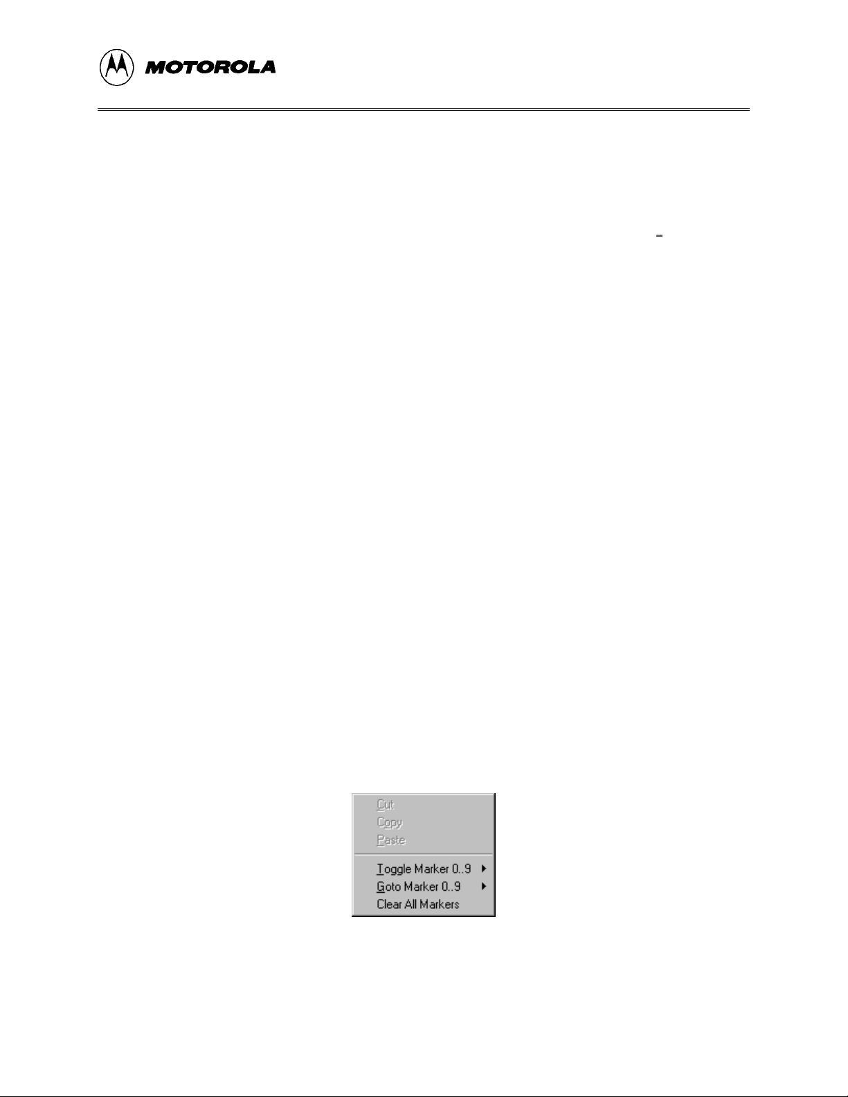
Markers can also be set, changed, navigated to, or cleared using options on the Edit shortcut
menu (Figure 4-3). Open the Edit shortcut menu by clicking the right mouse button in any edit
window.
Figure 4-3. Edit Shortcut Menu
M68ICS05COM/D 4-5
Page 30
WinIDE USER INTERFACE
To set or clear a marker using the Edit shortcut menu options:
1. With the cursor in any editing window, click the right mouse button to open the
shortcut menu.
2. Position the cursor on the line where the marker should appear. Click the right mouse
button to display the shortcut menu.
3. Click the Toggle Marker 0-9 option to open the list of markers.
4. Click once on the marker to toggle. When the marker number is checked, it is toggled
on; when the marker number is unchecked, it is toggled off.
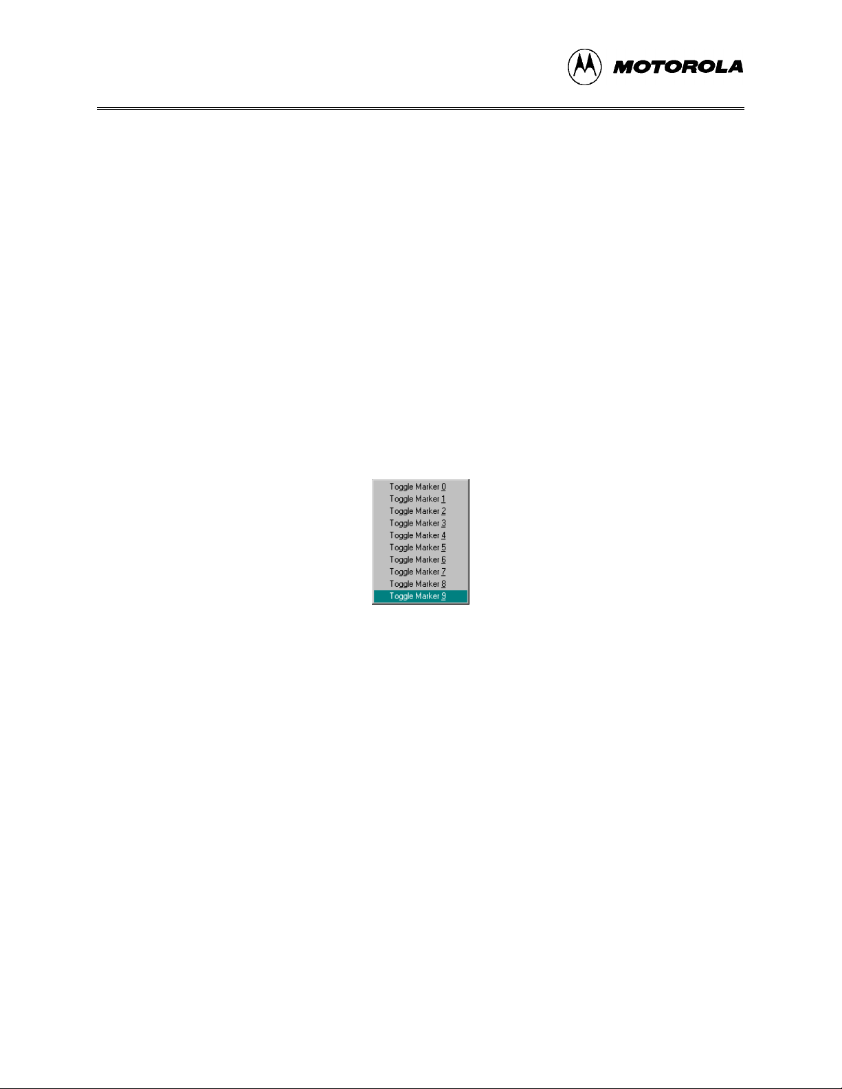
To move to a marker number using the shortcut menu options:
1. With the cursor anywhere in the edit file, click the right mouse button to open the Edit
shortcut menu .
2. Click on the Go T o Marker 0-9 option to open the Marker sub-menu (Figure 4-4), and
choose the marker number to move to.
Figure 4-4. Marker Sub-menu
You can execute many ICS05CW menu options using either keyboard commands or toolbar
buttons. For example, to move to a marker, press the Ctrl + Shift + N key combination, where N
is the marker number).
4.5 COMMAND-LINE PARAMETERS
The WinIDE editor lets you specify command line options to pass to each executable program.
The name of the currently edited file, or some derivative thereof, can be passed within these
options. To pass the current filename, specify a parameter %FILE%. The WinIDE editor will
substitute this string with the current filename at execution time. You may also change the
extension of the passed filename, by specifying it within the %FILE% parameter. For example,
to specify an .S19 extension on the current filename the user would specify a %FILE.S19%
parameter.
M68ICS05COM/D4-6
Page 31

WinIDE USER INTERFACE
For example, if the current filename being edited is MYPDA.ASM:
Parameters passed to
Parameters specified
%FILE% S L D MYPDA.ASM S L D
%FILE.S19% 1 @2 MYPDA.S19 1 @2
program
Although it is by default the currently edited filename that is used in the %FILE% parameter
substitution, the environment can be configured always to pass the same filename. Do this by
checking the Main File option in the Environment Settings dialog’s General Options tab. This
technique is useful if you want to pass a specific filename to the external program without regard
to what is being edited.
4.6 WinIDE TOOLBAR
The WinIDE Toolbar (Figure 4-5) provides a number of convenient shortcut buttons that
duplicate the function of the most frequently used menu options. A tool tip or label pops up when
the mouse button lingers over a toolbar button, identifying the button’s function.
Figure 4-5. WinIDE Toolbar
Table 4-1 identifies and describes the WinIDE toolbar buttons.
M68ICS05COM/D 4-7
Page 32

WinIDE USER INTERFACE
Table 4-1. WinIDE Toolbar Buttons
Icon Button Label Button Function
External Program 1
(Debugger)
External Program 2 Call the External Program 2 as specified in
Assemble/Compile File Assemble or compile the active source window .
Cut Cut the selected text from the active source window (this
Copy Copy the selected text in the active source window to the
Paste Paste the contents of the Windows clipboard at the
Open File Close the active source window (this button is a shortcut
Call the External Program 1 (Debugger or ICS) specified
Environment Settings
in the
tab; this could be the debugger (by default), the ICS or
other external program, i.e., third party assembler,
debugger, or compiler.
dialog’s
EXE 1 (Debugger)
the
Environment Settings
button is a shortcut for the
Windows clipboard (this button is a shortcut for the
menu option).
Copy
insertion-point location in the active source window (this
button is a shortcut for the
for the
File - Open
dialog’s
menu option).
EXE 2 (Programmer)
Edit - Cut
Edit - Paste
menu option).
menu option).
tab
Edit -
Save File Save the file in the active source window (this button is a
shortcut for the
Save Project (All Files &
Setup)
Close File Close the active source window (this button is a shortcut
Save the active project (this button is a shortcut for the
Environment - Save Project As
for the
File - Close
File - Save
menu option).
menu option).
menu option).
M68ICS05COM/D4-8
Page 33

4.7 WinIDE MENUS
Table 4-2 summarizes WinIDE menu titles and options.
Table 4-2. WinIDE Menus and Options Summary
Menu Title Option Description
File New File Open a new file window ("No name")
WinIDE USER INTERFACE
Open File Display the
Save File Save the current file
Save File As Open the
in which to save the current file
Close File Close the current file
Print Open the
Print Setup Open the
Exit Close the WinIDE editor
Edit Undo Undo the last action
Redo Redo the last action
Cut Cut the selection to the clipboard
Copy Copy the selection to the clipboard
Paste Paste the contents of the clipboard
Delete Delete the selection
Open File
Save As
Print
dialog to print the current file
Print Setup
dialog to choose a file to open
dialog to choose a directory and filename
dialog to choose printer options
Select All Select all text in the current window
M68ICS05COM/D 4-9
Page 34

WinIDE USER INTERFACE
Table 4-2. WinIDE Menus and Options Summary (continued)
Menu Title Option Description
Environ-
Open Project Open the
ment
Save Project Save the current project
Save Project
Open the
As
Close/New
Project
Close the current project file or open a new project file if no
current file
Setup Open the
- General Environment
- General Editor
- Environment Settings
- Debugger Settings
Setup Font Open the
current file
Search Find Open the
Replace Open the
string
Find Next Go to the next occurrence of the search string
Specify Project File to Open
Specify Project File to Save
Environment Settings
Font
dialog to specify font options for the text in the
Find
dialog to enter a search string
Replace
dialog to enter a search and replacement
Dialog to change settings for:
dialog
dialog
Go to Line Open the
Go to Line Number
dialog and enter a line number
to go to in the current file
Window Cascade Cascade open windows with active window on top
Tile Tile open windows with active window on top
Arrange Icons Arrange minimized window icons along the bottom edge of
the main window
Minimize All Minimize all open windows
Split Toggle a split window in the active file
Windows (by
name)
Itemize the open and minimized windows by name in order of
opening
Help Contents Opens the WinIDE Help Contents Page of the Help File
About Displays the WinIDE About Window
M68ICS05COM/D4-10
Page 35

WinIDE USER INTERFACE
4.8 WinIDE FILE OPTIONS
This section describes the WinIDE File menu options for managing and printing source files or
exiting the WinIDE editor.
To select a File option, click once on the File menu title to open the File menu (Figure 4-6). Click on an
option to perform the operation. You may also use accelerator or shortcut keystrokes to execute
the option.
Figure 4-6. File Menu
4.8.1 New File
Choose New File from the File menu to open a new client window in the WinIDE main window.
The title of the new window in the title bar defaults to [NONAME#], where # reflects the number
of new source windows created during this session. If there is an active project, the project name
appears in the title bar. If there is no project, [No Project] precedes the window name.
Use this new window to enter source code. When you save the contents of this window, the
WinIDE editor prompts you for a new filename. This new filename replaces the [NONAME#] in
the title bar.
Alternatives: Type Ctrl + N or click the New toolbar button. This is the keyboard equivalent to
choosing the File - New File menu option.
M68ICS05COM/D 4-11
Page 36

WinIDE USER INTERFACE
4.8.2 Open File
Choose Open File from the File menu to open the Open File Dialog (Figure 4-7) and choose an
existing filename, file type, directory, and network (if applicable) to open.
Figure 4-7. Open File Dialog
Each file opens in its own client window within the main WinIDE window.
Alternatives: Type Ctrl + O or click the Open button on the toolbar. This is the keyboard
equivalent to choosing the File - Open File menu option.
4.8.3 Save File Choose Save File from the File menu to save the file in the active source window.
• If you are saving the file for the first time (that is, it has not yet been named), the Save
As dialog appears. Enter a new filename for the file and accept the current fil e type,
directory or folder, and drive, or choose new options. Press the OK button to save the
file to the selected drive/directory.
• If the file has been saved previously (and has a name), the file is saved with the
filename, in the directory and drive previously specified, and the source window
remains open.
Alternatives: Type Ctrl + S or click the Save button on the toolbar. This is the keyboard
equivalent to choosing the File - Save File menu option.
4.8.4 Save File As
Choose Save File As from the File menu to save the contents of the active source window and
assign a new filename. The Save As dialog opens. Enter a new file name in the File Name field
and click the OK button to save the file and return to the source window.
M68ICS05COM/D4-12
Page 37

WinIDE USER INTERFACE
To save the file with the name of an existing file, select the filename in the File Name list, and
click the OK button. A confirmation dialog will ask you to confirm that you want to overwrite
the existing file.
4.8.5 Close File
Choose Close File from the File menu to close the file in the active source window.
If you chose the Give user option to save each file option in the General Environment tab in the
Environment Settings dialog, the Information dialog will display, reminding you to save changes
to the .ASM file.
Alternatives: Type Ctrl + D or click the Close toolbar button. This is the keyboard equivalent to
choosing the File - Close File menu option.
4.8.6 Print File
Choose Print from the File menu to open the Print dialog (Figure 4-8) and choose options for
printing the active source window.
The Print dialog for your operating system and printer capabilities opens for you to choose Print
range, Print quality, and open the Print Setup dialog to change printer settings.
Figure 4-8. Print Dialog
NOTE
The Print option is active when at least one source window is
open. The WinIDE editor disables the option if no window is open.
M68ICS05COM/D 4-13
Page 38

WinIDE USER INTERFACE
4.8.7 Print Setup
Choose the Print Setup option from the File menu to open the Print Setup dialog for your operating system and printer. Use this dialog to choose the printer, page orientation, paper size, and other options for your printer.
4.8.8 Exit
Choose the Exit option from the File menu to close the editor. If a project or source window is open, the editor closes the files and exits.
Alternatives: Type Alt + F4. This is the keyboard equivalent to choosing the File - Exit menu
option.
4.9 WinIDE EDIT OPTIONS
This section describes the WinIDE Edit menu options for creating or editing source file contents.
To perform an Edit operation, click once on the Edit menu title to open the Edit Menu
(Figure 4-9). Click on an option to perform the operation.
Figure 4-9. Edit Menu
4.9.1 Undo
Choose Undo to undo or reverse the last action or change you made in the active source window.
Changes that you make to the contents of the window (and that are undoable or reversible) are
saved in an undo stack, where they accumulate, up to a maximum of 20 instances. You can reverse your changes in descending order of the sequence in which they were made. If no more changes remain in the stack, the Undo option is disabled.
Reversible actions are local to each source window. Commands that are not reversible do not
contribute to the undo stack. You cannot, for example, undo the command to open a new window
using the Undo command.
Alternatives: Type Ctrl + Z. This is the keyboard equivalent to selecting the Edit - Undo menu
option.
M68ICS05COM/D4-14
Page 39

WinIDE USER INTERFACE
4.9.2 Redo
Choose Redo to restore the most recently undone action in the active window.
The Redo option restores actions undone or reversed by the Undo option, in ascending order, that
is, last action first. Reversible changes to the window’s contents accumulate in the window’s undo stack. Once a change has been reversed using the Undo option, the change can be reversed, using the Redo option When no more changes remain (that is, the top of the Redo stack is reached) the Redo option is disabled.
Some commands are not reversible: they do not contribute to the undo stack and therefore cannot
be redone. For instance, since reversible actions are local to each source window, opening a new
window is an action that cannot be undone using the Undo command, or redone using the Redo
command.
NOTE
The Redo option is active only if you have used the Undo option to
modify the contents of the active source window.
Alternative: Type Shift + Ctrl + Z. This is the keyboard equivalent to selecting the Edit - Redo
menu option.
4.9.3 Cut
Choose Cut from the Edit menu to cut the currently selected text from the active source window
and place it on the system clipboard.
NOTE
The Cut option is active only when you have selected text in the
active source window.
Alternative: Type Ctrl + X. This is the keyboard equivalent to selecting the Edit - Cut menu
option.
4.9.4 Copy
Choose Copy from the Edit menu to copy the selected text from the active source window to the
Windows clipboard.
NOTE
The Copy option is available only if you have selected text in the active source window.
M68ICS05COM/D 4-15
Page 40

WinIDE USER INTERFACE
Alternatives: Type Ctrl +C or click the Copy toolbar button. This is the keyboard equivalent to
selecting the Edit - Copy menu option.
4.9.5 Paste
Choose Paste from the Edit menu to paste the contents of the Windows clipboard into the active
source window at the insertion-point location.
Alternatives: Type Ctrl + V or click the Paste button on the toolbar. This is the keyboard equivalent to selecting the Edit - Paste menu option.
4.9.6 Delete
Choose Delete from the Edit menu to delete the selected text from the active source window without placing it on the Windows clipboard. Text you delete using the Delete option can be restored only by using the Undo option.
Alternatives: Press the Delete key. This is the keyboard equivalent to selecting the Edit - Delete
menu option.
4.9.7 Select All Choose Select All from the Edit menu to select all text in the active source window.
4.10 WinIDE ENVIRONMENT OPTIONS
This section describes the WinIDE Environment menu options for managing project information,
and setting up environment and font settings for a project.
Environment settings represent the current environment and configuration information for the
WinIDE editor. These settings are stored in the WINIDE.INI file, from which they are loaded
each time you start the editor, and saved each time you exit from the editor.
When you start the editor, the application opens the WINIDE.INI file and reads the project
information. If there is an open project, the project file’s environment settings are read and used
instead. This lets you have different environment configurations for different projects.
Environment information stored in the WINIDE.INI file includes:
• If a project is open, its name
• Current font information
• Current source directory and project directory paths
M68ICS05COM/D4-16
Page 41

WinIDE USER INTERFACE
• The preferences and options you set in the Environment Settings dialog tabs,
including:
− General Environment options
− General Editor options
− Executable options for assembler, debugger, compiler, and programmer
To choose an environment option, click once on the Environment menu title (Figure 4-10) to open the
menu. Click on the option to execute.
Figure 4-10. Environment Menu
Project files have the extension .PPF; they store two kinds of information:
• Environment Settings: User settings and WinIDE configuration parameters
• Desktop Information Open edit windows, size and location, markers
4.10.1 Open Project
Choose Open Project from the Environment menu to choose the project file in the Specify project file to open dialog (Figure 4-11).
Figure 4-11. Specify project file to open Dialog
1. Enter the project name in the File name: text box or select the project name from the
list box below.
2. Press the OK button to open the new project file (or press the Cancel button to close
the dialog without opening a file).
M68ICS05COM/D 4-17
Page 42

WinIDE USER INTERFACE
4.10.2 Save Project
Choose Save Project from the Environment menu to save the current project in the currently
specified file and pathname.
4.10.3 Save Project As
Choose Save Project As from the Environment menu to display the Specify project file to save dialog (Figure 4-12).
Figure 4-12. Specify project file to save Dialog
1. Enter the project name in the File name: text box or select the project name from the
list box below.
2. Press the OK button to open the new project file (or press the Cancel button to close
the dialog without opening a file).
4.10.4 Close/New Project Choose Close/New Project from the Environment menu to:
• Close an active current project file
• Open a new project
4.10.5 Setup Environment
Choose Setup Environment from the Environment menu to display the Environment Settings
dialog box.
The Environment Settings dialog contains five tabs:
• General Environment
• General Editor
• Assembler/Compiler
M68ICS05COM/D4-18
Page 43

WinIDE USER INTERFACE
• EXE 1 (Debugger)
• EXE 2 (Programmer)
In th e Environment Settings tabs, you can choose options by marking option buttons (sometimes
called radio buttons), check boxes, and entering information in text boxes.
4.10.5.1 The General Environment Tab
Click the General Environment tab in the Environment Settings dialog (Figure 4-13) to change
options for saving the project files, exiting the WinIDE editor, and storing a filename to be
passed to an external program as a parameter.
Figure 4-13. Environment Settings Dialog
General Environment Tab
NOTE
Clicking the OK button on any tab saves all changes made in the
Environment Settings dialog and closes the dialog.
The General Environment Tab offers these options:
• Upon Exiting the WinIDE Editor
− Auto-Save the Current Proj ect: Select this option to save the currently open
project automatically, with the file extension .PPF, without prompting. The
editor saves all currently open files with the current project. If you do not
select this option, the editor prompts you to save the open project when you
exit. This setting only has an effect if a project is open when you exit.
M68ICS05COM/D 4-19
Page 44

WinIDE USER INTERFACE
− Auto-Save All Files: Select this option to save all open editor files
automatically, without prompting, when you exit. If you do not select this
option, the editor will prompt you to save open files when you exit.
− Ask user "Exit Application Select this option to display an Exit Application
confirmation message when you exit. If you do not select this option, the
editor will close without asking for confirmation when you choose the Exit
option from the File menu.
• Saving the Project
− Also save all open editor files: Select this option to save all open editor files
whenever you save the project file. If you do not select this option,
project/environment information is written to the project files, but editor files
are not saved when you choose the Save Project option from the Environment
menu.
• %FILE% Parameter passed to executable programs is: The %FILE% parameter
specifies what is passed on the command line in place of the %FILE% string. You
may specify the %FILE% string as a command line parameter for executable
programs launched from within the WinIDE editor.
− Currently edited filename: Select this option to use the name of the current
active file (the window with focus) as the %FILE% parameter substitution.
− Main Filename: Select this option to use the filename in the Main filename
edit box as the %FILE% parameter substitution.
If you are using include files, you must enter the full pathname of
the file containing the included files in the Main filename edit box.
• If Modified files exist just prior to external program execution: All executable
programs which you can launch from the WinIDE editor offer the option to save all
open editor files before the executable is launched.
− Give user option to save each file: Select this option if you want to be
prompted to save each modified file before the external program is launched.
If you do not select this option, the external program runs without asking for
your confirmation. The result may be that an external program runs while
modified files exist in the editing environment, a circumstance that may be
undesirable and lead to incorrect results.
4.10.5.2 General Editor Tab
NOTE
Click the General Editor tab in the Environment Settings dialog (Figure 4-14) to bring the
General Editor tab to the front. Use the General Editor tab to change editing options such as
indentation, word wrap, and tab settings.
M68ICS05COM/D4-20
Page 45

WinIDE USER INTERFACE
NOTE:
To change font options, choose the Setup Font option from the
Environment menu.
Figure 4-14. Environment Settings Dialog:
• General Options
− Auto-Indentation: Select this option to place the cursor in the column of the
first non-space character of the previous line when the Enter key is pressed. If
this option is not checked, the cursor goes to the first column. For example, if
the current line begins with two tab spaces, pressing the Enter key will begin
the next line with two tab spaces, aligning the new line under the first text of
the previous line.
− Create Backup: Select this option to create a backup file whenever a file is
saved. The WinIDE editor will copy the current disk version of the file (the
last save) to a file of the same name with the .BAK extension, then save the
current edited copy over the editing filename. The default (and recommended)
setting for this option is "on," giving you the option to return or review the
previous version of the file. If you do not select this option, the currently
edited file will be saved, but no backup will be made.
• Word Wrap
− Wrap to Window: Select this option to have the cursor to wrap to the left
when it reaches the far right side of the window. This lets you see all the text
in the file, without scrolling the line. If you do not select this option, text
wraps only when you press the Enter key.
General Editor Tab
− Wrap to Column: Select this option to wrap text to the left side when the
cursor reaches a specified column. This lets you see all the text in the file,
M68ICS05COM/D 4-21
Page 46

WinIDE USER INTERFACE
without scrolling the line. Set the column number at which text wrapping
should occur in the edit box to the right of this option.
− Word Wrap OFF: Select this option to turn text wrapping off. To view or edit
text, which does not fit horizontally in the window, use the scroll controls. In
general, this option should be on when you are writing or editing code.
• Tab Settings
− Fixed Tabs: Select this option to use spaces to emulate t abs: pressing the tab
key inserts a number of spaces to bring the cursor to the position of the next
tab stop. Changing the tab size affects only future tab spacings. Past tabs
remain unchanged.
− Real Tabs: Select this option to use actual tab characters: pressi ng the tab key
insets a tab character. The tab character is displayed as a number of spaces
determined by the tab size, but is really a tab character. Changing the tab size
affects the display of all tabs in the file, present and future.
− Smart Tabs: Select this option to enable smart tabs:
♦ If the previous line contains text, pressing the tab key advances the
cursor to the same column as the beginning of the next character group
on the previous line.
♦ If the previous line does not contain text, smart tabs behave as fixed
tabs.
− Tab Size: Enter the number of spaces in a tab. This setting affects how all tabs
operate: fixed, real, or smart tabs. This number is the default display size of all
tab characters, and the size in spaces of a tab in both fixed and smart modes. If
the tab size is N, the tab stops are at 1, N+1, 2N+1, 3N+1, and so on.
4.10.5.3 Assembler/Compiler Tab
In addition to running an external compiler, you may need to run other external programs such as
third party programmers, debuggers, or simulators. The WinIDE editor lets you configure as
many as three external programs: two general-purpose programs and one compiler. Use the
settings on the Assembler/Compiler tab of the WinIDE Environment Settings dialog to set up
external programs.
Click the Assembler/Compiler tab heading in the Environment Settings dialog (Figure 4-15) to
bring the tab to the front. Use the options on this tab to change the settings and parameters for the
assembler or compiler path and type, and specify output, listing, and assembly preferences.
• EXE Path: Enter the full path and executable name of the compiler in the text box.
The extensions EXE/COM/BAT are legal. For a DOS executable or BATch file, you
may want to create a PIF file to prevent the screen from changing video modes when
the executable runs.
M68ICS05COM/D4-22
Page 47

WinIDE USER INTERFACE
Figure 4-15. Environment Settings Dialog:
Assembler/Compiler Tab
• TYPE: Click on the downward-pointing arrow to the right of the Type list box to
display the compiler types. Click on the compiler type to select it. The options in the
Assembler/Compiler tab change according to the compiler type chosen:
− If you select the P&E compiler, a number of compiler options are available.
− If you select a non-P&E compiler, options lets you specify the parameters to
pass the compiler.
• Output Control: These options specify the output files that the assembler will create:
− Output S19 Object: Select this option to have the assembler output an S19
object file. The S19 object file contains the compiled instructions from the
program assembled. The output S19 file has the same name as the assembly
file, but with the .S19 extension. Appendix A: S-Record Information gives
more information about the S19 file format.
− Output Debug File: Select this option to have the assembler produce a debug
.MAP file. The debug .MAP file contains symbol information as well as line
number information for source level debugging from the program assembled.
The output debug file has the same name as the assembly file, but with the
.MAP extension.
− Output Listing File: Select this option to have the assembler produce a listing
file. The listing file shows the source code as well as the object codes that
were produced from the assembler. Listing files are useful for debugging, as
they let you see exactly where and how the code assembled. The output listing
file has the same name as the assembly file, but with the .LST extension.
M68ICS05COM/D 4-23
Page 48

WinIDE USER INTERFACE
• Listing Options: The following options specify how the assembler generates the
listing file.
− Show Cycles in Listing: Select this option to include cycle information for
each compiled instruction in the listing (.LST) file. View the cycle information
to see how long each instruction takes to execute. The cycle count appears to
the right of the address, enclosed in brackets.
− Expand Includes in Listing: Select this option to expand all include files into
the current listing file. This lets you view all source files in a main listing file.
If this option is not checked, you will see only the $Include statement for each
included file, not the source file.
− Expand Macros in Listing: Select this option to expand all macros into the
listing file: each time the macro is used, the listing will show the instructions
comprising the macro. If you do not select this option, you see only the macro
name, not its instructions.
• Assembly Preferences
− Show Assembler Progress: Select this option to display a pop-up window
showing the current assembly status, including:
♦ The pass the assembler is currently on
♦ The file that is currently being assembled
♦ The line that is currently being assembled
If this option is not checked, you must wait for the assembly result to be
displayed on the status bar at the bottom of the environment window.
− Wait for Assembler Result: Select this option and the Show Assembler
Progress option to cause a progress window displaying the assembly result to
stay up when assembly is done. The assembly result window will remain until
you dismiss it by clicking the OK button. In general, do not select this option,
as the assembler results are shown in the status bar at the bottom of the
WinIDE window.
− Save files before Assembling: Select this option to save all open files to disk
before you run the assembler. This is important because the
assembler/compiler reads the file to be compiled from the disk, not from the
open windows in the WinIDE editor. If you do not save the file before
assembling it, the assembler will assemble the last saved version. In general,
you should leave this option checked.
− Sound Bell on Error: Select this option to have the assembler beep if it
encounters an error.
M68ICS05COM/D4-24
Page 49

WinIDE USER INTERFACE
• Other Assembler/Compiler: If you choose Other Assembler / Compiler from the
Type list, the WinIDE editor offers these additional options:
− Options: Enter the options to pass to the compiler on the command line. Such
options generally consist of switches that instruct the compiler, and a
filename. Enter the %FILE% string in the command line to insert either the
current filename or the filename specified in the Main Filename option in the
EXE Path text box of the General Environment tab options (Figure 4-13).
− Confirm command line: Select this option to display a window describing the
executable you want to run, and the parameters that you want to pass to the
executable, just before the assembler/compiler is run. This gives you the
option to cancel the assemble/compile, continue as described, or modify
parameters before you continue with the assembly. If you do not select this
option, the assembler/compiler runs without prompting you to confirm
parameters.
− Recover Error from Com piler: Select this option to have the WinIDE editor
attempt to recover error/success information from the assembler/compiler, and
open the file with the error line highlighted (and displayed in the status bar)
when an error is encountered. For this feature to work, the Error Filename and
Error Format options must also be set in this tab. If this option is not checked,
the WinIDE editor will not look for a compiler result and will not display the
results in the status bar.
− Wait for compiler to finish: Select this option to have the WinIDE editor
disable itself until the compiler terminates. You must select this option for the
editor to attempt to recover error/success information from the assembler/
compiler. Further, turning this option on prevents you from running external
programs from the editor that may require compilation or assembly results. If
you do not select this option, the editor starts the assembler/compiler, and
continues, letting Windows’ multitasking capabilities take care of the program.
− Save files before Assembling: Select this option to save all open files to disk
before the running the assembler. This can be very important since the
assembler/compiler reads the file to be compiled from the disk and not from
the memory of the WinIDE editor. If the file being assembled isn’t saved, the
assembler or compiler will assemble the last saved version. For this reason,
you should leave this option checked.
M68ICS05COM/D 4-25
Page 50

WinIDE USER INTERFACE
• Error Format: Click the down arrow to the right of the Error Format list box to
display the list of error formats (Figure 4-16). If the WinIDE editor is to attempt to
read back an error from a compiler, it must understand the error syntax. This option
lets you select an error format from a list of supported formats. If the Recover Error
from compiler option is checked, and the filename specified in the Error Filename
text box is found, the editor parses that file from end to beginning looking for the
error. If the editor finds an error, it opens the file, highlights the error line, and
displays the error in the status bar.
• Error Filename: Enter the filename to which the editor pipes the compiler/assembler
error output. Some compilers provide a switch for piping error output to a file; others
require that you handle this manually. As most compilers are DOS-based, you can
create a batch file into which to pipe the output. For example:
Figure 4-16. Error Format List
COMPILER OPTIONS > ERROR.TXT
This batch file creates the file ERROR.TXT and sends the assembler/compiler output to
that file. Most C-compilers require a batch file to run the compiler through its various
steps (compiling, linking), to which you may add a pipe for error output.
Once the environment reads this error file, the WinIDE editor displays the results, and
the deletes the error file. If you want to keep a copy of the file, you must add such
instructions to the batch file.
4.10.5.4 Executable 1 (Debugger) and Executable 2 (Programmer) Tab
Choose either the EXE 1 (Debugger) tab or the EXE 2 (Programmer) tab (Figure 4-17) in the
Environment Settings dialog to bring either tab to the front. Enter options for the general-purpose
external programs, for example, the ICS05CW, that you will be using with this project.
M68ICS05COM/D4-26
Page 51

WinIDE USER INTERFACE
Figure 4-17. Environment Settings Dialog:
EXE 1 (Debugger) and EXE 2 (Programmer) Tabs
NOTE
The options are the same in both tabs.
• Type: Enter a description of the executable type in the Type text box. This string will
appear in other parts of WinIDE editor. The default for Executable 1 is Debugger. For
the ICS05CW, you may choose to change the Type to ICS. This will change the label
on this tab and elsewhere in the dialog.
− EXE Path: Enter the full path and executable name of Executable 1 in the
EXE Path text box. The executable name may have an EXE, COM, or BAT
extension. For a DOS-based executable or batch file, you may choose to create
a PIF file to prevent the screen from changing video modes when the file is
run.
− Options: Enter the options you want to pass to the executable on the command
line in the Options text box. In general, options will consist of switches that
instruct the executable from the command line. You may add a filename using
the %FILE% string. The %FILE% string inserts either the currently active
filename, or the filename specified by the %FILE% parameter, set in the
%FILE% parameters to pass to external programs field in the General
Environment tab.
M68ICS05COM/D 4-27
Page 52

WinIDE USER INTERFACE
− Confirm Command line before running: Select this option to display a
window describing the executable to be run and the parameters which will be
passed, just before the assembler/compiler is run. This gives you the option to
cancel the assemble/compile, continue as described, or modify parameters
before continuing. If you do not select this option, the assembler/compiler will
be run without prompting you to confirm parameters.
− Save all files before running: Select this option to save all open files to disk
before running the executable. This is important since external programs that
must read the edit file read only the last version saved to disk. In general,
always select this option.
− Wait for program completion: Select this option to have the WinIDE editor
disable itself until the executable terminates. If you do not select this option,
the editor starts the compiler, and allows Windows to manage the program.
4.10.6 Setup Fonts
Select the Setup Fonts option in the Environment menu to open the Setup Fonts dialog (Figure 4-
18) to change font options in the editor.
Figure 4-18. Setup Fonts Dialog
• Font: The Font text box displays the name of the current font. To change the current
font, select another font name from the Font list. Use the scroll arrows if necessary to
view all the font choices.
• Font Style: The Font Style text box displays the name of the current font style. To
change the current font style, select another font style name from the Front Style list.
• Size: The Size text box displays the current font size. To change the size, enter a new
number in the text box or choose a font size from the list.
M68ICS05COM/D4-28
Page 53

• Effects: Toggle special font effects:
− Strikeout: Choose this option to produce a horizontal strike-through line in
the selected text
− Underline: Choose this option to produce a horizontal underscore line below
the selected text
• Color: Choose the text color from the drop-down list box. Click on the downward
pointing arrow to display the Color list. Use the scrolling arrows to view all of the
choices, if necessary.
• Sample: As you choose Font options, an example of the text that will result is shown
in the Sample area.
• Script: If you have installed multilingual support, use this option to choose a non-
western script.
4.11 WinIDE SEARCH OPTIONS
WinIDE USER INTERFACE
This section describes the WinIDE Search menu options for specifying search criteria and
entering a line number to go to in a source file.
To perform a search operation, click once on the Search menu to open the menu (Figure 4-19).
Click on the option to execute.
Figure 4-19. Search Menu
4.11.1 Find
Choose the Find option from the Search menu to open the Find dialog (Figure 4-20). In the Find
what: box, enter the string to search for. The search will be performed in the active WinIDE
editor source window.
Figure 4-20. Find Dialog
M68ICS05COM/D 4-29
Page 54

WinIDE USER INTERFACE
Enter the search string and choose from the following options to refine your search:
• Match Whole Word Only: choose this option to limit the search to whole "words"
and not character strings that are part of a longer word or string.
• Match Case: choose this option to perform a case sensitive search, that is, to find
words with a specific uppercase and/or lowercase arrangement.
• Direction: Up/Down: Click on an option to direct the search:
− Choose the Down option to direct the search from the current cursor position
in the text to the end or "bottom" of the file.
− Choose the Up option to direct the search from the current position in the text
to the beginning or "top" of the file.
Press the Find Next button to start the search.
NOTE
The Find window is modeless and can remain open, allowing you
to interact with either the Find dialog or the source window.
Alternatives: Press Ctrl + F. This is the keyboard equivalent to selecting the Search - Find
menu option.
4.11.2 Replace
Select the Replace option to open the Replace dialog (Figure 4-21) to search for and substitute
text in the active source window.
Figure 4-21. Replace Dialog
In the Find what text box, enter the text string to find; in the Replace with text box, enter the text
string to replace it with. Refine the search using the Match whole word only or Match case
options.
• Match Whole Word Only: choose this option to limit the search to whole "words"
and not character strings that are part of a longer word or string
M68ICS05COM/D4-30
Page 55

WinIDE USER INTERFACE
• Match Case: choose this option to perform a case sensitive search, that is, to find
words with a specific uppercase and/or lowercase arrangement.
Press the Cancel button to close the Replace dialog.
Alternatives: Press Ctrl + R. This is the keyboard equivalent to selecting the Search - Replace
menu option.
4.11.3 Find Next
Select the Find Next option from the Search menu to find the next occurrence of the previous
search string without displaying the Find dialog.
Alternatives: Press F3. This is the keyboard equivalent to selecting the Search - Find Next
menu option.
4.11.4 Go to Line
Select the Go to Line option from the Search menu to open the Go to Line Number dialog (Figure 4-22). You may note line numbers in the Status Bar and use the dialog to navigate between points in the text.
Figure 4-22. Go To Line Number Dialog
The dialog instruction includes the range of line numbers available in the active window. Enter
the Line Number you want to go to, and press the OK button.
4.12 WinIDE WINDOW OPTIONS
This section describes the WinIDE Window menu options for managing the arrangement of open
client windows in the main WinIDE window.
To perform a Window operation, click once on the Window menu to open the menu (Figure 4-23).
Click on the option to execute.
M68ICS05COM/D 4-31
Page 56

WinIDE USER INTERFACE
Figure 4-23. The Window Menu
4.12.1 Cascade
Select the Cascade option from the Window menu to arrange the open source windows in
overlapping or "cascaded" style (Figure 4-24), like fanned cards. In this arrangement, open source
windows are all set to the same size and shape, one overlapping the other from the upper left
hand to the lower right hand corner of the WinIDE main window, with their title bars visible.
Figure 4-24. WinIDE with Subordinate Windows Cascaded
To choose a window from the cascaded display, click on its title bar. This moves the selected
window to the top of the stack, and makes it the active window.
M68ICS05COM/D4-32
Page 57

WinIDE USER INTERFACE
4.12.2 Tile
Select the Tile option from the Window menu to arrange the open source windows in tiled fashion (Figure 4-25). You will be able to see the entire window border for each, although not necessarily the window’s entire contents.
Figure 4-25. WinIDE with Subordinate Windows Tiled
If the contents of a source window cannot be displayed in their entirety, use the scroll bars.
The tiled arrangement is practical to use when cutting and pasting from one window to another.
M68ICS05COM/D 4-33
Page 58

WinIDE USER INTERFACE
4.12.3 Arrange Icons
Select the Arrange Icons option from the Window menu to rearrange the icons of minimized
windows into columns and rows at the bottom of the WinIDE main window (Figure 4-26).
Figure 4-26. WinIDE
with One Source Window Displayed and Remaining Windows Minimized
M68ICS05COM/D4-34
Page 59

WinIDE USER INTERFACE
4.12.4 Minimize All
Select the Minimize All option from the Window menu to minimize all open source windows and
display them as icons at the bottom of the WinIDE main window (Figure 4-27).
Figure 4-27. The WinIDE Editor with Subordinate Windows Minimized
M68ICS05COM/D 4-35
Page 60

WinIDE USER INTERFACE
4.12.5 Split
Select the Split option from the Window menu to divide the active source window into two or more separate panes, each capable of displaying a different view of the same file. To toggle the split window view, click on the Split option. A check mark appears beside the option when the split view is in effect.
Adjust the relative size of the panes by dragging the split bar, a double horizontal line separating
the panes. Position the pointer over the split bar until it changes to the split pointer (Figure 4-28).
Figure 4-28. Cascaded Windows with Active Window Split
M68ICS05COM/D4-36
Page 61

ASSEMBLER INTERFACE
CHAPTER 5
ASSEMBLER INTERFACE
5.1 OVERVIEW
This chapter describes the operation of the CASM05W assembler, including methods for
interfacing with the assembler from the WinIDE, setting assembler options and directives,
generating and using output files and formats, and understanding assembler-generated error
messages.
In order to be used in the target microcontroller CPU, the source code for your program must be
converted from its mnemonic codes to the machine code that the target CPU can execute. The
CASM assembler program accomplishes this by reading the source code mnemonics and
assembling an object code file that can be programmed into the memory of the target
microcontroller. Depending on the parameters that you specify for the assembler, other
supporting files can be produced that are helpful in the debugging process.
When you click on the Assemble/Compile file button in the WinIDE, the CASM cross assembler
is activated to process the active file in the WinIDE main window according to the parameters
you have entered. In addition to two kinds of object code files, you may choose to have the
assembler produce .MAP and/or .LST files as well.
Listing files show the original source code, or mnemonics, including comments, as well as the
object code translation. You can use this listing during the debugging phase of the development
project. It also provides a basis for documenting the program.
M68ICS05COM/D 5-1
Page 62

ASSEMBLER INTERFACE
5.2 CASM05WASSEMBLER USER INTERFACE
The assembler interface consists of a window that appears briefly in the WinIDE main window
during assembly. This window (Figure 5-1) contains information about the file being assembled:
• Main File: the path and filename of the main file being assembled
• Current File: the path and filename of the current file being assembled
• Status: the assembler status as the assembly proceeds
• Current Line: the current line position of the assembler
• Total Lines: the total number of lines in the file being assembled
Figure 5-1. WinIDE
with CASM05W Assembler Window Displayed
M68ICS05COM/D5-2
Page 63

ASSEMBLER INTERFACE
You can pass parameters to the assembler by modifying the command line in the Program Item
properties in Windows, as shown in Figure 5-2.
Enter command line
parameters
Figure 5-2. Windows 95 Program Item Property Sheet
(Shortcut Property for CASM05W.EXE)
5.2.1 Passing Command Line Parameters to the Assembler in Windows 3.x
To enter parameters for the CASM05W assembler in Windows 3.x:
1. In the Windows Program Manager, select the CASMW icon.
2. Choose the Properties option from the Program Manager File menu (or type ALT F
+ P).
3. In the Program Item Properties dialog box enter the Command Line information. The
command line specifies the command that will execute to start the program. In
general, use the path to the program and its executable file name as the command line
entry. You may also add optional command-line switches or parameters and the name
of a specific file to run.
M68ICS05COM/D 5-3
Page 64

ASSEMBLER INTERFACE
5.2.2 Passing Command Line Parameters to the Assembler in Windows 95
To enter parameters for the CASM05W assembler in Windows 95:
1. If the program is not running, right-click its icon on the Windows desktop, or its
shortcut entry in a folder or Windows Explorer window to open the Shortcut
Properties sheet (Figure 5-2).
2. In the Target textbox, enter the CASM05W command line parameters.
3. If necessary, edit the pathname in the Start in text box.
4. Choose the window type in which to run the assembler:
• Choose Normal to run the assembler in a standard CASM05W window
(Figure 5-3).
• Choose Minimized to run the assembler in a minimized CASM05W window.
• Choose Maximized to run the assembler in a maximized CASM05W window.
Figure 5-3. CASM05W for Windows Assembler Parameters
5.3 ASSEMBLER PARAMETERS
You may configure the CASM05W assembler using the following parameters in the Windows
command line.
If you specify multiple parameters, separate them by spaces. You can enter the parameters in any
order. All parameters default to off.
M68ICS05COM/D5-4
Page 65

• Filename: Required parameter specifying the pathname and filename of the
CASM05W assembler executable
• S: Optional parameter to general Motorola .S19 S-Record object file
• L: Optional parameter to general an .LST listing file
• D: Optional parameter to generate P&E .MAP debugging file
• H: Optional parameter to generate Intel HEX object file
• C: Optional parameter to show cycle counts in listing file
• M: Optional parameter to expand MACROS is listing file
• I: Optional parameter to expand INCLUDE files in listing file
• Q: Optional parameter to suppress screen writes except errors
Example
C:\P&E\CASM05#.EXE MYFILE S L D
ASSEMBLER INTERFACE
5.4 ASSEMBLER OUTPUTS
5.4.1 Object Files
If you specify an object file in the command-line in the Program Item Properties in Windows,
using the S or H parameters, the object file is created during assembly. The object file has the
same name as the file being assembled, with the extension .HEX or .S19, depending on the
specification given:
• Motorola uses the S-Record 8-bit object code file format for object files. For more
information, see Appendix A: S-Record Information.
• .HEX is the Intel 8-bit object code format.
In either case, the object code file produced by the CASM05W assemb ler is a tex t fi le contai ning
numbers that represent the binary opcodes and data of the assembled program. This object code
file can be sent to the MCU using a programmer or bootstrap program, at which time it is
converted to the binary format required by the target CPU.
The object filename depends on the choice made in the command line of the Windows Program
Item Properties. By default, the object filename is that of the file being assembled, with the
proper object file format extensions. An existing file with the same name will be overwritten.
M68ICS05COM/D 5-5
Page 66

ASSEMBLER INTERFACE
5.4.2 Map Files
If you specify a map file using the D parameter, the P&E Debug .MAP file is created during the
assembly. P&E Microcomputer products (such as the MMDS and the MMEVS) use these map
files during the source-level debugging process.
Map files contain the directory path information under which they are created, and cannot,
therefore, be moved to a new directory. If you must use the map file from a different directory,
place the file in the new directory and reassemble, using the map file option D in the Windows
command line.
5.4.3 Listing Files
If you specify a listing file using the L parameter in the Windows command line, a file with the
same name as the file being assembled and the extension LST can be produced by the assembler.
This file serves as a program listing showing the binary numbers that the CPU needs, alongside
the assembly language statements from the source code.
For more information about using the assembler listing directives, see the summary of Assembler
Directives in Table 5-2, beginning in paragraph 5-6.
5.4.4 Files from Other Assemblers
It is possible to use files produced by another assembler with the CASM05W assembler,
providing they are properly prepared before using. To prepare a source file from a third-party
assembler for use with the CASM05W, follow these steps:
1. Precede all comments by a semicolon.
2. Using the WinIDE (or other editor) global search and replace command, change any
assembler-specific directives, listing directives, pseudo operations, etc., as required to
create a file which is compatible with the CASM05W. Remember that assembler
directives must begin with the characters $, /, ., or #, and must begin in column 1.
3. If necessary, use the BASE directive to change the default base for the operands
(CASM05W defaults to hexadecimal base).
M68ICS05COM/D5-6
Page 67

ASSEMBLER INTERFACE
5.5 ASSEMBLER OPTIONS
The CASM05W assembler supports all Motorola opcode mnemonics in the command set. For
descriptions of the debugging commands, see Chapter 7, ICS05CW Debugging Command Set.
NOTE
Opcodes mnemonics cannot start in column one. If a label begins
the line, there must be at least one space between the label and the
opcode.
5.5.1 Operands and Constants
Operands are addresses, labels, or constants, as defined by the opcode. Assembly-time arithmetic
is allowed within operands. Such arithmetic may use these operations:
* multiplication
/ division
+ addition
- subtraction
< left shift
> right shift
% remainder after division
& bitwise and
| bitwise or
^ bitwise xor
Operator precedence follows algebraic rules. You may use parentheses to alter precedence. If
your expression contains more than one operator, parenthesis, or embedded space, you must put
the entire expression inside braces ( { } ).
jmp start ;start is a previously defined label
jmp start+3 ;jump to location
jmp (start > 2) ;jump to location
start + 3
start divided by 4
Constants are specific numbers in assembly-language commands. The default base for constants
is hexadecimal, but you may change the default using the Change Base Address dialogs for the
Memory and Code windows. To temporarily override the default base, use either the appropriate
prefix or suffix (Table 5-1), but not both.
M68ICS05COM/D 5-7
Page 68

ASSEMBLER INTERFACE
The assembler also accepts ASCII constants. Specify an ASCII constant by enclosing it in single
or double quotes. A character ASCII constant has an equivalent value: ‘A’ is the same as 41H.
An example of a string constant is:
db “this is a string”
Table 5-1. Change Base Prefixes/Suffixes
Base Prefix Suffix
2% Q
8@ O
10 ! T
16 H
5.5.2 Comments
Use semicolons to delineate comments. A comment may start in any column and runs until the
end of its line. Additionally, if any line has an asterisk (*) or semicolon (;) in column 1, the entire
line is a comment.
5.6 ASSEMBLER DIRECTIVES
Assembler directives are keywords that control the progress and the modes of the CASM05W
assembler. To invoke an assembler directive, enter a /, #, or $ as the first character of a line.
Enter the directive immediately after this initial character, along with the appropriate parameters
values.
Directives supported by the assembler vary according to manufacturer. Table 5-2 summarizes the
CASM05W assembler directives. A caret (^) indicates that a parameter value must follow the
directive. Note also that a space must separate a directive and its parameter value.
5.6.1 BASE
The BASE assembler directive changes the default base of the current file. The parameter
specified must be in the current base or have a base qualifier (prefix or suffix). The next base
remains in effect until the end of the file, or until you enter another BASE directive.
The original default base is hexadecimal, but you can change the default to binary, octal, or
decimal default bases instead. It is good practice to specify a base explicitly so that you are
always sure that base is currently in effect.
M68ICS05COM/D5-8
Page 69

ASSEMBLER INTERFACE
5.6.2 Cycle Adder
The CASM05W assembler contains an internal counter for instruction cycles called the cycle
adder. Two assembler directives, CYCLE_ADDER_ON and CYCLE_ADDER_OFF, control
this counter.
When the assembler encounters the CYCLE_ADDER_ON directive, it clears the cycle adder.
The cycle adder starts a running total of instruction cycles as subsequent instructions are
assembled. For instructions that have variables numbers of instruction cycles, the cycle adder
uses the smallest number.
When the assembler encounters the CYCLE_ADDER_OFF directive, it writes the current cycleadder value to the .LST file and disables the cycle adder.
M68ICS05COM/D 5-9
Page 70

ASSEMBLER INTERFACE
Table 5-2. Assembler Directives
Directive Action
BASE ^ Change the default input base to binary, octal, decimal, or
hexadecimal
CYCLE_ADDER_OFF Stop accumulating instruction cycles and print the total
CYCLE_ADDER_ON Start accumulating instruction cycles
INCLUDE ^ Include specified file in source code
MACRO ^ Create a macro
MACROEND End a macro definition
RAMEND ^ Set logical end of RAM space
RAMSTART ^ Set default for ramloc pseudo operation
Conditional Directive Action
SET Sets the value of its parameter to true.
Maximum number of SETs is 25.
SETNOT Sets the value of its parameter to false.
Maximum number of SETNOTs is 25.
IF or IFNOT Determines the block of code to be used for conditional assembly;
the code between the IF and ENDIF will be assembled if the given
parameter value is true; the code between IFNOT and ENDIF will be
assembled if the parameter value is false.
ELSEIF Provides alternative to ENDIF when precedes ENDIF; for example, if
the parameter value is true, the code between IF and ELSEIF will be
assembled, but the code between ELSEIF and ENDIF will not be
assembled. If the parameter value is false, code between IF and
ELSEIF will not be assembled, but code between ELSEIF and
ENDIF will be assembled.
ELSEIF gives the same alternative arrangement to a directive
sequence that begins with IFNOT.
ENDIF See IF, IFNOT, ELSEIF
M68ICS05COM/D5-10
Page 71

ASSEMBLER INTERFACE
5.6.3 Conditional Assembly
The CASM05W assembler allows you to specify blocks of code to be assembled only upon
certain conditions. To set up such conditional assembly procedures, use the conditional
assembler directives summarized in Table 5.2.
Example of Conditional Assembly Directives
$SET debug ;sets debug = true
$SETNOT test ;sets test = false
nop ;always assembles
nop ;always assembles
$IF debug ;if debug = true
jmp start ;assembles
$ELSEIF ;if debug = false
jmp end ;does not assemble
$ENDIF ;
nop ;always assembles
nop ;always assembles
$IF test ;if test = true
jmp test ;does not assemble
$ENDIF ;
5.6.4 INCLUDE
If the CASM05W assembler encounters the INCLUDE directive, it takes source code from the
specified file and continues until it encounters another INCLUDE directive or until it reaches the
end of the main file. When the assembler reaches the end of the main file, it continues taking
source code from the file that contained the include directive.
The file specification of the INCLUDE directive must be in either single or double quotes. If the
file is not in the current directory, the specification should also include the full path name as well
as the filename.
You may nest included to a maximum depth of 10, that is, each included file may contain up to 10
additional included files.
Examples
$INCLUDE “INIT.ASM”
$INCLUDE “C:\project\init.asm*"
M68ICS05COM/D 5-11
Page 72

ASSEMBLER INTERFACE
5.6.5 MACRO
A macro is a named block of text to be assembled. Similar in some ways to an included file, the
macro allows labels and parameter values.
The MACRO directive begins the macro definition. The name of the macro is the parameter
value for the MACRO direction. All subsequent code, until the assembler encounters the
MACROEND directive, is considered the macro definition.
No assembler directives may be used within a macro, no does the definition require parameter
names. Instead, the macro definition includes the sequential indicators %n for the nth parameter
values of the macro call. The assembler will ignore parameter values on the MACRO directive
line, so such values may be helpful for internal documentation.
Example
This macro example illustrates a macro that divides the accumulator value by 4:
$MACRO divide_by_4 ;starts macro definition
asr a ;divides accumulator by 2
asr a ;divides quotient by 2
$MACROEND ;ends macro definition
This macro example illustrates a macro that creates a time delay:
$MACRO delay count
ldaa #$01
loop: deca
bne loop
$MACROEND
In this macro, the CASM05W assembler ignores the parameter count on the MACRO directive
line. The parameter count merely indicates the role of the parameter value passed to the macro.
That value is substituted for the sequential indicator %1. The first time this macro is called, the
CASM05W assembler changes the label loop, on lines 3 and 4, to loop:0001. If the calling line
delay 100t
invokes this macro, the loop would occur 100 times. The suffix t represents the decimal base.
The CASM05W assembler ignores extra parameter values sent to a macro. If the macro does not
receive enough parameter values, the assembler issues an error message.
Labels change automatically each time they are used. Labels used within macros may not be
longer than 10 characters, because the assembler appends a four-digit hexadecimal number to the
label to insure label uniqueness.
Although code may not jump into a macro, it may jump out of a macro. Macros cannot be
forward-referenced.
M68ICS05COM/D5-12
Page 73

ASSEMBLER INTERFACE
5.7 LISTING DIRECTIVES
List directives are source-code keywords that control output to the LST listing file. These
directives pertain only to viewing the source-code output; the directives, which may be
interspersed anywhere in source code, do not affect the actual code assembled. Table 5-4
summarizes the listing directives.
Table 5-3. Listing Directives
Directive Action
eject or page Begins a new page
header ^ Specifies a header on listing pages; the header can be defined only once; the
default header is blank; the header string is entered in quotes.
list Turns on the .lst file output.
nolist
pagelength ^ Sets the length of the page; the default parameter value is 166 lines (! =
pagewidth ^ Sets the width of the output, word wrapping additional text; the default
subheader ‘^’ Makes the string specified in quotes (double or single) a subheader on the
Note: the caret (^) character following a directive indicates a mandatory parameter value that
must be supplied.
Turns off the .lst file output. This directive is the counterpart of the list
directive; at the end of a file, this directive keeps the symbol-table from being
listed.
decimal)
parameter value is 160 columns (! = decimal)f.
listing pages; the subheader takes effect on the next page.
5.7.1 Listing Files
If a listing file is requested using the L parameter in the command line of the Windows Program
Item Properties, or the Output Listing File option is checked in the Assembler/Compiler tab in
the Environment Settings dialog, the listing file (.LST) is created during the assembly.
This listing file has the same name as the file being assembled, but with the extension .LST. Any
existing file with the same name will be overwritten.
M68ICS05COM/D 5-13
Page 74

ASSEMBLER INTERFACE
The listing file has the following format (file fields shown in the example are described in Table
5-4):
AAAA [CC] VVVVVVVV LLLL Source Code .
. . . .
Example:
0202 [05] 1608 37 bset 3,tcsr ;clear
timer overflow flag
The listing file fields are described in Table 5-4.
Table 5-4. Listing File Fields
Field
Contents
AAAA
[CC]
VVVVVVVV
Field
Description
The first field contains four hexadecimal digits indicating the address of the
command in the target processor (MCU) memory. The assembler generates this
field.
The second field indicates the number of machine cycles used by the opcode. .
The assembler generates this field.
Note that this value appears only if the cycle counter (Cycle Cntr) was turned on
before assembly.
Also note that the CC value, which always appears in brackets, is a decimal
value. If a command has several possible cycle counts and the assembler cannot
determine the actual number, the CC field shows the best case (lowest number).
An example of a command that may have several possible counts is a branch
command.
The third field contains a label consisting of four hexadecimal digits indicating the
values placed into that memory address (and, possibly, the next several memory
addresses). You may refer to this label in other commands. The size of this field
depends on the actual opcode. The assembler derives this field from the source
code.
LLLL
Source
code
Listing
table
The fourth field may contain up to four digits indicating the line count. The
assembler derives this field from the source code.
The last field contains the actual source code from the source code file.
The listing table provides a summary of every label and its value, displayed in
table format at the end of each listing file.
M68ICS05COM/D5-14
Page 75

ASSEMBLER INTERFACE
Example Listing Table
MAIN1.ASM Assembled with CASMW 2/27/97 12:06:39 PM PAGE 2
0000 26 porta equ $0000
0000 27 portb equ $0001
0000 28 portc equ $0002
0000 29 portd equ $0003
0000 30 ddra equ $0004
0000 31 ddrb equ $0005
0000 32 ddrc equ $0006
0000 33 ddrd equ $0007
. . . .
Symbol Table
DONSCN 08DD
DONSCN1 08EE
OPTSC1 0866
OPTSC2 0877
OPTSC3 0888
. . . .
5.7.2 Labels
As you write the program code, you will not necessarily know the addresses where commands
will be located. The assembler solves this problem using a system of labels, providing you with a
convenient way to identify specific points in the program without knowing the exact addresses.
The assembler later converts these mnemonic labels into specific memory addresses and even
calculates the offsets for branch commands in order for the CPU to use them.
Labels within macros must not exceed 10 characters in length.
Examples:
Label:
ThisIsALabel:
Loop_1
This_label_is_much_too_long:
The assembler would truncate the last example to 16 characters.
M68ICS05COM/D 5-15
Page 76

ASSEMBLER INTERFACE
5.8 PSEUDO OPERATIONS
The CASM05W assembler also allows pseudo operations (in place of opcode mnemonics). The
operations that the assembler allows are summarized in Table 5-5.
Table 5-5. Pseudo Operations Allowed by the CASM05W
Pseudo Op Code Action
equ
fcb m
or
db m
fdb n
or
dw n
org n
rmb n or ds n
Associates a binary value with a label.
Defines byte storage, where m = label, number, or string. Strings
generate ASCII code for multiple bytes; number and label parameters
receive single bytes.
Separate multiple parameters with commas.
Defines word storage, where n = label, number, or string. Two bytes
are generated for each number or label.
Separate multiple parameters with commas.
Sets the origin to the value of the number or label n. No forward
references of n are allowed.
Defines storage, reserving n bytes, where n = number or label; no
forward references of n are allowed.
5.8.1 Equate (EQU)
The equate directive associates a binary value with a label. The value may be either an 8-bit
value or a 16-bit address value. This directive does not generate any object code.
During the assembly process, the assembler must keep a cross-reference list where it stores the
binary equivalent of each label. When a label appears in the source program, the assembler looks
in this cross-reference table to find the binary equivalent. Each EQU directive generates an entry
in this cross-reference table.
An assembler reads the source program twice. On the first pass, the assembler just counts bytes
of object code and internally builds the cross-reference table. On the second pass, the assembler
generates the listing file and/or the S-record object file, as specified in the command line
parameters for the assembler. This two-pass arrangement allows the programmer to reference
labels that are defined later in the program.
M68ICS05COM/D5-16
Page 77

ASSEMBLER INTERFACE
EQU directives should appear near the beginning of a program, before their labels are used by
other program statements. If the assembler encounters a label before it has been defined, the
assembler has no choice but to assume the worse case, and assign the label a 16-bit address
value. This would cause the extended addressing mode to be used in places where the more
efficient direct addressing mode could have been used. In other cases, the indexed 16-bit offset
addressing mode may be used where a more efficient 8-bit or no offset indexed command could
have been used.
5.8.2 Form Constant Byte (FCB)
The arguments for this assembler directive are labels or numbers (separated by commas) that th e
assembler can convert into a single byte of data. Each byte specified by the FCB directive
generates a byte of machine code in the object code file. Use FCB directives to define constants
in a program.
5.8.3 Form Double Byte (FDB)
The arguments for this assembler directive are labels or numbers (separated by commas) that th e
assembler can convert into 16-bit data values. Each argument specified in an FDB directive
generates two bytes of machine code in the object code file.
5.8.4 Originate (ORG)
The originate directive sets the location counter for the assembler. The location counter keeps
track of the address where the next byte of machine code will be stored in memory.
As the assembler translates program statements into machine code commands and data, it
advances the location counter to point to the next available memory location.
Every program has at least one ORG directive, to establish the program’s starting place. Most
complete programs will also have a second ORG directive near the end of the program to set the
location counter to the address where the reset and interrupt vectors are located. You must always
specify the reset vector. It is good practice to also specify interrupt vectors, even if you do not
expect to use interrupts.
5.8.5 Reserve Memory Byte (RMB)
Use this assembler directive to set aside space in RAM for program variables. The RMB
directive does not generate any object code, but it normally generates an entry in the assembler’s
internal cross-reference table.
M68ICS05COM/D 5-17
Page 78

ASSEMBLER INTERFACE
5.9 ASSEMBLER ERROR MESSAGES
You can configure the CASM05W assembler to highlight any errors that it encounters during
assembly, and display an error message on the prompt line. Table 5-6 summarizes these
messages.
Table 5-6. Assembler Error Messages
Message Probable Cause Corrective Action
Conditional
assembly variable
not found
Duplicate label The label in the highlighted line already
Error writing .LST
or .MAP file—
check disk space
Error writing
object file—check
disk space
Include directives
nested too deep
INCLUDE file not
found
The variable in the IF or IFNOT
statement has not been declared via s
SET or SETNOT directive.
has been used.
Insufficient disk space or other reason
prevents creation of an .LST or .MAP
file.
Insufficient disk space or other reason
prevents creation of an object file.
Includes are nested 11 or more levels
deep.
Assembler could not find the file
specified in the INCLUDE directive
Declare the variable using the
SET or SETNOT directive.
Change the label to one not
used already.
Make sure there is sufficient disk
space. Make sure that your
CONFIG.SYS file lets multiple
files to be open at the same time
(see your DOS or Windows
manual for commands).
Make sure there is sufficient disk
space. Make sure your
CONFIG.SYS file allows multiple
files to be open at the same time
(see your DOS or Windows
manual for commands).
Nest includes no more than 10
levels deep.
Make sure that quotes enclose
the file name to be included; if
necessary, specify the full path
name as well.
Invalid base value Value inconsistent with current default
base (binary, octal, decimal, or
hexadecimal)
Invalid opcode,
too long
MACRO label too
long
The opcode on the highlighted line is
wrong.
A label in the macro has 11 or more
characters.
use a qualifier prefix or suffix for
the value, or change the default
base.
Correct the opcode.
Change the label to have no
more than 10 characters,
M68ICS05COM/D5-18
Page 79

ASSEMBLER INTERFACE
Table 5-6. Assembler Error Messages (continued)
Message Probable Cause Corrective Action
MACRO
parameter error
The macro did not receive sufficient
parameter values.
Out of memory The assembler ran out of system
memory
Parameter invalid,
too large, missing
or out of range
Operand field of the highlighted line has
an invalid number representation. Or
the parameter value evaluates to a
number too large for memory space
allocated to the command.
Too many
conditional
There are 26 or more conditional
variables.
assembly
variables
Too many labels The assembler ran out of system
memory.
Send sufficient parameter values
to the macro.
Create a file that consists only of
an INCLUDE directive, which
specifies your primary file.
Assembling this file leaves the
maximum memory available to
the assembler.
Correct the representation or
change the parameter value.
Limit conditional variables to 25
or fewer.
Create a file that consists only of
an INCLUDE directive, which
specifies your primary file.
Assembling this file leaves the
maximum memory available to
the assembler.
Undefined label The label parameter in the highlighted
Declare the label.
line has not been declared.
Unrecognized
operation
The highlighted opcode is unknown or
is inconsistent with the number and type
Correct the opcode or make it
consistent with parameters.
of parameters.
‘}’ not found A mathematical expression is missing
Insert the closing brace.
its closing brace.
M68ICS05COM/D 5-19
Page 80

ASSEMBLER INTERFACE
5.10 USING FILES FROM OTHER ASSEMBLERS
To prepare a source file made by another assembler with the CASM05W, follow these steps:
1. Divide large files into smaller files no larger than 75K. Typically, use one file for
system variables and EQUates, another file for I/O routines. The main file should be
the one called. Remember that include filenames must be in quotes and must contain
the file extensions.
2. Make sure all comments in the source file are preceded by a semicolon.
3. Use the global find-and-replace operation in the editor to change any assembler
directives, listing directives, and/or pseudo operations, if they exist in the source code.
Remember that assembler directives must begin with the character $, /,., or #, and
must start in column 1.
4. If necessary, use the BASE directive to change the default base for operands
(CASM05W defaults to hexadecimal).
M68ICS05COM/D5-20
Page 81

SIMULATOR USER INTERFACE
CHAPTER 6
ICS05CW SIMULATOR USER INTERFACE
6.1 OVERVIEW
This chapter describes the in-circuit simulator user interface, toolbar buttons, windows, subwindows, messages, and menu options.
6.2 THE ICS05CW IN-CIRCUIT SIMULATOR
The ICS05CW.EXE is an in-circuit simulator for Motorola 68HC05c series microcontrollers that
runs in Windows 3.x and Windows 95. The ICS05CW can get inputs and outputs (I/O) for the
target device from an external pod, the M68ICS05C board, that is attached to the host computer.
If you want to use actual inputs and outputs (I/O) from your own target board, you may attach the
M68ICS05C board to your target board using the supplied extension cable.
The ICS05CW in-circuit simulator software is the debugging component of a complete
development environment when used in conjunction with the WinIDE editing environment and
the CASM05W command-line assembler.
6.2.1 ICS05CW Simulation Speed
The ICS05CW is not a real-time debugger. The speed at which the simulator executes code is
much slower than the speed at which the actual processor can ex ecute code. Therefore, if there
are any critical timing issues to be resolved, you should use an emulator for the HC05C devices
instead of the ICS05CW.
Alternately, you may simulate using the slow mode, then program an EPROM device to check
the full speed operation.
NOTE
An actual speed of 10KHz indicates that the simulator on your host
PC is running at the same speed as the real MCU with a 20-KHz
crystal (a divide-by-2 is attached to the internal oscillator output).
Typical values for actual speed are 3 to 50 kHz.
M68ICS05COM/D 6-1
Page 82

SIMULATOR USER INTERFACE
To calculate actual speed of the assembled code on the target MCU, you need a stopwatch and
some source code. Follow these steps:
1. Load your code using the LOAD command on the ICS05CW Status Window
command line.
2. Set the program counter to the beginning of the routine for which you wish to
measure the speed.
3. Clear the cycle counter using the CYCLE (or CY) command with the 0 parameter,
then press Enter:
4. Ready your stopwatch.
5. Enter the GO or G command on the ICS05CW Status Window command line.
6. Start the stopwatch and press the ENTER button simultaneously to begin code
execution.
7. After 10 seconds, simultaneously stop the watch and execution (the fastest way to
stop execution is to press the spacebar). Execution halts.
8. Now enter the CYCLES or CY command on the Status Window command line; the
decimal value cycle count is displayed.
9. Divide the cycle count by 10. The result is the actual speed in kHz.
6.2.2 System Requirements for Running the ICS05CW
The ICS05CW runs under Windows 3.1 or Windows 95. There is a separate 32-bit version of the
ICS05CW software for Windows 95/NT available directly from P&E Microcomputer Systems.
Your host computer should have a minimum of 2 MB of RAM (system memory) available for
assembly processes, as well as sufficient disk space to store the files that the ICS05CW creates.
6.2.3 File Types and Formats
You can use a number of file types in conjunction with the ICS05CW simulator. The following
topics describe the use and structure of each type.
• Project Files: Project files store two types of information:
− Desktop information includes all the information stored concerning the files
that are currently open in the project. Whenever you save the project file,
WinIDE records information about each window open in the desktop,
including:
♦ Window size
♦ Window position
M68ICS05COM/D6-2
Page 83

SIMULATOR USER INTERFACE
♦ Window style (Maximized/Minimized/Normal)
♦ Markers currently set
− Environment Settings
♦ User settings
♦ WinIDE configuration parameters as specified in the Environment
Settings dialog tabs
When you open the project, or if the project is open when the WinIDE starts, files are
all opened with the settings stored in the project file.
• S19 (Object) Files: The ICS05CW software accepts any standard Motorola S19 files
as input for simulation. S19 object files can be created by any HC05 assembler (such
as CASM05W), and contain the actual object code that is simulated by the ICS05CW.
Specify the S19 files to use on the command line or load it using the LOAD command
in the ICS05CW Status window.
− The object file has the same name as the file assembled, with the extension
.HEX or .S19, and contains the actual assembled (or object) code to debug. If
you specify an object file in the environment settings, it is created during
assembly.
− The CASMW (and some other assemblers) product object files in the .S19
format. The Motorola S19 object code format is described in detail in
Appendix A. HEX files are the Intel 8-bit object code format.
• Map Files contain source level debugging information. To debug symbolic or source
code in the code window you must also load one or more P&E map-files. The *.MAP
source-level map file can be generated by specifying the map files option on the
command line when running the CASMW assembler, or loaded using the LOADMAP
command in the ICS05CW Status window. If you specify a map file in the
environment settings, it is created during assembly.
NOTE
Map files contain directory information, so cannot be moved. To
place map files in another directory, move the map file to the new
directory and reassemble the file in the new directory so the new
map file will contain the correct directory information.
If you use a third party assembly language or C compiler, it must
be able to produce compatible source-level map files.
• Error Files contain assembly error information. The CASMW highlights any errors
that it encounters during the assembly, and displays the error message in the CASMW
window. Depending on the environment settings, the assembler may also open the file
in which the error was encountered, and create an error file with the assembly
filename and the .ERR extension.
M68ICS05COM/D 6-3
Page 84

SIMULATOR USER INTERFACE
• Script Files are plain ASCII text files containing ICS05CW simulator commands.
You may use any command in the ICS05C command set in script files. Running the
script file then has the effect of entering the commands in it in the ICS05CW
command line. You can create script files in the WinIDE editor, or you can use files
created by other text editors following these rules:
− Enter each command on its own line.
− Preface comments with a semi-colon.
− Use commands from the ICS05CW command set and WAIT.
• Listing Files display each line of source code and the resulting (assembled or
compiled) object code. Listing files show exactly how and where each code was
assembled.
− If you specify a listing file in the environment settings, it is created during
assembly. The listing file will have the same name as the file being assembled,
with the .LST extension, and will overwrite any previous file with the same
name.
− Listing files contains these fields in the following format:
AAAA [CC] VVVVVVVV LLLL Source Code . . . .
Where:
AAAA First four hexadecimal digits are the address of the
command in the target processor memory.
[CC] The number of machine cycles used by the opcode. This
value, which always appears in brackets, is a decimal value.
If an instruction has several possible cycle counts (as would
be the case when the assembler encounters a branch
instruction) and the assembler cannot determine the actual
number of cycle counts, the CC field will show the best
case (lowest number).
VVVVVVVV Hexadecimal digits (the number of which depends on the
actual opcode) representing values put into that memory
address.
LLLL Line count.
Source code The actual source code
At the end of the listing file is the symbol table listing every label and its
value.
M68ICS05COM/D6-4
Page 85

SIMULATOR USER INTERFACE
• Log Files are simple ASCII text files, sometimes called scratch pad files. The log file
records the sequence and content of commands executed, and the debugger responses
to the commands. You can view log files from within the WinIDE editor. The
ICS05CW simulator creates log files if the LOGFILE or LF command is active.
6.3 STARTING ICS05CW
You can start the ICS05CW simulator by itself in standalone mode (with no inputs or outputs
from the target), or run it from within the WinIDE editor. You can also modify the ICS05CW
environment in WinIDE editor.
• To run the simulator in standalone mode, double click the ICS05CW icon using either
of these methods:
− In Windows 3.x, in the Program Manager, double click the ICS05CW icon in
the ICS05CW Program Group.
− In Windows 95, choose the ICS05CW icon from the ICS05CW group in the
Start menu.
• To run the simulator from the WinIDE editor, use either of these methods:
− Click the Debugger (EXE1) button on the WinIDE toolbar
− Press the F6 Hotkey
• To modify how the software starts from WinIDE editor:
1. From the WinIDE Environment menu, choose the Setup Environment option
to open the Environment Settings dialog.
2. Select the EXE1 Debugger tab heading (see Figure 4-17), if it is not in already
on top, to set options for the ICS05CW simulator. For more information about
the options in the tab, see paragraph 4.10.5.4.
After startup, the software will establish communication with the board at the given parameters
and the status bar will read Attempting to contact COM 1.
• If the ICS05CW software can communicate with the pod through the serial port, the
status bar message reads, Contact with pod established.
M68ICS05COM/D 6-5
Page 86

SIMULATOR USER INTERFACE
• If the software is not able to connect with the board, the Can’t Contact Board dialog
(Figure 6-1) appears.
Figure 6-1. Can’t Contact Board Dialog
If the communication parameters for the communications port and baud rate are incorrect in the
Can’t Contact Board dialog, change them and then press the RETRY button. If the board is not
connected or you do not wish to use I/O from the board, then click the SIMULATION only
button. Otherwise, press the EXIT Application button.
When you start the ICS05CW software for the first time, the Pick Device dialog offers choices of
the C-series devices (chips). If you want to open this dialog and change the device later, enter
the CHIPMODE command in the ICS05CW Status Window command line.
NOTE
If a file named STARTUP.05C exists in the current directory, the
WinIDE runs it as a macro file on startup. See the MACRO
command for more information.
M68ICS05COM/D6-6
Page 87

SIMULATOR USER INTERFACE
6.4 ICS05CW WINDOWS
The ICS05CW user interface consists of windows in which system and code information is
shown and into which the ICS05CW command set can be entered (Figure 6-2).
Figure 6-2. The ICS05CW Windows Default Positions
The ICS05CW also displays these sub-windows when appropriate:
• Stack Window
• Trace Window
• Breakpoint Window
• Programmer Windows
• Register Block Window
6.5 CODE WINDOWS
The Code windows (Code1 and Code2) can be set to display source code in either source or
disassembly modes. Code windows also give visual positions of the current program counter
(PC) and all breakpoints within the source code. You can display both code windows
simultaneously. Each code window is independent: you can configure each window to display
different parts of your source code, or different assembly modes.
M68ICS05COM/D 6-7
Page 88

SIMULATOR USER INTERFACE
The Code Window Shortcut menu contains options for working in the code windows (Figure 6-3).
Figure 6-3. Code Window in Disassembly Mode
with Breakpoint Toggled
6.5.1 To Display the Code Windows Shortcut Menus
To display the Code 1 or Code 2 Windows Shortcut Menu (Figure 6-4), position the cursor in
either the Code1 or Code2 window and click the right mouse button.
Figure 6-4. Code Window Shortcut Menu
6.5.2 Code Window Shortcut Menu Functions
The Code Window Shortcut Menu (Figure 6-4) offers these options:
• Toggle Breakpoint at Cursor: Choose this option to set or remove the breakpoint at
the current cursor location.
• Set PC at Cursor: Choose this option to set the Program Counter (PC) to the current
cursor location.
• Gotil Address at Cursor: Choose this option to execute the source code until the
Program Counter (PC) gets to the line at the current cursor location. When PC gets to
that point, execution stops.
• Set Base Address: Choose this option to open the Window Base Address dialog
(Figure 6-5) and set the new address for the first code line in the Code Window.
M68ICS05COM/D6-8
Page 89

SIMULATOR USER INTERFACE
Figure 6-5. Window Base Address Dialog
• Set Base Address to PC: Choose this option to set the Program Counter (PC) to the
address of the first line in the Code Window.
• Select Source Module: Choose this option to select a source module (if a MAP file
has been loaded into memory).
• Show Disassembly: Choose this option to display the Code window contents in
disassembly mode.
• Show Source/Disassembly: Choose this option to display the Code window contents
in both disassembly and source modes.
6.5.3 Code Window Keyboard Commands
Use these keys to navigate in the Code Windows:
• Press the Up Arrow (↑) key to scroll the Code Window contents up one line.
• Press the Down Arrow (↓) key to scroll the Code Window contents down one line.
• Press the Home key to scroll to the Code Window’s base address.
• Press the End key to scroll to the Code Window’s last address.
• Press the Page Up key to scroll the Code Window up one page.
• Press the Page Down key to scroll the Code Window down one page.
• Press the F1 key to show the Help Contents topic.
• Press the Escape (Esc) key to move the cursor to the command line of the Status
Window.
6.6 VARIABLES WINDOW
The Variables window (Figure 6-6) displays current variables during execution. Use the
Variables window shortcut menu to add or remove variables from the current list.
M68ICS05COM/D 6-9
Page 90

SIMULATOR USER INTERFACE
Figure 6-6. Variables Window
with Shortcut Menu
6.6.1 Displaying the Variables Shortcut Menu
To display the Variables shortcut menu, position the cursor in the Variables window and click
the right mouse button.
6.6.2 Variables Window Shortcut Menu Options
The Variables Window Shortcut Menu offers these options for managing variables:
• Add Variable: Choose this option to open the Add Variable dialog (Figure 6-7) to
add a variable or address to the current variable list. Select the variable type (size) and
base.
Figure 6-7. Add Variable Dialog
You may enter values for commands in the simulator as either labels (which you have
defined in the map file or with the SYMBOL command), or as numbers. You may
specify the base in which variables are shown using the options in the Add Variable
dialog (Figure 6-7). The default number format for the ICS05CW is hexadecimal.
M68ICS05COM/D6-10
Page 91

SIMULATOR USER INTERFACE
To override the default base for any number, you may also enter either a prefix or
suffix (but not both) shown in Table 6-1 in the command lines.
Table 6-1. Base Prefixes and Suffixes
Base Prefixes Suffixes
16 ‘$’ ‘H’
10 '!' ‘T’
8 ‘@’ ‘0’
2 ‘%’ ‘Q’
Example
$FF = !255 = @377 = %11111111 = 11111111Q = 377O = 255T =
0FFH
NOTE
If the ’*’ character is used as a parameter, the address of t he cursor
in the code window will be used (if it points to valid object code).
>PC 100 Change PC address to address $100.
>N 1 Assign value 1 to CCR N bit.
>MM C0 100T Place value 100 at location $C0.
>BR END Set breakpoint at address of symbol END.
>PC * Set program counter at address pointed to
by cursor.
Use the Type options in the Add Variable dialog to choose a variable type: 8-bit
bytes, 16-bit words, 32-bit longs, or ASCII strings.
• Delete Variable: Choose this option to remove the selected (highlighted) variable
from memory and from the current variable list.
• Clear All: Choose this option to clear all variables in the current variable list.
6.6.3 Variable Window Keyboard Commands
Use these keys to navigate in the Variable Window:
• Press the Insert key to add a variable.
• Press the Delete key to delete a variable.
• Press the Up Arrow (↑) key to scroll the Variable Window up one variable.
• Press the Down Arrow (↓) to scroll the Variable Window down one variable.
M68ICS05COM/D 6-11
Page 92

SIMULATOR USER INTERFACE
• Press the Home key to scroll the Variable Window to the first variable.
• Press the End key to scroll the Variable Window to the last variable.
• Press the Page Up key to scroll the Variable Window up one page.
• Press the Page Down key to scroll the Variable Window down one page.
• Press the F1 key to shows the Help Contents topics.
• Press the Escape (Esc) key to move the cursor to the command line of the Status
Window.
6.7 MEMORY WINDOW
Use the Memory Window (Figure 6-8) to view and modify the memory in the ICS05CW. View
bytes by using the scrollbar on the right side of the window.
To modify a set of bytes:
1. Double click on the bytes to open the Modify Memory dialog for that address.
2. Enter the MM command in the command line of the Status Window.
Figure 6-8. Memory Window
with Shortcut Menu
Use the options from the Memory Window Shortcut menu to perform these memory functions:
• Set Base Address: Choose this option to set the first memory address to display in
the Memory window.
• Show as HEX and ASCII: Choose this option to display memory map information
in both HEX and ASCII formats.
• Show as HEX Only: Choose this option to display memory map information in HEX
format only, allowing more bytes per row.
Use these keys to navigate in the Memory Window:
• Press the Up Arrow (↑) to scroll the Memory Window up one line.
M68ICS05COM/D6-12
Page 93

SIMULATOR USER INTERFACE
• Press the Down Arrow (↓) to scroll the Memory Window down one line.
• Press the Home key to scroll the Memory Window to memory address $0000.
• Press the End key to scroll the Memory Window to the last address in the memory
map.
• Press the Page Up key to scroll the Memory Window up one page.
• Press the Page Down key to scroll the Memory Window down one page.
• Press the F1 key to show the Help Contents topic.
• Press the Escape (Esc) key to move the cursor to the command line of the Status
Window.
6.8 STATUS WINDOW
The Status Window (Figure 6-9) accepts ICS05CW commands entered on the command line,
executes them, and returns an error message or status update message, as in the message area of
the window.
The Status Window message area displays all ICS05CW commands (including implemented
ICS05CW menu options and toolbar buttons), and command results.
Use the scroll controls on the right side of the Status Window to view previous commands or use
these keys to navigate within the message area:
• Press the up arrow (↑) key to scroll the window up one line
• Press the down arrow (↓) key to scroll the window down one line.
• Press the Home key to scroll the window to the first status line.
• Press the End key to scroll the window to the last status line.
• Press the Page Up key to scroll the window up one page.
• Press the Page Down key to scroll the window down one page.
• Press the F1 key to display the Help Contents topic.
Figure 6-9. Status Window
M68ICS05COM/D 6-13
Page 94

SIMULATOR USER INTERFACE
To save the information displayed in the Status Window, enable logging:
• Choose the Start Logfile option from the ICS05CW File menu, or enter the LF
command in the Status Window command line (Figure 6-10).
Figure 6-10. Results of Entering the LF Command in the Status Window
• The Specify output LOG file dialog (Figure 6-11) opens.
Figure 6-11. Specify Output LOG File! Dialog
• In the dialog, choose a path and filename for the logfile. Press OK to create the file
(or Cancel to close the dialog without making changes).
• If you choose a logfile that already exists, the Logfile Already Exists message (Figure
6-12) appears, asking if you wish to overwrite the existing file or append the status
messages to the end of the existing file. Choose Overwrite or Append to begin
logging in the file or Cancel to close the dialog without opening the logfile.
Figure 6-12. The Logfile Already Exists Message
• Status window messages are added to the logfile while logging is enabled.
M68ICS05COM/D6-14
Page 95

SIMULATOR USER INTERFACE
To end logging, choose the End Logfile option from the ICS05CW File menu or enter the LF
command in the ICS05CW Status window command line.
6.9 CPU WINDOW
The CPU Window displays the current register values.
6.9.1 Changing Register Values
Use the CPU Window (Figure 6-13) or its Shortcut Menu options to view and modify the current
state of registers within the CPU.
• To change CPU register values using the Shortcut menu options, position the cursor
in the CPU window and click the right mouse button. Choose the option from the
shortcut menu shown on the right of Figure 6-13. Enter the new value in the dialog
and press OK to close the dialog and save the new value.
Figure 6-13. CPU Window with Shortcut Menu
• To change CPU register value in the CPU window:
− To change the CPU accumulator (ACCA), index register (XREG), and
program counter (PC) values from the CPU window, click on the value and
enter the new value in the dialog. Press OK to close the dialog and save the
new value.
M68ICS05COM/D 6-15
Page 96

SIMULATOR USER INTERFACE
− To change the CPU CCR values, double click the CCR value in the CPU
window to open the Change CCR dialog (Figure 6-14). Change the H, I, N, Z,
or C CCR bits by pressing the button below each to toggle condition code
register bits between 1 (on) and 2 (off). Press OK to close the dialog and save
the values.
Figure 6-14. The Change CCR Dialog
− To change the CPU stack pointer (SP) value from the CPU window, position
the cursor in the CPU window and click the right mouse button to open the
CPU shortcut menu. Choose the Set Stack Pointer option. In the Change SP
Value dialog, enter the new value. Press OK to close the dialog and save the
value.
NOTE
In the current version of the ICS05CW software, the values in the
CPU window behave differently when clicked. You can open the
appropriate dialog by clicking once on the ACCA and XREG
values and by clicking twice on the PC and CCR values. To change
the SP value, use the shortcut menu.
6.9.2 CPU Window Keyboard Commands
Use these keyboard commands to navigate in the CPU Window:
• Press the F1 key to shows the Help Contents topics.
• Press the Escape (Esc) key to move the cursor to the command line of the Status
Window.
M68ICS05COM/D6-16
Page 97

SIMULATOR USER INTERFACE
6.10 CHIP WINDOW
6.10.1 Reading Values in the Chip Window
Use the Chip Window (Figure 6-15) to see a visual representation of the logic levels at all pins of
the chip.
Figure 6-15. Chip Window
If the ICS05CW pod is connected to the software, the Chip Window reflects the values read from
the pod. For I/O pins, the arrows indicate whether the pin is an input or an output.
6.10.2 Chip Window Keyboard Commands
Use these keyboard commands to navigate in the Chip Window:
• Press the F1 key to shows the Help Contents topics.
• Press the Escape (Esc) key to move the cursor to the command line of the Status
Window.
M68ICS05COM/D 6-17
Page 98

SIMULATOR USER INTERFACE
6.11 CYCLES WINDOW
Use the Cycles Window (Figure 6-16) to view the number of processor cycles that passed during
execution of code in the simulator. This is valuable if you want to count the number of cycles
that a section of code requires. In order to calculate the timing of code for a device, take the
number of cycles shown in the window and multiply by the amount of time that a cycle
represents in the target system. (i.e. for a 2MHz HC05, the time per cycle is 500 ns (½ µsec.)
Figure 6-16. Cycles Window
6.12 STACK WINDOW
Use the Stack window (Figure 6-17) to view:
• Values that have been pushed on the stack
• The stack pointer value
• CPU results if a RTI or RTS instruction is executed at that time.
M68ICS05COM/D6-18
Page 99

SIMULATOR USER INTERFACE
To display the stack window, enter the STACK command in the ICS05CW Status Window
command line.
Figure 6-17. Stack Window
6.12.1 Interrupt Stack
During an interrupt, the Stack window displays:
• The interrupt stack
• Data values in the stack
• Values of the condition code register (CCR), accumulator (A) and index register (X).
This information indicates the restored state of the stack upon the return from the interrupt.
6.12.2 Subroutine Stack
During execution of a subroutine, the stack window displays the subroutine stack that indicates
the restored state of the CPU upon return from a subroutine.
NOTE
M68HC05 MCUs store information in the stack (1) during an
interrupt or (2) during execution of a subroutine. The stack window
shows both these possible interpretations of stack data. It is
important to know whether program execution is in an interrupt or
in a subroutine, to know which stack data interpretation is valid.
M68ICS05COM/D 6-19
Page 100

SIMULATOR USER INTERFACE
6.13 TRACE WINDOW
Use the Trace Window (Figure 6-18) to view instructions captured while tracing is enabled.
Figure 6-18. Trace Window
To display the Trace Window, enter the SHOWTRACE command in the command line of the
ICS05CW Status Window.
To enable or disable tracing, enter the TRACE command. If tracing is off, the command will
toggle tracing on; if tracing is on, the command toggles tracing off.
The trace buffer is a 1024 instruction circular buffer that contains all addresses that have been
executed. When the trace window displays instructions, it disassembles instructions at the
addresses stored in the trace buffer. For this reason, the tracing function cannot be used for selfmodifying code. If a buffer slot does not have an address stored in it, the trace window displays
the phrase "No Trace Available". The number in the beginning of a trace line is the slot number
in the trace buffer. The slot number is an offset for the instruct ion in that slot compared to the
current instruction executing (slot number=0).
M68ICS05COM/D6-20
 Loading...