

Page 1
`
Consumer Solutions & Support
US Competency Center
600 North US Highway 45
Libertyville, Illinois 60048
FIELD SERVICE BULLETIN
Website: gs.mot.com
FSB Number: LVCCFSB2005-64
Authors: Darwin Garcia
Date: March 14, 2005
Total No. of Pages: 2
Subject: MPX220 CE Connector Crack Solder
Model Affected: MPX220
Level of Repair: 3
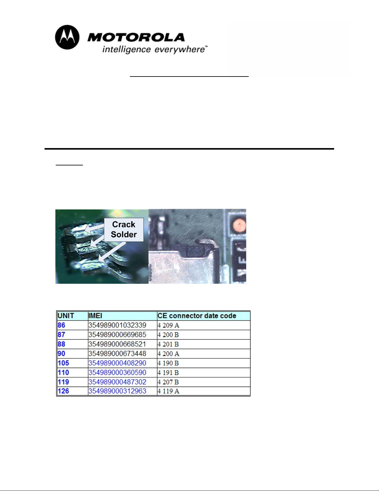
Problem
Service has detected a CE connector issue during MPX220 NPI process. Phones are
being return for “No Charge” complaints. The failure occurred in the bulk solder and cold
solder (under-reflow) was a small contributing factor but the failure appeared to be
mechanical overstress of the connector. Deformation of one of the retention tabs
indicated that a force had been applied to the front of the plastic pin assembly.
The CE connector found on the NPI failures was of Molex K08 prior to date code of
4261, which was known to have soldering issue.
MOTOROLA INTERNAL USE ONLY Page 1
Page 2
`
Consumer Solutions & Support
US Competency Center
600 North US Highway 45
Libertyville, Illinois 60048
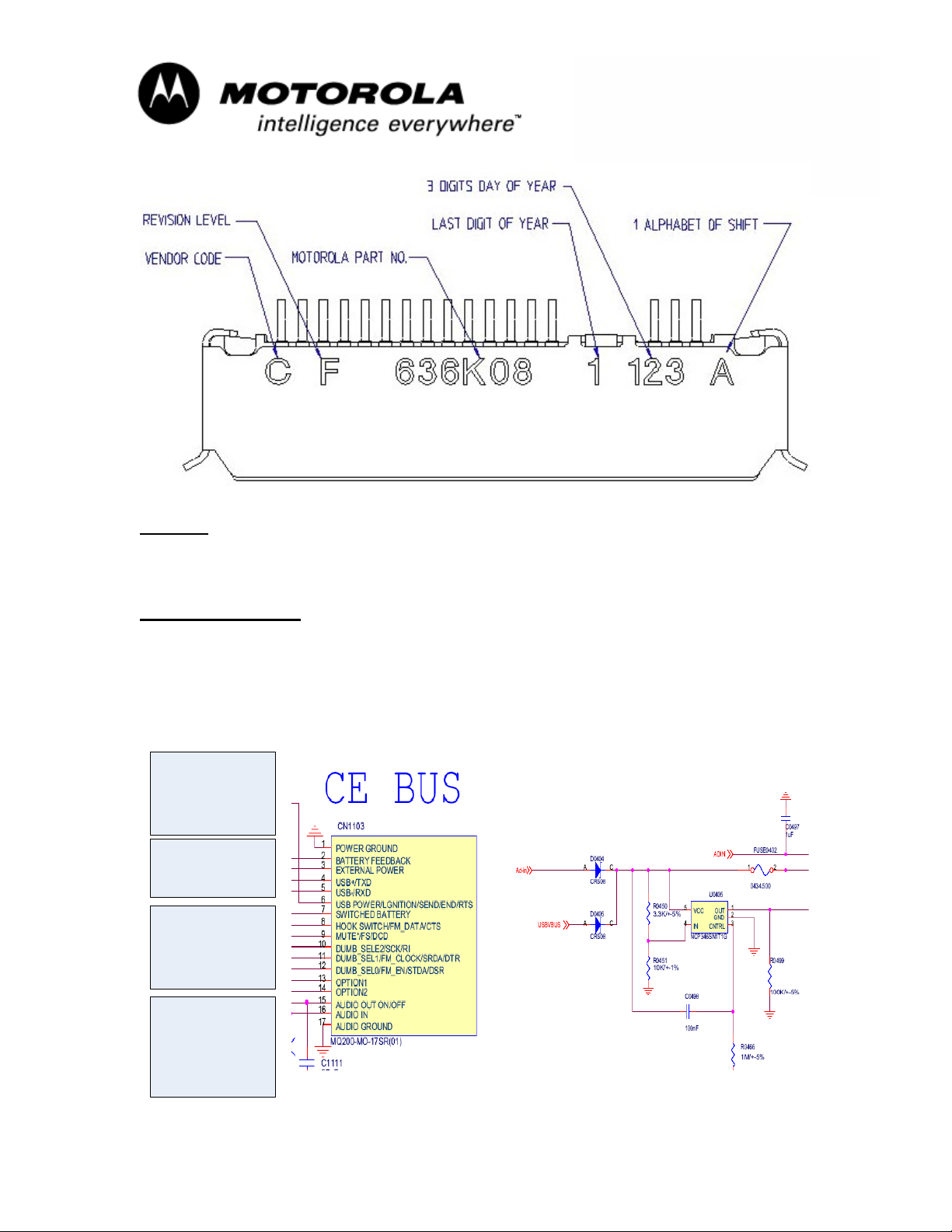
CE Connector date code configuration.
Website: gs.mot.com
Solution
ODM factory improved the reflow process to increase break point of solder and are using
K08 CE connector starting with date code 4351.
Field Service Action
Customer Returns:
When servicing any MPX220 customer phones with no charge complaints, follow
troubleshooting guide to determine is the CE connector is open:
MPX220 No Charge Troubleshooting guide
Open CE Connector
Resistance from
CE Pin 3 (+red) to
CE Pin 1 (-black)
will be open
A working unit will
measure 3 KOHM
between ground and
external power
Resistance from
CE Pin 3 (+red) to
CE Pin 6 (-black)
will be open
A working unit will
measure 9 KOHM
between USB power
and external power
since they get
combined after the
diodes.
MOTOROLA INTERNAL USE ONLY Page 2
Page 3

`
Consumer Solutions & Support
US Competency Center
600 North US Highway 45
Libertyville, Illinois 60048
Website: gs.mot.com
Confirmed failures will need to be repair by replacing the CE connector and in some case
if the connector is not damage repair by reflowing the solder.
Call Center Action:
If the customer calls with the above mentioned symptoms, please direct customer to have
their phone serviced per this FSB.
Service Inventory
N/A
Global M-Claims Codes:
Customer Complaint Codes: CHG01 (Charging - Does Not Charge)
Problem Found Code: CHG01 (Charging - Does Not Charge)
REF Designator Code: J (Connector)
Repair Code: RRT06 (Replace Part-CSB/FSB)
Or
Repair Code: RSP04 (Resolder Part-CSB/FSB)
MOTOROLA INTERNAL USE ONLY Page 3
 Loading...