


LTS 2000 Portable Radio
User’s Guide

1 LTS 2000 Portable Radio
Contents
Introduction
Basic Radio Features ......................................................................................................3
Inspection and Unpacking ..............................................................................................3
Warnings, Cautions, and Notes......................................................................................3
Getting Started
Battery Installation.........................................................................................................4
Battery Removal..............................................................................................................4
Controls, Switches, Indicators, and Connectors............................................................5
Keypad .............................................................................................................................6
Display .............................................................................................................................7
Status Indicators and LEDs ...........................................................................................7
Alert Tone Indications.....................................................................................................8
Time-Out Timer...............................................................................................................9
Conventional or Trunked Radio Operation....................................................................9
Basic Radio Operation
Radio On/Off; Power-Up................................................................................................10
Selecting a Menu Mode .................................................................................................11
Muting and Unmuting the Keypad Tones ...................................................................11
Monitor On/Off ..............................................................................................................12
Failsoft Operation (Trunked Systems Only)................................................................13
Selecting a Mode............................................................................................................14
Receiving a Call.............................................................................................................14
Transmitting .................................................................................................................15
Scan Operation
Introduction...................................................................................................................16
Turning Scan On/Off.....................................................................................................16
Deleting Nuisance Modes .............................................................................................16
Scan List Programming/Viewing..................................................................................17
Trunked Telephone Operation
General Information......................................................................................................18
Receiving a Telephone Call (Land to Mobile) ..............................................................18
Calling the Last Number Dialed ..................................................................................19
Calling a Stored Number using Direct Access.............................................................21
Storing a Number..........................................................................................................23
, Motorola, LTS 2000, SMARTNET, Private-Line, Digital Private-Line
Private Conversation, Call Alert , and SmartZone are trademarks of Motorola. Inc
1301 E. Algonquin Road, Schaumburg, IL. 60196
© 1996 by Motorola, Inc.,
Printed 6/96. All Rights Reserved.

2 LTS 2000 Portable Radio
Contents (cont.)
Trunked Private ConversationTMCall Operation
Introduction...................................................................................................................25
Answering a Private Conversation Call.......................................................................25
Calling the Last ID Number Transmitted or Received...............................................26
Direct Entry of the ID Number to be Called................................................................27
Scrolling to an ID Number in the Call List .................................................................29
Calling an ID Number at a Known Location in the Call List.....................................31
TM
Call Alert
Introduction...................................................................................................................33
Answering a Call Alert Page ........................................................................................33
Sending a Call Alert to the Last ID Number Transmitted or Received.....................34
Direct Entry of the ID Number to be Call Alert Paged...............................................35
Scrolling to an ID Number in the Call List .................................................................37
Paging an ID Number at a Known Location in the Call List .....................................38
Roaming Capability
SmartZone Operation....................................................................................................41
Locking and Unlocking a Site.......................................................................................42
Forcing a Site Change...................................................................................................42
AMSS Feature ...............................................................................................................42
Conventional Phone Operation..............................................................................43
Introduction...................................................................................................................43
Dynamic Regrouping
Introduction...................................................................................................................44
Mode Selection...............................................................................................................44
Emergency Operation
Sending an Emergency Alarm......................................................................................45
Sending a Silent Emergency Alarm .............................................................................46
Cancelling an Emergency Alarm..................................................................................46
Sending an Emergency Call..........................................................................................46
Batteries and Accessories
Battery Information ......................................................................................................47
List of Accessories .........................................................................................................50
General Information
Transmitting Distance..................................................................................................51
Radio Care .....................................................................................................................51
Safety Standards.......................................................................................................... 52
Important Safety Information ......................................................................................53
Restrictions....................................................................................................................55
Air Bag Warning Statement.........................................................................................55
Service........................................................................................................................... 58
Express Service Plus.....................................................................................................59
Parts Information..........................................................................................................60
Computer Software Copyrights....................................................................................60
Patent Disclosure ..........................................................................................................60
Page Operation

3 Introduction
p
Basic Radio Features
Welcome to the Motorola LTS 2000 portable radio.
LTS 2000 Portable radios are sophisticated, state-of-theart communication units, with 90-modes available in the
800 MHz frequency range. Pioneering the latest
technology in radio electronics, Motorola LTS 2000
Portable radio provides features that were once only
available in more expensive radios. Intelligent and
flexible software increases the radio’s capability,
decreases the radio's physical size, and permits many of
the radio's features to be customized for you.
Inspection and Unpacking
Inspect the shipping carton for any signs of damage.
Remove and check the contents to be sure that all
ordered items have been shipped. Inspect all items
thoroughly. If any items have been damaged during
transit, report the damage to the shipping company
immediately.
Radio Packing Box Contents
• Radio
• Antenna
• Nickel-Cadmium Battery
• Operating Instructions Manual
• Quick Start
Warnings, Cautions, and Notes
Throughout the text in this publication, you will
notice the use of WARNINGS, CAUTIONS, and Notes.
These notations are used to emphasize that safety
hazards exist, and care must be taken or observed.
WARNING: An operational procedure, practice,
or condition, etc., which may result in injury
or death if not carefully observed.
CAUTION: An operational procedure, practice, or
condition, etc., which may result in damage to the
equipment if not carefully observed.
Note: An operational procedure, practice, or
condition, etc., which is essential to emphasize.
4 Getting Started
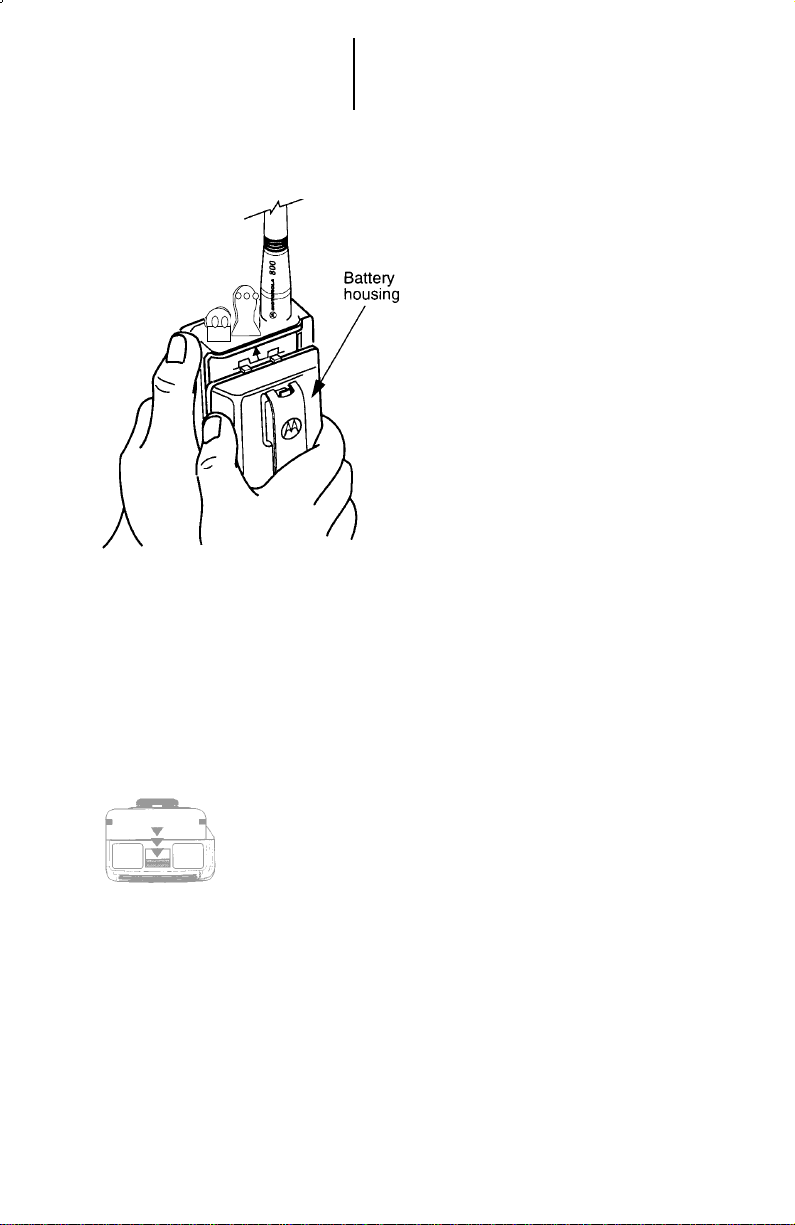
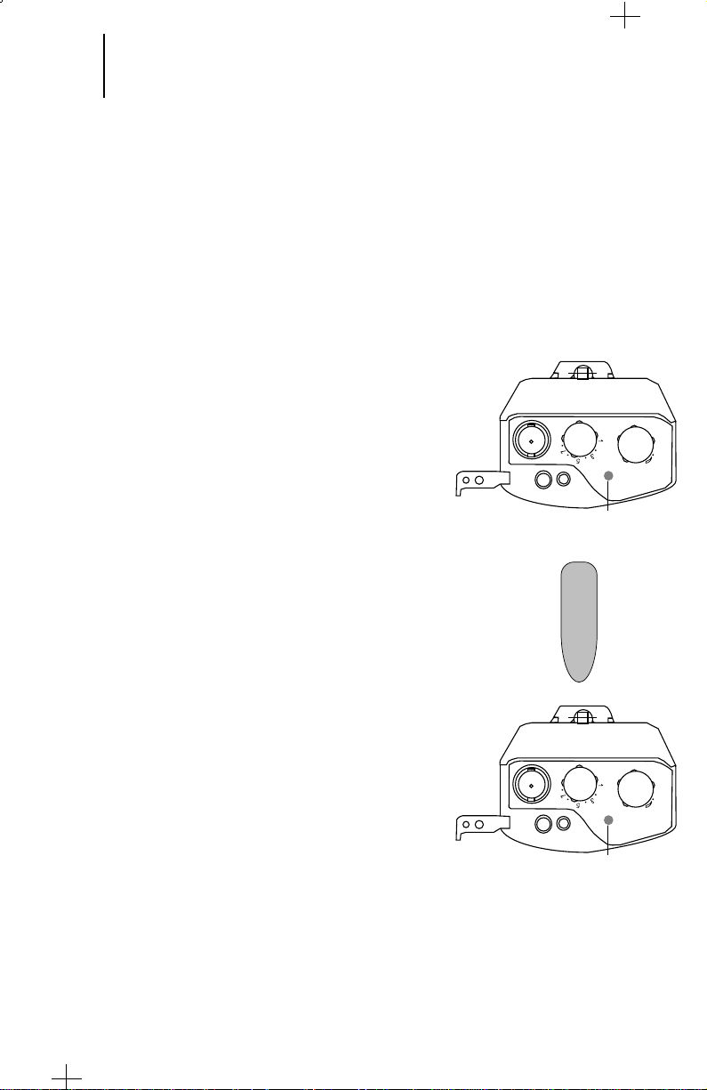
Battery Installation
1. Hold the radio with its back facing
you (knobs turned upwards).
2. Hold the battery with its name
plate facing you.
3. Insert the projected upper end of
the battery into the cut openings
located at the lower end of the
radio, and slide the battery to the
top of the radio until the battery
clicks into place.
Note:
The battery is shipped uncharged.
Batteries must be charged before
use. (See “Battery Information”
section).
Battery Removal
1. Turn off the radio and hold it so
that the battery side of the radio is
tilted down.
2. Press the battery release lever.
3. With the release lever pressed,
gently slide out the battery.
5 Getting Started
(cont.)
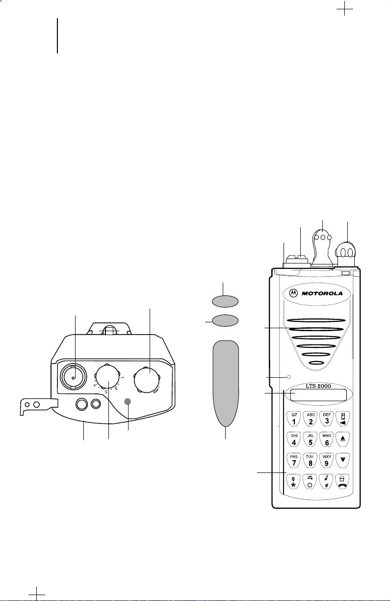
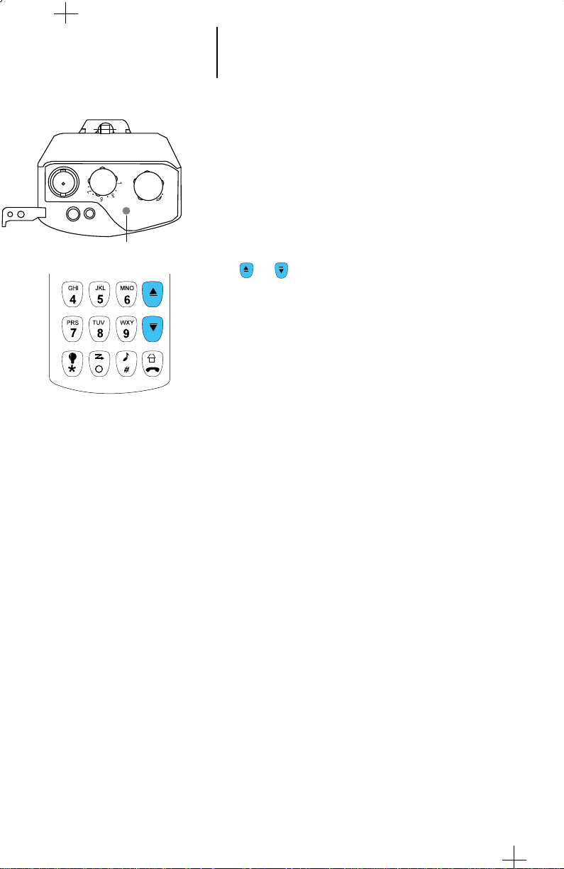
Controls, Switches, Indicators, and Connectors
1. Radio ON/OFF and V olume Contr ol Knob
2. Rotary Mode Selector Knob
3. Push-T o-Talk (PTT) Switch
4. Emergency Switch
5. Select Button
6. Accessory Connector Cover
7. Keypad
8. Display
9. Indicator LED
10. Antenna Connector
11. Microphone
12. Speaker
4
2
10
6
1
10
1
5
9
2
6
12
11
8
3
7
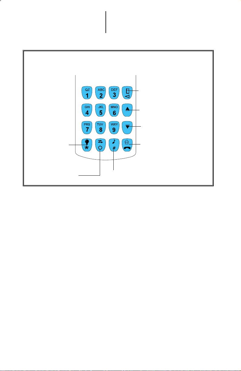
Keypad
6 Getting Started
(cont.)
Menu and Backspace Button
System Up/Scroll Up Button
System Down/Scroll Down
Backlight and
Asterisk Button
Scan and Zero Button
Home and Phone Button
Private Call (PC) and Call Alert (CA) Button

7 Getting Started
(cont.)
Display
The LTS 2000 radio has a one-line liquid-crystal display (LCD) which displays
either alphanumeric messages or feature information. Seven status annunciators
located above the character display, indicate some of the radio’s operating
conditions.
Status Indicators and LEDs
The status annunciators indicate the status of certain radio functions:
• LEDs
When RED indicates radio is transmitting
Yellow when radio is receiving
OFF when radio is not transmitting.
• Status Indicators
Battery Status ( ) – Solid when the battery is low.
Carrier Squelch ( ) – Indicates when the active conventional mode is
being monitored; ON = BEING MONITORED/
OFF = NOT BEING MONITORED.
Scan ( ) – Indicates when the radio is scanning.
Programming Mode ( ) – Indicates when the radio is in the
programming mode; ON = IN PROGRAMMING MODE/OFF = NOT IN
PROGRAMMING MODE.
Direct ( ) – Indicates whether you are talking directly to another radio
(talkaround), or through a repeater in Conventional mode; ON =
DIRECT/OFF = REPEATER.
( ) –
(LO)
Not in use.
– Not in use.
LED

8 Getting Started
(cont.)
Alert Tone Indications
The LTS 2000 radio generates a number of audible tones to indicate radio
operating conditions:
•
Low Battery – A low-battery condition is indicated by a high-pitched, cricket-
like “chirp-chirp”. There are two low battery conditions. The low battery alert
will be heard if the battery voltage falls below the low voltage level. The tone
will be emitted when the PTT is released in the transmit mode, and when the
low battery condition is detected in the receive mode.
•
Successful Power-Up – When the radio is first turned on, a short high-pitched
tone indicates that the radio has passed its power-up self test and is ready for
use.
•
Unsuccessful Power-Up – When the radio is first turned on, a short low-
pitched tone indicates that the radio has failed to pass its power-up self test and
is not ready for use. Contact your nearest Motorola Service Shop.
•
Invalid Mode – A continuous, low-pitched tone is heard when an invalid or
unprogrammed operation is performed on the radio.
•
Valid (Good) Key Press – A short, medium-pitched tone when a key is pressed
indicates that the key instruction has been accepted.
•
Invalid (Bad) Key Press – A short, low-pitched tone when a key is pressed
indicates that the key instruction has been rejected.
•
Time-Out Timer Warning – Your radio’s time-out timer limits the duration of
your transmission time. When you are pressing the PTT switch (transmitting), a
short, low-pitched warning tone will sound four seconds before the allotted time
will expire.
•
Time-Out Timer Timed-Out – If your phone conversation is longer than the
time allotted to the time-out timer, a continuous, low-pitched tone will sound,
indicating that your transmission has been cut off. This tone will continue until
you depress the PHON button.
•
Failsoft (Trunked Systems Only) – A faint “beeping” tone every ten seconds
indicates that the radio is operating in the failsoft mode.
•
Phone Busy – A “bah-bah-bah-bah” tone when telephone interconnect is
accessed, indicates that all available channels are busy and the radio is in queue
for the next available phone channel.
•
DTMF Tones (During Dialing) – When a digit (0 to 9, * and #) is dialed, a
DTMF tone will be heard.
•
Out of Range Tone – When the radio is Out of Range from the selected
Trunking site, a continues, low pitched tone is heard.

9 Getting Started
(cont.)
Alert Tone Indications (cont.)
•
Call Alert™ (Page) Received – A group of four medium-pitched tones every
five seconds indicates that your radio has received a Call Alert page.
•
Call Alert™ (Page) Sent – A single medium-pitched tone (central
acknowledge), followed by a group of four medium-pitched tones indicates that
a Call Alert page sent by your radio has been received by the target radio.
•
Private Conversation™ Call Received – A group of two medium-pitched
tones indicates that your radio has received a Private Conversation call.
•
Trunked System Busy (Trunked Systems Only) – When a trunked
system is accessed, a “bah-bah-bah-bah” tone indicates that all available
channels are busy and the radio is in queue for the next available channel.
Time-Out Timer
The time-out timer feature is programmed through the RSS. It limits the time
period of continuous transmission. If the radio is transmitting longer than the
allotted time, then :
•
A pre-alert warning tone is given ten seconds before termination of your
transmission, to warn you that your conversation is about to be cut off.
•
An alert tone is given to indicate that your transmission and system
access has been terminated.
Conventional or Trunked Radio Operation
Your LTS 2000 radio is capable of both conventional and trunked operation:
•
Conventional Operation – During conventional operation, your LTS 2000
portable radio performs like a conventional two-way radio. Therefore, you
must monitor the selected mode before transmitting by checking whether the
busy mode LED (yellow) is solid. In LTS 2000 radio, the monitor feature is
active only in the conventional mode and must be selected using the menu.
•
Trunked Operation – During trunked operation, your LTS 2000 Portable
radio offers a number of advantages, including faster system access, enhanced
privacy, and ease of operation. In a trunked system, there is no need for you to
monitor a mode before transmitting.
Note:
Home Display is a trunking or conventional mode through which all mode
dependent features can be activated.
For example, in this manual we have shown all displays with 1-A as the
trunking home mode and 01 as the conventional home mode. Any one of the
modes (trunking or conventional) can be selected as a home display by the
user.
10 Basic Radio Operation
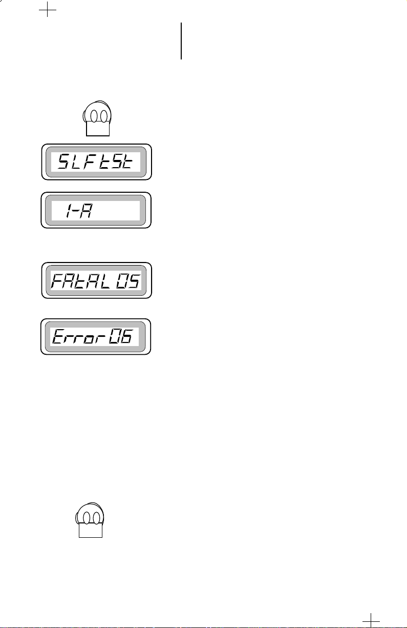
Radio On/Off; Power-Up
1. Turn the radio on by turning the Volume Control
knob clockwise. The radio goes through a powerup self test and, if it passes the check, the display
momentarily shows “SLF tSt” for about two
seconds A good-power-up, high-pitched tone
sounds to indicate that the radio has passed the
self check. The radio goes to personality # 1 and
the display shows 1-A or to that “personality”
system the radio operated before power down.
In case of test failure
or
In case of test failure after the turning the radio
ON, the display shows fatal error (Fatal 05) or
not fatal error (Error 06).
In case of self test failure, the display shows
“FAtAL 05” and the display light turns off
automatically. This is a fatal error. If “Error 06”
is displayed then the illegal continuous tone is
sounded. Turn off the radio and remove the
battery. Check the battery, reinsert it and turn
the radio on again. If the radio still does not pass
the self check, a problem exists in the radio.
Contact the nearest Motorola Service Shop.
Note:
•
The power-up self check verifies that the radio’s
microprocessor-based systems are working, but it
does not check all the RF components, nor does it
check the operation of all customer-specific
features. Motorola recommends that the
functioning of the radio be checked periodically
by an authorized Motorola service shop.
2. Turn the radio off by turning the volume knob
anti-clockwise.

11 Basic Radio Operation
(cont.)
Selecting a Menu Mode
Functions programmed into the radio can be
selected either directly through a preprogrammed
dedicated button or indirectly through the menu
button.
The following features are included in the menu
list:
• Scan List Programming/Viewing
• Force Site Search
• Site Lock/Unlock
• Phone List Programming
• ID Programming
• Keypad Tones Mute On/Off
• Monitor On/Off (Conventional Mode)
Any item, if pre-programmed, can be selected from
the menu list by pressing the menu button and
thereafter repeatedly pressing the menu button until
the required item is displayed on the list. Every time
you press the menu button takes you to the next item
on the list.
Note:
To deselect any feature, go to the menu list and
when the “off” status is displayed, press the select
button to select it
Muting/Unmuting the Keypad Tones
Press the menu button to select the menu list.
Repeatedly press the menu button until mute on
is displayed.
Press the select button located just above the PTT
switch to select mute on.
The radio automatically returns to the home
display.

12 Basic Radio Operation
(cont.)
Monitor On/Off
Note:
The monitoring feature is available when the
radio is in conventional mode and Coded
Squelch PL or DPL is preprogrammed for the
receiver frequency.
Press the menu button to select the menu list.
Repeatedly press the menu button until monitor on
is displayed.
Press the select button located just above the PTT
switch to select monitor on.
After selecting,the display automatically returns to
the home display. The speaker is enabled when the
monitor icon is displayed.
To deselect monitoring repeat the above steps.

13 Basic Radio Operation
(cont.)
Failsoft Operation (Trunked Systems
Only)
Note:
Failsoft capability can be programmed in the
codeplug.
The failsoft system ensures that you will continue to
have radio communications capability in case of trunked
system failure. During trunked operation, if the central
trunking controller fails, the radio automatically
switches to "failsoft" operation according to predefined
codeplug programming. Thus, you radio display shows
Failsoft Mode or Failsoft Personality Mode (see display).
In " failsoft" operation your radio can transmit and
receive on a conventional predetermined frequency, as
opposed to trunked mode. When you are in failsoft
operation, you hear a faint beeping sound every ten
seconds, your display shows the failsoft group and FS if
the radio has been programmed for failsoft.
Failsoft Mode
If the radio has been programmed for system
Failsoft (i.e one failsoft frequency for all talkgoups in the
system), then the display shows the system and FS.
Failsoft Personality Mode
14 Basic Radio Operation
(cont.)
Selecting a Mode
A mode is a trunking system or a conventional channel
with features slaved to it. Before you send or receive calls,
set the radio to the desired mode.
Red Tx LED
To select trunking system or conventional channels,
press the or buttons. To select trunking talkgroup use
the channel selector group located on the top panel and
rotate the knob to the desired location.
Receiving a Call
Conventional Modes
1. Turn the radio on and select the desired mode.
2. Listen until you hear activity, then adjust the volume
control for a comfortable listening level.
Note:
The squelch opening level setting may be
reprogrammed at an authorized service facility.
3. Your radio is now set to receive calls on the selected
mode.
Trunked Systems
1. Turn the radio on and select the desired mode
2. Listen until you hear activity, then adjust the volume
control for a comfortable listening level.
3. Your radio is now set to receive calls on the selected
mode.
15 Basic Radio Operation
(cont.)
Transmitting
Conventional Modes
1. Turn the radio on and select the desired mode.
2. Do not interrupt another user. If the mode on which
you are transmitting is programmed to receive PL or
DPL, ensure that the channel is not in use by
listening to activity. If the yellow LED is solid while
receiving (PTT released), this will indicate that the
channel is currently busy and you should not
transmit.
3. When the channel is available, press and hold the
PTT switch and speak slowly and clearly into the
microphone. The red Tx LED will light continuously
while the radio is transmitting. When you have
finished talking (transmitting), release the PTT to
listen (receive).
Note:
• If a mode is programmed for receive only, any
attempt to transmit on that mode will cause an
invalid-mode tone to sound until the PTT switch
is released.
Red Tx LED
Trunked Systems
1. Turn the radio on and select the desired trunked
mode.
2. Press the PTT switch. Speak slowly and clearly into
the microphone area. The red Tx LED will light
while the radio is transmitting. When your
transmission is completed, release the PTT to listen.
Notes:
• If you hear a busy tone (a low-frequency “bah-
bah-bah-bah”), release the PTT switch and wait
for a call-back tone (sounds like “di-di-dit”).
When you hear the call-back tone you will have
three seconds to press the PTT switch, allowing
you to make your call without getting another
busy signal.
• If a continuous talk-prohibit tone is heard when
the PTT switch is pressed, it means that the
radio is out of range and you will not be able to
transmit.
Red Tx LED
16
Scan Operation
Introduction
The scan feature allows you to monitor activity on
different conventional and trunked modes by scanning
a “scan list” of modes. The radio can have only one
scan list; it can contain up to eight different members
(trunk and conventional). The modes to be scanned in
a scan list can be programmed with the radio service
software (RSS). Refer to the RSS manual for detailed
information:
• Talkgroup Scan—Includes conventional modes
and trunked modes from more than one trunking
system. Priority of operation is not available in
this radio.
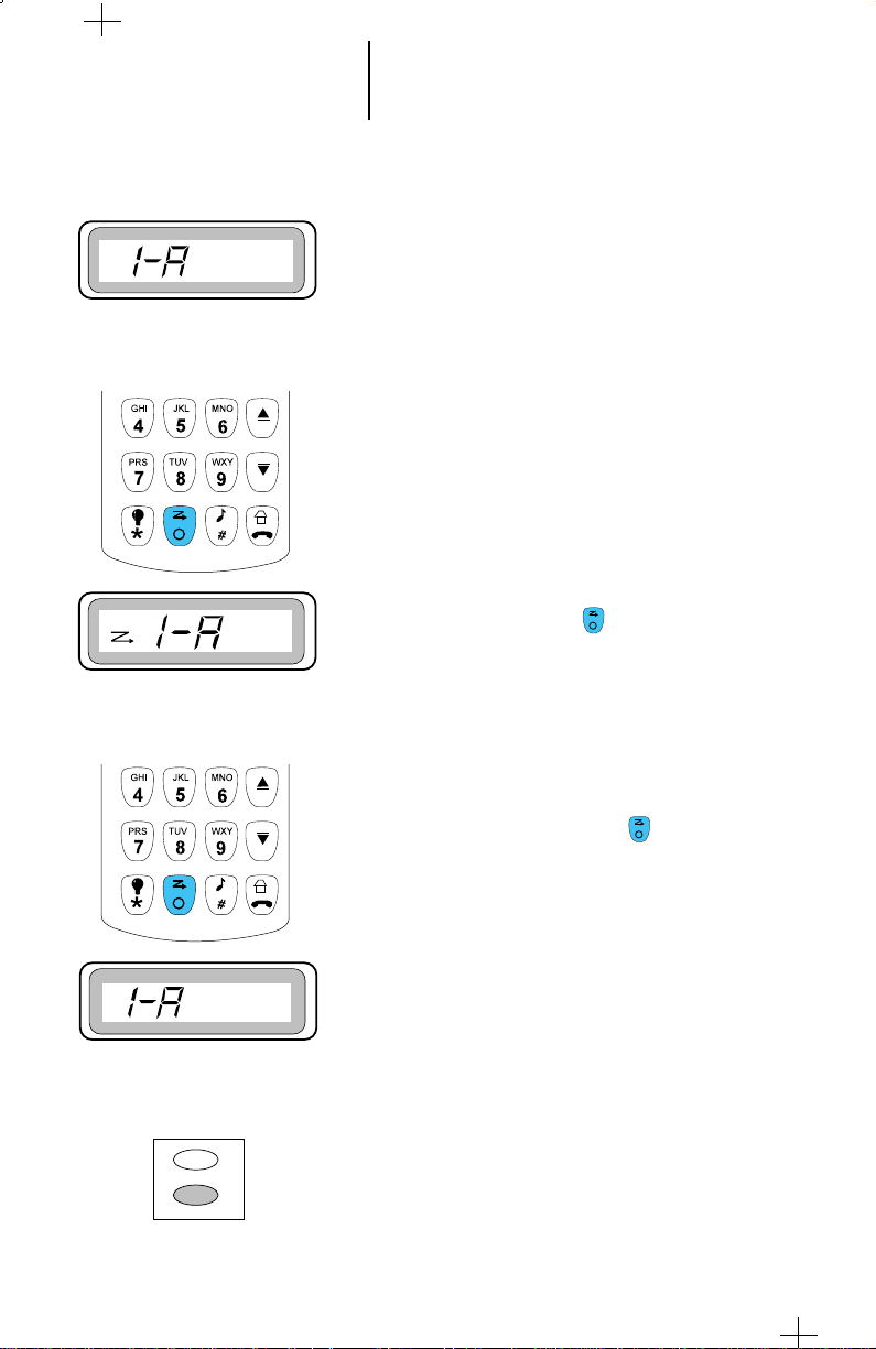
Turning Scan On/Off
1. To turn scan on, press the (Scan) button.
2. The scan status icon appears on the display,
indicating that scan is active, and the radio
begins scanning. The scan annunciator will
remain on until scan is turned off or if the radio is
turned off.
3. To turn scanning off, press the (Scan) button
once again.
4. The scan status annunciator turns off, indicating
that scan is off, and the radio stops scanning.
Note:
To initiate a call properly during scan mode,
press PTT for a few seconds.
Deleting Nuisance Modes
While scanning, if you find that a certain mode is
noisy and disturbs, you can delete it temporarily from
the scan list by pressing the select button when the
display shows the nuisance channel. As a result, the
radio excludes this mode and continues to scan the
remaining modes in the list. To include the deleted
mode back into the scan list, exit and reenter scan.
17 Scan Operation
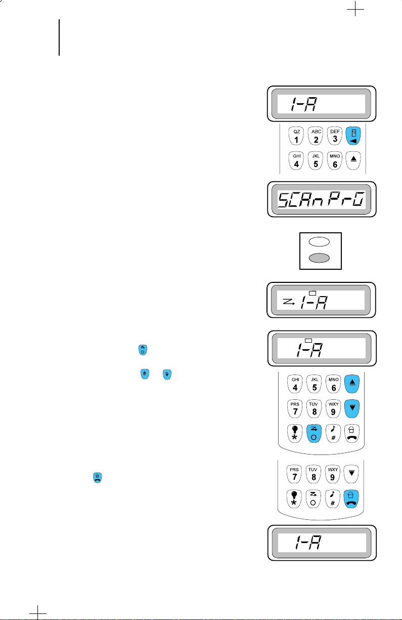
Scan List Programming/Viewing
This radio can have a preprogrammed Scan List
loaded at the factory. If you desire to make changes in the
scan list, follow the steps given below:
1. Press the menu button until “SCAn PrG” is displayed.
2. Press Select button located above the PTT switch.
3. Four beeps are sounded and display shows the default
home channel and the scan status. The scan icon
indicates that the displayed mode is in the scan list.
4. To add a member or delete a member from the list,
press the select button. To scroll through active scan
members list, press (Scan) button; but to scroll
through all modes in the radio (trunk and
conventional) use the or buttons.
If you want to add a member to the list, and the list is
full, then the radio indicates with a medium beep.
5. When you have finished scan programming/viewing,
press the (Home) button to exit.

18 Trunked Telephone Operation
General Information
The trunked telephone feature is similar to that of a
standard telephone.
Receiving a Telephone Call - land to Mobile
1. When you receive a telephone call, you hear the
telephone ring and the characters PH will be
displayed with the talkgroup.
2. Press the Phone button to answer the call. The
display shows “PHonE”. Press the PTT switch while
talking and release while listening.
Note:
Incoming phone-call numbers are not stored in
the phone list.
3. If during the conversation you need DTMF overdial,
use the keypad. If you use scroll or button to
scroll through the list then press PTT switch to
send the numbers.
4. Carry on with your conversation in the usual way.
5 When you have finished your conversation, press
the (Home) button to hang-up.
6. The radio will return to the Home display.

19
Trunked Telephone Operation
(cont.)
Calling the Last Number Dialed
1. Press the (Phone) button to make a phone call.
2. ACCESS will be displayed momentarily and then
the last dialed phone number.
Notes:
• If you are out of the trunked system range or the
phone interconnect is out of service, “no
PHonE” is displayed for six seconds after trying
to access the system, and a continuous lowpitched tone is emitted.
• If the trunked phone interconnect is in use, a
busy tone sounds and “PH buSY” is displayed.
If you hang up, you will lose your place in the
queue.
• This is a timed message. If you cannot access the
telephone system (no dial tone heard), you need
to press the
start again from step 1 of this procedure.
3. To redial the last number which was dialed, press the
PTT switch.
(Home) button
to hang up, and

20
Trunked Telephone Operation
(cont.)
Calling the Last Number Dialed
4. If the system access is successful, you will hear a
dial tone and the last number dialed will be
displayed.
5. The telephone number will be sent out by pressing
the PTT switch, and you will hear tones as they
are being sent. After the complete number has
been dialed, you will hear either a busy tone or
ring tone. If you hear a busy tone, follow step 6
given below.
6. When you have finished your conversation, or if
the number you are calling is busy or there is no
answer, press the (Home) button to hang-up.
(cont.)
7. The radio will return to the home display.

21
Trunked Telephone Operation
(cont.)
Calling a Stored Number using Direct
Access
1. To make a phone call, press the (Phone)
button.
2. Access will be displayed momentarily and then the
last dialed phone number.
Notes:
• If you are out of the trunked system range or the
phone interconnect is out of service, “no PHonE” is
displayed for six seconds after trying to access the
system, and a continuous low-pitched tone is
emitted.
• If the trunked phone interconnect is in use, a busy
tone sounds and “PH buSY” is displayed. If you
hang up, you will lose your place in the queue.
• This is a timed message. If you cannot access the
telephone system (no dial tone heard), you need to
press the to hang up, and start again from
step 1 of this procedure.
Note:
• The display is able to accommodate eight digits. If
the last dialed number is more than eight digits
then the first eight and the digits after the eight
digit are displayed alternately.

22
Trunked Telephone Operation
Calling a Stored Number using Direct
Access (cont.)
3. To scroll through the phone list, use the scroll or
scroll buttons.
Upon entering the scroll option, use the direct entry
which will take you to the direct location on the list.
4. When you have selected the member you wish to call,
press the PTT switch.
5. When you have finished your conversation, or if the
number you are calling is busy or there is no answer,
press the (Home) button to hang-up.
6. The radio will return to the home display.

23 Trunked Telephone Operation
(cont.)
Storing A Number
1. To store a telephone number, press (Menu)
button, till “PHon PrG” appears on the display.
2. Press the Select button.
3. “PH LoC 1” will be displayed momentarily, and then
the phone number to indicate the first stored
number is selected.
4. Use the scroll up and scroll down buttons to
scroll through the list or directly press your allotted
digit (0 through 9 ) for your required location
number.
5. After you have reached the memory location where
you would like to store the number, press the
SELECT button.
Note:
The factory default number or last stored number
will be displayed

24 Trunked Telephone Operation
(cont.)
Storing A Number (cont.)
6. The new telephone number can now be entered
from the keypad, using any of the numeric (0 – 9)
keys, as well as the “*” and “#” button. You can
also enter a pause in the telephone number by
using the button bearing the asterisk sign and
then the button bearing the pound sign.
7. The display changes to show the numbers as they
are being entered. 16 digits can be entered but
only 8 can be displayed.
Note:
•
Once you have started entering numbers, the
(Menu) button will function as a delete
key.
•
When the last digit on the display has been
erased, an additional press of this key will
cause “ _ _ _” to appear on the display.
8. After dialing the desired number, press the select
button to store the new number. The display will
first show the location number momentarily, and
then the new stored number.
Note:
At this point another location/s can be changed by
repeating the steps 4 through 8.
9. When you have finished your conversation, or if
the number you are calling is busy or there is no
answer, press the (Home) button to hang-up.
25 Trunked Private Conversation™
Call Operation
Introduction
The Private Conversation feature allows you to carry
on a conversation that is heard only by two parties. In
this feature, if you want to view the calling radio’s ID
number before answering, press the (Call) button.
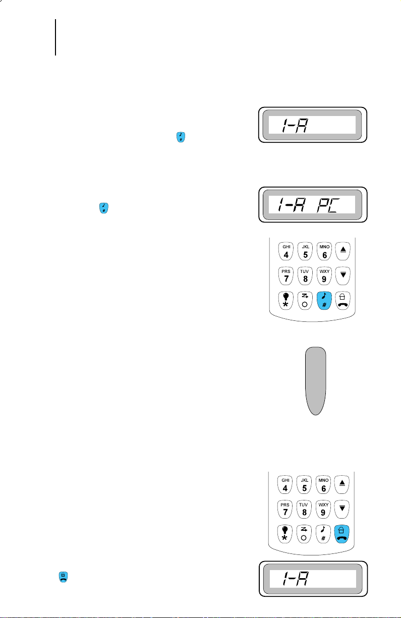
Answering a Private Conversation Call
1. When your radio receives a Private Conversation
call, you will hear two alert tones, the display will
show “1-A PC” and you will hear the caller.
2. Press the (Call) button. The display will show
PC momentarily and then the incoming caller’s ID
number.
CAUTION: If you press the PTT button before
you press the CALL button, the response will
be transmitted to everyone in the talkgroup
(see dispatch mode operation).
Note:
When in home display mode, if the PTT is pressed
before the repeater hang-up time, then the call
remains a private call.
3. Press the PTT switch to carry on a Private
Conversation with the caller. The caller’s ID number
will remain on the display for the duration of the
call.
Notes:
•
If there is a delay in answering your incoming call
and the system happens to be busy, then a busy tone
will be heard. When a channel becomes available,
you will receive a call back tone, and your radio
automatically keys up for three seconds so that you
can start your conversation. Press PTT to talk.
•
When the radio is Out of Range from the selected
Trunking site, a continuous low pitched tone is heard.
4. When you have finished your conversation, press the
(Home) button to return to the home display.
26 Trunked Private Conversation™
Call Operation
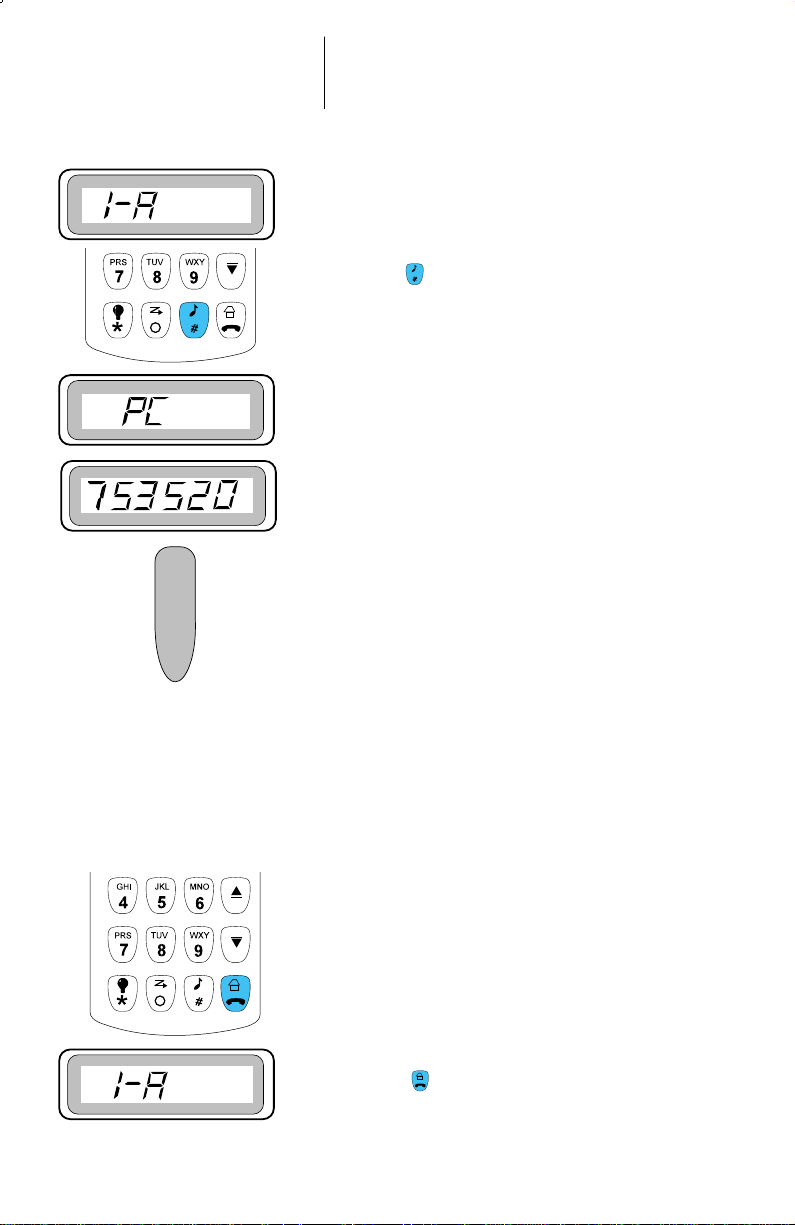
Calling the Last ID Number
Transmitted or Received
1. To call the last ID number transmitted or received,
press the (Call) button.
2. The display shows PC momentarily and then the last
called ID.
3. Press and hold the PTT switch to carry on a Private
Conversation.
Notes:
•
If there is a delay in answering your incoming
call and the system happens to be busy, then a
busy tone will be heard. When a channel
becomes available, you will receive a call back
tone, and your radio automatically keys up for
three seconds so that you can start your
conversation. Press PTT to talk.
•
When the radio is Out of Range from the selected
Trunking site, a continuous low pitched tone is
heard.
(cont.)
4. Pause for a second to allow the alert tone to sound in
the receiving radio, then begin talking. Speak slowly
and clearly into the microphone.
5. If the party you are calling does not respond, then
press the (Home) button to exit the Private
Conversation feature and return to the home display.

27 Trunked Private Conversation™
Call Operation
Direct Entry of the ID Number to be
Called
1. Press the (Call) button to call the ID number
directly.
2. The display shows “PC” momentarily and then
changes to show the last ID number transmitted or
received or blank display with six dashes if last ID
was stored. You can now enter the ID number to be
called.
3. Enter the new six-digit ID number using the
keypad.
(cont.)
4. On the display, the old ID number disappears. The
new digits appear as they are being entered. The
cursor shifts to the right to indicate the location of
the next number to be entered.
Note:
• If you press PTT after entering an illegal ID
number is entered, then illegal tone is heard
and the display shows “iLLEG Id” . A few
moments after the PTT is released, the illegal
number you have entered will be displayed.
• Use (Backspace) button to delete the
displayed digits. Use the keypad to enter the
desired number.
28 Trunked Private Conversation™
Call Operation
Direct Entry of the ID Number to be
Called (cont.)
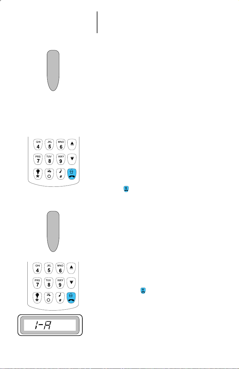
5. Press the PTT switch. Wait for a second to allow the
alert tone to sound in the receiving radio, then begin
talking.
Notes:
•
If there is a delay in answering your incoming call
and the system happens to be busy, then a busy tone
will be heard. When a channel becomes available,
you will receive a call back tone, and your radio
automatically keys up for three seconds so that you
can start your conversation. Press PTT to talk.
•
When the radio is Out of Range from the selected
Trunking site, a continuous low pitched tone is heard.
6a. If the party you are calling does not respond, then
press the (Home) button to exit the Private
Conversation feature.
or
(cont.)
6b. If the party you are calling does answer the call, you
will hear his/her voice.
7. Press the PTT switch to carry on a Private
Conversation with the called party.
8. When you have finished your conversation, or if the
radio you are calling does not answer or is not in
service, press the (Home) button; the radio will
return to the home display.
29 Trunked Private Conversation™
Call Operation
Scrolling to an ID Number in the Call List
1. To scroll to a certain ID number on the
preprogrammed call list, press the (Call) button to
initiate the Private Call feature.
Note:
Each trunking system has its unique PC/Call Alert
list. The same list is shared by both Private
Conversation and Call Alert features.
2. The display shows PC momentarily and then changes
to show the last ID number that was transmitted or
received, or blank display with six dashes if the last ID
was not stored. You can now enter the ID number to be
called.
(cont.)
3. To scroll through the call list, use the scroll or scroll
button.
4. When scrolling through the list, first “ID LOC” is
displayed momentarily with the location number, and
then the ID number.
Note:
The last location in the list bears the radio ID number.
30 Trunked Private Conversation™
Call Operation
5. Press the PTT switch. Wait for a second to allow the
alert tone to sound in the receiving radio, then begin
talking.
Notes:
•
If there is a delay in answering your incoming call
and the system happens to be busy, then a busy tone
will be heard. When a channel becomes available,
you will receive a call back tone, and your radio
automatically keys up for three seconds so that you
can start your conversation. Press the PTT switch to
talk.
•
When the radio is Out of Range from the selected
Trunking site, a continuous low pitched tone is heard.
6a. If the party you are calling does not respond, then
press the (Home) button to exit the Private
Conversation feature.
or
(cont.)
6b. If the party you are calling does answer the call, you
will hear his/her voice.
7. Press the PTT switch to carry on a Private
Conversation with the called party.
8. Press the (Home) button after completing your
call; the radio will return to the home display.

31 Trunked Private Conversation™
Call Operation
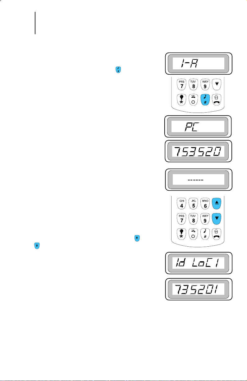
Calling an ID Number at a Known
Location in the Call List
1. You can also call an ID number at a particular
location in the preprogrammed call list. To scroll to a
certain ID number on the preprogrammed call list,
press (Call) button to initiate the Private Call
feature.
2. The display shows PC momentarily and then changes
to show the last ID number that was transmitted or
received, or blank display with six dashes if the last
ID was not stored. You can now enter the ID number
to be called.
(cont.)
3. To reach the required known location, enter the list,
and press scroll or scroll button. The
Scroll button will take you forward to the first or next
member on the list; the scroll button will take you
backward to the last or previous member on the list.
Note:
When scrolling through the list, first “Id LoC” is
displayed momentarily with the location number, and
then the ID number.
4. When “Id LoC” is displayed, use keypad digits 1
through 8 for the stored ID members location. Digit 9
displays the owner’s ID and 0 the last ID.

32 Trunked Private Conversation™
Call Operation
Calling an ID Number at a Known
Location in the Call List (Cont)
5. Press the PTT switch. Wait for a second to allow the
alert tone to sound in the receiving radio, then begin
talking.
Notes:
•
If there is a delay in answering your incoming call
and the system happens to be busy, then a busy tone
will be heard. When a channel becomes available, you
will receive a call back tone, and your radio
automatically keys up for three seconds so that you
can start your conversation. Press PTT to talk.
•
When the radio is Out of Range from the selected
Trunking site, a continuous low pitched tone is heard.
6a. If the party you are calling does not respond, then
press the (Home) button to exit the Private
Conversation feature.
or
(cont.)
6b. If the party you are calling does answer the call, you
will hear his/her voice.
7. Press the PTT switch to carry on a Private
Conversation with the called party.
8. Press the (Home) button after completing your
call; the radio will return to the home display.

33
Call Alert™ Page Operation
Introduction
The Call Alert page feature enables your radio to
function like a pager (beeper). Your radio (as
programmed by the RSS) can receive and respond to
pages from other radios, and send pages to them.
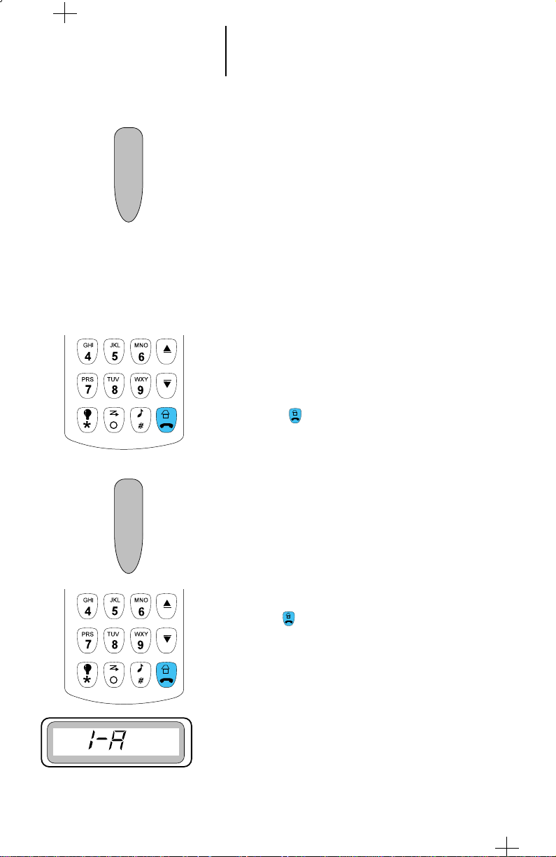
Answering a Call Alert Page
1. When a Call Alert page is being received, you will
hear a recurring four-beep tone until you answer the
call or reset the radio. The display will show 1-A CA.
Note:
Any button press, keypad press, or mode change will
turn off the Call Alert audible and visual indicators.
2. To answer the page, press the PTT switch or any
button from the keypad. The display will show the
current talkgroup and the audible alert will turn off.
The ID number of the radio that paged you is stored
as “the last ID number received.”

34
Call Alert™ Page Operation
(cont.)
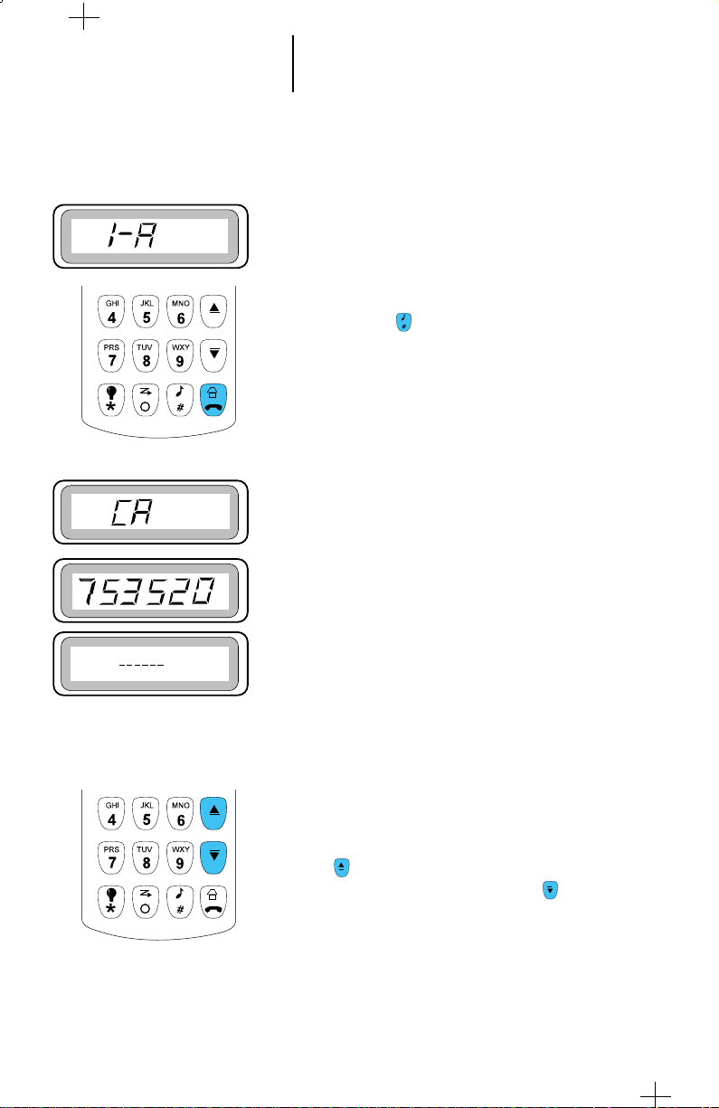
Sending a Call Alert to the Last ID
Number Transmitted or Received
1. To send a Call Alert to the last ID number
transmitted or received, press the (Call) button.
Note:
• If the radio is programmed with both Private
Call (PC) or Call Alert (CA) features, then press
the call button twice to enter the CA mode.
2. The display shows CA momentarily and then the
last ID number.
3. Press the PTT switch to send the ID number.
3a. If you hear one beep, it indicates that the ID number
has been received by the system, the radio you are
paging is not on the air, and your radio remains in
the Call Alert mode. You can either go back to step 3
and press the PTT switch to send the ID number
again, or press the (Home) button to return to
the home display.
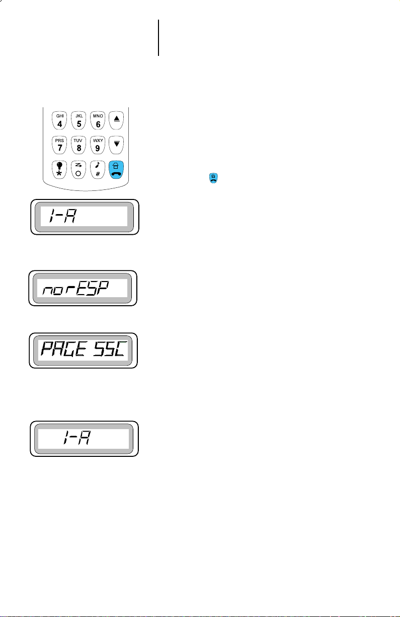
Note:
If after six seconds the called radio fails to
acknowledge the alert, a low-pitch alert tone sounds
and the display changes to “no rESP”. You may try
this sequence again.
or
3b. If you hear five beeps, it indicates that the ID
number has been received by the system, the radio
you are paging is on the air and has received your
page. The display shows “PAGE SCC” momentarily
and the radio automatically returns to the home
display.

35
Call Alert™ Page Operation
(cont.)
Direct Entry of the ID Number to be
Call Alert Paged
1. Press the (Call) button to directly enter the ID
number to be called.
Note:
• If the radio is programmed with both Private
Call (PC) or Call Alert (CA) features, then press
the call button twice to enter the CA mode.
2. The display shows CA momentarily and then the last
ID number transmitted or received, or blank display
with six dashes if the last display was not stored. You
can now enter the ID number to be paged.
3. Enter the new six-digit ID number from the keypad.
On the display, the old ID number disappears, and
the new digits appear as they are being entered. The
cursor flashes to indicate the location of the next
number to be entered.
Notes:
• If less than six digits are entered and the PTT
switch is pressed, you will hear a bad-key press
tone and the display will show “iLLEG Id” . A
few moments after the PTT is released, the
illegal number you have entered will be
displayed.
• Once you have started entering numbers, the
(Backspace Delete) button will function
as a backspace key. Pressing this key will cause
the last digit entered to be erased, and the
cursor to move to the left. When the last digit
has been erased, an additional press of this key
will cause last member of the preprogrammed
Private Conversation list to be displayed.

36
Call Alert™ Page Operation
(cont.)
4. Press the PTT switch. Wait for a second to allow the
alert tone to sound in the receiving radio, then begin
talking.
5a. If you hear one beep, it indicates that the ID number
has been received by the system, the radio you are
paging is not on the air, and your radio remains in the
Call Alert mode. You can either go back to step 3 and
press the PTT switch to send the ID number again, or
press the (Home) button to return to the home
display.
or
5b. If you hear five beeps, it indicates that the ID number
has been received by the system, the radio you are
paging is on the air and has received your page. The
display shows “PAGE SCC” momentarily and the
radio automatically returns to the home display.

37
Call Alert™ Page Operation
(cont.)
Scrolling to an ID Number in the Call List
1. To scroll to an ID number to be Call Alert paged from
the preprogrammed call list, press the (Call)
button.
Note:
• If the radio is programmed with both Private
Call (PC) or Call Alert (CA) features, then press
the call button twice to enter the CA mode.
2. The display shows CA momentarily and then the last
ID number transmitted or received, or blank display
with six dashes if the last display was not stored. You
can now scroll to the ID number in the call list.
3. To enter the list, press scroll or scroll button.
The scroll button will take you forward to the
first or next member on the list; the scroll button
will take you backward to the last or previous
member on the list.
4. When scrolling through the list, first “Id LoC” is
displayed momentarily with the location number, and
then the ID number.
Note:
• The last number in the list is the radio ID
number.
5. To exit press the (Home) button
38
Call Alert™ Page Operation
(cont.)
Paging an ID Number at a known Location in
the Call List
1. You can also Call Alert page an ID number at a
particular location in the preprogrammed call list .
2. To page an ID number from the preprogrammed call
list, press the (Call) button.
Note:
• If the radio is programmed with both Private
Call (PC) or Call Alert (CA) features, then
press the call button twice to enter the CA
mode.
3. The display shows CA momentarily and then the
last ID number transmitted or received, or blank
display with six dashes if the last display was not
stored. You can now scroll to the ID number in the
call list.
4. The scroll button will take you forward to the
first or next member of the list; the scroll button
will take you backward to the last or previous
member of the list.

39
Call Alert™ Page Operation
(cont.)
Paging an ID Number at a known Location
in the Call List (Cont)
5. When scrolling through the list, first “Id LoC” is
displayed momentarily with the location number, and
then the ID number.
Note:
The last number in the list is the radio ID number.
6. When you have selected the member you wish to call,
press the PTT switch. The display freezes to show the
selected member’s ID number which is to be
transmitted.
or
7. Press the (Home) button to exit.
40
Call Alert™ Page Operation
(cont.)
8a. If you hear one beep, it indicates that the ID number
has been received by the system, the radio you are
paging is not on the air, and your radio remains in
the Call Alert mode. You can either go back to step 3
and press PTT switch to send the ID number again,
or press the (Home) button to return to the home
display.
Note:
If after six seconds the called radio fails to
acknowledge the alert, a low-pitch alert tone sounds
and the display changes to “no rESP” You may try
this sequence again.
or
8b. If you hear five beeps, it indicates that the ID number
has been received by the system, the radio you are
paging is on the air and has received your page. The
display shows “PAGE SCC” momentarily and the
radio automatically returns to the home display.

41
Roaming Capability
SmartZoneTMOperation
Radios that operate in a SmartZone system will enjoy
the benefits that SmartZone offers over AMSS operation.
SmartZone is a wide-area coverage system that will allow
up to 50 sites to be operational in the system. SmartZone
brings several enhancements over AMSS operation such
as:
• Dynamic Site Assignment - Allows the zone
controller to dynamically assign channels at sites
where required, as opposed to bringing up channels at
all sites as AMSS systems do.
• Variable Density - Allows sites to have varying
numbers of channel resources to accommodate lowdensity areas as well as high density areas.
• Automatic Site Registration/Deregistration -
Smartzone radios automatically send in their unit IDs
and current mode selections upon power up, power
down, site switches, talkgroup changes, and when
they exit emergency operation. This allows the zone
controller to know where the radio is at all times, and
also what talkgroup the radio has selected.
• Enhanced FailSoft Operation - If a site
experiences a complete failure, it will revert to failsoft
operation like today’s SMARTNET system. A
SmartZone radio, however, can be programmed in the
list of control modes. The radio will periodically scan
the control mode to check for the presence of a valid
control mode (in case the radio roamed into a site
which is trunking.
• Locking and Unlocking a Site - As in AMSS, you
can force the radio to stay locked onto a site. Yet you
can still force the radio to scan to another site while
the site is locked. The radio will automatically become
site locked to the next site it finds.
• Site Switching in SmartZone- When the radio
(unlocked state) is out of range, it will automatically
scan for a new site from a list of 32 channels.
42
Roaming Capability
(cont.)
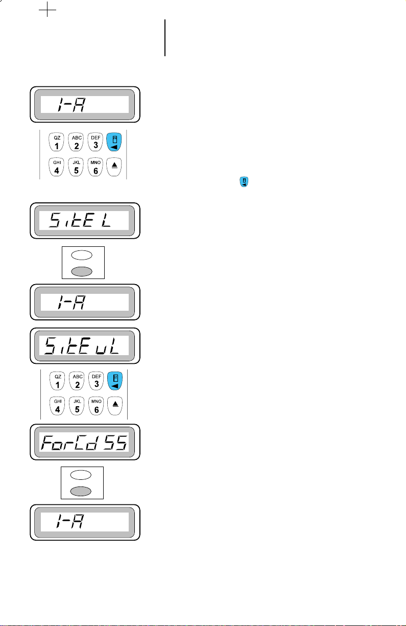
Locking and Unlocking a Site
1. If the radio is programmed to include SmartZone or
AMSS, it requires to designate the site from which it
should start operating on the system. To do so, choose
the proper mode from the mode list.
2. To verify whether the radio is presently locked onto
the site, press the (Menu) button. “SitE L” or
“Site u/L” is displayed.
3. If you wish to lock on a specific site, verify “SitE L”
appears on the display.
4. Press the Select button. The display automatically
reverts to the home display.
5. If you wish to unlock a specific site, verify that " SitE
u/L" appear on the display. To change the selection,
press the Select button. As a result, the radio will
unlock the required site.
Forcing a Site Change
1. Repeatedly press the menu button until “ForCd SS “
is displayed.
2. Press the select button.
3. The radio starts searching for a new site and the
display reverts to the home display.
AMSS Feature
AMSS feature is available either in the automatic
(unlocked) or manual (locked) mode. In the automatic
mode, the radio switches as one goes out of range and the
other comes within range. In the manual mode, the site
used is the site that is selected when you have entered the
manual mode. A forced site search (FCC) can be initiated
either in the automatic or manual mode.

43
Conventional Phone Operation
Introduction
The conventional telephone feature allows you to use
your conventional radio similar to a standard telephone.
• To make a call, press the (Phone) button. The
display will show PH with the current conventional
system.
• In this mode, for every number entered from the
keypad including * and # buttons, the corresponding
DTMF tone will be sent.
• Type the relevant access code to enter the telephone
system. If the access is successful, you will hear dial
tone.
• Dial the required telephone number. Each digit is
sent on each key press.
• If the calling party answers, carry on with the
conversation in the usual way. Press the PTT to talk
and release the PTT to listen.
• When you have completed your conversation, or if the
number you have dialed is busy, or does not answer,
press the (Home) button to hang up.

44
Dynamic Regrouping
Introduction
The dynamic regrouping feature allows the
dispatcher to temporarily reassign selected radios,
operating in the same or different trunked modes, to a
single special mode so that they can communicate with
each other. When your radio has been dynamically
regrouped you will hear a distinct “gurgle” tone.
Mode Selection
You will not notice this feature until a dynamic
regrouping feature is sent by the dispatcher. If you switch
to the dynamic regrouping position without being
dynamically regrouped, then you will hear an invalid
mode tone. The dynamic regrouping feature allows the
dispatcher to temporarily reassign selected radios,
operating in the same or different trunked modes, to a
1. When your radio has been dynamically regrouped,
you will hear a “gurgle” tone. Your radio will be
automatically switched to the dynamic regrouping
mode.
2. Use the scroll or scroll buttons to reach the
dynamic regrouping position for transmitting on the
dynamic regrouping mode.
Note:
Until you select the correct position, you will hear a
gurgle tone each time you press the PTT switch
indicating that you are transmitting on a dynamic
regrouping mode and not the mode indicated by the
position of the mode selector knob.
3. Talk and listen as usual.
4. When the dynamic regrouping is cancelled by the
dispatcher:
- If the mode selector knob is in the dynamic
position, an invalid mode tone will be heard until a
normal mode is selected.
- If the mode selector is in any other position, then
the radio will transmit in the selected mode.
5. The dispatcher may classify regrouped radios into
either select enabled or select disabled category:
- Select enabled radios are free to make mode
changes to any available mode including dynamic
regrouping mode.
- Select disabled mode radios cannot change modes,
since the dispatcher has specifically chosen to
remain in the dynamic mode.

45 Emergency Operation
Emergency Operation
The emergency operation switch is located on the left
side of the radio set. When this switch is pressed, an
emergency signal is sent. This signal has precedence
over all other signals. The emergency signal can be sent
as emergency alarm or emergency call. The LTS 2000
radio can be equipped with either or both features.
• In the emergency alarm feature, data is transmitted
in the trunked control mode. This alerts the
dispatcher, indicates the emergency condition, and
identifies the unit sending the emergency signal.
• The emergency call feature is a type of dispatch
operation which gives your radio priority access to the
system. The Emergency call feature is programmable
via the radio service software (RSS) for either tactical
or non-tactical operation. Tactical emergency
operation places the call in the currently selected
mode; non-tactical operation places the call in a
predetermined emergency mode.
“Emergency” signals a critical situation. It
should never be used for any other reason.
Sending an Emergency Alarm
1. Press and hold the emergency switch until a short,
medium-pitched emergency tone is heard.
Consequently, the following sequences occur:
a. The display shows “1-A EA”.
b. When the trunked emergency alarm is
acknowledged by the central controller, the radio
sounds four beeps and the display returns to the
home display.
2. If the radio is equipped with the Emergency Alarm
feature, the radio returns to normal operation.

46 Emergency Operation
(cont.)
Sending a Silent Emergency Alarm
In radios with silent emergency alarm option, when
the emergency button is pressed, an emergency signal is
sent to the dispatcher. During the emergency alarm
procedure: the light will not light, tones will not be heard,
and the display will not change. enables remains the same
and the beeps are not heard. The audio will be muted
(turned off) and will remain so until you exit the
emergency state.
Cancelling an Emergency Alarm
Press the emergency button for more than one
second; a medium-pitched emergency-exit tone sounds
until the button is released and the radio returns to
normal operation.
The alarm can also be cancelled (without emergencyexit tone) by:
• pressing the PTT switch (see the note below),
• turning the radio off, or
• receiving an acknowledgement from the
dispatcher.
Note:
Pressing the PTT switch while the radio is in
emergency alarm operation, will place the radio
in emergency call operation .
Sending an Emergency Call (On Trunking Mode
Only)
1. Press the emergency button. The Red LED lights and
a short, medium-pitched emergency tone sounds.
2. Press the PTT switch to request a priority mode
assignment in the trunk system.
3. While the radio is in emergency call operation it
operates in the usual dispatch manner.
4. It is important that you exit the emergency call mode
when you have finished your emergency call. To do
this, again give a long press on the emergency button.
You will hear a medium-pitched emergency exit tone
and the radio will return to normal operation.

47 Batteries and Accessories
Battery Information
The LTS 2000 radio receives its power (7.5Vdc) from a
rechargeable nickel-cadmium battery. This battery is a
safe, dependable power source for your radio. Proper care
of the battery will ensure its effectiveness and allow for
peak radio performance.
Recharging Nickel-Cadmium Batteries
Recharge the battery before use to ensure optimum
capacity and performance. The battery is designed
specifically to be used with a Motorola charger. Charging
with a non-Motorola equipment may lead to battery
damage and void the battery warranty.
Note: When charging the battery attached to the
radio, turn the radio off to ensure a full charge.
WARNING: Do not attempt to change or charge
the battery in a hazardous atmosphere.
Charging Temperature
The battery should be at about 77°F (room
temperature) whenever possible. Charging a cold battery
(below 50° F) may result in leakage of electrolyte, and
ultimately, in failure of the battery. Charging a hot battery
(above 95°F) results in reduced discharge capacity,
affecting the performance of the radio.
Short Circuit
Care should be taken to avoid external short
circuiting of the battery.
WARNING: A sustained high-rate discharge (for
example, a paper clip placed accidentally across
the battery contacts) may permanently damage
the battery, void the battery warranty, and
create a burn or fire hazard.
Memory Effect (Reduced Charge Capacity)
Memory effect is a phenomenon caused by temporary
loss in battery capacity or voltage due to repetitive shallow
discharging or long-term overcharging. This memory effect
has been virtually eliminated from Motorola batteries by
the use of new cell technology.

48 Batteries and Accessories
(cont.)
Rechargeable Battery Care
These battery tips will help assure you the highest
performance and longest cycle life from your Motorola
rechargeable battery.
• Charge your new battery overnight (14-16 hours)
before using it. This is referred to as "initializing"
and will enable you to obtain maximum battery
capacity.
• New batteries can be stored up to two years without
significant cycle loss.
• Store new/unused batteries at room temperature in
a cool dry area.
• Batteries which have been in storage should be
charged overnight.
• When using a Motorola rapid charger, leave battery
in charger for an additional 1-2 hours after the green
light appears.
• Do Not leave your radio & battery in the charger
when not charging. Continuous charging will
shorten battery life. (Don't use your charger as a
radio stand).
• Only charge batteries when they need it. If it isn't
fully discharged, don't recharge it. (We recommend
you purchase a second battery for multiple/longer
duty cycle applications).
• Do not return fully charged batteries to the charger
for an "extra boost". This action will significantly
reduce cycle life.
• Stabilize battery to room temperature (72 degrees
Fahrenheit) before charging. Charging below 40
degrees Fahrenheit and above 104 degrees
Fahrenheit will decrease cycle life.
• For optimum battery life and operation use only
Motorola brand chargers. They were designed to
operate as an integrated energy system.
• These simple instructions protect your rechargeable
batteries from extreme temperatures and enhance
their performance and life.

49 Batteries and Accessories
(cont.)
Battery Disposal
For disposal, nickel-cadmium sealed rechargeable batteries should be
delivered to an authorized metals reclamation dealer, or returned to
Motorola.
Nickel-metal-hydride batteries, although they contain no designated
toxic metals, are recommended to be disposed of through an authorized
metals reclamation dealer.
WARNING: Do not dispose of any batteries in a fire, as they may
explode!
This product is powered by a nickel-cadmium rechargeable battery. At
the end of its useful life, the battery can be recycled. However, recycling
facilities may not be available in all areas. Under various state or local laws,
the battery must be recycled or disposed of properly, and cannot be disposed
of in landfills or incinerators.
In addition, U.S. Environmental Protection Agency (EPA) regulations
classify used nickel-cadmium batteries as hazardous waste, unless certain
exemptions apply.
Motorola fully endorses and encourages the recycling of nickelcadmium batteries. You can ship, postpaid, your used Motorola nickelcadmium batteries to INMETCO, an EPA-approved recycling facility, at the
address given on the next page. Should you have any questions, contact the
facility first.
Consideration should be given to the methods of collecting, labeling,
and shipping used nickel-cadmium batteries. Your federal, state, or local
EPA should be consulted for specific requirements and for recycling options
in your area.
Motorola, as a responsible corporate citizen, has always been concerned
with the protection of the environment. For further information, you may
call the Motorola America’s Parts Division, Customer Service
Department,toll-free at 1-800-422-4210.
Nickel-Cadmium Battery Recycling Facility
INMETCO, Bin #M1
P.O. Box 7202
245 Pottersville Road
Ellwood City, PA 16117
Phone: (412) 758-2800
Fax: (412) 758-9311
For additional information on Motorola’s batteries, write to:
Motorola
Energy Products Division
Customer Care Department
1700 Belle Meade Court
Lawrenceville, GA 30243-5854

50 Batteries and Accessories
(cont.)
List of Accessories
Chargers
HTN9630 Single Unit, Rapid Charger 110 Volts
HTN9802 Single Unit, Rapid Charger, European Plug, 220 Volts
HTN9803 Single Unit, Rapid Charger, UK Plug, 240 Volts
HTN9702 Single Unit, Standard Charger, 110 Volts
HTN9804 Single Unit, Standard Charger, European Plug, 220 Volts
HTN9805 Single Unit, Standard Charger, UK Plug, 240 Volts
800 MHz Antenna
NAF5042 806-941 MHz 1/4 Wavelength Whip
NAF5037 806-870 MHz 1/2 Wavelength Whip
Batteries
HNN9628 1200 mAH Standard Battery
HNN9701 1200 mAH Fully Approved Factory Mutual Battery
HNN8308 600 mAH Slim Battery
HNN9808 600 mAH Fully Approved Factory Mutual Slim Battery
Carrying Accessories
HLN9720 Leather Belt Loop Carry Case for High Capacity Battery
HLN9750 Nylon Belt Loop Carry Case for High Capacity Battery
HLN9873 Leather Swivel Carry Case for High Capacity Battery
HLN9076 Standard Molded Carry Holder with Belt Clip
HLN9008 Leather Carry Case w/Belt Loop for Fully Approved FM 1200
mAH Battery
HLN9009 Leather Carry Case w/Swivel for Fully Approved FM 1200 mAH
Battery
HLN9149 Swivel Belt Loop Adapter for Use with Carry Cases HLN9720A,
HLN9721A, HLN9750A, HLN9970A
TDN1002 Swiveller- includes holster, belt and strap
HLN8255 Spring Action 3" Belt Clip
NTN5243AR Shoulder Strap (for use with all Carry Cases)
Audio Accessories
HMN9725DR Remote Speaker Microphone w/Coil Cord and Clip Back
HMN9727BR Earpiece w/out Volume Control
HMN9752BR Earpiece w/Volume Control
HMN9754DR 2-piece Surveillance Microphone, PTT and Microphone are
combined in 1 piece
BDN6720 Ear Receiver w/GP300 style connector
BDN6706 Ear Receiver w/vox
FLN8660 Accessories Clamp Plug

51 General Information
Transmitting Distance
Several conditions determine the distance that your radio will transmit a clear
data/voice communication. The following list describes many conditions and their
typical affect on your radio's transmitting distance.
radio's power more power longer distance
radio's tuning properly tuned radio (on frequency, more power) longer distance
stormy weather adverse atmospheric conditions shorter distance
at sea better ground plane (clearer line-of-sight) longer distance
city large/tall buildings (interference problems) shorter distance
in a building structural boundaries (interference problems) shorter distance
on a tall building's roof less interference (clearer line-of-sight) longer distance
in a subway below ground level (interference problems) shorter distance
on top of a hill less interference (clear line-of-sight) longer distance
intervening hills more interference (no line-of-sight) shorter distance
inside a vehicle metal structure (interference problems) shorter distance
Radio Care
Cleaning
Clean external surfaces of the radio with a mild detergent and a stiff, nonmetallic, short-bristled brush. A suitable detergent solution may be mixed by adding
one teaspoon of mild dishwashing detergent to one gallon of water (0.5% solution).
Apply the detergent solution sparingly with the brush, being careful not to allow
excess detergent to remain entrapped near connectors and controls or in cracks and
crevices. Do not submerse the radio in the detergent solution. Dry the radio
thoroughly with a soft, lint-free cloth.
Clean all battery contacts with a lint-free cloth to remove dirt, grease, or other
foreign material that may prevent good electrical connections.
Handling
• Do not handle the radio roughly; do not pound, drop, or throw the radio.
Do not carry the radio by the antenna.
• Avoid subjecting the radio to an excess of liquids. Never allow the radio to
become submersed.
• Avoid subjecting the radio to corrosives, solvents, or spirits.
CAUTION
Clean the radio with the recommended solution only. Cleaning the radio
with solvents or spirits may be harmful and permanently damage the
radio housing.
Do not disassemble the radio in any way. Keep the connector cover in place
until ready to use the accessory connector. Replace the cover immediately after the
accessory has been disconnected.

52 General Information
(cont.)
Safety Standards
The Federal Communications Commission (FCC),
has adopted a safety standard for human exposure to
radio frequency electromagnetic energy emitted by FCC
regulated equipment. Motorola subscribes to the same
safety standard for the use of its products. Proper
operation of this radio will result in user exposure
substantially below FCC recommended limits:
• Do not hold the radio with the antenna very
close to, or touching, exposed parts of the body,
especially the face, ears, or eyes, while
transmitting. Hold the radio in a vertical
position with the microphone two to three
inches away from the lips.
• Do not hold the transmit switch (PTT) on when
not actually desiring to transmit.
• Do not allow children to play with any radio
equipment containing a transmitter.
• Do not operate this equipment near electrical
blasting caps or in an explosive atmosphere.
Under certain conditions, radios can interfere
with blasting operations. When you are in the
vicinity of construction work, look for, and
observe, signs cautioning against radio
transmission. If radio transmission is
prohibited, you must not transmit until out of
the area. Furthermore, you must turn off your
radio to prevent any accidental transmission.
• Do not replace or charge batteries in a
hazardous atmosphere. Contact sparking may
occur while installing or removing batteries and
cause an explosion.
• Turn radio off when removing or installing a
battery.

53 General Information
(cont.)
Important Safety Information: Intrinsically Safe Radios
FMRC Approved Equipment
Anyone intending to use a radio in a location where hazardous concentrations
of flammable material exist (hazardous atmosphere) is advised to become familiar
with the subject of intrinsic safety and with the National Electric Code NFPA 70
(National Fire Protection Association) Article 500 (hazardous [classified] locations).
An Approval Guide, issued by Factory Mutual Research Corporation (FMRC),
lists manufacturers and the products approved by FMRC for use in such locations.
FMRC has also issued a voluntary approval standard for repair service (“Class
Number 3605").
FMRC Approval labels are attached to the radio to identify the unit as being
FM Approved for specified hazardous atmospheres. This label specifies the
hazardous Class/Division/Group along with the part number of the battery that
must be used. Their Approval mark is shown below.
FM
APPROVED
WARNING
Do not operate radio communications equipment in a hazardous
atmosphere unless it is a type especially qualified (e.g. FMRC
Approved) for such use. An explosion or fire may result.
Do not operate the FMRC Approved Product in a hazardous
atmosphere if it has been physically damaged (e.g. cracked housing).
An explosion or fire may result.
Do not replace or charge batteries in a hazardous atmosphere. Contact
sparking may occur while installing or removing batteries and cause
an explosion or fire.
Do not replace or change accessories in a hazardous atmosphere.
Contact sparking may occur while installing or removing accessories
and cause an explosion or fire.
Do not operate the FMRC Approved Product unit in a hazardous
location with the accessory contacts exposed. Keep the connector
cover in place when accessories are not used.
Turn radio off before removing or installing a battery or accessory.
Do not disassemble the FMRC Approved Product unit in any way that
exposes the internal electrical circuits of the unit.

54
General Information
(cont.)
Important Safety Information: Intrinsically Safe Radios (cont.)
Radios must ship from the Motorola manufacturing facility with the hazardous
atmosphere capability and FM Approval labeling. Radios will not be “upgraded” to
this capability and labeled in the field. A modification changes the unit's hardware
from its original design configuration. Modifications can only be done by the original
product manufacturer at one of its FMRC audited manufacturing facilities.
WARNING:
Failure to use an FMRC Approved Product unit with an FMRC
Approved battery or FMRC Approved accessories specifically
approved for that product may result in the dangerously unsafe
condition of an unapproved radio combination being used in a
hazardous location.
Unauthorized or incorrect modification of an FMRC Approved
Product unit will negate the Approval rating of the product.
Repair of FMRC Approved Products
REPAIRS FOR MOTOROLA FMRC APPROVED PRODUCTS ARE THE
RESPONSIBILITY OF THE USER.
You should not repair or relabel any Motorola manufactured communication
equipment bearing the FMRC Approval label (“FMRC Approved Product”) unless
you are familiar with the current FMRC Approval Standard for repair service
(“Class Number 3605").
You may want to consider using a repair facility that operates under 3605
repair service approval.
WARNING:
Incorrect repair or relabeling of any FMRC Approved Product unit
could adversely affect the Approval rating of the unit.
Use of a radio that is not intrinsically safe in a hazardous atmosphere
could result in serious injury or death.
FMRC's Approval Standard Class Number 3605 is subject to change at any
time without notice to you, so you may want to obtain a current copy of 3605 from
FMRC. Per the December, 1994 publication of 3605, some key definitions and
service requirements are as follows.
Repair
A repair constitutes something done internally to the unit that would bring it
back to its original condition Approved by FMRC. A repair should be done in an
FMRC Approved facility.
Items not considered as repairs are those in which an action is performed on a unit
which does not require the outer casing of the unit to be opened in a manner which
exposes the internal electrical circuits of the unit. You do not have to be an FMRC
Approved Repair Facility to perform these actions.
Relabeling
The repair facility shall have a method by which the replacement of FMRC
Approval labels are controlled to ensure that any relabeling is limited to units that
were originally shipped from the Manufacturer with an FM Approval label in place.
FMRC Approval labels shall not be stocked by the repair facility. An FMRC
Approval label shall be ordered from the original manufacturer as needed to

55
General Information
(cont.)
Important Safety Information: Intrinsically Safe Radios (cont.)
repair a specific unit. Replacement labels may be obtained and applied by the repair
facility providing satisfactory evidence that the unit being relabeled was originally
an FMRC Approved unit. Verification may include, but is not limited to: a unit with
a damaged Approval label, a unit with a defective housing displaying an Approval
label, or a customer invoice indicating the serial number of the unit and purchase of
an FMRC Approved model.
Do Not Substitute Options or Accessories
The communications equipment package that Motorola submits to FMRC for
testing and approval is tested as a system that consists of the communications unit
itself and the battery, antenna and other options or accessories that make up the
rest of the package to be approved. This approved package must be strictly observed
and there must be no substitution of items, even if the substitute you wanted to
consider appears as an approved accessory elsewhere in the Guide for some other
communications equipment unit. Approved configurations are listed by FMRC
Approved Product in the annual Approval Guide published by FMRC. That guide,
and the Approval Standard Class Number 3605 document, can be ordered from the
following address.
Training Resource Center, Publications-Order Processing Dept.
Factory Mutual Engineering and Research
1151 Boston-Providence Turnpike
PO Box 9102
Norwood, MA, 02062
telephone (617) 762-4300
Restrictions
Because this radio contains a transmitter, federal law prohibits unauthorized,
non-licensed personnel from adjusting or maintaining it. If any operational
difficulties should arise while using this product, report them to authorized service
personnel as soon as possible.
WARNING Do not attempt any unauthorized modification to the radio
or accessories.
Airbag Warning Statement
WARNING: VEHICLES EQUIPPED WITH AIR BAGS
An air bag inflates with great force. DO NOT place objects, including
communication equipment, in the area over the air bag or in the air
bag deployment area. If the communication equipment is improperly
installed and the air bag inflates, this could cause serious injury.
Installation of vehicle communication equipment should be performed by a
professional installer/technician qualified in the requirements for such installations.
An air bag’s size, shape and deployment area can vary by vehicle make, model and
front compartment configuration (e.g., bench seat vs. bucket seats).
Contact the vehicle manufacturer’s corporate headquarters, if necessary, for
specific air bag information for the vehicle make, model and front compartment
configuration involved in your communication equipment installation.

56
General Information
(cont.)
Read This Information Before Using Your Radio
• Antenna Care and Replacement
Do not use the radio with a damaged antenna. If a damaged antenna
comes into contact with the skin, a minor burn may result. Replace a
damaged antenna immediately. Use only the supplied or approved
antenna. Unauthorized antennas, modifications, or attachments could
damage the radio and may violate FCC regulations.
• Driving
Check the laws and regulations on the use of communication devices in
the areas where you drive. Always obey them. Also, when using your
mobile while driving, please:
• give full attention to driving,
• use hands-free operation, if available, and
• pull off the road and park before making or
answering a call if driving conditions so require.
• Electronic Devices
Most modern electronic equipment – for example, equipment in
hospitals and cars – is shielded from RF energy. However, RF energy
from your radio may affect some electronic equipment.
Consult your physician or the manufacturer of any personal medical
devices (such as pacemakers, hearing aids, etc.) to determine if they are
adequately shielded from external RF energy. The operation of
inadequately shielded medical devices may be adversely affected when a
radio is ON.
Turn your radio OFF in health care facilities when any regulations
posted in the areas instruct you to do so. Always request permission
before using your radio near medical equipment.
RF energy may affect some electronic systems in motor vehicles. Check
with your vehicle manufacturer’s representative to be sure your radio
will not affect the electronic system of your vehicle.

57
General Information
(cont.)
• Aircraft
Turn your radio OFF before boarding any aircraft.
• Use it on the ground only with crew permission.
• Do not use in the air.
To prevent possible interference with aircraft systems, Federal Aviation
Administration (FAA) regulations require you to have permission from a
crew member to use your radio while the plane is on the ground. To
prevent interference with FCC regulations prohibit using your radio while
the plane is in the air.
• Children
Do not allow children to play with your radio. It is not a toy. Children
could hurt themselves or others (by poking themselves or others in the eye
with the antenna, for example). Children also could damage the radio.
• Blasting Areas
To avoid interfering with blasting operations, turn your radio OFF when
in a “blasting area” or in areas posted: “turn off two-way radio.”
Construction crews often use remote-control RF devices to set off
explosives.
• Potentially Explosive Atmospheres
Turn your radio OFF when in any area with a potentially explosive
atmosphere. It is rare, but your radio or its accessories could generate
sparks. Sparks in such areas could cause an explosion or fire resulting in
bodily injury or even death.
Areas with a potentially explosive atmosphere are often, but not always,
clearly marked. They include: fueling areas such as gas stations, below
deck on boats, fuel or chemical transfer or storage facilities, and areas
where the air contains chemicals or particles, such as grain, dust, or metal
powders.
Do not transport or store flammable gas, liquid, or explosives in the
compartment of your vehicle which contains your radio or accessories.
Vehicles powered by liquefied petroleum gas (such as propane or butane)
must comply with the National Fire Protection Standard (NFPA-58). For a
copy of this standard, contact the National Fire Protection Association.
One Batterymarch Park, Quincy, MA 02269, Attn: Publications Sales
Division.

58
General Information
(cont.)
Service
Proper repair and maintenance procedures will assure efficient operation and
long life for this product. A Motorola maintenance agreement will provide expert
service to keep this and all other communication equipment in perfect operating
condition. A nationwide service organization is provided by Motorola to support
maintenance services. Through its maintenance and installation program, Motorola
makes available the finest service to those desiring reliable, continuous
communications on a contract basis.
Motorola's Customer Service Division is the largest service organization
specializing in mobile communications. It includes over 900 authorized stations. In
addition, our products are serviced throughout the world by a wide network of
company or authorized independent distributor service organizations. For a contract
service agreement, please contact your nearest Motorola service representative,
authorized Motorola dealer, or Motorola sales representative. If you suspect a radio
problem, check the following items before requesting service.
1. Radio Checks
• Be sure the radio is turned on and the channel selector is in the proper
position.
• Replace or recharge the battery. The first time a new battery is used, it
should charge a minimum of 16 hours.
• Antenna must be screwed on properly, with the base flush against the
radio top.
• Be sure that the 3-position toggle switch is in the proper position.
• Check that the radio problem is not caused by accessories improperly
connected.
2. Operating Instructions
Review your operation instructions to ensure proper radio use.
3. Problem(s) Not Solved
After following steps 1 and 2, if your radio still exhibits a problem, review
your service agreement and call the applicable Motorola service
representative.
If you do not have a service agreement on your radio, contact your nearest
authorized Motorola service shop for guidance toward a prompt and
expedient evaluation and/or repair, or call 1-800-247-2346, extension 8615.

59
General Information
(cont.)
Express Service Plus (ESP), U.S.A. only
Express Service Plus (ESP) is an optional extended service coverage plan. ESP
provides for the repair of this product, at the Motorola Factory Service Center listed in
step 3, below, for a period of three years (one year warranty plus two years of extended
service) from the date of shipment from the factory, or the date of delivery if purchased
from an authorized Motorola two-way radio dealer. If ESP has been purchased, the
serial number of this product has been registered for coverage under Express Service
Plus at the depot listed in step 3, below.
To obtain service under Extended Service Plus:
1. Check to make sure the battery or battery charger of the unit is not defective.
(Batteries and chargers are excluded from this service plan).
2. Include the following information:
Your name
Company name
Address
Telephone number
A brief description of the nature of the problem or failure (be specific)
3. Pack and ship the unit (prepaid) to:
Motorola Factory Service Center
1318 N. Plum Grove Road
Schaumburg, IL 60173
Express Service Plus is subject to Motorola standard terms and conditions. ESP
does not include repairs which will be necessary due to damage caused by
accidents, physical abuse or misuse of the product(s), acts of God, and fires.
Batteries, battery chargers, and external accessories are excluded from this plan.
Service under ESP is available only at the service center listed herein.
If you are unsure as to whether your radio is covered under Express
Service Plus, call the depot at (708) 576-5760.

60
General Information
(cont.)
Parts Information
7:00 A.M. - 7:00 P.M. (CST) Monday - Friday (Chicago, U.S.A.)
Domestic (U.S.A.) 1-800-422-4210
1-800-826-1913 (Federal Government)
TELEX: 280127
FAX: 1-410-712-4991 (Federal Government)
Domestic (U.S.A.) after hours or weekends
No International weekend service is available.
Computer Software Copyrights
The Motorola equipment described in this manual may include copyrighted
Motorola computer programs stored in semiconductor memories or other media.
Laws in the United States and other countries preserve for Motorola certain
exclusive rights for copyrighted computer programs, including the exclusive right to
copy or reproduce in any form the copyrighted computer program. Accordingly, any
copyrighted Motorola computer programs contained in the Motorola equipment
described in this manual may not be copied or reproduced in any manner without
the express permission of Motorola. Furthermore, the purchase of Motorola
equipment shall not be deemed to grant either directly or by implication, estoppel,
or otherwise, any license under the copyrights, patents or patent applications of
Motorola, except for the normal nonexclusive, royalty free license to use that arises
by operation of law in the sales of a product.
FAX: 1-708-538-8198
1-800-925-4357
International 1-708-538-8023
TELEX: 403305 MOTO PART SHBU UD
FAX: 1-708-576-3023
TWX: 910-693-0869
Patent Disclosure
This product is covered by one or more of the following United States patents:
4,512,035 4,551,856 4,653,117 4,816,774
4,829,594 4,837,853 4,864,252 4,885,550
4,914,321 4,918,403 4,959,617 4,975,650
4,994,768 5,006,730 5,021,754 5,079,526
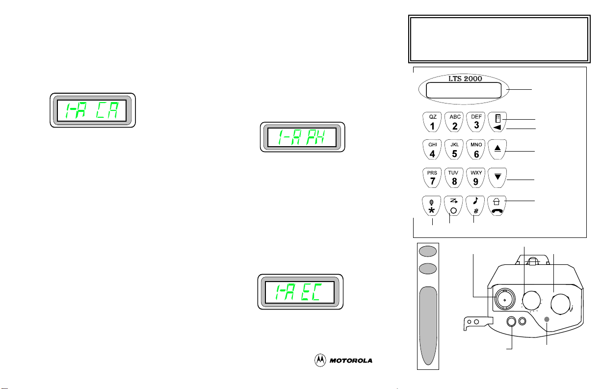
Press the PTT switch to immediately carry out private conversation. Check user’s guide for operational options.
Receiving Call Alert
When call alert is received by a radio user, the display shows:
and the radio beeps every four seconds until you
acknowledge call alert by pressing any button or
PTT switch. Call alert will not be received when
the radio is engaged in voice conversation, has
been turned off, or is out of the system range.
Making a Call Alert
T o send a call alert, press repeatedly the call button
until CA is displayed. Press the PTT to send the
call alert. If you want to send call alert to another
ID, use the scroll up or scroll down buttons to display the required ID, and press the PTT switch.
Check user’s guide for operational options.
last number dialed. Press the PTT to send
the call. If you want to send to a new number, enter the digits of your required number ,
and press the PTT button to talk. Check
user’s guide for operational options.
Receiving a Call from Landline Telephone
When a radio receives a call from a landline
telephone, the display shows:
Press the phone button to answer the call.
The display shows “PHonE”. Press PTT
button to talk and release while listening.
Press the home button after your conversation is over.
Emergency Call
T o initiate an emergenc y call, press and hold
the emergency button (see figure) until a
short medium-pitched emergency tone is
heard. The display shows:
LTS 2000 Portable Radio
Quick Start
Scan
Light/Asterisk
Emerg
Select/
Delete
PC/CA
Antenna
Connector
Mode Selector Knob
Display
Menu
Backspace
Delete
System Up/
Scroll Up
System Down/
Scroll Down
Home/Phone
Vol Control/On/Off
Telephone Interconnect
Making a Call to Landline Telephone
Your radio is capable of providing a telephone
interconnect option that enables you to call landline telephones through the central system.
To make a call, press the phone button. The word
ACCESS is displayed momentarily and then the
To exit, press the emergency button until
two high pitched tones are heard.
Check user’s guide for operational options.
68P02946C10
PTT
Accessory
Connector
LED
Red - Transmit
Yellow - Receive
Blank - Standby
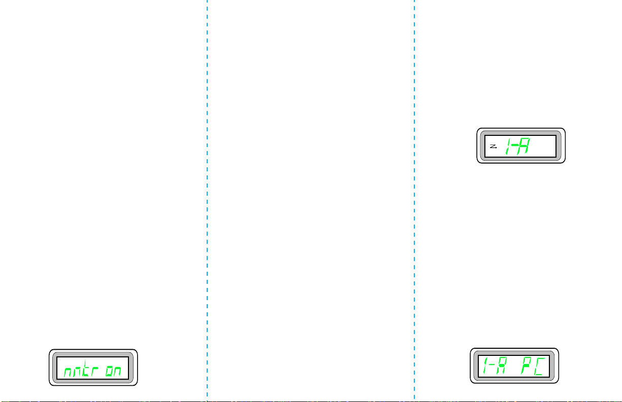
Getting Started
1. Install the battery.
2. Install the antenna.
3. Install the belt clip.
Basic Radio Operation
Turning the Radio On
Turn the on/off/volume control knob clockwise
until it clicks. The display will display all icons
and digits momentarily. You will hear a
after a successful power-up.
Receiving
1. Turn the radio ON and select the desired system and group for trunking, or desired mode
and channel for conventional.
2. Listen until you hear a activity, then adjust the
volume control for a comfortable listening
level.
3. Your radio is now set to receive calls on the
selected mode.
Monitoring a Conventional Channel
The monitoring feature is active on conventional
channels and is pre-programmed with PL or DPL
SQUELCH CODE for receiver frequencies. Select
menu by pressing the menu button. Press the menu
button repeatedly until the display shows:
chirp
tone
Press the select button located above the PTT
switch to enter squelch monitoring mode. The
monitoring icon will turn on and you will hear
activity on the channel. To cancel monitoring a
conventional channel, press the menu button
repeatedly until
select button, the monitor icon will disappear from
the display.
Transmitting on a Conventional Channel
1. Turn the radio on and check the channel for
activity (yellow LED).
2. When clear, press PTT and speak into microphone area. The red LED will illuminate continuously while transmitting.
3. Check user’s guide for operational options.
Transmitting on a Trunked System
1. Turn the radio on and press PTT. If
(talk permit) tone is heard, continue to press
PTT and speak into microphone area. The red
LED will illuminate continuously while
transmitting.
2. Check user’s guide for operational options.
“monitor off”
is displayed. Press
dit-dit-dit
Radio Operation with Features
Muting Keypad Tones
1. Press menu button to select menu list.
2. Press the menu button repeatedly until
on
is displayed. Press the select button to
mute on
.
3. Radio saves mute state and returns to the
home display.
mute
turn
4. To deselect the mute state, press the menu
button until “mute off” is displayed, and
press the select button.
Scanning Operation
Turning Scan On
1. Select the desired home mode and press the
scan button to turn scan on.
2. The display shows:
Turning Scan Off
1. While scanning, press scan button.
2. A chirp will be heard and the scan icon will
disappear from the display.
Deleting Nuisance Modes
While scanning, a locked channel when displayed
can be temporarily deleted from the scan list by
pressing the select button. Scanning continues on
the remaining modes. To resume scanning on the
deleted mode, exit and reenter scan operation.
Receiving a Private Call
When you receive a private call, the incoming private call tone is heard, and the display shows:
This document was created with FrameMaker 4.0.4
 Loading...