

Page 1
Symbol LS7708
Product Reference Guide
Page 2

Page 3

Symbol LS7708
Product Reference Guide
72E-69531-02
Revision A
February 2007
Page 4

© Motorola, Inc. 2007. All rights reserved.
No part of this publication may be reproduced or used in any form, or by any electrical or mechanical means, without permission in writing from
Motorola. This includes electronic or mechanical means, such as photocopying, recording, or information storage and retrieval systems. The
material in this manual is subject to change without notice.
The software is provided strictly on an “as is” basis. All software, including firmware, furnished to the user is on a licensed basis. Motorola grants
to the user a non-transferable and non-exclusive license to use each software or firmware program delivered hereunder (licensed program). Except
as noted below, such license may not be assigned, sublicensed, or otherwise transferred by the user without prior written consent of Motorola.
No right to copy a licensed program in whole or in part is granted, except as permitted under copyright law. The user shall not modify, merge, or
incorporate any form or portion of a licensed program with other program material, create a derivative work from a licensed program, or use a
licensed program in a network without written permission from Motorola. The user agrees to maintain Motorola’s copyright notice on the licensed
programs delivered hereunder, and to include the same on any authorized copies it makes, in whole or in part. The user agrees not to decompile,
disassemble, decode, or reverse engineer any licensed program delivered to the user or any portion thereof.
Motorola reserves the right to make changes to any software or product to improve reliability, function, or design.
Motorola does not assume any product liability arising out of, or in connection with, the application or use of any product, circuit, or application
described herein.
No license is granted, either expressly or by implication, estoppel, or otherwise under any Motorola intellectual property rights. An implied license
only exists for equipment, circuits, and subsystems contained in Motorola products.
MOTOROLA and the Stylized M Logo are registered in the US Patent & Trademark Office. Symbol is a registered trademark of Symbol Technologies,
Inc. All other product or service names are the property of their respective owners.
Motorola
One Symbol Plaza
Holtsville, New York 11742-1300
http://www.symbol.com
Page 5

Revision History
Changes to the original manual are listed below:
Change Date Description
72E-69531-01 9/2004 Initial release.
72E-69413-02 2/2007 Update service information, add parameter bar codes for Bookland ISBN, new
UPC supplemental decode options, report software version, report MIMIC
version, report Synapse cable
Page 6

Page 7

Contents
About This Guide
Introduction . . . . . . . . . . . . . . . . . . . . . . . . . . . . . . . . . . . . . . . . . . . . . . . . . . . . . . . . . . . . . . . . . . . . . . . . . . . . . xv
Chapter Descriptions . . . . . . . . . . . . . . . . . . . . . . . . . . . . . . . . . . . . . . . . . . . . . . . . . . . . . . . . . . . . . . . . . . . . . . .xv
Notational Conventions . . . . . . . . . . . . . . . . . . . . . . . . . . . . . . . . . . . . . . . . . . . . . . . . . . . . . . . . . . . . . . . . . . . . xvi
Related Publications. . . . . . . . . . . . . . . . . . . . . . . . . . . . . . . . . . . . . . . . . . . . . . . . . . . . . . . . . . . . . . . . . . . . . . . xvi
Service Information . . . . . . . . . . . . . . . . . . . . . . . . . . . . . . . . . . . . . . . . . . . . . . . . . . . . . . . . . . . . . . . . . . . . . . . xvi
Chapter 1. Getting Started
Introduction . . . . . . . . . . . . . . . . . . . . . . . . . . . . . . . . . . . . . . . . . . . . . . . . . . . . . . . . . . . . . . . . . . . . . . . . . . . . 1-3
Unpacking the Scanner . . . . . . . . . . . . . . . . . . . . . . . . . . . . . . . . . . . . . . . . . . . . . . . . . . . . . . . . . . . . . . . . . . . .1-4
Input/Output Ports . . . . . . . . . . . . . . . . . . . . . . . . . . . . . . . . . . . . . . . . . . . . . . . . . . . . . . . . . . . . . . . . . . . . . . . .1-5
Setting Up the Scanner . . . . . . . . . . . . . . . . . . . . . . . . . . . . . . . . . . . . . . . . . . . . . . . . . . . . . . . . . . . . . . . . . . . . 1-6
Power Options . . . . . . . . . . . . . . . . . . . . . . . . . . . . . . . . . . . . . . . . . . . . . . . . . . . . . . . . . . . . . . . . . . . . . . .1-6
Connecting the Host and Peripheral Cables . . . . . . . . . . . . . . . . . . . . . . . . . . . . . . . . . . . . . . . . . . . . . . . .1-6
Routing Cables . . . . . . . . . . . . . . . . . . . . . . . . . . . . . . . . . . . . . . . . . . . . . . . . . . . . . . . . . . . . . . . . . . . . . . . . . . .1-8
Removing the Host Interface Cable . . . . . . . . . . . . . . . . . . . . . . . . . . . . . . . . . . . . . . . . . . . . . . . . . . . . . . .1-8
Configuring the Scanner. . . . . . . . . . . . . . . . . . . . . . . . . . . . . . . . . . . . . . . . . . . . . . . . . . . . . . . . . . . . . . . .1-9
Synchronization of Settings . . . . . . . . . . . . . . . . . . . . . . . . . . . . . . . . . . . . . . . . . . . . . . . . . . . . . . . . . . . . .1-9
Mounting the Scanner to a Surface. . . . . . . . . . . . . . . . . . . . . . . . . . . . . . . . . . . . . . . . . . . . . . . . . . . . . . . . . . 1-10
Attaching the Mounting Bracket . . . . . . . . . . . . . . . . . . . . . . . . . . . . . . . . . . . . . . . . . . . . . . . . . . . . . . . . 1-10
Detaching the Scanner from the Mounting Bracket . . . . . . . . . . . . . . . . . . . . . . . . . . . . . . . . . . . . . . . . .1-13
Chapter 2. Scanning
Introduction . . . . . . . . . . . . . . . . . . . . . . . . . . . . . . . . . . . . . . . . . . . . . . . . . . . . . . . . . . . . . . . . . . . . . . . . . . . . 2-3
Page 8

Symbol LS7708 Product Reference Guidevi
Active Scan Area . . . . . . . . . . . . . . . . . . . . . . . . . . . . . . . . . . . . . . . . . . . . . . . . . . . . . . . . . . . . . . . . . . . . . . . . .2-3
Scanning Bar Codes . . . . . . . . . . . . . . . . . . . . . . . . . . . . . . . . . . . . . . . . . . . . . . . . . . . . . . . . . . . . . . . . . . . . . . .2-3
Beeper Definitions . . . . . . . . . . . . . . . . . . . . . . . . . . . . . . . . . . . . . . . . . . . . . . . . . . . . . . . . . . . . . . . . . . . . . . . .2-5
Selecting Beeper Volume . . . . . . . . . . . . . . . . . . . . . . . . . . . . . . . . . . . . . . . . . . . . . . . . . . . . . . . . . . . . . . . . . . .2-6
Sleep Mode. . . . . . . . . . . . . . . . . . . . . . . . . . . . . . . . . . . . . . . . . . . . . . . . . . . . . . . . . . . . . . . . . . . . . . . . . . . . . .2-6
LED Definitions . . . . . . . . . . . . . . . . . . . . . . . . . . . . . . . . . . . . . . . . . . . . . . . . . . . . . . . . . . . . . . . . . . . . . . . . . . .2-6
Decode Zone. . . . . . . . . . . . . . . . . . . . . . . . . . . . . . . . . . . . . . . . . . . . . . . . . . . . . . . . . . . . . . . . . . . . . . . . . . . . .2-7
Integrated Electronic Article Surveillance (EAS) . . . . . . . . . . . . . . . . . . . . . . . . . . . . . . . . . . . . . . . . . . . . . . . . .2-8
LS7708 Interlock Cable and EAS . . . . . . . . . . . . . . . . . . . . . . . . . . . . . . . . . . . . . . . . . . . . . . . . . . . . . . . . .2-8
Installing the Electronic Article Surveillance (EAS) . . . . . . . . . . . . . . . . . . . . . . . . . . . . . . . . . . . . . . . . . . . . . . .2-8
CheckPoint EAS Model Compatibility . . . . . . . . . . . . . . . . . . . . . . . . . . . . . . . . . . . . . . . . . . . . . . . . . . . . .2-8
Considerations . . . . . . . . . . . . . . . . . . . . . . . . . . . . . . . . . . . . . . . . . . . . . . . . . . . . . . . . . . . . . . . . . . . . . . .2-8
CheckPoint Contact Information. . . . . . . . . . . . . . . . . . . . . . . . . . . . . . . . . . . . . . . . . . . . . . . . . . . . . . . . . .2-8
Deactivation for Sensormatic EAS System . . . . . . . . . . . . . . . . . . . . . . . . . . . . . . . . . . . . . . . . . . . . . . . . .2-8
Chapter 3. Maintenance and Technical Specifications
Introduction. . . . . . . . . . . . . . . . . . . . . . . . . . . . . . . . . . . . . . . . . . . . . . . . . . . . . . . . . . . . . . . . . . . . . . . . . . . . . 3-3
Maintenance. . . . . . . . . . . . . . . . . . . . . . . . . . . . . . . . . . . . . . . . . . . . . . . . . . . . . . . . . . . . . . . . . . . . . . . . . . . . .3-3
Replacing the Scanner Window. . . . . . . . . . . . . . . . . . . . . . . . . . . . . . . . . . . . . . . . . . . . . . . . . . . . . . . . . . . . . .3-4
Troubleshooting . . . . . . . . . . . . . . . . . . . . . . . . . . . . . . . . . . . . . . . . . . . . . . . . . . . . . . . . . . . . . . . . . . . . . . . . . .3-6
Technical Specifications. . . . . . . . . . . . . . . . . . . . . . . . . . . . . . . . . . . . . . . . . . . . . . . . . . . . . . . . . . . . . . . . . . . .3-7
Scanner Signal Descriptions. . . . . . . . . . . . . . . . . . . . . . . . . . . . . . . . . . . . . . . . . . . . . . . . . . . . . . . . . . . . . . . . .3-9
Chapter 4. User Preferences
Introduction. . . . . . . . . . . . . . . . . . . . . . . . . . . . . . . . . . . . . . . . . . . . . . . . . . . . . . . . . . . . . . . . . . . . . . . . . . . . . 4-3
Scanning Sequence Examples . . . . . . . . . . . . . . . . . . . . . . . . . . . . . . . . . . . . . . . . . . . . . . . . . . . . . . . . . . . . . . .4-3
Errors While Scanning . . . . . . . . . . . . . . . . . . . . . . . . . . . . . . . . . . . . . . . . . . . . . . . . . . . . . . . . . . . . . . . . . . . . .4-3
User Preferences Default Parameters . . . . . . . . . . . . . . . . . . . . . . . . . . . . . . . . . . . . . . . . . . . . . . . . . . . . . . . . .4-3
User Preferences. . . . . . . . . . . . . . . . . . . . . . . . . . . . . . . . . . . . . . . . . . . . . . . . . . . . . . . . . . . . . . . . . . . . . . . . . .4-5
Set Default Parameter . . . . . . . . . . . . . . . . . . . . . . . . . . . . . . . . . . . . . . . . . . . . . . . . . . . . . . . . . . . . . . . . .4-5
Beeper Tone . . . . . . . . . . . . . . . . . . . . . . . . . . . . . . . . . . . . . . . . . . . . . . . . . . . . . . . . . . . . . . . . . . . . . . . . .4-5
Beeper Volume . . . . . . . . . . . . . . . . . . . . . . . . . . . . . . . . . . . . . . . . . . . . . . . . . . . . . . . . . . . . . . . . . . . . . . .4-7
Beep After Good Decode . . . . . . . . . . . . . . . . . . . . . . . . . . . . . . . . . . . . . . . . . . . . . . . . . . . . . . . . . . . . . . .4-9
Low Power Mode . . . . . . . . . . . . . . . . . . . . . . . . . . . . . . . . . . . . . . . . . . . . . . . . . . . . . . . . . . . . . . . . . . . .4-10
Scan Pattern Mode. . . . . . . . . . . . . . . . . . . . . . . . . . . . . . . . . . . . . . . . . . . . . . . . . . . . . . . . . . . . . . . . . . .4-11
Timeout Between Decodes . . . . . . . . . . . . . . . . . . . . . . . . . . . . . . . . . . . . . . . . . . . . . . . . . . . . . . . . . . . .4-12
Time Delay to Low Power Mode . . . . . . . . . . . . . . . . . . . . . . . . . . . . . . . . . . . . . . . . . . . . . . . . . . . . . . . .4-13
Linear UPC/EAN Decode . . . . . . . . . . . . . . . . . . . . . . . . . . . . . . . . . . . . . . . . . . . . . . . . . . . . . . . . . . . . . .4-15
UPC Half Block Stitching . . . . . . . . . . . . . . . . . . . . . . . . . . . . . . . . . . . . . . . . . . . . . . . . . . . . . . . . . . . . . .4-16
EAS Interlock . . . . . . . . . . . . . . . . . . . . . . . . . . . . . . . . . . . . . . . . . . . . . . . . . . . . . . . . . . . . . . . . . . . . . . .4-17
Chapter 5. Keyboard Wedge Interface
Introduction. . . . . . . . . . . . . . . . . . . . . . . . . . . . . . . . . . . . . . . . . . . . . . . . . . . . . . . . . . . . . . . . . . . . . . . . . . . . . 5-3
Connecting a Keyboard Wedge Interface. . . . . . . . . . . . . . . . . . . . . . . . . . . . . . . . . . . . . . . . . . . . . . . . . . . . . . .5-4
Keyboard Wedge Default Parameters . . . . . . . . . . . . . . . . . . . . . . . . . . . . . . . . . . . . . . . . . . . . . . . . . . . . . . . . .5-6
Keyboard Wedge Host Types . . . . . . . . . . . . . . . . . . . . . . . . . . . . . . . . . . . . . . . . . . . . . . . . . . . . . . . . . . . .5-7
Keyboard Wedge Country Types (Country Codes) . . . . . . . . . . . . . . . . . . . . . . . . . . . . . . . . . . . . . . . . . . . .5-9
Page 9

Ignore Unknown Characters. . . . . . . . . . . . . . . . . . . . . . . . . . . . . . . . . . . . . . . . . . . . . . . . . . . . . . . . . . . .5-14
Keystroke Delay . . . . . . . . . . . . . . . . . . . . . . . . . . . . . . . . . . . . . . . . . . . . . . . . . . . . . . . . . . . . . . . . . . . . .5-15
Intra-Keystroke Delay. . . . . . . . . . . . . . . . . . . . . . . . . . . . . . . . . . . . . . . . . . . . . . . . . . . . . . . . . . . . . . . . .5-17
Alternate Numeric Keypad Emulation . . . . . . . . . . . . . . . . . . . . . . . . . . . . . . . . . . . . . . . . . . . . . . . . . . . .5-18
Caps Lock On . . . . . . . . . . . . . . . . . . . . . . . . . . . . . . . . . . . . . . . . . . . . . . . . . . . . . . . . . . . . . . . . . . . . . . .5-19
Caps Lock Override. . . . . . . . . . . . . . . . . . . . . . . . . . . . . . . . . . . . . . . . . . . . . . . . . . . . . . . . . . . . . . . . . . .5-20
Convert Wedge Data . . . . . . . . . . . . . . . . . . . . . . . . . . . . . . . . . . . . . . . . . . . . . . . . . . . . . . . . . . . . . . . . .5-21
Function Key Mapping . . . . . . . . . . . . . . . . . . . . . . . . . . . . . . . . . . . . . . . . . . . . . . . . . . . . . . . . . . . . . . . .5-23
FN1 Substitution. . . . . . . . . . . . . . . . . . . . . . . . . . . . . . . . . . . . . . . . . . . . . . . . . . . . . . . . . . . . . . . . . . . . .5-24
Send Make Break . . . . . . . . . . . . . . . . . . . . . . . . . . . . . . . . . . . . . . . . . . . . . . . . . . . . . . . . . . . . . . . . . . . .5-25
OnKeyboard Maps . . . . . . . . . . . . . . . . . . . . . . . . . . . . . . . . . . . . . . . . . . . . . . . . . . . . . . . . . . . . . . . . . . .5-26
ASCII Character Set . . . . . . . . . . . . . . . . . . . . . . . . . . . . . . . . . . . . . . . . . . . . . . . . . . . . . . . . . . . . . . . . . . . . . .5-28
Chapter 6. RS-232 Host Interface
Introduction. . . . . . . . . . . . . . . . . . . . . . . . . . . . . . . . . . . . . . . . . . . . . . . . . . . . . . . . . . . . . . . . . . . . . . . . . . . . . 6-3
Connecting an RS-232 Interface. . . . . . . . . . . . . . . . . . . . . . . . . . . . . . . . . . . . . . . . . . . . . . . . . . . . . . . . . . . . . .6-4
RS-232 Default Parameters . . . . . . . . . . . . . . . . . . . . . . . . . . . . . . . . . . . . . . . . . . . . . . . . . . . . . . . . . . . . . . . . .6-6
RS-232 Host Parameters . . . . . . . . . . . . . . . . . . . . . . . . . . . . . . . . . . . . . . . . . . . . . . . . . . . . . . . . . . . . . . . . . . .6-7
RS-232 Host Types . . . . . . . . . . . . . . . . . . . . . . . . . . . . . . . . . . . . . . . . . . . . . . . . . . . . . . . . . . . . . . . . . . . .6-9
Baud Rate . . . . . . . . . . . . . . . . . . . . . . . . . . . . . . . . . . . . . . . . . . . . . . . . . . . . . . . . . . . . . . . . . . . . . . . . . .6-13
Parity. . . . . . . . . . . . . . . . . . . . . . . . . . . . . . . . . . . . . . . . . . . . . . . . . . . . . . . . . . . . . . . . . . . . . . . . . . . . . .6-17
Check Receive Errors . . . . . . . . . . . . . . . . . . . . . . . . . . . . . . . . . . . . . . . . . . . . . . . . . . . . . . . . . . . . . . . . .6-20
Hardware Handshaking . . . . . . . . . . . . . . . . . . . . . . . . . . . . . . . . . . . . . . . . . . . . . . . . . . . . . . . . . . . . . . .6-21
Software Handshaking. . . . . . . . . . . . . . . . . . . . . . . . . . . . . . . . . . . . . . . . . . . . . . . . . . . . . . . . . . . . . . . .6-24
Host Serial Response Time-out . . . . . . . . . . . . . . . . . . . . . . . . . . . . . . . . . . . . . . . . . . . . . . . . . . . . . . . . .6-26
RTS Line State . . . . . . . . . . . . . . . . . . . . . . . . . . . . . . . . . . . . . . . . . . . . . . . . . . . . . . . . . . . . . . . . . . . . . .6-29
Stop Bit Select . . . . . . . . . . . . . . . . . . . . . . . . . . . . . . . . . . . . . . . . . . . . . . . . . . . . . . . . . . . . . . . . . . . . . .6-30
Data Bits. . . . . . . . . . . . . . . . . . . . . . . . . . . . . . . . . . . . . . . . . . . . . . . . . . . . . . . . . . . . . . . . . . . . . . . . . . .6-31
Beep on <BEL> . . . . . . . . . . . . . . . . . . . . . . . . . . . . . . . . . . . . . . . . . . . . . . . . . . . . . . . . . . . . . . . . . . . . . .6-32
Intercharacter Delay. . . . . . . . . . . . . . . . . . . . . . . . . . . . . . . . . . . . . . . . . . . . . . . . . . . . . . . . . . . . . . . . . .6-33
Nixdorf Beep/LED Options . . . . . . . . . . . . . . . . . . . . . . . . . . . . . . . . . . . . . . . . . . . . . . . . . . . . . . . . . . . . .6-35
Ignore Unknown Characters. . . . . . . . . . . . . . . . . . . . . . . . . . . . . . . . . . . . . . . . . . . . . . . . . . . . . . . . . . . .6-37
ASCII / Character Set . . . . . . . . . . . . . . . . . . . . . . . . . . . . . . . . . . . . . . . . . . . . . . . . . . . . . . . . . . . . . . . . . . . . .6-38
Contents vii
Chapter 7. USB Interface
Introduction. . . . . . . . . . . . . . . . . . . . . . . . . . . . . . . . . . . . . . . . . . . . . . . . . . . . . . . . . . . . . . . . . . . . . . . . . . . . . 7-3
Connecting a USB Interface . . . . . . . . . . . . . . . . . . . . . . . . . . . . . . . . . . . . . . . . . . . . . . . . . . . . . . . . . . . . . . . . .7-3
USB Default Parameters. . . . . . . . . . . . . . . . . . . . . . . . . . . . . . . . . . . . . . . . . . . . . . . . . . . . . . . . . . . . . . . . . . . .7-6
USB Host Parameters . . . . . . . . . . . . . . . . . . . . . . . . . . . . . . . . . . . . . . . . . . . . . . . . . . . . . . . . . . . . . . . . . . . . . .7-7
USB Device Type . . . . . . . . . . . . . . . . . . . . . . . . . . . . . . . . . . . . . . . . . . . . . . . . . . . . . . . . . . . . . . . . . . . . .7-7
USB Country Keyboard Types (Country Codes) . . . . . . . . . . . . . . . . . . . . . . . . . . . . . . . . . . . . . . . . . . . . . .7-9
USB Keystroke Delay . . . . . . . . . . . . . . . . . . . . . . . . . . . . . . . . . . . . . . . . . . . . . . . . . . . . . . . . . . . . . . . . .7-14
USB CAPS Lock Override . . . . . . . . . . . . . . . . . . . . . . . . . . . . . . . . . . . . . . . . . . . . . . . . . . . . . . . . . . . . . .7-16
USB Ignore Unknown Characters. . . . . . . . . . . . . . . . . . . . . . . . . . . . . . . . . . . . . . . . . . . . . . . . . . . . . . . .7-17
Emulate Keypad . . . . . . . . . . . . . . . . . . . . . . . . . . . . . . . . . . . . . . . . . . . . . . . . . . . . . . . . . . . . . . . . . . . . .7-18
USB Keyboard FN1 Substitution. . . . . . . . . . . . . . . . . . . . . . . . . . . . . . . . . . . . . . . . . . . . . . . . . . . . . . . . .7-19
Function Key Mapping . . . . . . . . . . . . . . . . . . . . . . . . . . . . . . . . . . . . . . . . . . . . . . . . . . . . . . . . . . . . . . . .7-20
Simulated Caps Lock . . . . . . . . . . . . . . . . . . . . . . . . . . . . . . . . . . . . . . . . . . . . . . . . . . . . . . . . . . . . . . . . .7-21
Page 10

Symbol LS7708 Product Reference Guideviii
Convert Case. . . . . . . . . . . . . . . . . . . . . . . . . . . . . . . . . . . . . . . . . . . . . . . . . . . . . . . . . . . . . . . . . . . . . . . .7-22
ASCII Character Set . . . . . . . . . . . . . . . . . . . . . . . . . . . . . . . . . . . . . . . . . . . . . . . . . . . . . . . . . . . . . . . . . . . . . .7-24
Chapter 8. IBM 468X/469X Interface
Introduction. . . . . . . . . . . . . . . . . . . . . . . . . . . . . . . . . . . . . . . . . . . . . . . . . . . . . . . . . . . . . . . . . . . . . . . . . . . . . 8-3
Connecting to an IBM 468X/469X Host . . . . . . . . . . . . . . . . . . . . . . . . . . . . . . . . . . . . . . . . . . . . . . . . . . . . . . . .8-4
IBM Default Parameters. . . . . . . . . . . . . . . . . . . . . . . . . . . . . . . . . . . . . . . . . . . . . . . . . . . . . . . . . . . . . . . . . . . .8-5
IBM 468X/469X Host Parameters . . . . . . . . . . . . . . . . . . . . . . . . . . . . . . . . . . . . . . . . . . . . . . . . . . . . . . . . . . . .8-6
Port Address . . . . . . . . . . . . . . . . . . . . . . . . . . . . . . . . . . . . . . . . . . . . . . . . . . . . . . . . . . . . . . . . . . . . . . . . .8-6
Convert Unknown to Code 39. . . . . . . . . . . . . . . . . . . . . . . . . . . . . . . . . . . . . . . . . . . . . . . . . . . . . . . . . . . .8-8
Chapter 9. Synapse Interface
Introduction. . . . . . . . . . . . . . . . . . . . . . . . . . . . . . . . . . . . . . . . . . . . . . . . . . . . . . . . . . . . . . . . . . . . . . . . . . . . . 9-3
Connecting a Synapse Interface Cable. . . . . . . . . . . . . . . . . . . . . . . . . . . . . . . . . . . . . . . . . . . . . . . . . . . . . . . . .9-5
Synapse Interface. . . . . . . . . . . . . . . . . . . . . . . . . . . . . . . . . . . . . . . . . . . . . . . . . . . . . . . . . . . . . . . . . . . . .9-6
“Plug and Play” Synapse Connection. . . . . . . . . . . . . . . . . . . . . . . . . . . . . . . . . . . . . . . . . . . . . . . . . . . . . .9-6
Chapter 10. RS-232 Auxiliary Port
Introduction. . . . . . . . . . . . . . . . . . . . . . . . . . . . . . . . . . . . . . . . . . . . . . . . . . . . . . . . . . . . . . . . . . . . . . . . . . . . 10-3
Connecting a Device to the RS-232 Auxiliary Port. . . . . . . . . . . . . . . . . . . . . . . . . . . . . . . . . . . . . . . . . . . . . . .10-4
RS-232 Auxiliary Port Default Parameters . . . . . . . . . . . . . . . . . . . . . . . . . . . . . . . . . . . . . . . . . . . . . . . . . . . . .10-5
RS-232 Auxiliary Port Parameters . . . . . . . . . . . . . . . . . . . . . . . . . . . . . . . . . . . . . . . . . . . . . . . . . . . . . . . . . . .10-6
Baud Rate . . . . . . . . . . . . . . . . . . . . . . . . . . . . . . . . . . . . . . . . . . . . . . . . . . . . . . . . . . . . . . . . . . . . . . . . . .10-6
Parity. . . . . . . . . . . . . . . . . . . . . . . . . . . . . . . . . . . . . . . . . . . . . . . . . . . . . . . . . . . . . . . . . . . . . . . . . . . . . .10-9
Check Receive Errors . . . . . . . . . . . . . . . . . . . . . . . . . . . . . . . . . . . . . . . . . . . . . . . . . . . . . . . . . . . . . . . .10-11
Check Receive Errors (continued) . . . . . . . . . . . . . . . . . . . . . . . . . . . . . . . . . . . . . . . . . . . . . . . . . . . . . . .10-12
Hardware Handshaking . . . . . . . . . . . . . . . . . . . . . . . . . . . . . . . . . . . . . . . . . . . . . . . . . . . . . . . . . . . . . .10-12
Standard RTS/CTS . . . . . . . . . . . . . . . . . . . . . . . . . . . . . . . . . . . . . . . . . . . . . . . . . . . . . . . . . . . . . . . . . .10-13
Software Handshaking . . . . . . . . . . . . . . . . . . . . . . . . . . . . . . . . . . . . . . . . . . . . . . . . . . . . . . . . . . . . . . .10-15
Serial Response Time-out . . . . . . . . . . . . . . . . . . . . . . . . . . . . . . . . . . . . . . . . . . . . . . . . . . . . . . . . . . . .10-17
RTS Line State . . . . . . . . . . . . . . . . . . . . . . . . . . . . . . . . . . . . . . . . . . . . . . . . . . . . . . . . . . . . . . . . . . . . .10-20
Stop Bit Select . . . . . . . . . . . . . . . . . . . . . . . . . . . . . . . . . . . . . . . . . . . . . . . . . . . . . . . . . . . . . . . . . . . . .10-21
Data Bits . . . . . . . . . . . . . . . . . . . . . . . . . . . . . . . . . . . . . . . . . . . . . . . . . . . . . . . . . . . . . . . . . . . . . . . . . .10-22
Chapter 11. Hand-Held Laser Scanner Port
Introduction. . . . . . . . . . . . . . . . . . . . . . . . . . . . . . . . . . . . . . . . . . . . . . . . . . . . . . . . . . . . . . . . . . . . . . . . . . . . 11-3
Connecting a Hand-Held Scanner . . . . . . . . . . . . . . . . . . . . . . . . . . . . . . . . . . . . . . . . . . . . . . . . . . . . . . .11-3
Hand-Held Laser Scanner Default Parameters . . . . . . . . . . . . . . . . . . . . . . . . . . . . . . . . . . . . . . . . . . . . .11-4
Hand-Held Laser Scanner Options . . . . . . . . . . . . . . . . . . . . . . . . . . . . . . . . . . . . . . . . . . . . . . . . . . . . . . . . . . .11-5
Programming Mode . . . . . . . . . . . . . . . . . . . . . . . . . . . . . . . . . . . . . . . . . . . . . . . . . . . . . . . . . . . . . . . . . .11-5
Beep After Good Decode . . . . . . . . . . . . . . . . . . . . . . . . . . . . . . . . . . . . . . . . . . . . . . . . . . . . . . . . . . . . . .11-7
Chapter 12. 123Scan
Introduction. . . . . . . . . . . . . . . . . . . . . . . . . . . . . . . . . . . . . . . . . . . . . . . . . . . . . . . . . . . . . . . . . . . . . . . . . . . . 12-3
Setting Up the 123Scan PC-Based Configuration Tool . . . . . . . . . . . . . . . . . . . . . . . . . . . . . . . . . . . . . . . . . . .12-3
123Scan Parameter. . . . . . . . . . . . . . . . . . . . . . . . . . . . . . . . . . . . . . . . . . . . . . . . . . . . . . . . . . . . . . . . . . . . . . .12-3
Page 11

Chapter 13. Symbologies
Introduction. . . . . . . . . . . . . . . . . . . . . . . . . . . . . . . . . . . . . . . . . . . . . . . . . . . . . . . . . . . . . . . . . . . . . . . . . . . . 13-3
Scanning Sequence Examples . . . . . . . . . . . . . . . . . . . . . . . . . . . . . . . . . . . . . . . . . . . . . . . . . . . . . . . . . . . . . .13-3
Errors While Scanning . . . . . . . . . . . . . . . . . . . . . . . . . . . . . . . . . . . . . . . . . . . . . . . . . . . . . . . . . . . . . . . . . . . .13-3
Symbology Default Parameters . . . . . . . . . . . . . . . . . . . . . . . . . . . . . . . . . . . . . . . . . . . . . . . . . . . . . . . . . . . . .13-3
UPC/EAN. . . . . . . . . . . . . . . . . . . . . . . . . . . . . . . . . . . . . . . . . . . . . . . . . . . . . . . . . . . . . . . . . . . . . . . . . . . . . . .13-7
Enable/Disable UPC-A/UPC-E . . . . . . . . . . . . . . . . . . . . . . . . . . . . . . . . . . . . . . . . . . . . . . . . . . . . . . . . . .13-7
Enable/Disable UPC-E1 . . . . . . . . . . . . . . . . . . . . . . . . . . . . . . . . . . . . . . . . . . . . . . . . . . . . . . . . . . . . . . .13-9
Enable/Disable EAN-13/JAN-13/EAN-8/JAN-8 . . . . . . . . . . . . . . . . . . . . . . . . . . . . . . . . . . . . . . . . . . .13-10
Enable/Disable Bookland EAN. . . . . . . . . . . . . . . . . . . . . . . . . . . . . . . . . . . . . . . . . . . . . . . . . . . . . . . . .13-12
Decode UPC/EAN Supplementals . . . . . . . . . . . . . . . . . . . . . . . . . . . . . . . . . . . . . . . . . . . . . . . . . . . . . .13-13
UPC/EAN Supplemental Redundancy . . . . . . . . . . . . . . . . . . . . . . . . . . . . . . . . . . . . . . . . . . . . . . . . . . .13-22
Transmit UPC-A/UPC-E/UPC-E1 Check Digit . . . . . . . . . . . . . . . . . . . . . . . . . . . . . . . . . . . . . . . . . . . . . .13-23
UPC-A Preamble . . . . . . . . . . . . . . . . . . . . . . . . . . . . . . . . . . . . . . . . . . . . . . . . . . . . . . . . . . . . . . . . . . . .13-26
UPC-E Preamble . . . . . . . . . . . . . . . . . . . . . . . . . . . . . . . . . . . . . . . . . . . . . . . . . . . . . . . . . . . . . . . . . . . .13-27
UPC-E1 Preamble . . . . . . . . . . . . . . . . . . . . . . . . . . . . . . . . . . . . . . . . . . . . . . . . . . . . . . . . . . . . . . . . . . .13-29
Convert UPC-E to UPC-A. . . . . . . . . . . . . . . . . . . . . . . . . . . . . . . . . . . . . . . . . . . . . . . . . . . . . . . . . . . . . .13-31
Convert UPC-E1 to UPC-A. . . . . . . . . . . . . . . . . . . . . . . . . . . . . . . . . . . . . . . . . . . . . . . . . . . . . . . . . . . . .13-32
EAN Zero Extend. . . . . . . . . . . . . . . . . . . . . . . . . . . . . . . . . . . . . . . . . . . . . . . . . . . . . . . . . . . . . . . . . . . .13-33
Bookland ISBN Format . . . . . . . . . . . . . . . . . . . . . . . . . . . . . . . . . . . . . . . . . . . . . . . . . . . . . . . . . . . . . . .13-34
UCC Coupon Extended Code. . . . . . . . . . . . . . . . . . . . . . . . . . . . . . . . . . . . . . . . . . . . . . . . . . . . . . . . . . .13-35
Code 128. . . . . . . . . . . . . . . . . . . . . . . . . . . . . . . . . . . . . . . . . . . . . . . . . . . . . . . . . . . . . . . . . . . . . . . . . . . . . .13-36
Enable/Disable Code 128. . . . . . . . . . . . . . . . . . . . . . . . . . . . . . . . . . . . . . . . . . . . . . . . . . . . . . . . . . . . .13-36
Enable/Disable UCC/EAN-128 . . . . . . . . . . . . . . . . . . . . . . . . . . . . . . . . . . . . . . . . . . . . . . . . . . . . . . . . .13-37
Enable/Disable ISBT 128 . . . . . . . . . . . . . . . . . . . . . . . . . . . . . . . . . . . . . . . . . . . . . . . . . . . . . . . . . . . . .13-38
Code 128 Decode Performance . . . . . . . . . . . . . . . . . . . . . . . . . . . . . . . . . . . . . . . . . . . . . . . . . . . . . . . .13-39
Code 128 Decode Performance Level. . . . . . . . . . . . . . . . . . . . . . . . . . . . . . . . . . . . . . . . . . . . . . . . . . . .13-40
Code 39. . . . . . . . . . . . . . . . . . . . . . . . . . . . . . . . . . . . . . . . . . . . . . . . . . . . . . . . . . . . . . . . . . . . . . . . . . . . . . .13-42
Enable/Disable Code 39. . . . . . . . . . . . . . . . . . . . . . . . . . . . . . . . . . . . . . . . . . . . . . . . . . . . . . . . . . . . . .13-42
Enable/Disable Trioptic Code 39 . . . . . . . . . . . . . . . . . . . . . . . . . . . . . . . . . . . . . . . . . . . . . . . . . . . . . . .13-43
Convert Code 39 to Code 32. . . . . . . . . . . . . . . . . . . . . . . . . . . . . . . . . . . . . . . . . . . . . . . . . . . . . . . . . . .13-44
Code 32 Prefix. . . . . . . . . . . . . . . . . . . . . . . . . . . . . . . . . . . . . . . . . . . . . . . . . . . . . . . . . . . . . . . . . . . . . .13-45
Set Lengths for Code 39. . . . . . . . . . . . . . . . . . . . . . . . . . . . . . . . . . . . . . . . . . . . . . . . . . . . . . . . . . . . . .13-46
Code 39 Check Digit Verification . . . . . . . . . . . . . . . . . . . . . . . . . . . . . . . . . . . . . . . . . . . . . . . . . . . . . . .13-48
Transmit Code 39 Check Digit . . . . . . . . . . . . . . . . . . . . . . . . . . . . . . . . . . . . . . . . . . . . . . . . . . . . . . . . .13-49
Enable/Disable Code 39 Full ASCII . . . . . . . . . . . . . . . . . . . . . . . . . . . . . . . . . . . . . . . . . . . . . . . . . . . . .13-50
Code 39 Buffering (Scan & Store) . . . . . . . . . . . . . . . . . . . . . . . . . . . . . . . . . . . . . . . . . . . . . . . . . . . . . .13-51
Code 39 Decode Performance . . . . . . . . . . . . . . . . . . . . . . . . . . . . . . . . . . . . . . . . . . . . . . . . . . . . . . . . .13-55
Code 39 Decode Performance Level. . . . . . . . . . . . . . . . . . . . . . . . . . . . . . . . . . . . . . . . . . . . . . . . . . . . .13-56
Code 93. . . . . . . . . . . . . . . . . . . . . . . . . . . . . . . . . . . . . . . . . . . . . . . . . . . . . . . . . . . . . . . . . . . . . . . . . . . . . . .13-58
Enable/Disable Code 93. . . . . . . . . . . . . . . . . . . . . . . . . . . . . . . . . . . . . . . . . . . . . . . . . . . . . . . . . . . . . .13-58
Set Lengths for Code 93. . . . . . . . . . . . . . . . . . . . . . . . . . . . . . . . . . . . . . . . . . . . . . . . . . . . . . . . . . . . . .13-59
Code 11. . . . . . . . . . . . . . . . . . . . . . . . . . . . . . . . . . . . . . . . . . . . . . . . . . . . . . . . . . . . . . . . . . . . . . . . . . . . . . .13-61
Enable/Disable Code 11. . . . . . . . . . . . . . . . . . . . . . . . . . . . . . . . . . . . . . . . . . . . . . . . . . . . . . . . . . . . . .13-61
Set Lengths for Code 11. . . . . . . . . . . . . . . . . . . . . . . . . . . . . . . . . . . . . . . . . . . . . . . . . . . . . . . . . . . . . .13-62
Code 11 Check Digit Verification . . . . . . . . . . . . . . . . . . . . . . . . . . . . . . . . . . . . . . . . . . . . . . . . . . . . . . .13-64
Transmit Code 11 Check Digits . . . . . . . . . . . . . . . . . . . . . . . . . . . . . . . . . . . . . . . . . . . . . . . . . . . . . . . .13-66
Interleaved 2 of 5 (ITF) . . . . . . . . . . . . . . . . . . . . . . . . . . . . . . . . . . . . . . . . . . . . . . . . . . . . . . . . . . . . . . . . . . .13-67
Contents ix
Page 12

Symbol LS7708 Product Reference Guidex
Enable/Disable Interleaved 2 of 5 . . . . . . . . . . . . . . . . . . . . . . . . . . . . . . . . . . . . . . . . . . . . . . . . . . . . . .13-67
Set Lengths for Interleaved 2 of 5 . . . . . . . . . . . . . . . . . . . . . . . . . . . . . . . . . . . . . . . . . . . . . . . . . . . . . .13-68
I 2 of 5 Check Digit Verification . . . . . . . . . . . . . . . . . . . . . . . . . . . . . . . . . . . . . . . . . . . . . . . . . . . . . . . .13-70
Transmit I 2 of 5 Check Digit . . . . . . . . . . . . . . . . . . . . . . . . . . . . . . . . . . . . . . . . . . . . . . . . . . . . . . . . . .13-72
Convert I 2 of 5 to EAN-13 . . . . . . . . . . . . . . . . . . . . . . . . . . . . . . . . . . . . . . . . . . . . . . . . . . . . . . . . . . . .13-73
Discrete 2 of 5 (DTF) . . . . . . . . . . . . . . . . . . . . . . . . . . . . . . . . . . . . . . . . . . . . . . . . . . . . . . . . . . . . . . . . . . . . .13-74
Enable/Disable Discrete 2 of 5. . . . . . . . . . . . . . . . . . . . . . . . . . . . . . . . . . . . . . . . . . . . . . . . . . . . . . . . .13-74
Set Lengths for Discrete 2 of 5. . . . . . . . . . . . . . . . . . . . . . . . . . . . . . . . . . . . . . . . . . . . . . . . . . . . . . . . .13-75
Codabar (NW - 7) . . . . . . . . . . . . . . . . . . . . . . . . . . . . . . . . . . . . . . . . . . . . . . . . . . . . . . . . . . . . . . . . . . . . . . .13-78
Enable/Disable Codabar. . . . . . . . . . . . . . . . . . . . . . . . . . . . . . . . . . . . . . . . . . . . . . . . . . . . . . . . . . . . . .13-78
Set Lengths for Codabar. . . . . . . . . . . . . . . . . . . . . . . . . . . . . . . . . . . . . . . . . . . . . . . . . . . . . . . . . . . . . .13-79
CLSI Editing. . . . . . . . . . . . . . . . . . . . . . . . . . . . . . . . . . . . . . . . . . . . . . . . . . . . . . . . . . . . . . . . . . . . . . . .13-82
NOTIS Editing . . . . . . . . . . . . . . . . . . . . . . . . . . . . . . . . . . . . . . . . . . . . . . . . . . . . . . . . . . . . . . . . . . . . . .13-83
RSS (Reduced Space Symbology). . . . . . . . . . . . . . . . . . . . . . . . . . . . . . . . . . . . . . . . . . . . . . . . . . . . . . . . . . .13-84
RSS 14 . . . . . . . . . . . . . . . . . . . . . . . . . . . . . . . . . . . . . . . . . . . . . . . . . . . . . . . . . . . . . . . . . . . . . . . . . . .13-84
RSS Limited . . . . . . . . . . . . . . . . . . . . . . . . . . . . . . . . . . . . . . . . . . . . . . . . . . . . . . . . . . . . . . . . . . . . . . .13-85
RSS Expanded. . . . . . . . . . . . . . . . . . . . . . . . . . . . . . . . . . . . . . . . . . . . . . . . . . . . . . . . . . . . . . . . . . . . . .13-86
Convert RSS to UPC/EAN . . . . . . . . . . . . . . . . . . . . . . . . . . . . . . . . . . . . . . . . . . . . . . . . . . . . . . . . . . . . .13-87
Symbology - Specific Security Levels. . . . . . . . . . . . . . . . . . . . . . . . . . . . . . . . . . . . . . . . . . . . . . . . . . . . . . . .13-88
Redundancy Level. . . . . . . . . . . . . . . . . . . . . . . . . . . . . . . . . . . . . . . . . . . . . . . . . . . . . . . . . . . . . . . . . . .13-88
Security Level . . . . . . . . . . . . . . . . . . . . . . . . . . . . . . . . . . . . . . . . . . . . . . . . . . . . . . . . . . . . . . . . . . . . . .13-91
Bi-directional Redundancy . . . . . . . . . . . . . . . . . . . . . . . . . . . . . . . . . . . . . . . . . . . . . . . . . . . . . . . . . . . .13-93
Symbology - Intercharacter Gap. . . . . . . . . . . . . . . . . . . . . . . . . . . . . . . . . . . . . . . . . . . . . . . . . . . . . . . . . . . .13-94
Chapter 14. Miscellaneous Scanner Options
Introduction. . . . . . . . . . . . . . . . . . . . . . . . . . . . . . . . . . . . . . . . . . . . . . . . . . . . . . . . . . . . . . . . . . . . . . . . . . . . 14-3
Scanning Sequence Examples . . . . . . . . . . . . . . . . . . . . . . . . . . . . . . . . . . . . . . . . . . . . . . . . . . . . . . . . . . . . . .14-3
Errors While Scanning . . . . . . . . . . . . . . . . . . . . . . . . . . . . . . . . . . . . . . . . . . . . . . . . . . . . . . . . . . . . . . . . . . . .14-3
Miscellaneous Default Parameters . . . . . . . . . . . . . . . . . . . . . . . . . . . . . . . . . . . . . . . . . . . . . . . . . . . . . . . . . .14-3
Miscellaneous Scanner Parameters. . . . . . . . . . . . . . . . . . . . . . . . . . . . . . . . . . . . . . . . . . . . . . . . . . . . . . . . . .14-4
Transmit Code ID Character . . . . . . . . . . . . . . . . . . . . . . . . . . . . . . . . . . . . . . . . . . . . . . . . . . . . . . . . . . . .14-4
Prefix/Suffix Values . . . . . . . . . . . . . . . . . . . . . . . . . . . . . . . . . . . . . . . . . . . . . . . . . . . . . . . . . . . . . . . . . .14-5
FN1 Substitution Values. . . . . . . . . . . . . . . . . . . . . . . . . . . . . . . . . . . . . . . . . . . . . . . . . . . . . . . . . . . . . . .14-6
Scan Data Options . . . . . . . . . . . . . . . . . . . . . . . . . . . . . . . . . . . . . . . . . . . . . . . . . . . . . . . . . . . . . . . . . . .14-7
Report Version . . . . . . . . . . . . . . . . . . . . . . . . . . . . . . . . . . . . . . . . . . . . . . . . . . . . . . . . . . . . . . . . . . . . .14-11
Report MIMIC Version . . . . . . . . . . . . . . . . . . . . . . . . . . . . . . . . . . . . . . . . . . . . . . . . . . . . . . . . . . . . . . .14-11
Report Synapse Cable . . . . . . . . . . . . . . . . . . . . . . . . . . . . . . . . . . . . . . . . . . . . . . . . . . . . . . . . . . . . . . .14-12
Appendix A. Standard Default Parameters
Appendix B. Programming Reference
Symbol Code Identifiers . . . . . . . . . . . . . . . . . . . . . . . . . . . . . . . . . . . . . . . . . . . . . . . . . . . . . . . . . . . . . . . . . . . B-3
AIM Code Identifiers. . . . . . . . . . . . . . . . . . . . . . . . . . . . . . . . . . . . . . . . . . . . . . . . . . . . . . . . . . . . . . . . . . . . . . B-4
Appendix C. Sample Bar Codes
Code 39. . . . . . . . . . . . . . . . . . . . . . . . . . . . . . . . . . . . . . . . . . . . . . . . . . . . . . . . . . . . . . . . . . . . . . . . . . . . . . . . C-3
Page 13

UPC/EAN. . . . . . . . . . . . . . . . . . . . . . . . . . . . . . . . . . . . . . . . . . . . . . . . . . . . . . . . . . . . . . . . . . . . . . . . . . . . . . . C-3
UPC-A, 100 %. . . . . . . . . . . . . . . . . . . . . . . . . . . . . . . . . . . . . . . . . . . . . . . . . . . . . . . . . . . . . . . . . . . . . . . C-3
EAN-13, 100 %. . . . . . . . . . . . . . . . . . . . . . . . . . . . . . . . . . . . . . . . . . . . . . . . . . . . . . . . . . . . . . . . . . . . . . C-4
Code 128. . . . . . . . . . . . . . . . . . . . . . . . . . . . . . . . . . . . . . . . . . . . . . . . . . . . . . . . . . . . . . . . . . . . . . . . . . . . . . . C-4
Interleaved 2 of 5 . . . . . . . . . . . . . . . . . . . . . . . . . . . . . . . . . . . . . . . . . . . . . . . . . . . . . . . . . . . . . . . . . . . . . . . . C-5
RSS 14 . . . . . . . . . . . . . . . . . . . . . . . . . . . . . . . . . . . . . . . . . . . . . . . . . . . . . . . . . . . . . . . . . . . . . . . . . . . . . . . . C-5
Appendix D. Numeric Bar Codes
0 . . . . . . . . . . . . . . . . . . . . . . . . . . . . . . . . . . . . . . . . . . . . . . . . . . . . . . . . . . . . . . . . . . . . . . . . . . . . . . . . . . . . . D-3
1 . . . . . . . . . . . . . . . . . . . . . . . . . . . . . . . . . . . . . . . . . . . . . . . . . . . . . . . . . . . . . . . . . . . . . . . . . . . . . . . . . . . . . D-3
2 . . . . . . . . . . . . . . . . . . . . . . . . . . . . . . . . . . . . . . . . . . . . . . . . . . . . . . . . . . . . . . . . . . . . . . . . . . . . . . . . . . . . . D-4
3 . . . . . . . . . . . . . . . . . . . . . . . . . . . . . . . . . . . . . . . . . . . . . . . . . . . . . . . . . . . . . . . . . . . . . . . . . . . . . . . . . . . . . D-4
4 . . . . . . . . . . . . . . . . . . . . . . . . . . . . . . . . . . . . . . . . . . . . . . . . . . . . . . . . . . . . . . . . . . . . . . . . . . . . . . . . . . . . . D-5
5 . . . . . . . . . . . . . . . . . . . . . . . . . . . . . . . . . . . . . . . . . . . . . . . . . . . . . . . . . . . . . . . . . . . . . . . . . . . . . . . . . . . . . D-5
6 . . . . . . . . . . . . . . . . . . . . . . . . . . . . . . . . . . . . . . . . . . . . . . . . . . . . . . . . . . . . . . . . . . . . . . . . . . . . . . . . . . . . . D-6
7 . . . . . . . . . . . . . . . . . . . . . . . . . . . . . . . . . . . . . . . . . . . . . . . . . . . . . . . . . . . . . . . . . . . . . . . . . . . . . . . . . . . . . D-6
8 . . . . . . . . . . . . . . . . . . . . . . . . . . . . . . . . . . . . . . . . . . . . . . . . . . . . . . . . . . . . . . . . . . . . . . . . . . . . . . . . . . . . . D-7
9 . . . . . . . . . . . . . . . . . . . . . . . . . . . . . . . . . . . . . . . . . . . . . . . . . . . . . . . . . . . . . . . . . . . . . . . . . . . . . . . . . . . . . D-7
Cancel . . . . . . . . . . . . . . . . . . . . . . . . . . . . . . . . . . . . . . . . . . . . . . . . . . . . . . . . . . . . . . . . . . . . . . . . . . . . . . . . . D-8
Contents xi
Appendix E. Mounting Template
Mounting Template . . . . . . . . . . . . . . . . . . . . . . . . . . . . . . . . . . . . . . . . . . . . . . . . . . . . . . . . . . . . . . . . . . . . . . E-3
Glossary
Index
Tell Us What You Think...
Page 14

Symbol LS7708 Product Reference Guidexii
Page 15

About This Guide
Introduction . . . . . . . . . . . . . . . . . . . . . . . . . . . . . . . . . . . . . . . . . . . . . . . . . . . . . . . . . . . . . . . . . . . . . . . . . . . . . xv
Chapter Descriptions . . . . . . . . . . . . . . . . . . . . . . . . . . . . . . . . . . . . . . . . . . . . . . . . . . . . . . . . . . . . . . . . . . . . . . .xv
Notational Conventions . . . . . . . . . . . . . . . . . . . . . . . . . . . . . . . . . . . . . . . . . . . . . . . . . . . . . . . . . . . . . . . . . . . . xvi
Related Publications. . . . . . . . . . . . . . . . . . . . . . . . . . . . . . . . . . . . . . . . . . . . . . . . . . . . . . . . . . . . . . . . . . . . . . . xvi
Service Information . . . . . . . . . . . . . . . . . . . . . . . . . . . . . . . . . . . . . . . . . . . . . . . . . . . . . . . . . . . . . . . . . . . . . . . xvi
Page 16

Symbol LS7708 Product Reference Guidexiv
Page 17

Introduction
The Symbol LS7708 Product Reference Guide provides general instructions for setting up, operating, maintaining, and
troubleshooting the Symbol LS7708 scanner.
Chapter Descriptions
• Chapter 1, Getting Started provides a product overview and unpacking instructions.
• Chapter 2, Scanning describes parts of the scanner, beeper and LED definitions, and how to use the scanner in hand-held
and hands-free modes.
• Chapter 3, Maintenance and Technical Specifications provides information on how to care for the scanner, troubleshooting,
and technical specifications.
• Chapter 4, User Preferences provides the programming bar codes necessary for selecting user preference features for the
scanner.
• Chapter 5, Keyboard Wedge Interface provides information for setting up the scanner for Keyboard Wedge operation.
• Chapter 6, RS-232 Host Interface provides information for setting up the scanner for RS-232 operation.
• Chapter 7, USB Interface provides information for setting up the scanner for USB operation.
• Chapter 8, IBM 468X/469X Interface provides information for setting up the scanner with IBM 468X/469X POS systems.
• Chapter 9, Synapse Interface provides information for expanding the primary scanner’s capabilities by connecting a
(secondary) hand-held scanner using a Synapse adapter at the host port.
• Chapter 10, RS-232 Auxiliary Port provides information for setting up the auxiliary device and optional hand-held laser
scanner.
• Chapter 11, Hand-Held Laser Scanner Port provides information for expanding the primary scanner’s capabilities by
connecting a (secondary) hand-held scanner at the scanner port.
• Chapter 12, 123Scan describes this PC based scanner configuration tool and provides the bar code that enables
communication with the 123Scan program.
• Chapter 13, Symbologies describes all symbology features and provides the programming bar codes necessary for selecting
these features for the scanner.
• Chapter 14, Miscellaneous Scanner Options includes commonly used bar codes to customize how data is transmitted to the
host device.
• Appendix A, Standard Default Parameters provides a table of all host devices and miscellaneous scanner defaults.
• Appendix B, Programming Reference provides a table of AIM code identifiers, ASCII character conversions, and keyboard
maps.
• Appendix C, Sample Bar Codes includes sample bar codes.
• Appendix D, Numeric Bar Codes includes the numeric bar codes to scan for parameters requiring specific numeric values.
• Appendix E, Mounting Template includes a mounting template to assist in proper placement of the scanner when attaching
it to a surface.
xv
Page 18

Symbol LS7708 Product Reference Guidexvi
Notational Conventions
The following conventions are used in this document:
• Bullets (•) indicate:
• action items
• lists of alternatives
• lists of required steps that are not necessarily sequential
• Sequential lists (e.g., those that describe step-by-step procedures) appear as numbered lists.
• Throughout the programming bar code menus, asterisks (*) are used to denote default parameter settings.
* Indicates Default
*Baud Rate 9600
Feature/Option
Related Publications
The LS7708 Quick Reference Guide, p/n 72-60830-01, provides general information to help the user get started with the scanner. It
includes basic set-up and operation instructions.
For the latest versions of the LS7708 Quick Reference Guide, Product Reference Guide, and Advanced Data Formatting Guide, go to:
http://www.symbol.com/manuals.
Service Information
If there is a problem with the equipment, contact the regional Global Customer Interaction Center. For contact number information,
visit: www.symbol.com/contactsupport for a Customer Interaction Center in your area. Before calling, have the model number, serial
number and several bar code symbols at hand.
Call the Global Customer Interaction Center from a phone near the scanning equipment so that the service person can try to
troubleshoot the problem. If the equipment is found to be working properly and the problem is reading bar codes, the Support Center
will request samples of the bar codes for analysis at our plant.
If the problem cannot be solved over the phone, it may be necessary to return the equipment for servicing. If that is necessary, the
Global Customer Interaction Center will provide specific directions.
Motorola is not responsible for any damages incurred during shipment if the approved shipping container is
Note
not used. Shipping the units improperly can possibly void the warranty. If the original shipping container was
not kept, contact Motorola to have another sent.
If the product was purchased from a Motorola Business Partner, contact that Business Partner for service.
Page 19

Getting Started
Introduction . . . . . . . . . . . . . . . . . . . . . . . . . . . . . . . . . . . . . . . . . . . . . . . . . . . . . . . . . . . . . . . . . . . . . . . . . . . . 1-3
Unpacking the Scanner . . . . . . . . . . . . . . . . . . . . . . . . . . . . . . . . . . . . . . . . . . . . . . . . . . . . . . . . . . . . . . . . . . . .1-4
Input/Output Ports . . . . . . . . . . . . . . . . . . . . . . . . . . . . . . . . . . . . . . . . . . . . . . . . . . . . . . . . . . . . . . . . . . . . . . . .1-5
Setting Up the Scanner . . . . . . . . . . . . . . . . . . . . . . . . . . . . . . . . . . . . . . . . . . . . . . . . . . . . . . . . . . . . . . . . . . . . 1-6
Power Options . . . . . . . . . . . . . . . . . . . . . . . . . . . . . . . . . . . . . . . . . . . . . . . . . . . . . . . . . . . . . . . . . . . . . . .1-6
Connecting the Host and Peripheral Cables . . . . . . . . . . . . . . . . . . . . . . . . . . . . . . . . . . . . . . . . . . . . . . . .1-6
Routing Cables . . . . . . . . . . . . . . . . . . . . . . . . . . . . . . . . . . . . . . . . . . . . . . . . . . . . . . . . . . . . . . . . . . . . . . . . . . .1-8
Removing the Host Interface Cable . . . . . . . . . . . . . . . . . . . . . . . . . . . . . . . . . . . . . . . . . . . . . . . . . . . . . . .1-8
Configuring the Scanner. . . . . . . . . . . . . . . . . . . . . . . . . . . . . . . . . . . . . . . . . . . . . . . . . . . . . . . . . . . . . . . .1-9
Synchronization of Settings . . . . . . . . . . . . . . . . . . . . . . . . . . . . . . . . . . . . . . . . . . . . . . . . . . . . . . . . . . . . .1-9
Mounting the Scanner to a Surface. . . . . . . . . . . . . . . . . . . . . . . . . . . . . . . . . . . . . . . . . . . . . . . . . . . . . . . . . . 1-10
Attaching the Mounting Bracket . . . . . . . . . . . . . . . . . . . . . . . . . . . . . . . . . . . . . . . . . . . . . . . . . . . . . . . . 1-10
Detaching the Scanner from the Mounting Bracket . . . . . . . . . . . . . . . . . . . . . . . . . . . . . . . . . . . . . . . . .1-13
Page 20

Symbol LS7708 Product Reference Guide1-2
Page 21
Getting Started 1-3
Introduction
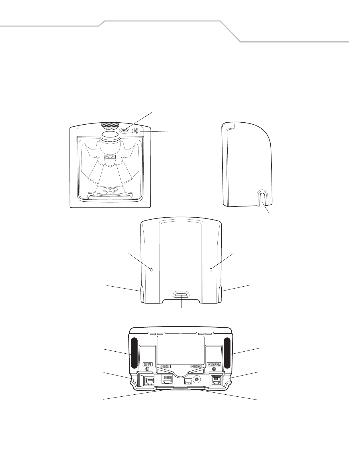
The Symbol LS7708 scanner provides multiple scan patterns that support high throughput applications at the point of sale (POS). The
rastering, 120-line, omni-directional scan pattern provides fast, intuitive, hands-free scanning. The scanner reads all retail
symbologies and has multi-interface capability to interface to all popular POS devices. The scanner mounts on a counter top or vertical
surface such as a wall.
LED Volume Control & Wakeup Button
Speaker
Cable Release Hole
Channel for
Outgoing Cables
Rubber Foot
Channel for
Outgoing Cables
Channel for Outgoing Cables
Cable Release Hole
Channel for
Outgoing Cables
Mounting Bracket Slot
Rubber Foot
Channel for
Outgoing Cables
Channel for
Outgoing Cables
Mounting Bracket Slot
Figure 1-1. Symbol LS7708 Scanner Views
Channel for
Outgoing Cables
Page 22

Symbol LS7708 Product Reference Guide1-4
The Symbol LS7708 scanner supports the following interfaces:
• TTL-level RS-232 connection to a host. Set up communication between the scanner and the host either by scanning bar code
menus or using the Windows-based programming tool 123Scan.
• Keyboard Wedge connection to a host. The host interprets scanned data as keystrokes.
International keyboards supported:
• Windows™ environment: North American, German, French, Spanish, Italian, Swedish, UK English, Brazilian/Portuguese,
and Japanese.
• Windows XP/2000™ environment: French Canadian
• Windows 95/98 environment: French Canadian
• Connection to IBM 468X/469X hosts. Set up communication between the scanner and the IBM terminal either by scanning
bar code menus or using the Windows-based programming tool 123Scan.
• USB connection to a host. The scanner autodetects a USB host and defaults to the HID keyboard interface type. To select
other USB interface types, scan programming bar code menus or use the Windows-based programming tool 123Scan.
• International Keyboards supported (for Windows™ environment): North America, German, French, French International,
Spanish, Italian, Swedish, British, and Japanese.
• Synapse capability that allows the scanner to connect to a wide variety of host systems using a Synapse and Synapse
adapter cable. The scanner autodetects Synapse.
Unpacking the Scanner
Remove the scanner from its packing and inspect it for damage. The following items are included in the package:
• Scanner
• Mounting bracket and hardware
• LS7708 Quick Reference Guide (p/n 72-69530-xx)
• CD containing 123Scan software and Symbol LS7708 Product Reference Guide (p/n 72-69531-xx).
The package may also include the following:
• Power supply and cable
• RS-232C host interface cable
• Synapse Adapter and Synapse cable.
Some host terminals (e.g., IBM 46xx Series) supply power to the scanner, so an external power supply is not required. Contact a
Motorola representative for more information.
If any items are missing or damaged, call the Global Customer Interaction Center. See page xvi for contact information. KEEP THE
PACKING. It is the approved shipping container and should be used if it is ever necessary to return the equipment for servicing.
Page 23
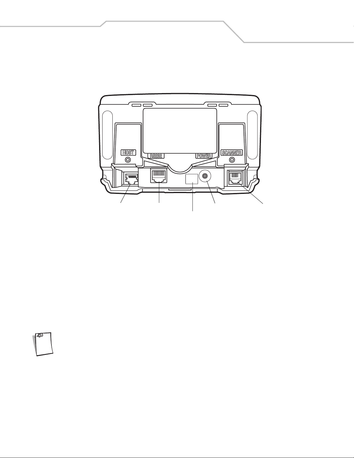
Input/Output Ports
The bottom of the scanner includes the ports in Figure 1-2
Getting Started 1-5
EAS
Host Port
RS-232 Aux Port
EAS Interlock Port (Behind Label)
Power Port
Secondary Scanner
(Synapse) Port
Figure 1-2. Scanner Ports
Power Port. When external power is required, the input to this port is 5V @ 500 mA maximum, 390 mA nominal, with no peripherals,
5V @ 1.5A maximum with peripherals.
Host Port. A 10-pin modular connector. Plug the host cable, the Synapse Adapter cable, or Synapse Power Regulator cable into this
port.
Secondary (Hand-Held) Scanner Port. A 6-pin modular connector. Plug a Synapse-compatible hand-held laser scanner, such
as the Symb ol LS2208, into this port. This scanner can program the Symbol LS7708, and adapts to LS7708 decode parameters
(i.e., code types, lengths, and check digits).
RS-232 Aux Port. A 10-pin modular connector. Use this as an auxiliary port to connect serial devices such as a scale or magstripe
reader. Current draw on this port should not exceed 200 mA. The total current draw on the hand-held port and scanner port should
not exceed 700 mA.
For detailed connection information, see the applicable host chapter.
Note
Page 24

Symbol LS7708 Product Reference Guide1-6
Setting Up the Scanner
Power Options
Depending on the peripherals used, the scanner receives power from one of two sources:
• Via the host through the host cable: If the host can supply 500mA of power, the host cable is less than 8.5’ long, and there
are no peripheral devices in the configuration.
• Via an external power supply: When the host cannot provide sufficient power, the host cable length is more than 8.5’ long,
or a peripheral device is connected to the hand-held and/or scanner ports. The external supply connects directly into the DC
port or through a host cable with an adapter or Y-connection.
When the scanner receives power, the green LED lights and three short high beeps sound, indicating that the scanner is operational.
Connecting the Host and Peripheral Cables
Connect the cables in the following order (see Figure 1-3):
The order of cable insertion is extremely important. Be sure to follow the steps below in order.
CAUTION
1. Plug the host interface cable modular connector into the host port on the scanner.
2. Connect peripheral device cables to the correct ports on the scanner, and the other end of the cables to the peripherals.
3. Connect the external power supply to the host cable, adapter, or power port (if needed, see Power Options).
4. Connect the host cable to the host.
Page 25
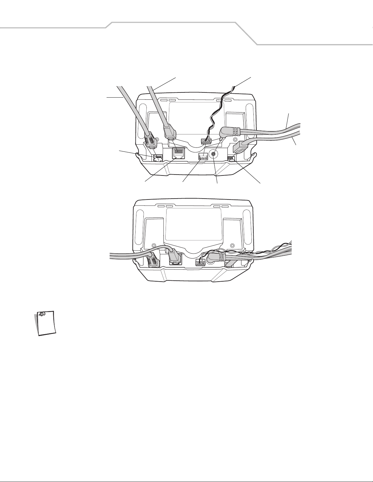
Host
Interface
Cable
Getting Started 1-7
RS-232 Aux Cable EAS Interlock Cable
Power
Cable
Note
Host
EAS Interlock
Power
Secondary Scanner (Synapse)RS-232 Aux
Scanner
Cable
Figure 1-3. Scanner Connections
Different hosts require different cables. The connectors illustrated in each host chapter are examples only.
Connectors may be different from those illustrated, but the steps to connect the scanner are the same.
Page 26
Symbol LS7708 Product Reference Guide1-8
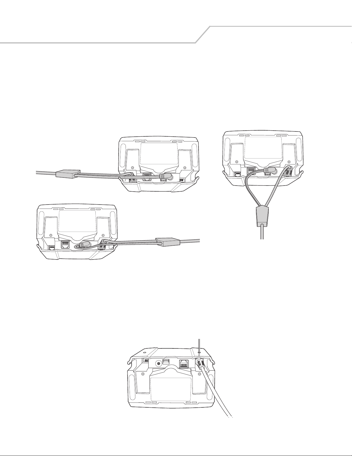
Routing Cables
The scanner case has several channels to route the outgoing cables so that they are organized and don’t hinder the scanner’s
placement (see Figure 1-1 and Figure 1-3). After placing the cable connectors in the appropriate scanner ports, route the cables
through the nearest channel.
For a cable with a Y-connector (containing both power and interface connectors):
1. Connect the power and interface cables to the appropriate ports.
2. Route the cables according to the appropriate diagram in Figure 1-4.
Connections to power and host ports,
side exit: keep power cable straight
and route it ahead with interface cable.
Connections to power and hand-held
scanner ports, side exit: curl power cable
and route it back towards interface cable.
Connections to power and hand-held scanner
ports, back exit: curve power and interface
cables to exit from channels on either side of
the mounting bracket slot.
Figure 1-4. Cable Routing Options
Removing the Host Interface Cable
To remove the host interface cable:
1. Unplug the installed cable’s modular connector by depressing the connector clip and gently pulling back. The two small holes
on the back of the scanner case provide access to the connector clips. (See Figure 1-5.)
2. Follow the steps for Connecting the Host and Peripheral Cables on page 1-6 to connect a new cable.
Figure 1-5. Unplugging the Cable Through the Cable Release Hole
Page 27

Getting Started 1-9
Configuring the Scanner
To configure the scanner, use the bar codes in this manual, or use the 123Scan configuration program.
Refer to Chapter 4, User Preferences for information about programming the scanner using bar code menus. Refer to Chapter 12,
123Scan to configure the scanner using this configuration program. A help file is available in the program.
The scanner supports RS-232, IBM 468X/469X, Keyboard Wedge, USB, and Synapse to interface with a host system. Each hostspecific chapter describes how to set up each of these connections.
Synchronization of Settings
Host Requested Setting Changes
The IBM 4683, IBM Handheld USB, and Synapse hosts can change a limited set of the scanner's settings. The 123Scan host maintains
all the Symbol LS7708 scanner's settings. When a handheld scanner is connected, all setting changes the host requests are
processed by both the LS7708 scanner and the handheld scanner. Only a limited set of handheld scanner settings are updated,
including code type enable/disable, code type lengths, beeper settings, redundancy, and security level settings.
For example, if the IBM 4683 host requests to disable the Code 39 symbology, then Code 39 is disabled on both the LS7708 scanner
and the handheld scanner.
Bar Code Menu Symbols Scanned on the Symbol LS7708 Scanner
A limited set of bar code menu symbols scanned on the Symbol LS7708 scanner are synchronized with the handheld scanner (if
attached). These settings are code type enable/disable, code type lengths, beeper settings, redundancy, and security level settings.
Bar Code Menu Symbols Scanned on the Handheld Scanner
By default, the handheld scanner can program the Symbol LS7708 scanner's settings (primary only mode).
The handheld programming mode setting All Scanners Mode allows programming both the handheld scanner and the Symbol LS7708
scanner simultaneously. In this mode, scanning Set Defaults returns the LS7708 scanner to the default mode.
Another setting isolates the handheld scanner so that the bar code menu symbols scanned apply only to the handheld scanner. To
return to the default functionality change the setting on the Symbol LS7708 scanner directly.
Regardless of the handheld scanner mode, all parameter changes requested by the host and via bar code menu settings on the Symbol
LS7708 scanner are synchronized on the handheld scanner for applicable settings.
Page 28
Symbol LS7708 Product Reference Guide1-10
Mounting the Scanner to a Surface
The Symbol LS7708 is designed to sit on top of a counter or be mounted to a wall. The back of the scanner has a slot that accepts a
mounting bracket to secure it to the mounting surface. The bracket accommodates either mounting option and, once attached to the
scanner, keeps all cables securely in place.
Attaching the Mounting Bracket
Before attaching the scanner to the mounting bracket, remove the oval-shaped rubber feet on the bottom of
Note
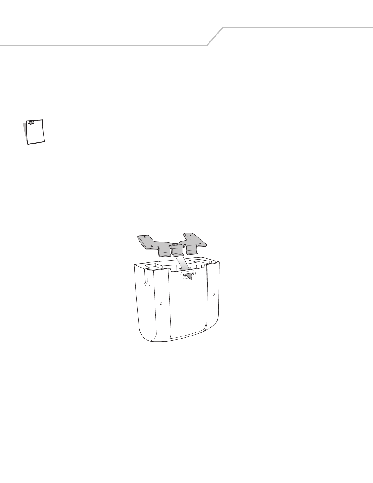
Freestanding Configuration
To set the scanner for freestanding configuration:
1. Connect all interface and power cables to the scanner (see Figure 1-3 on page 1-7). Route the cables appropriately for the
2. Turn the scanner so its bottom is facing up and the connections are visible.
3. Orient the mounting bracket so that the plastic tab is facing down and toward the slot on the back of the scanner, and the
the scanner.
mounting and cable configuration (see Figure 1-4).
square cushion on the mounting bracket is above the power cable.
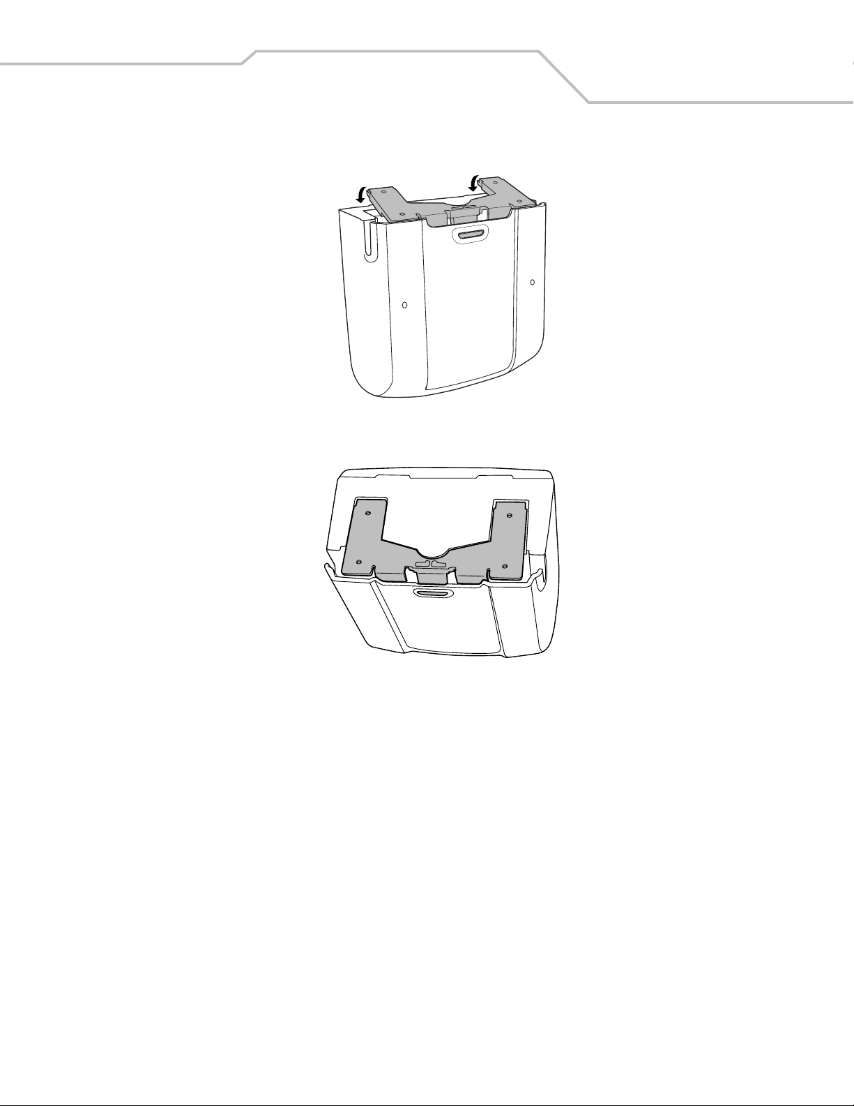
4. Tilt the plastic tab into the slot on the scanner, and rotate the opposite edge downward. As the bracket rotates, push it
toward the slot so that the feet of the bracket lie flat against the scanner’s bottom.
Page 29
Getting Started 1-11
5. When the bracket is flat against the scanner bottom, release pressure so that the feet slide forward into the front of the
scanner.
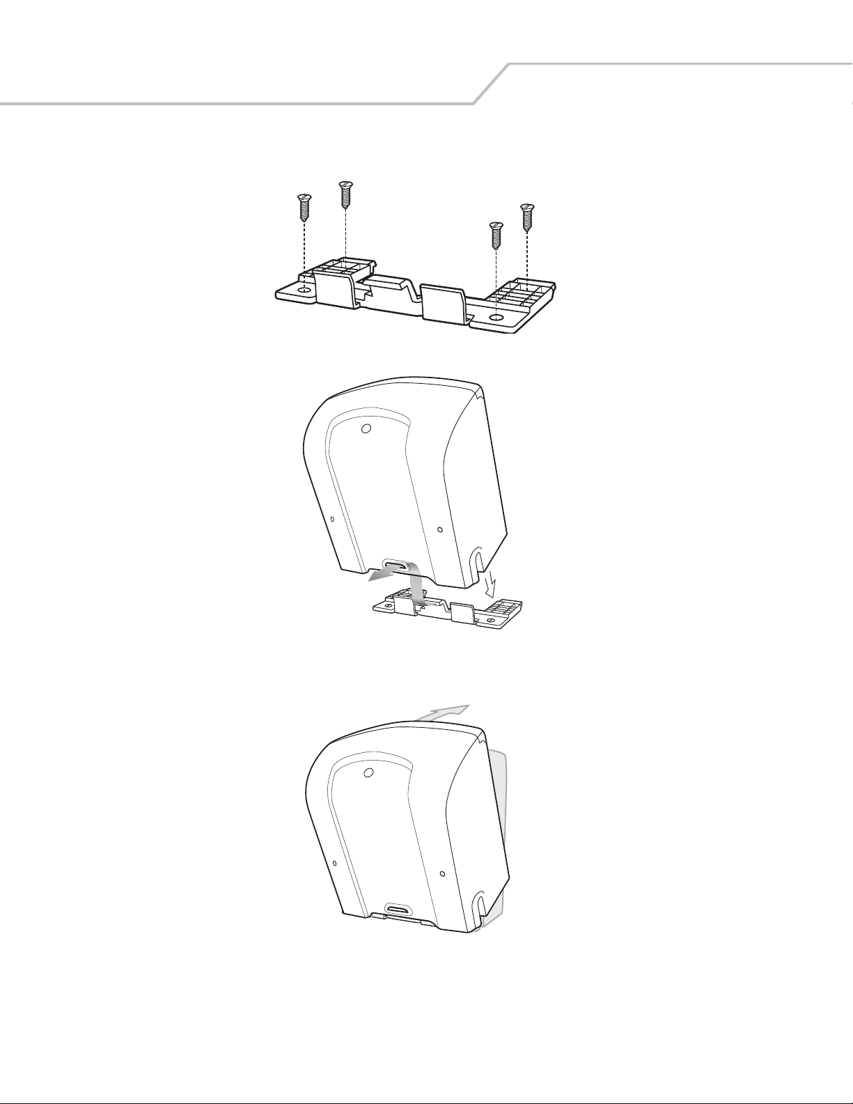
Attached Configuration
To attach the scanner to a mounting surface:
1. Determine the location for mounting the scanner.
2. Remove the square rubber feet that cover the screw holes on the mounting bracket.
3. Remove the two oblong-shaped bumpers on the scanner.
4. Use a pencil to mark the position of the mounting holes. (A mounting template is provided on page E-3 in Appendix E,
Mounting Template.)
5. Place the mounting bracket in position over the drilled holes with its flat surface facing the mounting surface.
Page 30
Symbol LS7708 Product Reference Guide1-12
6. Insert screws through the holes and fasten to the mounting surface.
7. Align the slot at the back of the scanner with the plastic tab on the mounting bracket.
8. Angle the scanner slightly to allow the bracket hook to slide into the slot.
9. Push the scanner towards the plastic tab on the mounting bracket and rotate it so that it is perpendicular to the mounting
surface.
10. Release pressure on the scanner. The bracket locks into place.
Page 31

Detaching the Scanner from the Mounting Bracket
To detach the scanner:
1. Grasp the scanner firmly on both sides.
2. Squeeze the back of the scanner slightly while pushing the scanner in the direction of the slot on the back.
3. Rotate the front of the scanner away from the mounting bracket until the bracket pops out of the slot.
Getting Started 1-13
Page 32

Symbol LS7708 Product Reference Guide1-14
Page 33

Scanning
Introduction . . . . . . . . . . . . . . . . . . . . . . . . . . . . . . . . . . . . . . . . . . . . . . . . . . . . . . . . . . . . . . . . . . . . . . . . . . . . 2-3
Active Scan Area . . . . . . . . . . . . . . . . . . . . . . . . . . . . . . . . . . . . . . . . . . . . . . . . . . . . . . . . . . . . . . . . . . . . . . . . .2-3
Scanning Bar Codes . . . . . . . . . . . . . . . . . . . . . . . . . . . . . . . . . . . . . . . . . . . . . . . . . . . . . . . . . . . . . . . . . . . . . . .2-3
Beeper Definitions . . . . . . . . . . . . . . . . . . . . . . . . . . . . . . . . . . . . . . . . . . . . . . . . . . . . . . . . . . . . . . . . . . . . . . . .2-5
Selecting Beeper Volume. . . . . . . . . . . . . . . . . . . . . . . . . . . . . . . . . . . . . . . . . . . . . . . . . . . . . . . . . . . . . . . . . . .2-6
Sleep Mode . . . . . . . . . . . . . . . . . . . . . . . . . . . . . . . . . . . . . . . . . . . . . . . . . . . . . . . . . . . . . . . . . . . . . . . . . . . . .2-6
LED Definitions. . . . . . . . . . . . . . . . . . . . . . . . . . . . . . . . . . . . . . . . . . . . . . . . . . . . . . . . . . . . . . . . . . . . . . . . . . .2-6
Decode Zone. . . . . . . . . . . . . . . . . . . . . . . . . . . . . . . . . . . . . . . . . . . . . . . . . . . . . . . . . . . . . . . . . . . . . . . . . . . . .2-7
Integrated Electronic Article Surveillance (EAS) . . . . . . . . . . . . . . . . . . . . . . . . . . . . . . . . . . . . . . . . . . . . . . . . .2-8
LS7708 Interlock Cable and EAS . . . . . . . . . . . . . . . . . . . . . . . . . . . . . . . . . . . . . . . . . . . . . . . . . . . . . . . . . 2-8
Installing the Electronic Article Surveillance (EAS) . . . . . . . . . . . . . . . . . . . . . . . . . . . . . . . . . . . . . . . . . . . . . . . 2-8
CheckPoint EAS Model Compatibility . . . . . . . . . . . . . . . . . . . . . . . . . . . . . . . . . . . . . . . . . . . . . . . . . . . . . 2-8
Considerations . . . . . . . . . . . . . . . . . . . . . . . . . . . . . . . . . . . . . . . . . . . . . . . . . . . . . . . . . . . . . . . . . . . . . . .2-8
CheckPoint Contact Information . . . . . . . . . . . . . . . . . . . . . . . . . . . . . . . . . . . . . . . . . . . . . . . . . . . . . . . . .2-8
Deactivation for Sensormatic EAS System . . . . . . . . . . . . . . . . . . . . . . . . . . . . . . . . . . . . . . . . . . . . . . . . . 2-8
Page 34

Symbol LS7708 Product Reference Guide2-2
Page 35

Scanning 2-3
Introduction
This chapter covers the techniques involved in scanning bar codes, beeper and LED definitions, and general instructions and tips about
scanning. Refer to Chapter 1, Getting Started for information on scanner components, and connecting host cables and the power
supply.
Active Scan Area
The active scan area is the area in front of the scanner window in which a bar code can be decoded. The dotted area in Figure 2-1
represents the active scan area for the scanner.
Figure 2-1. Symbol LS7708 Active Scan Area
Scanning Bar Codes
Install and program the scanner. (Refer to each host chapter and Chapter 4, User Preferences, Chapter 13, Symbologies, Chapter 14,
Miscellaneous Scanner Options, and Advanced Data Formatting for instructions on programming the scanner.) For assistance, contact
the local supplier or call the Global Customer Interaction Center. See page xvi for contact information.
For the best scanning performance, the counter top or surface area covered by the active scan area should be a light, solid color. Avoid
designs (e.g., stripes or patterns). A rastering, 120-line, omni-directional scan pattern provides rapid, orientation-free scanning.
To scan a bar code:
1. Ensure all cable connections are secure.
2. Orient the item with the bar code facing the scanner window.
3. Move the item through the active scan area in the direction of the arrows (swipe scanning, see Figure 2-2), or place the item
in front of the scanner (presentation scanning, see Figure 2-3). Ensure that the scan lines cross every bar and space of the
symbol.
Page 36

Symbol LS7708 Product Reference Guide2-4
Figure 2-2. Scanning a Bar Code - Swipe Method
Figure 2-3. Scanning a Bar Code - Presentation Method
4. Upon successful decode, the scanner beeps and the green LED flashes.
For more information on beeper definitions, see Table 2-1.
Page 37

Scanning 2-5
Beeper Definitions
The scanner communicates by emitting different beeper sequences. Table 2-1 defines beeper sequences that occur during normal
scanning and while programming the scanner.
Table 2-1. Standard Beeper Definitions
Beeper Sequence Indication
Standard Use
3 short high beeps Power up.
Short high beep A bar code was decoded (if decode beeper is enabled).
4 long low beeps A transmission error was detected in a scanned symbol. The data is ignored. This occurs if the scanner is not properly
configured. Check option settings.
When scanning bar code menu symbols, indicates the handheld scanner does not support the setting; use the primary
scanner instead.
5 low beeps Conversion or format error.
Lo/hi/lo beep ADF transmit error.
Hi/hi/hi/lo beep RS-232 receive error on RS-232 host or RS-232 auxiliary port.
Parameter Menu Scanning
Short high beep Correct entry scanned or correct menu sequence performed.
Lo/hi beep Input error, incorrect bar code or “Cancel” scanned, wrong entry, incorrect bar code programming sequence;
remain in program mode.
Hi/lo beep Keyboard parameter selected. Enter value using bar code keypad.
Hi/lo/hi/lo beep Successful program exit with change in the parameter setting.
Lo/hi/lo/hi beep Out of host parameter storage space. Scan Set Default Parameter on page 4-5.
Lo/lo/lo/lo beep Unsupported parameter.
Code 39 Buffering
Hi/lo beep New Code 39 data was entered into the buffer.
3 long high beeps Code 39 buffer is full.
Lo/hi/lo beep The Code 39 buffer was erased or there was an attempt to clear or transmit an empty buffer.
Lo/hi beep A successful transmission of buffered data.
Host Specific
USB only
4 short high beeps Scanner has not completed initialization. Wait several seconds and scan again.
Scanner emits a power-up beep
sequence (3 short high beeps) after
scanning a USB Device Type.
This power-up beep occurs more
than once.
Communication with the bus must be established before the scanner can operate at the highest power level.
The USB bus may put the scanner in a state where power to the scanner is cycled on and off more than once. This is
normal and usually happens when the PC cold boots.
RS-232 Host only
1 short high beep A <BEL> character is received and Beep on <BEL> is enabled.
Page 38

Symbol LS7708 Product Reference Guide2-6
Table 2-1. Standard Beeper Definitions
Beeper Sequence Indication
RS-232 Auxiliary Port only
1 short high beep A complete block of data was received and sent to the host, either due to a carriage return or because the two-second
serial response timeout has elapsed.
4 long low beeps A data overrun condition has occurred. Do not scan data from other ports when large amounts of data are sent to the
RS-232 auxiliary port.
Selecting Beeper Volume
The scanner emits a short beep when it successfully reads a bar code. To change the volume of the beep scan the beeper volume bar
code on page 4-7, or use the two-function Volume Control and Wakeup button (see Figure 1-1 on page 1-3) on the front of the scanner
as follows:
1. Press and hold the button for approximately five seconds. The scanner cycles through three settings (low, medium, high)
emitting a two-beep tone at each setting.
2. To select a particular setting, release the button after the desired two-beep tone is heard.
Sleep Mode
The scanner enters Sleep mode when it is inactive for a specified length of time. The scanner has two levels of sleep: laser and motor.
In laser sleep mode, after ten seconds of inactivity the laser pulses at a 50% rate, then drops to 3% after a specified time. In motor
sleep mode, the scanner turns off the motor and the laser.
To wake the scanner from sleep mode, press the Volume Control & Wakeup button (see Figure 1-1). In laser sleep mode, also wake
the scanner by presenting a bar code to the scanner window.
LED Definitions
The scanner also communicates via an LED (see Figure 1-1). Table 2-2 defines LED indications that occur during scanning.
Table 2-2. Standard LED Definitions
LED Indication
Off No power is applied to the scanner.
Green The scanner is on and “ready to scan.”
Momentary green flash A bar code was successfully decoded.
Slow continuous red flashing, green on The scanner is in programming mode.
Fast continuous red flashing, green on There is an internal problem; the laser is shut off for regulatory reasons.
Green on (and laser blinking) Scanner is in Low Power Blink mode.
Red and green on Scanner is in Low Power Motor and Laser Shutdown mode.
Page 39

Decode Zone
Figure 2-4 illustrates the area in which the scanner recognizes bar codes.
Scanning 2-7
Figure 2-4. Symbol LS7708 Decode Zone
Page 40

Symbol LS7708 Product Reference Guide2-8
Integrated Electronic Article Surveillance (EAS)
The scanner includes an Electronic Article Surveillance (EAS) antenna. The scanner and EAS system can operate independently of
each other, or using an exclusive interlock feature. The deactivation range is mapped suitable to the scanning range, so both can be
accomplished almost simultaneously. The interlock feature requires a good decode signal to activate the EAS system.
Do not attempt to activate the interlock feature. Activation instructions are for a Motorola qualified technician
only.
The scanner’s integrated EAS deactivation antenna requires an EAS host cable. This Y-cable connects to the scanner’s host port at
one end, and splits to the host and the EAS system at the other end.
LS7708 Interlock Cable and EAS
To connect the EAS interlock feature to the scanner:
1. Peel off the EAS sticker on the bottom of the scanner (see Figure 1-1 on page 1-3). The sticker covers the EAS interlock port.
2. Plug the EAS interlock cable into the port (see Figure 1-3 on page 1-7).
3. Attach the other end to the EAS system.
Be sure to scan the proper bar code on page 4-17 to activate this feature.
Note
Installing the Electronic Article Surveillance (EAS)
CheckPoint EAS Model Compatibility
The EAS cable is intended for use with CheckPoint CP-VII and CP-IX systems. It does not support CP-IV and other low-power receiverbased EAS deactivation systems.
Considerations
The CheckPoint CP-VII system generates a periodic burst of electromagnetic energy that deactivates EAS tags brought near the
scanner. To avoid interference with the scanner’s operation, take the following precautions when installing the EAS system:
• Position the EAS antenna box as far as possible from the scanner (at least 6 in. / 15.24 cm.)
• Position the EAS antenna, EAS antenna box, EAS control cable, and EAS controller box as far as possible from the scanner’s
host and power cables.
CheckPoint Contact Information
Contact your local Checkpoint representative to install the EAS cable to the Checkpoint Deactivation System.
To contact a representative:
• In the United States call: 800-257-5540 x4300
• Outside the United States: (609) 848-1800 x4300
Deactivation for Sensormatic EAS System
To interface to Sensormatic systems, contact Motorola Product Management.
Page 41

Maintenance and
Technical Specifications
Introduction . . . . . . . . . . . . . . . . . . . . . . . . . . . . . . . . . . . . . . . . . . . . . . . . . . . . . . . . . . . . . . . . . . . . . . . . . . . . 3-3
Maintenance . . . . . . . . . . . . . . . . . . . . . . . . . . . . . . . . . . . . . . . . . . . . . . . . . . . . . . . . . . . . . . . . . . . . . . . . . . . .3-3
Replacing the Scanner Window. . . . . . . . . . . . . . . . . . . . . . . . . . . . . . . . . . . . . . . . . . . . . . . . . . . . . . . . . . . . . .3-4
Troubleshooting . . . . . . . . . . . . . . . . . . . . . . . . . . . . . . . . . . . . . . . . . . . . . . . . . . . . . . . . . . . . . . . . . . . . . . . . . .3-6
Technical Specifications . . . . . . . . . . . . . . . . . . . . . . . . . . . . . . . . . . . . . . . . . . . . . . . . . . . . . . . . . . . . . . . . . . .3-7
Scanner Signal Descriptions . . . . . . . . . . . . . . . . . . . . . . . . . . . . . . . . . . . . . . . . . . . . . . . . . . . . . . . . . . . . . . . . 3-9
Page 42

Symbol LS7708 Product Reference Guide3-2
Page 43

Maintenance and Technical Specifications 3-3
Introduction
This chapter covers suggested scanner maintenance, troubleshooting, technical specifications, and signal descriptions (pinouts).
Maintenance
Cleaning the exit window is the only maintenance required. A dirty window can affect scanning accuracy.
• Do not allow abrasive material to touch the window.
• Remove dirt particles with a damp cloth.
• Wipe the window using a tissue moistened with ammonia/water.
• Do not spray water or other cleaning liquids directly into the window.
Page 44

Symbol LS7708 Product Reference Guide3-4
Replacing the Scanner Window
To replace the scanner window:
1. Reach under the lip of the front panel and lift it away from the scanner.
Front Panel
Figure 3-1. Removing the Front Panel
2. Unfasten the screws behind the panel that secure the window frame.)
Screw
Screw
Figure 3-2. Unfastening the Screws that Secure the Window Frame
3. Tilt the loosened window frame forward far enough to gain access to the exit window.
4. Carefully remove the exit window from the window frame.
Page 45

Glass
Figure 3-3. Removing and Replacing the Window Glass
5. Insert a new, clean exit window.
6. Tilt the window frame back into position.
7. Secure the window frame to the scanner using two screws.
8. Snap the front panel back into position.
Maintenance and Technical Specifications 3-5
Page 46

Symbol LS7708 Product Reference Guide3-6
Troubleshooting
Problem Possible Causes Possible Solutions
The omni-line scan pattern does not
display when following the directions for
installing the host cable on page 1-5.
Scan line(s) display, but bar code cannot
be read.
Bar code is decoded, but not transmitted
to the host.
Scanned data is incorrectly displayed on
the host.
Although the green and red Power LEDs
are on, the scanner does not produce the
omni-directional scan pattern.
USB or Synapse host not functioning
properly.
No power to the scanner. Ensure the host has power and is on. If the scanner uses a separate
power supply, ensure it’s connected to a working AC outlet.
Interface cable is not properly connected. Check for loose cable connections.
Scanner is not programmed to read the bar
code type.
Bar code is damaged. Try scanning other bar codes of the same bar code type.
Bar code is too far from scanner. Move the bar code closer to the scanner.
The host has disabled scanning or
overridden parameter settings.
Scanner is not programmed for the correct
host type.
Scanner is not programmed to work with
the host. Check scanner host type
parameters or editing options.
Scanner has gone into Low Power “Motor
Sleep” Mode.
Scanner does not recognize host. Remove and reinsert external power supply to force cable to autodetect
Ensure scanner is programmed to read the bar code type being scanned.
See the technical person in charge of scanning.
Scan the appropriate host type bar code.
• Ensure proper host is selected.
• For RS-232, ensure the scanner’s communication parameters match
the host’s settings.
• For keyboard wedge, ensure scanner is programmed with the correct
country code and that the CAPS LOCK key is off.
• Ensure editing options (e.g., UPCE-to-UPCA Conversion) are properly
programmed.
Press the Volume Control & Wakeup button to awaken the scanner.
correct host.
An error occurs when connecting to a USB
host.
Handheld scanner does not power on. External power supply is not attached. Connect an external power supply directly to the scanner, not to the host
Auxiliary RS-232 device data is not
received properly.
Cables were installed in the incorrect order. See Connecting the Host and Peripheral Cables on page 1-6 for the
correct order of insertion.
cable.
External power supply is not attached. Connect an external power supply directly to the scanner, not to the host
cable.
Auxiliary device supplies TTL level RS-232
signals.
Auxiliary settings are incorrect. Use auxiliary RS-232 port settings, not the RS-232 host settings.
Use a device that supports standard RS-232 signal levels.
If after performing these checks the symbol still does not scan, contact the distributor or call the Global
Note
Customer Interaction Center. See page xvi for contact information.
Page 47

Technical Specifications
Item Description
Physical Characteristics
Dimensions:
Without stand: Height
Width
Depth
Weight Scanner only: 2.04 lbs. (925 g)
Power Source Power drawn from host terminal or external power supply; depends on host type.
Voltage 5.5 VDC to 4.75 VDC measured at host terminal or external power supply
Current 390mA (nominal) / 500 mA maximum with no peripheral
Power (nominal) 2 watts with no peripheral
Mounting Options Integral mounting bracket
Color Cash Register White or Twilight Black
Performance Characteristics
Light Source 650nm visible laser diode
Maintenance and Technical Specifications 3-7
Table 3-1. Technical Specifications
6.3 in. (16 cm)
5.98 in. (15.2 cm)
3.73 in. (9.5 cm)
Print Contrast 25% minimum reflective difference
Scan Patterns Static: 24 scan lines
Raster: 120 scan lines
Scan Rate Static: 2,400 scans/sec.
Raster: 12,000 scans/sec.
Depth of Field 0-10 in./0-25.4 cm @ 13 mil (100% UPC/EAN)
Typical Working Range 5 mil: (38%) 0.5 to 2.5 in./ 1.27 to 6.4 cm
7.8 mil: (60%) 0 to 5 in./ 0 to 12.7 cm
10.4 mil: (80%) 0 to 7.5 in./ 0 to 19 cm
13 mil: (100%) 0 to 10.0 in./ 0 to 25.4 cm
Minimum Resolution 5 mil
Decode Capability UPC/EAN/JAN, UPC/EAN with Supplementals, UCC/EAN 128, Code 128, ISBT 128, Code 39,
Code 39 Trioptic, Interleaved 2 of 5, Discrete 2 of 5, Code 93, Code 11, Codabar, RSS Variants
Interfaces Supported USB, RS-232, IBM® 468X/9X, Keyboard Wedge, and Synapse™ (allows connectivity to virtually
every POS host type), SPCI (for 123Scan)
User Environment
Operating Temperature 32° to 104°F (0° to 40°C)
Storage Temperature -40° to 140°F (-40° to 60°C)
Humidity 5% to 95% (non-condensing)
Ambient Light Immunity Immune to normal artificial indoor and natural outdoor (direct sunlight) lighting conditions.
Fluorescent, Incandescent, Mercury Vapor and Sodium Vapor: 450 Ft Candles (4,844 Lux)
Sunlight: 8000 Ft Candles (86,111 Lux)
Page 48

Symbol LS7708 Product Reference Guide3-8
Table 3-1. Technical Specifications (Continued)
Item Description
EAS Support Checkpoint Electronic Article Surveillance Antenna (EAS) Included
Sensormatic - Contact Product Management
Regulatory
Electrical Safety Certified to UL60950, CSA C22.2 No.60950, EN60950
Laser Safety CDRH Class IIa Laser Product
IEC 60825 Class 1 Laser Product
EMC CISPRA 22 Class B, FCC Part 15 Class B, EN55024, EN61000-3-2, EN61000-3-3
1
Refers to 100% UPC bar code (80% contrast) located 4 in. (10 cm) from the scanner.
Page 49

Scanner Signal Descriptions
Maintenance and Technical Specifications 3-9
Pin 1
Host
Port
Host
Port
Pin 10
modular connector
RS-232
Aux Port
Pin 1
Interface cable
EAS
Interlock
Port
RS-232
Auxiliary Port
Power
Port
Pin 10
Synapse
Port
Pin 1
Pin 6
Hand-Held
Scanner Port
Figure 3-4. Cable Pinouts
Page 50

Symbol LS7708 Product Reference Guide3-10
The signal descriptions in Table 3-2 apply to the connector on the scanner and are for reference only.
Table 3-2. Scanner/Host Signal Pin-outs
Symbol LS7708
Keyboard
Pin IBM Synapse RS-232
1 Reserved SynClock Reserved Reserved Jump to Pin 6 Reserved
2 Power Power Power Power Power Power
3 Ground Ground Ground Ground Ground Ground
4 IBM_A(+) Reserved TxD KeyClock Reserved TxD
5 Reserved Reserved RxD TermData D + Reserved
6 IBM_B(-) SynData RTS KeyData Jump to Pin 1 RxD
7 Reserved Reserved CTS TermClock D - Reserved
8 Reserved Reserved Reserved Reserved Reserved Reserved
9 Reserved Reserved Reserved Reserved Reserved Reserved
10 Reserved Reserved Reserved Reserved Reserved Reserved
Wedge USB Download
Table 3-3. RS-232 Auxiliary Port Pinouts
Pin # Signal Unterminated Wire* Description
1-
2 DTR Brown Output, Data Terminal Ready
3 RXD Orange Input, Received Data
4 VCC Red 5 volts
5 RTS Green Output, Ready to Send
6 GND Black Ground
7 CTS Purple Input, Clear to Send
8-
9 TXD Yellow Output, Transmitted Data
10 -
*The RS-232 port can power a connected device, such as a scale, magstripe reader, or hand-held scanner. The
device’s mating connector is wired to the end of an unterminated cable. Contact the Global Customer
Interaction Center to obtain an unterminated cable for this port. The following table lists unterminated wires
and their functions.
If the device attached to the RS-232 Auxiliary Port is self-powered, do not connect the red wire (VCC) to the
mating connector. This prevents the device from back-powering the LS7708.
Page 51

Maintenance and Technical Specifications 3-11
Table 3-4. Hand-Held Scanner Port Pinouts
Pin 1 Pin 2Pin 3Pin 4Pin 5Pin 6
SYNDATA SYNCLK VCC GND - -
Table 3-5. EAS Interlock Port Pinouts
Pin 1Pin 2Pin 3Pin 4
VCC GND - INTERLOCK
Page 52

Symbol LS7708 Product Reference Guide3-12
Page 53

User Preferences
Introduction . . . . . . . . . . . . . . . . . . . . . . . . . . . . . . . . . . . . . . . . . . . . . . . . . . . . . . . . . . . . . . . . . . . . . . . . . . . . 4-3
Scanning Sequence Examples . . . . . . . . . . . . . . . . . . . . . . . . . . . . . . . . . . . . . . . . . . . . . . . . . . . . . . . . . . . . . . .4-3
Errors While Scanning . . . . . . . . . . . . . . . . . . . . . . . . . . . . . . . . . . . . . . . . . . . . . . . . . . . . . . . . . . . . . . . . . . . . .4-3
User Preferences Default Parameters . . . . . . . . . . . . . . . . . . . . . . . . . . . . . . . . . . . . . . . . . . . . . . . . . . . . . . . . .4-3
User Preferences . . . . . . . . . . . . . . . . . . . . . . . . . . . . . . . . . . . . . . . . . . . . . . . . . . . . . . . . . . . . . . . . . . . . . . . . . 4-5
Set Default Parameter . . . . . . . . . . . . . . . . . . . . . . . . . . . . . . . . . . . . . . . . . . . . . . . . . . . . . . . . . . . . . . . . .4-5
Beeper Tone . . . . . . . . . . . . . . . . . . . . . . . . . . . . . . . . . . . . . . . . . . . . . . . . . . . . . . . . . . . . . . . . . . . . . . . . .4-5
Beeper Volume. . . . . . . . . . . . . . . . . . . . . . . . . . . . . . . . . . . . . . . . . . . . . . . . . . . . . . . . . . . . . . . . . . . . . . . 4-7
Beep After Good Decode . . . . . . . . . . . . . . . . . . . . . . . . . . . . . . . . . . . . . . . . . . . . . . . . . . . . . . . . . . . . . . .4-9
Low Power Mode . . . . . . . . . . . . . . . . . . . . . . . . . . . . . . . . . . . . . . . . . . . . . . . . . . . . . . . . . . . . . . . . . . . .4-10
Scan Pattern Mode. . . . . . . . . . . . . . . . . . . . . . . . . . . . . . . . . . . . . . . . . . . . . . . . . . . . . . . . . . . . . . . . . . .4-11
Timeout Between Decodes . . . . . . . . . . . . . . . . . . . . . . . . . . . . . . . . . . . . . . . . . . . . . . . . . . . . . . . . . . . . 4-12
Time Delay to Low Power Mode . . . . . . . . . . . . . . . . . . . . . . . . . . . . . . . . . . . . . . . . . . . . . . . . . . . . . . . . 4-13
Linear UPC/EAN Decode . . . . . . . . . . . . . . . . . . . . . . . . . . . . . . . . . . . . . . . . . . . . . . . . . . . . . . . . . . . . . .4-15
UPC Half Block Stitching . . . . . . . . . . . . . . . . . . . . . . . . . . . . . . . . . . . . . . . . . . . . . . . . . . . . . . . . . . . . . . 4-16
EAS Interlock . . . . . . . . . . . . . . . . . . . . . . . . . . . . . . . . . . . . . . . . . . . . . . . . . . . . . . . . . . . . . . . . . . . . . . . 4-17
Page 54

Symbol LSSymbol LS7708 Product Reference Guide4-2
Page 55

User Preferences 4-3
Introduction
The scanner can be programmed to perform various functions or activate different features. This chapter describes each user
preference feature and provides the programming bar codes necessary for selecting these features for the scanner. Before
programming, follow the instructions in Chapter 1, Getting Started.
The scanner is shipped with the settings shown in the User Preferences Default Table on page 4-4 (also see Appendix A, Standard
Default Parameters for all host device and miscellaneous scanner defaults).
To set feature values scan single bar codes or short bar code sequences. The settings are stored in non-volatile memory and are
preserved even when the scanner is powered down. Scanning parameter setting bar codes with the primary scanner also changes
settings on the auxiliary scanner.
If not using a Synapse or USB cable, select a host type (see the host chapter) after the power-up beeps. This only needs to be done
once upon the first power-up when connected to a new host.
To return all features to their default values, scan the Set All Defaults bar code on page 4-5. Throughout the programming bar code
menus, asterisks (
*) indicate default values.
* Indicates Default
*High Beeper Frequency
Feature/Option
Scanning Sequence Examples
In most cases scanning only one bar code sets a specific parameter value. For example, to set the beeper tone to high, scan the High
Frequency (beeper tone) bar code listed under Beeper Tone on page 4-5. The scanner issues a short high beep and the LED turns green,
signifying a successful parameter entry.
Other parameters, such as Serial Response Time-Out or setting Data Transmission Formats, require scanning several bar codes. Refer
to Host Serial Response Time-out on page 6-26 and Scan Data Options on page 14-7 for descriptions of this procedure.
Errors While Scanning
Unless otherwise specified, if an error occurs during a scanning sequence, just re-scan the correct parameter.
User Preferences Default Parameters
Table 4-1 lists the defaults for user preferences parameters. To change any option, scan the appropriate bar code(s) beginning in User
Preferences on page 4-5.
Refer to Appendix A, Standard Default Parameters for all user preferences, hosts, symbologies, and
Note
miscellaneous default parameters.
Page 56

Symbol LSSymbol LS7708 Product Reference Guide4-4
Table 4-1. User Preferences Default Table
Parameter Default Page Number
User Preferences
Set Default Parameter All Defaults 4-5
Beeper Tone Medium 4-5
Beeper Volume High 4-7
Beep After Good Decode Enable 4-9
Low Power Mode Low Power Blink Mode 4-10
Scan Pattern Mode Rastering 4-11
Time-out Between Same Symbol 0.6 sec 4-12
Time-out Between Different Symbols 0.2 sec 4-12
Time Delay to Low Power Mode 30 Minutes 4-13
Linear UPC/EAN Decode Disable 4-15
UPC Half Block Stitching Enable 4-16
EAS Interlock Disable 4-17
Page 57

User Preferences
Scanning parameter setting bar codes with the primary scanner also changes settings on the auxiliary
Note
Set Default Parameter
Scanning this bar code returns all parameters to the default values listed in Table A-1 on page A-1.
scanner.
Set All Defaults
User Preferences 4-5
Beeper Tone
To select a decode beep frequency (tone), scan the Low Frequency, Medium Frequency, or High Frequency bar codes.
Low Frequency
Page 58

Symbol LSSymbol LS7708 Product Reference Guide4-6
Beeper Tone (continued)
*
Medium Frequency
High Frequency
Page 59

Beeper Volume
To select a beeper volume, scan one of the following bar codes.
Low Beeper Volume
Low Beeper Volume
User Preferences 4-7
Medium Beeper Volume
Medium Beeper Volume
Page 60

Symbol LSSymbol LS7708 Product Reference Guide4-8
High Beeper Volume
High Beeper Volume
Page 61

User Preferences 4-9
Beep After Good Decode
Scan a bar code below to select whether or not the scanner beeps after a good decode. If Do Not Beep After Good Decode is
selected, the beeper still operates during parameter menu scanning and indicates error conditions.
*Beep After Good Decode
(Enable)
Do Not Beep After Good Decode
(Disable)
Page 62

Symbol LSSymbol LS7708 Product Reference Guide4-10
Low Power Mode
After a period of inactivity, the scanner enters a reduced power mode. This parameter controls how aggressively power is conserved,
and therefore determines the method of waking the scanner up.
Low Power Blink
Selecting Low Power Blink Mode causes the scanner (after a period of inactivity) to blink the laser infrequently to save power. The
green LED remains lit. To restore the scanner to full power mode, present a bar code.
*Low Power Blink Mode
Motor and Laser Shut Down
Selecting Motor and Laser Shut Down causes the scanner (after a period of inactivity) to turn off the motor and laser. The red and
green LEDs remain lit. Depress the Volume Control and Wakeup button (see Figure 1-1 on page 1-3) to awaken the scanner to its full
power mode.
Low Power Motor and Laser Shut Down
Page 63

User Preferences 4-11
Scan Pattern Mode
The Symbol LS7708 has a very aggressive scan pattern that is both omnidirectional and raster. To select a static omnidirectional
pattern, scan the Omnidirectional Pattern bar code to change the scan pattern.
*Rastering Omnidirectional Pattern
Omnidirectional Pattern
Page 64

Symbol LSSymbol LS7708 Product Reference Guide4-12
Timeout Between Decodes
Timeout Between Decodes, Same Symbol
This parameter sets the minimum time between decodes of the same symbol. It is programmable in 0.1-second increments from 0.0
to 9.9 seconds. Setting this above 0.4 seconds is recommended. The default for this parameter is 0.6 seconds.
Scan the bar code below to select a new timeout. Next, scan two numeric bar codes beginning in Numeric Bar Codes on page D-1
that correspond to the desired timeout. Include a leading zero for single digit numbers. For example, to set a timeout of 0.5 seconds,
scan the bar code below, then scan the “0” and “5” bar codes. If an error occurs, or to change the selection, scan Cancel on page D-8.
Timeout Between Same Symbol
Timeout Between Decodes, Different Symbol
This parameter sets the minimum time between decodes of different symbols. It is programmable in 0.1-second increments from 0.0
to 9.9 seconds. The default for this parameter is 0.2 seconds.
Scan the bar code below to select a new timeout. Next, scan two numeric bar codes beginning in Numeric Bar Codes on page D-1
that correspond to the desired timeout. Include a leading zero for single digit numbers. For example, to set a timeout of 0.5 seconds,
scan the bar code below, then scan the “0” and “5” bar codes. If an error occurs, or to change the selection, scan Cancel on page D-8.
Timeout Between Different Symbol
Page 65

User Preferences 4-13
Time Delay to Low Power Mode
This parameter sets the time that the scanner remains active after any scanning activity. Depending on the selection, the scanner
enters a sleep mode 15, 30, 60, or 90 minutes after the last attempted decode. To awaken the scanner, see Low Power Mode on page
4-10.
15 Minutes
*30 Minutes
Page 66

Symbol LSSymbol LS7708 Product Reference Guide4-14
Time Delay to Low Power Mode (continued)
60 Minutes
90 Minutes
Page 67

User Preferences 4-15
Linear UPC/EAN Decode
This option applies to code types containing two adjacent blocks (e.g., UPC-A, EAN-8, EAN-13). When enabled, a bar code is
transmitted only when both the left and right blocks are successfully decoded within one laser scan. Enable this option when bar
codes are in proximity to each other.
Enable Linear UPC/EAN Decode
*Disable Linear UPC/EAN Decode
Page 68

Symbol LSSymbol LS7708 Product Reference Guide4-16
UPC Half Block Stitching
This parameter enables UPC Half Block Stitching for the Symbol LS7708 omnidirectional scanner only.
*Enable UPC Half Block Stitching
Disable UPC Half Block Stitching
Page 69

EAS Interlock
Enable EAS Interlock
When enabled, the EAS tag is de-activated only when the associated bar code is decoded.
Enable EAS Interlock
User Preferences 4-17
Disable EAS Interlock
When disabled (default), the EAS tag is de-activated independently of any bar code scanning.
*Disable EAS Interlock
Page 70

Symbol LSSymbol LS7708 Product Reference Guide4-18
Page 71

Keyboard Wedge Interface
Introduction . . . . . . . . . . . . . . . . . . . . . . . . . . . . . . . . . . . . . . . . . . . . . . . . . . . . . . . . . . . . . . . . . . . . . . . . . . . . 5-3
Connecting a Keyboard Wedge Interface . . . . . . . . . . . . . . . . . . . . . . . . . . . . . . . . . . . . . . . . . . . . . . . . . . . . . . 5-4
Keyboard Wedge Default Parameters . . . . . . . . . . . . . . . . . . . . . . . . . . . . . . . . . . . . . . . . . . . . . . . . . . . . . . . . .5-6
Keyboard Wedge Host Types. . . . . . . . . . . . . . . . . . . . . . . . . . . . . . . . . . . . . . . . . . . . . . . . . . . . . . . . . . . . 5-7
Keyboard Wedge Country Types (Country Codes) . . . . . . . . . . . . . . . . . . . . . . . . . . . . . . . . . . . . . . . . . . . .5-9
Ignore Unknown Characters. . . . . . . . . . . . . . . . . . . . . . . . . . . . . . . . . . . . . . . . . . . . . . . . . . . . . . . . . . . . 5-14
Keystroke Delay . . . . . . . . . . . . . . . . . . . . . . . . . . . . . . . . . . . . . . . . . . . . . . . . . . . . . . . . . . . . . . . . . . . . .5-15
Intra-Keystroke Delay. . . . . . . . . . . . . . . . . . . . . . . . . . . . . . . . . . . . . . . . . . . . . . . . . . . . . . . . . . . . . . . . . 5-17
Alternate Numeric Keypad Emulation . . . . . . . . . . . . . . . . . . . . . . . . . . . . . . . . . . . . . . . . . . . . . . . . . . . .5-18
Caps Lock On . . . . . . . . . . . . . . . . . . . . . . . . . . . . . . . . . . . . . . . . . . . . . . . . . . . . . . . . . . . . . . . . . . . . . . . 5-19
Caps Lock Override. . . . . . . . . . . . . . . . . . . . . . . . . . . . . . . . . . . . . . . . . . . . . . . . . . . . . . . . . . . . . . . . . . . 5-20
Convert Wedge Data . . . . . . . . . . . . . . . . . . . . . . . . . . . . . . . . . . . . . . . . . . . . . . . . . . . . . . . . . . . . . . . . . 5-21
Function Key Mapping . . . . . . . . . . . . . . . . . . . . . . . . . . . . . . . . . . . . . . . . . . . . . . . . . . . . . . . . . . . . . . . .5-23
FN1 Substitution. . . . . . . . . . . . . . . . . . . . . . . . . . . . . . . . . . . . . . . . . . . . . . . . . . . . . . . . . . . . . . . . . . . . .5-24
Send Make Break. . . . . . . . . . . . . . . . . . . . . . . . . . . . . . . . . . . . . . . . . . . . . . . . . . . . . . . . . . . . . . . . . . . .5-25
OnKeyboard Maps . . . . . . . . . . . . . . . . . . . . . . . . . . . . . . . . . . . . . . . . . . . . . . . . . . . . . . . . . . . . . . . . . . . 5-26
ASCII Character Set . . . . . . . . . . . . . . . . . . . . . . . . . . . . . . . . . . . . . . . . . . . . . . . . . . . . . . . . . . . . . . . . . . . . . .5-28
Page 72

Symbol LS7708 Product Reference Guide5-2
Page 73

Keyboard Wedge Interface 5-3
Introduction
This chapter provides information for setting up the scanner with a Keyboard Wedge interface. Use this interface type to attach the
scanner between the keyboard and host computer. The scanner translates bar code data into keystrokes which the host computer
accepts as if they originate from the keyboard.
This mode of operation allows adding bar code reading functionality to a system designed for manual keyboard input. In this mode
the keyboard keystrokes are simply passed through.
Throughout the programming bar code menus, asterisks (
* Indicates Default
*) indicate default values.
*North American
Feature/Option
Page 74

Symbol LS7708 Product Reference Guide5-4
Connecting a Keyboard Wedge Interface
To connect the Keyboard Wedge configuration (see Figure 5-1):
Host Port
Keyboard
Power Port
Host
Keyboard Port
Figure 5-1. Keyboard Wedge Connection Without Peripherals - Power Supplied Externally
1. Switch off the host and unplug the keyboard connector.
2. Attach the modular connector of the Y-cable to the host port on the scanner.
3. Connect the round male DIN host connector of the Y-cable to the keyboard port on the host.
4. Connect the round female DIN keyboard connector of the Y-cable to the keyboard connector.
5. Connect the peripherals, if any, to their respective ports (see Figure 5-2).
6. Connect the power supply to the scanner’s power port.
7. Ensure that all connections are secure.
8. Turn on the host system.
9. Scan the appropriate bar codes in this chapter or use 123Scan to configure the scanner.
Interface cables vary depending on configuration. The connectors may be different from the examples
illustrated, but the steps to connect the scanner are the same. See Chapter 1, Getting Started for connection
information.
Page 75

Keyboard Wedge Interface 5-5
Keyboard
Host
RS-232 Auxiliary Device
Hand-Held Scanner
Host Port
Power Port
Power Supply
Figure 5-2. Keyboard Wedge Connection with Peripherals - Power Supplied Externally
Page 76

Symbol LS7708 Product Reference Guide5-6
Keyboard Wedge Default Parameters
Table 5-1 lists the defaults for Keyboard Wedge host parameters. To change any option, scan the appropriate bar code(s) beginning
in Keyboard Wedge Host Types on page 5-7.
Scanning parameter setting bar codes with the primary scanner also changes settings on the auxiliary
Note
Note
scanner.
See Appendix A, Standard Default Parameters for all user preferences, hosts, symbologies, and
miscellaneous default parameters.
Table 5-1. Keyboard Wedge Host Default Table
Parameter Default
Keyboard Wedge Host Parameters
Number
Page
Keyboard Wedge Host Type IBM PC/AT & IBM PC Compatibles
Country Types (Country Codes) North American 5-9
Ignore Unknown Characters Send Bar Codes 5-14
Keystroke Delay No Delay 5-15
Intra-Keystroke Delay Disable 5-17
Alternate Numeric Keypad Emulation Disable 5-18
Caps Lock On Disable 5-19
Caps Lock Override Disable 5-20
Convert Wedge Data No Convert 5-21
Function Key Mapping Disable 5-23
FN1 Substitution Disable 5-24
Send Make Break Disable 5-25
1
User selection is required to configure this interface and this is the most common selection.
1
5-7
Page 77

Keyboard Wedge Host Types
Select the keyboard wedge host by scanning one of the following bar codes.
Keyboard Wedge Interface 5-7
IBM PC/AT & IBM PC Compatibles
1
Note
IBM PS/2 (Model 30)
1
User selection is required to configure this interface and this is the most common selection.
Page 78

Symbol LS7708 Product Reference Guide5-8
Keyboard Wedge Host Types (continued)
IBM AT NOTEBOOK
NCR 7052
Page 79

Keyboard Wedge Interface 5-9
Keyboard Wedge Country Types (Country Codes)
Scan the bar code corresponding to the keyboard type. If the particular keyboard type is not listed, see Alternate Numeric Keypad
Emulation on page 5-18.
*North American
German Windows
Page 80

Symbol LS7708 Product Reference Guide5-10
Keyboard Wedge Country Types (continued)
French Windows
French Canadian Win 95/98
Page 81

Keyboard Wedge Country Types (continued)
French Canadian Windows XP/2000
Keyboard Wedge Interface 5-11
Spanish Windows
Page 82

Symbol LS7708 Product Reference Guide5-12
Keyboard Wedge Country Types (continued)
Italian Windows
Swedish Windows
Page 83

Keyboard Wedge Country Types (continued)
UK English Windows
Keyboard Wedge Interface 5-13
Japanese Windows
Page 84

Symbol LS7708 Product Reference Guide5-14
Keyboard Wedge Country Types (continued)
Brazilian/Portuguese Windows
Ignore Unknown Characters
Unknown characters are characters the host does not recognize. When Send Bar Codes With Unknown Characters is selected,
all bar code data is sent except for unknown characters, and no error beeps sound on the scanner. When Do Not Send Bar Codes
With Unknown Characters is selected, bar code data is sent up to the first unknown character and then four (error) beeps sound
on the scanner.
*Send Bar Codes With Unknown Characters
Page 85

Ignore Unknown Characters (continued)
Do Not Send Bar Codes With Unknown Characters
Keyboard Wedge Interface 5-15
Keystroke Delay
This is the delay in milliseconds between emulated keystrokes. Scan a bar code below to increase the delay when hosts require a
slower transmission of data.
*No Delay
Page 86

Symbol LS7708 Product Reference Guide5-16
Keystroke Delay (continued)
Medium Delay (20 msec)
Long Delay (40 msec)
Page 87

Keyboard Wedge Interface 5-17
Intra-Keystroke Delay
Enable this to insert an additional delay between each emulated key depression and release. This sets the Keystroke Delay parameter
to a minimum of 5 msec as well.
Enable
*Disable
Page 88

Symbol LS7708 Product Reference Guide5-18
Alternate Numeric Keypad Emulation
This allows emulation of most other country keyboard types not listed in Keyboard Wedge Country Types (Country Codes) on page 5-
9 in a Microsoft operating system environment.
Enable Alternate Numeric Keypad
*Disable Alternate Numeric Keypad
Page 89

Caps Lock On
When enabled, the scanner emulates keystrokes as if the Caps Lock key is always pressed.
Enable Caps Lock On
Keyboard Wedge Interface 5-19
*Disable Caps Lock On
Page 90

Symbol LS7708 Product Reference Guide5-20
Caps Lock Override
When enabled, on AT or AT Notebook hosts, the keyboard ignores the state of the Caps Lock key. Therefore, an ‘A’ in the bar code is
sent as an ‘A’ regardless of the state of the keyboard’s Caps Lock key.
Enable Caps Lock Override
Note
*Disable Caps Lock Override
If both Caps Lock On and Caps Lock Override are enabled, Caps Lock Override takes precedence.
Page 91

Convert Wedge Data
When enabled, the scanner converts all bar code data to the selected case.
Convert to Upper Case
Keyboard Wedge Interface 5-21
Convert to Lower Case
Page 92

Symbol LS7708 Product Reference Guide5-22
Convert Wedge Data (continued)
*
No Convert
Page 93

Keyboard Wedge Interface 5-23
Function Key Mapping
ASCII values under 32 are normally sent as a control-key sequences (see Table 7-2 on page 7-24). Enable this parameter to send the
keys in bold in place of the standard key mapping. Items that do not have a bold entry remain the same whether or not this parameter
is enabled.
Enable
*Disable
Page 94

Symbol LS7708 Product Reference Guide5-24
FN1 Substitution
Enable this to replace any FN1 characters in an EAN 128 bar code with a selected Key Category and Key Value (see FN1 Substitution
Values on page 14-6).
Enable
*Disable
Page 95

Send Make Break
When enabled, the scan codes for releasing a key are not sent.
*Send Make and Break Scan Codes
Keyboard Wedge Interface 5-25
Send Make Scan Code Only
Page 96

Symbol LS7708 Product Reference Guide5-26
OnKeyboard Maps
The following keyboard maps are provided for prefix/suffix keystroke parameters. To program the prefix/suffix values, see the bar
codes on page 14-5.
7014 5001 5002 5003 5004 5005 5006 5007 5008 5009 5010
7009
Figure 5-3. IBM PS2 Type Keyboard
5002
5001
5003
5004
5005 5006
5007
5008
5009
5010
5011
1048
(1048 if double key)
5012
5011
7008
7013
7013
1046
5012
7011
7002 7004 7005
(7013 if double key)
1045
5014
1043
5017
7013
7012
7003
5013
5015
5016
5018
5019
Figure 5-4. NCR 7052 32-Key
Page 97

OnKeyboard Maps (continued)
Keyboard Wedge Interface 5-27
1066
1065
1072
1073
1079 1080
5002
5001
5003
5004
5005 5006
5007
5008
5009
5010
5012
1068
1075
1082
1046
1069
1076
1083 1084
1045
5014
1043
5017
7013
(1043 if double key)
1067
1074
1081
5011
1048
(1048 if double key)
Figure 5-5. NCR 7052 58-Key
1070
1077
5013
5015
5016
5018
5019
1071
1078
1085
1086
1087
1088
1089
1090
Page 98

Symbol LS7708 Product Reference Guide5-28
ASCII Character Set
Code 39 Full ASCII interprets the bar code special character ($ + % /) preceding a Code 39 character and
Note
assigns an ASCII character value to the pair. For example, when Code 39 Full ASCII is enabled and a +B is
scanned, it is interpreted as b,%J as ?, and %V as @. Scanning ABC%I outputs the keystroke equivalent
of ABC >.
1001 $A CTRL A
1002 $B CTRL B
1003 $C CTRL C
1004 $D CTRL D
1005 $E CTRL E
1006 $F CTRL F
1007 $G CTRL G
1008 $H CTRL H/BACKSPACE
1009 $I CTRL I/HORIZONTAL TAB
1010 $J CTRL J
Table 5-2. Keyboard Wedge ASCII Character Set
Full ASCII Code 39
ASCII Value
Encoded Character Keystroke
1
1
1011 $K CTRL K
1012 $L CTRL L
1013 $M CTRL M/ENTER
1014 $N CTRL N
1015 $O CTRL O
1016 $P CTRL P
1017 $Q CTRL Q
1018 $R CTRL R
1019 $S CTRL S
1020 $T CTRL T
1021 $U CTRL U
1022 $V CTRL V
1023 $W CTRL W
1024 $X CTRL X
1025 $Y CTRL Y
1026 $Z CTRL Z
1027 %A CTRL [ /ESC
1028 %B CTRL \
1
The keystroke in bold is sent only if the “Function Key Mapping” is enabled. Otherwise, the
unbolded keystroke is sent.
1
1
Page 99

Table 5-2. Keyboard Wedge ASCII Character Set (Continued)
Full ASCII Code 39
ASCII Value
1029 %C CTRL ]
1030 %D CTRL 6
1031 %E CTRL -
1032 Space Space
1033 /A !
1034 /B “
1035 /C #
1036 /D $
1037 /E %
1038 /F &
1039 /G ‘
1040 /H (
Encoded Character Keystroke
Keyboard Wedge Interface 5-29
1041 /I )
1042 /J *
1043 /K +
1044 /L ,
1045 - -
1046 . .
1047 /O /
1048 0 0
1049 1 1
1050 2 2
1051 3 3
1052 4 4
1053 5 5
1054 6 6
1055 7 7
1056 8 8
1057 9 9
1058 /Z :
1059 %F ;
1060 %G <
1061 %H =
1
The keystroke in bold is sent only if the “Function Key Mapping” is enabled. Otherwise, the
unbolded keystroke is sent.
Page 100

Symbol LS7708 Product Reference Guide5-30
Table 5-2. Keyboard Wedge ASCII Character Set (Continued)
Full ASCII Code 39
ASCII Value
1062 %I >
1063 %J ?
1064 %V @
1065 A A
1066 B B
1067 C C
1068 D D
1069 E E
1070 F F
1071 G G
1072 H H
1073 I I
Encoded Character Keystroke
1074 J J
1075 K K
1076 L L
1077 M M
1078 N N
1079 O O
1080 P P
1081 Q Q
1082 R R
1083 S S
1084 T T
1085 U U
1086 V V
1087 W W
1088 X X
1089 Y Y
1090 Z Z
1091 %K [
1092 %L \
1093 %M ]
1094 %N ^
1
The keystroke in bold is sent only if the “Function Key Mapping” is enabled. Otherwise, the
unbolded keystroke is sent.
 Loading...