

Page 1

Symbol LS4208
Product Reference Guide
Page 2

Page 3

Symbol LS4208
Product Reference Guide
72E-69413-07
Revision A
November 2012
Page 4

ii Symbol LS4208 Product Reference Guide
© 2009-2012 Motorola Solutions, Inc. All rights reserved.
No part of this publication may be reproduced or used in any form, or by any electrical or mechanical means,
without permission in writing from Motorola. This includes electronic or mechanical means, such as
photocopying, recording, or information storage and retrieval systems. The material in this manual is subject to
change without notice.
The software is provided strictly on an “as i s” basis. All sof twar e, including firmware, furnished to the user is on
a licensed basis. Motorola grants to the user a non-transferab le and non-exclusive license to use each
software or firmware program delivered hereunder (licensed program). Except as noted below, such license
may not be assigned, sublicensed, or otherwise transferred by the user without prior written consent of
Motorola. No right to copy a licensed program in whole or in part is granted, except as permitted unde r
copyright law. The user shall not modify, merge, or incorporate any form or portion of a licensed program with
other program material, create a derivative work from a licensed program, or use a licensed program in a
network without written permission from Motorola. The user agrees to maintain Motorola’s copyright notice on
the licensed programs delivered hereunder, and to include the same on any authorized copies it makes, in
whole or in part. The user agrees not to deco mpile, disassemble, decode, or reverse engineer any licensed
program delivered to the user or any portion thereof.
Motorola reserves the right to make changes to any software or product to improve reliability, function, or
design.
Motorola does not assume any product liability arising out of, or in connection with, the application or use of
any product, circuit, or application described herein.
No license is granted, either expressly or by implication, estoppel, or otherwise under any Motorola, Inc.,
intellectual property rights. An implied license only exists for equipment, circuits, and subsystems contained in
Motorola products.
MOTOROLA, MOTO, MOTOROLA SOLUTIONS and the Stylized M Logo are trademarks or registered
trademarks of Motorola Trademark Holdings, LLC and are used under license. All other trademarks are the
property of their respective owners.
Motorola Solutions, Inc.
One Motorola Plaza
Holtsville, New York 11742-1300
http://www.motorolasolutions.com
Warranty
For the complete Motorola hardware product warranty statement, go to:
http://www.motorola.com/enterprisemobility/warranty.
Page 5

Revision History
Changes to the original manual are listed below:
Change Date Description
-01 Rev A 5/2005 Initial release.
-02 Rev A 6/2005 Update RSS description.
-03 Rev A 1/2007 Update service section, add special IBM command bar codes, add parameter bar
-04 Rev A 6/2007 Add information for LS4208PR version, which supports PDF417.
-05 Rev A 7/2007 Add note to end of Wand Emulation chapter regarding error beep emitted when
-06 Rev A 4/2009 Add Parameter Scanning option, add Simple COM Port Emulation to USB device
iii
codes for Bookland ISBN format and new UPC supplemental decode options, add
bar codes for report version, report MIMIC version, and report Synapse cable, add
ADF section.
scanner attempts to send composite data.
type parameter, add new ADF options.
-07 Rev A 11/2012 Removed patents, and Regulatory specs; updated URLs, ambient light tolerance,
and 123Scan
2
chapter.
Page 6

iv Symbol LS4208 Product Reference Guide
Page 7

Table of Contents
Warranty........................................................................................................................ ii
Revision History............................................................................................................. iii
About This Guide
Introduction.................................................................................................................... xiii
Notational Conventions.................................................................................................. xiv
Related Documents....................................................................................................... xiv
Service Information........................................................................................................ xv
Chapter 1: Getting Started
Introduction ................................................................................................................... 1-1
Unpacking ..................................................................................................................... 1-2
Setting Up the Scanner ................................................................................................. 1-3
Installing the Interface Cable .................................................................................. 1-3
Removing the Interface Cable ................................................................................ 1-4
Connecting a Synapse Cable Interface .................................................................. 1-4
Connecting Power (if required) ............................................................................... 1-4
Configuring the Scanner ......................................................................................... 1-5
Chapter 2: Scanning
Introduction ................................................................................................................... 2-1
Beeper Definitions ........................................................................................................ 2-2
LED Definitions ............................................................................................................. 2-3
Scan Patterns ............................................................................................................... 2-4
Single-Line Only ...................................................................................................... 2-4
Multi-Line Smart Raster .......................................................................................... 2-4
Multi-line Always Raster .......................................................................................... 2-4
Scanning Modes ........................................................................................................... 2-5
Scanning in Hand-Held Mode ................................................................................. 2-5
Scanning in Hands-Free Mode ............................................................................... 2-9
Symbol LS4208 Decode Zone ...................................................................................... 2-11
Page 8

vi Symbol LS4208 Product Reference Guide
Chapter 3: Maintenance, Troubleshooting & Technical Specifications
Introduction ................................................................................................................... 3-1
Maintenance ................................................................................................................. 3-1
Troubleshooting ............................................................................................................ 3-2
Technical Specifications ............................................................................................... 3-5
Scanner Signal Descriptions ......................................................................................... 3-7
Chapter 4: User Preferences
Introduction ................................................................................................................... 4-1
Scanning Sequence Examples ..................................................................................... 4-1
Errors While Scanning .................................................................................................. 4-1
User Preferences Parameter Defaults .......................................................................... 4-2
User Preferences .......................................................................................................... 4-3
Default Parameters ................................................................................................. 4-3
Parameter Bar Code Scanning ............................................................................... 4-4
Beeper Tone ........................................................................................................... 4-4
Beeper Volume ....................................................................................................... 4-5
Power Mode ............................................................................................................ 4-5
Scan Pattern ........................................................................................................... 4-6
Scan Line Width ...................................................................................................... 4-7
Raster Height .......................................................................................................... 4-8
Laser On Time ........................................................................................................ 4-9
Beep After Good Decode ........................................................................................ 4-9
PDF Decode Feedback ........................................................................................... 4-10
Chapter 5: Keyboard Wedge Interface
Introduction ................................................................................................................... 5-1
Connecting a Keyboard Wedge Interface ..................................................................... 5-2
Keyboard Wedge Parameter Defaults .......................................................................... 5-3
Keyboard Wedge Host Parameters .............................................................................. 5-4
Keyboard Wedge Host Types ................................................................................. 5-4
Keyboard Wedge Country Types (Country Codes) ................................................ 5-5
Ignore Unknown Characters ................................................................................... 5-6
Keystroke Delay ...................................................................................................... 5-7
Intra-Keystroke Delay ............................................................................................. 5-7
Alternate Numeric Keypad Emulation ..................................................................... 5-8
Caps Lock On ......................................................................................................... 5-8
Caps Lock Override ................................................................................................ 5-9
Convert Wedge Data .............................................................................................. 5-10
Function Key Mapping ............................................................................................ 5-10
FN1 Substitution ..................................................................................................... 5-11
Send Make and Break ............................................................................................ 5-11
Keyboard Maps ....................................................................................................... 5-12
ASCII Character Set for Keyboard Wedge ................................................................... 5-13
Page 9

Chapter 6: RS-232 Interface
Introduction ................................................................................................................... 6-1
Connecting an RS-232 Interface .................................................................................. 6-2
RS-232 Parameter Defaults .......................................................................................... 6-3
RS-232 Host Parameters .............................................................................................. 6-4
RS-232 Host Types ................................................................................................. 6-6
Baud Rate ............................................................................................................... 6-7
Parity ....................................................................................................................... 6-8
Stop Bit Select ........................................................................................................ 6-9
Data Bits (ASCII Format) ........................................................................................ 6-9
Check Receive Errors ............................................................................................. 6-10
Hardware Handshaking .......................................................................................... 6-10
Software Handshaking ............................................................................................ 6-12
Host Serial Response Time-out .............................................................................. 6-14
RTS Line State ........................................................................................................ 6-15
Beep on <BEL> ....................................................................................................... 6-15
Intercharacter Delay ................................................................................................ 6-16
Nixdorf Beep/LED Options ...................................................................................... 6-17
Ignore Unknown Characters ................................................................................... 6-17
ASCII Character Set for RS-232 ................................................................................... 6-18
Table of Contents vii
Chapter 7: USB Interface
Introduction ................................................................................................................... 7-1
Connecting a USB Interface ......................................................................................... 7-2
USB Parameter Defaults .............................................................................................. 7-4
USB Host Parameters .................................................................................................. 7-5
USB Device Type .................................................................................................... 7-5
USB Country Keyboard Types (Country Codes) .................................................... 7-6
USB Keystroke Delay ............................................................................................. 7-8
USB CAPS Lock Override ...................................................................................... 7-8
USB Ignore Unknown Characters ........................................................................... 7-9
Emulate Keypad ...................................................................................................... 7-9
USB Keyboard FN 1 Substitution ............................................................................ 7-10
Function Key Mapping ............................................................................................ 7-10
Simulated Caps Lock .............................................................................................. 7-11
Convert Case .......................................................................................................... 7-11
ASCII Character Set for USB ........................................................................................ 7-12
Chapter 8: IBM Interface
Introduction ................................................................................................................... 8-1
Connecting to an IBM 468X/469X Host ........................................................................ 8-2
IBM Parameter Defaults ............................................................................................... 8-3
IBM 468X/469X Host Parameters ................................................................................. 8-4
Port Address ........................................................................................................... 8-4
Convert Unknown to Code 39 ................................................................................. 8-5
Optional IBM Parameters ............................................................................................. 8-6
Ignore Beep ............................................................................................................ 8-6
Ignore Bar Code Configuration ............................................................................... 8-6
Page 10

viii Symbol LS4208 Product Reference Guide
Chapter 9: Wand Emulation Interface
Introduction ................................................................................................................... 9-1
Connecting Using Wand Emulation .............................................................................. 9-2
Wand Emulation Parameter Defaults ........................................................................... 9-3
Wand Emulation Host Parameters ............................................................................... 9-4
Wand Emulation Host Types .................................................................................. 9-4
Leading Margin (Quiet Zone) .................................................................................. 9-5
Polarity .................................................................................................................... 9-6
Ignore Unknown Characters ................................................................................... 9-6
Convert All Bar Codes to Code 39 .......................................................................... 9-7
Convert Code 39 to Full ASCII ............................................................................... 9-8
Chapter 10: Scanner Emulation Interface
Introduction ................................................................................................................... 10-1
Connecting Using Scanner Emulation .......................................................................... 10-2
Scanner Emulation Parameter Defaults ....................................................................... 10-3
Scanner Emulation Host ............................................................................................... 10-4
Scanner Emulation Host Parameters ........................................................................... 10-4
Beep Style ............................................................................................................... 10-4
Parameter Pass-Through ........................................................................................ 10-5
Convert Newer Code Types .................................................................................... 10-6
Module Width .......................................................................................................... 10-7
Convert All Bar Codes to Code 39 .......................................................................... 10-7
Code 39 Full ASCII Conversion .............................................................................. 10-8
Transmission Timeout ............................................................................................. 10-9
Ignore Unknown Characters ................................................................................... 10-10
Leading Margin ....................................................................................................... 10-10
Check For Decode LED .......................................................................................... 10-11
Chapter 11: 123Scan
Introduction ................................................................................................................... 11-1
Communication with 123Scan2 .................................................................................... 11-1
123Scan2 Requirements .............................................................................................. 11-2
Chapter 12: Symbologies
Introduction ................................................................................................................... 12-1
Scanning Sequence Examples ..................................................................................... 12-1
Errors While Scanning .................................................................................................. 12-2
Symbology Parameter Defaults .................................................................................... 12-2
UPC/EAN ...................................................................................................................... 12-6
Enable/Disable UPC-A/UPC-E ............................................................................... 12-6
Enable/Disable UPC-E1 .......................................................................................... 12-7
Enable/Disable EAN-13/EAN-8 ............................................................................... 12-8
Enable/Disable Bookland EAN ............................................................................... 12-9
Decode UPC/EAN/JAN Supplementals .................................................................. 12-9
UPC/EAN/JAN Supplemental Redundancy ............................................................ 12-14
Transmit UPC-A Check Digit .................................................................................. 12-14
Page 11

Table of Contents ix
Transmit UPC-E Check Digit .................................................................................. 12-15
Transmit UPC-E1 Check Digit ................................................................................ 12-15
UPC-A Preamble .................................................................................................... 12-16
UPC-E Preamble .................................................................................................... 12-17
UPC-E1 Preamble .................................................................................................. 12-18
Convert UPC-E to UPC-A ....................................................................................... 12-19
Convert UPC-E1 to UPC-A ..................................................................................... 12-19
EAN-8/JAN-8 Extend .............................................................................................. 12-20
Bookland ISBN Format ........................................................................................... 12-21
UCC Coupon Extended Code ................................................................................. 12-22
Code 128 ...................................................................................................................... 12-23
Enable/Disable Code 128 ....................................................................................... 12-23
Enable/Disable GS1-128 (formerly UCC/EAN-128) ................................................ 12-23
Enable/Disable ISBT 128 ........................................................................................ 12-24
Code 39 ........................................................................................................................ 12-25
Enable/Disable Code 39 ......................................................................................... 12-25
Enable/Disable Trioptic Code 39 ............................................................................ 12-25
Convert Code 39 to Code 32 .................................................................................. 12-26
Code 32 Prefix ........................................................................................................ 12-26
Set Lengths for Code 39 ......................................................................................... 12-27
Code 39 Check Digit Verification ............................................................................ 12-28
Transmit Code 39 Check Digit ................................................................................ 12-29
Code 39 Full ASCII Conversion .............................................................................. 12-30
Code 39 Buffering (Scan & Store) .......................................................................... 12-31
Code 93 ........................................................................................................................ 12-34
Enable/Disable Code 93 ......................................................................................... 12-34
Set Lengths for Code 93 ......................................................................................... 12-34
Code 11 ........................................................................................................................ 12-36
Code 11 .................................................................................................................. 12-36
Set Lengths for Code 11 ......................................................................................... 12-36
Code 11 Check Digit Verification ............................................................................ 12-38
Transmit Code 11 Check Digits .............................................................................. 12-39
Interleaved 2 of 5 (ITF) ................................................................................................. 12-40
Enable/Disable Interleaved 2 of 5 ........................................................................... 12-40
Set Lengths for Interleaved 2 of 5 ........................................................................... 12-40
I 2 of 5 Check Digit Verification ............................................................................... 12-42
Transmit I 2 of 5 Check Digit ................................................................................... 12-43
Convert I 2 of 5 to EAN-13 ...................................................................................... 12-43
Discrete 2 of 5 (DTF) .................................................................................................... 12-44
Enable/Disable Discrete 2 of 5 ................................................................................ 12-44
Set Lengths for Discrete 2 of 5 ............................................................................... 12-44
Chinese 2 of 5 ............................................................................................................... 12-46
Enable/Disable Chinese 2 of 5 ................................................................................ 12-46
Codabar (NW - 7) ......................................................................................................... 12-47
Enable/Disable Codabar ......................................................................................... 12-47
Set Lengths for Codabar ......................................................................................... 12-47
CLSI Editing ............................................................................................................ 12-49
NOTIS Editing ......................................................................................................... 12-49
MSI ............................................................................................................................... 12-50
Enable/Disable MSI ................................................................................................ 12-50
Page 12

x Symbol LS4208 Product Reference Guide
Set Lengths for MSI ................................................................................................ 12-50
MSI Check Digits .................................................................................................... 12-51
Transmit MSI Check Digit(s) ................................................................................... 12-52
MSI Check Digit Algorithm ...................................................................................... 12-52
GS1 DataBar (formerly RSS - Reduced Space Symbology) ........................................ 12-53
Convert GS1 DataBar to UPC/EAN ........................................................................ 12-54
PDF417/MicroPDF417 .................................................................................................. 12-55
Enable/Disable PDF417 .......................................................................................... 12-55
Enable/Disable MicroPDF417 ................................................................................. 12-55
MicroPDF Performance .......................................................................................... 12-56
Transmit Symbols in Codeword Format .................................................................. 12-57
Transmit Unknown Codewords ............................................................................... 12-58
Escape Characters ................................................................................................. 12-58
Delete Character Set ECIs ...................................................................................... 12-59
Composite Codes ......................................................................................................... 12-60
Composite CC-C ..................................................................................................... 12-60
Composite CC-A/B .................................................................................................. 12-60
UPC Composite Mode ............................................................................................ 12-61
Composite Beep Mode ........................................................................................... 12-62
Symbology - Specific Security Levels ........................................................................... 12-63
Redundancy Level .................................................................................................. 12-63
Security Level ......................................................................................................... 12-65
Bi-directional Redunda\ncy ..................................................................................... 12-66
Intercharacter Gap ........................................................................................................ 12-66
Chapter 13: Miscellaneous Scanner Options
Introduction ................................................................................................................... 13-1
Scanning Sequence Examples ..................................................................................... 13-1
Errors While Scanning .................................................................................................. 13-1
Miscellaneous Parameter Defaults ............................................................................... 13-2
Miscellaneous Scanner Parameters ............................................................................. 13-3
Transmit Code ID Character ................................................................................... 13-3
Prefix/Suffix Values ................................................................................................. 13-3
Scan Data Transmission Format ............................................................................ 13-4
FN1 Substitution Values ......................................................................................... 13-6
Transmit “No Read” Message ................................................................................. 13-6
Synapse Interface ................................................................................................... 13-7
Report Version ........................................................................................................ 13-8
Report Synapse Cable ............................................................................................ 13-8
Chapter 14: Advanced Data Formatting
Introduction ................................................................................................................... 14-1
Rules: Criteria Linked to Actions ................................................................................... 14-1
Using ADF Bar Codes .................................................................................................. 14-2
ADF Bar Code Menu Example ..................................................................................... 14-2
Rule 1: The Code 128 Scanning Rule .................................................................... 14-3
Rule 2: The UPC Scanning Rule ............................................................................ 14-3
Alternate Rule Sets ................................................................................................. 14-3
Page 13

Table of Contents xi
Rules Hierarchy (in Bar Codes) .............................................................................. 14-4
Default Rules .......................................................................................................... 14-5
ADF Bar Codes ............................................................................................................. 14-5
Special Commands ....................................................................................................... 14-8
Pause Duration ....................................................................................................... 14-8
Begin New Rule ...................................................................................................... 14-8
Save Rule ............................................................................................................... 14-8
Erase ....................................................................................................................... 14-9
Quit Entering Rules ................................................................................................. 14-9
Disable Rule Set ..................................................................................................... 14-10
Criteria .......................................................................................................................... 14-11
Code Types ............................................................................................................. 14-11
Code Lengths .......................................................................................................... 14-15
Message Containing A Specific Data String ........................................................... 14-19
Actions .......................................................................................................................... 14-23
Send Data ............................................................................................................... 14-23
Setup Field(s) .......................................................................................................... 14-26
Modify Data ............................................................................................................. 14-33
Pad Data with Spaces ............................................................................................. 14-34
Pad Data with Zeros ............................................................................................... 14-38
Beeps ...................................................................................................................... 14-42
Send Keystroke (Control Characters and Keyboard Characters) ........................... 14-43
Send Right Control Key .......................................................................................... 14-75
Send Graphic User Interface (GUI) Characters ...................................................... 14-76
Turn On/Off Rule Sets ............................................................................................ 14-82
Alphanumeric Keyboard ............................................................................................... 14-83
Appendix A: Standard Default Parameters
Default Parameters ....................................................................................................... A-1
Appendix B: Programming References
Symbol Code Identifiers ................................................................................................ B-1
AIM Code Identifiers ..................................................................................................... B-2
Appendix C: Sample Bar Codes
Code 39 ........................................................................................................................ C-1
UPC/EAN ...................................................................................................................... C-1
UPC-A, 100% .......................................................................................................... C-1
EAN-13, 100% ........................................................................................................ C-2
Code 128 ...................................................................................................................... C-2
Interleaved 2 of 5 .......................................................................................................... C-2
GS1 DataBar ................................................................................................................ C-3
GS1 DataBar ........................................................................................................... C-3
GS1 DataBar-14 ..................................................................................................... C-4
Page 14

xii Symbol LS4208 Product Reference Guide
Appendix D: Numeric Bar Codes
Numeric Bar Codes ...................................................................................................... D-1
Cancel ........................................................................................................................... D-3
Appendix E: ASCII Character Sets
Index
Tell Us What You Think...
Page 15

About This Guide
Introduction
The Symbol LS4208 Product Refere nce Guide provides ge neral instr uctions for se tting up, o peratin g, maint aining,
and troubleshooting the Symbol LS4208 scanner. The scanner includes the following variations of the scanner:
•
Symbol LS4208-SR: Standard version
•
Symbol LS4208-PR: PDF417 version
Chapter Descriptions
•
Chapter 1, Getting Started provides a product overview, unpacking instructions, and cable connection
information.
•
Chapter 2, Scanning describes part s of the scanne r , b eeper and LED definitions, and h ow to use the scanner
in hand-held and hands-free modes.
•
Chapter 3, Maintenance, Troubleshooting & Technical Specifica tions pr ovides info rmation on how to care for
the scanner, troubleshooting, and technical specifications.
•
Chapter 4, User Preferences provides programming bar codes for selecting user preference features for the
scanner.
•
Chapter 5, Keyboard Wedge Interface provides information for setting up the sc an ne r fo r Keyb o ar d Wedge
operation.
•
Chapter 6, RS-232 Interface provides information for setting up the scanner for RS-232 operation.
•
Chapter 7, USB Interface provides information for setting up the scanner for USB operation.
•
Chapter 8, IBM Interface provides all information for setting up the scanner with IBM 468X/469X POS
systems.
•
Chapter 9, Wand Emulation Interface provides all info rmation for setting up the scanner for Wand Emulation
operation.
•
Chapter 10, Scanner Emulation Interface provides information for setting up the scanner for Scanner
Emulation operation.
•
Chapter 11, 123Scan (PC based scanner configuration tool) provides the bar code that must be scanned to
communicate with the 123Scan program.
Page 16

xiv Symbol LS4208 Product Reference Guide
*Baud Rate 9600
Feature/Option
* Indicates Default
•
Chapter 12, Symbologies describes all symbology features and provides the programming bar codes
necessary for selecting these features for the scanner.
•
Chapter 13, Miscellaneous Scanner Option s includes commonly used bar codes to customize how the data
is transmitted to the host device.
•
Chapter 14, Advanced Data Formatting details Advanced Data Formatting (ADF), a means of customizing
data before transmission to a host device.
•
Appendix A, Standard Defaul t Parameters provides a table of all host devices and miscellaneous scanne r
defaults.
•
Appendix B, Programming References provides a table of AIM cod e identifiers, ASCII character conversions,
and keyboard maps.
•
Appendix C, Sample Bar Codes includes sample bar codes.
•
Appendix D, Numeric Bar Codes includes the numeric bar codes to scan for parameters requiring specific
numeric values.
•
Appendix E, ASCII Character Sets provides ASCII character value tables.
Notational Conventions
The following conventions are used in this document:
•
Bullets indicate:
• action items
• lists of alternatives
• lists of required steps that are not necessarily sequential
•
Sequential lists (e.g., those that describe step-by-s te p pr oc ed ur e s) ap pe a r as nu m be re d lists.
•
Throughout the programming bar code menus, asterisks (*) are used to denote default parameter settings.
Related Documents
The following documents provide more information for the Symbol LS4208 scanner:
For the latest version of this guide and all Symbol guides, go to: http://www.motorolasolutions.com/support.
•
The Symbol LS4208 Quick Reference Guide (p/n 72-69411- xx) provid es general infor mation to help th e user
get started with the scanner. It includes basic operation instructions and start up bar codes.
Page 17

Service Information
If you have a problem using the equipment, contact your facility's technical or systems support. If there is a
problem with the equipment, they will contact the Motorola Solutions Global Customer Support Center at:
http://www.motorolasolutions.com/support.
When contacting Motorola Solutions support, please have the following informa tion available:
•
Serial number of the unit
•
Model number or product name
•
Software type and version number
Motorola responds to calls by e-mail, telephone or fax within the time limits set forth in service agreements. If your
problem cannot be solved by Motorola Solutio ns support, you m ay need to r eturn your e quipment for servicing and
will be given specific directions. Motorola is not responsible for any damages incurred during shipment if the
approved shipping container is not used. Shipping the unit s improperly can possibly void the warranty.
If you purchased your business product from a Motorola business partner , please contact that business partner for
support.
About This Guide xv
Page 18

xvi Symbol LS4208 Product Reference Guide
Page 19

Chapter 1 Getting Started
Introduction
The scanner combines excellent scanning performance and advanced ergonomics to provide the best value in a
lightweight laser scanner. Whether used as a hand-held scanner or in hands-free mode in a stand, the scanner
ensures comfort and ease of use for extended periods of time.
In addition to single-line laser scanning, the scanner supports multi-line rastering. Multi-line rastering allows the
scanner to capture stacked GS1 DataBar codes (formerly Redu ced S pace Symbology/RSS) and increases an gular
tolerances, minimizing product orientation and hand movements. Multi-line rastering also allows the scanner to
read poor quality bar codes. For more information about scanning modes and stacked GS1 DataBar codes, see
Scan Pattern on page 4-6 and GS1 DataBar on page C-3.
NOTE Only the Symbol LS4208-PR version supports PDF417 bar codes and variants.
Figure 1-1
Symbol LS4208 Scanner
Page 20

1 - 2 Symbol LS4208 Product Reference Guide
This scanner supports the following interfaces:
•
Keyboard Wedge connection to a host. The host interprets scanned data as keystrokes. This interface
supports the following international keyboards (for Windows
French, French Canadian, Spanish, Italian, Swedish, UK English, Portuguese-Brazilian, and Japanese.
•
Stan dard RS-232 connection to a host. Scan bar code menus to set up pr oper communication o f the scanner
with the host.
•
USB connection to a host. The scanner autodetects a USB host and defaults to the HID keyboard interface
type. Select other USB interface types by scanning prog ramming bar code menu s.This interface support s the
following international keyboards (for Windows
Canadian, Spanish, Italian, Swedish, UK English, Portuguese-Brazilian, and Japanese.
•
Connection to IBM® 468X/469X hosts. Scan bar code menus to set up communication of the scanner with
the IBM terminal.
•
Wand Emulation connection to a host. The scanner is co nnected to a portable data terminal, a controller, or
host which collects the data as wand data and decodes it.
•
Scanner Emulation connection to a host. The scanner is connected to a portable data terminal, a controller
which collects the data and interprets it for the host.
®
environment): North America, German,
®
environment): North America, German, French, French
•
Synapse capability which allows connection to a wide variety of host systems using a Synapse and Synapse
adapter cable. The scanner autodetects the host.
•
Configuration via 123Scan.
Unpacking
Remove the scanner from its packing and inspect it for damage. If the scanner was damaged in transit, contact
Motorola Enterprise Mobility Support. See page xv for contact information. KEEP THE PACKING. It is the
approved shipping container and should be used if the equipment ever needs to be return for se rvicing.
Page 21

Setting Up the Scanner
Interface cable
modular connector
To host
Cable interface
port
Interface cable modular
connector clip
Installing the Interface Cable
To connect the interface ca ble :
1. Insert the interface cable’s modular connector clip into the cable interface port on the bottom of the scanner
handle. (See Figure 1-2.).
2. Gently tug the cable to ensure the connector is properly secured.
3. Connect the other end of the interface cable to the host. (See the specific host chapter for information on host
connections.)
Getting Started 1 - 3
Figure 1-2
Installing the Cable
NOTE Different hosts require different cables. The connectors illustrated in each host chapter are examples only.
Actual connectors may be different than those illustrated, but the steps to connect the scanner are the
same.
Page 22
1 - 4 Symbol LS4208 Product Reference Guide
Synapse Adapter Cable
To Scanner
Synapse Smart Cable
To host
Removing the Interface Cable
To remove the interface ca ble :
1. Unplug the installed cable’s modular connector by depressing the connector clip with the tip of a screwdriver.
2. Carefully slide out the cable.
3. Follow the steps for Installing the Interface Cable on page 1-3 to connect a new cable.
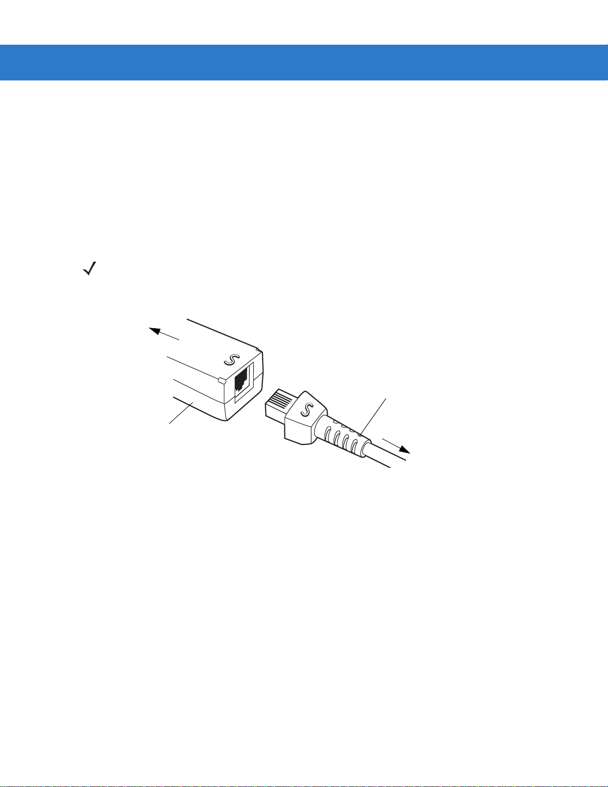
Connecting a Synapse Cable Interface
NOTE Refer to the Synapse Interface Guide provided with the Synapse cable for detailed setup instructions.
Symbol’s Synapse Smart Cables enable interfacin g to a variety of hosts. The appropriate Synapse cable has the
built-in intelligence to detect the host to which it is connected.
Figure 1-3
1. Plug the Synapse adapter cable (p/n 25-32463-xx) into the bottom of the scann er, as described in Installing the
2. Align the ‘S’ on the Synapse adapter cable with the ‘S’ on the Synapse Smart Cable and plug the cable in.
3. Connect the other end of the Synapse Smart Cable to the host.
Connecting Power (if required)
If the host does not provide power to the scanner, an external power connection to the scanner is required. To
connect power:
1. Connect the interface cable to the bottom of the scanner, as described in Installing the Interface Cable on page
2. Connect the other end of the interface cable to the host (refer to the host manual to locate the correct port).
3. Plug the power supply into the power jack on the interface cable. Plug the other end of the power supp ly into
Synapse Cable Connection
Interface Cable on page 1-3.
1-3.
an AC outlet.
Page 23

Getting Started 1 - 5
Configuring the Scanner
To configure the scanner, use the bar codes included in this manual, or the 123Scan configuration program.
See Chapter 4, User Preferences, Chapter 12, Symbologies and Chapter 13, Miscellaneous Scanner Options for
information about programming the scanner using b ar code menus. Also see each ho st-specific chapter to set up a
connection to a specific host type.
See Chapter 11, 123Scan to configure the scanner using this configuration program. A help file is available in the
program.
Page 24

1 - 6 Symbol LS4208 Product Reference Guide
Page 25

Chapter 2 Scanning
Beeper
LED
Trigger
Scan
Window
Introduction
This chapter provides beeper and LED definitions, techniqu es involved in scanning bar codes, general instructions
and tips about scanning, and decode zone diagram.
Figure 2-1
Parts
Page 26

2 - 2 Symbol LS4208 Product Reference Guide
Beeper Definitions
The scanner issues different beep sequences and patterns to indicate status. Table 2-1 defines beep sequences
that occur during both normal scanning and while programming the scanner.
Table 2-1
Standard Use
Low/medium/high beeps Power up.
Short high beeps A bar code symbol was decoded (if decode beeper is
Clicking Occurs during PDF417 decoding to indicate proper
4 long low beeps A transmission error was detected in a scanned symbol.
5 low beeps Conversion or format error.
Low/high/low beeps Advanced Data Formatting (ADF) transmit error. See
High/high/high/low beeps RS-232 receive error.
Parameter Menu Scanning
Short high beeps Correct entry scanned or correct menu sequence
Beeper Definitions
Beeper Sequence Indication
enabled).
alignment, motion, and distance.
The data is ignored. This occurs if a unit is not properly
configured. Check option setting.
Chapter 14, Advanced Data Formatting
performed.
.
Low/high beeps Input error, incorrect bar code or “Cancel” scanned, wrong
entry, incorrect bar code programming sequence; remain in
program mode.
High/low beeps Keyboard parameter selected. Enter value using bar code
keypad.
High/low/high/low beeps Successful program exit with change in the parameter
setting.
Low/high/low/high beeps Out of host parameter storage space. Scan
Parameters on page 4-3
Code 39 Buffering
High/low beeps New Code 39 data was entered into the buffer.
3 Beeps - long high beeps Code 39 buffer is full.
Low/high/low beeps The Code 39 buffer was erased or there was an attempt to
clear or transmit an empty buffer.
Low/high beeps A successful transmission of buffered data.
.
Default
Page 27
Scanning 2 - 3
Table 2-1
Host Specific
Beeper Definitions (Continued)
USB only
4 short high beeps Scanner has not completed initialization. Wait several
Scanner gives a power-up beep after
scanning a USB Device Type.
This power-up beep occurs more than once. The USB bus may put the scanner in a state where power to
RS-232 only
1 short high beep A <BEL> character is received and Beep on <BEL> is
LED Definitions
In addition to beeper sequences, the scanner communicates with the user using a two-color LED display. T able 2-2
defines LED colors that display during scanning.
Beeper Sequence Indication
seconds and scan again.
Communication with the bus must be established before the
scanner can operate at the highest power level.
the scanner is cycled on and off more than once. This is
normal and usually happens when the host cold boots.
enabled.
Table 2-2
Off No power is applied to the scanner, or the scanner is on and ready to scan.
Green A bar code was successfully decoded.
Red A data transmission error or scanner malfunction occurred.
Standard LED Definitions
LED Indication
Page 28

2 - 4 Symbol LS4208 Product Reference Guide
Single Scan Line Pattern
Open Raster Pattern
Y-Axis
Y-Axis
Horizontal Displacement (X - Axis)
Scan Patterns
The scanner emits several scanning patterns, described as follows. To select a pattern, see Scan Pattern on page
4-6.
Single-Line Only
The laser has no up and down scan line movement (no raster).
Figure 2-2
Single-Line Only Scan Pattern
Multi-Line Smart Raster
The scan line begins as a single line and moves up and down (rasters) when a partial scan of a bar code is
detected, or no bar code is decoded 500 ms after the trigger is pulled. If the scanner detects a PDF417
(Symbol LS4208-PR only), GS1 DataBar, or Composite Code, it immediately rasters, opening to a full, optimized
raster pattern as soon as the scanner is properly aligned over the bar code.
Figure 2-3
Multi-Line Smart Raster Scan Pattern
Multi-line Always Raster
Rastering (up and down scan line movement) begins immediately to decode 1D, PDF417 (Symbol LS42 08-PR
only), GS1 DataBar, and Composite Codes.
Figure 2-4
Multi-Line Always Raster Scan Pattern
Page 29

Scanning Modes
Single-Line Mode
Multi-Line Raster Mode
The Symbol LS4208 accommodates both hand-held and hands-free modes. In hand-held use, you pull the trigger
to activate the scan pattern and decode the bar code. In hands-free mode, the scanner sits in the Intellistand and
automatically decodes a bar code presented in its field of view.
Scanning in Hand-Held Mode
Install and program the scanner (see Setting Up the Scanner on page 1-3). For assistance, contact Motorola
Enterprise Mobility Support. See page xv for contact information.
To scan in hand-held mode:
1. Ensure all connections are secure. (See the host chapter for the scanner.)
2. Aim the scanner at the bar code.
3. Press the trigger.
Scanning 2 - 5
Figure 2-5
Upon successful decode, the scanner beeps and the LED turns green. For more informatio n about beeper and
LED definitions, see Table 2-1 and Table 2-2.
Scanning in Hand-Held Mode
NOTE Scan line lengths vary depending on the scan line width selected (see Scan Line Width on page 4-7). A full
scan line width is the default. Medium and short scan line widths are useful for scannin g me nu s or
pick-lists.
Page 30
2 - 6 Symbol LS4208 Product Reference Guide
012345
012345
012345
012345
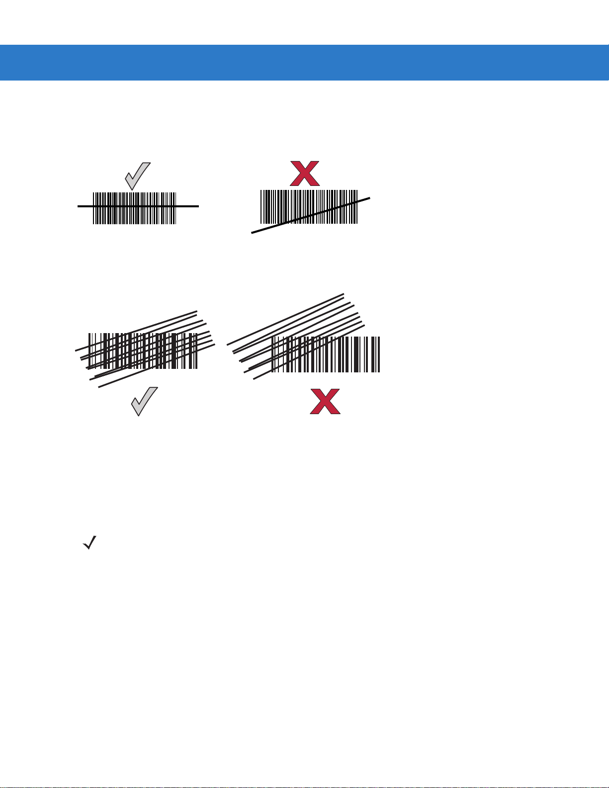
Aiming
On a typical UPC 100% hold the scanner between contact and 19 inches from the symbol (see Symbol LS4208
Decode Zone on page 2-11). When scanning using a single-line scan mode, ensure the scan line crosses every
bar and space of the symbol.
Figure 2-6
Acceptable and Incorrect Single-Line Aiming
When scanning using a multi-line raster mode, at least one scan line must cross every bar and space of the
symbol.
Figure 2-7
Acceptable and Incorrect Multi-Line Aiming
Regardless of the scan mode, the scan line is smaller when the scanner is closer to the symbol and larger when it
is farther from the symbol. Scan symbols with smaller bars or elements (mil size) clos er to the scanner, and those
with larger bars or elements (mil size) farther from the scanner.
Do not hold the scanner directly over the bar code. Laser light reflecting directly back into the scanner from the bar
code is known as specular reflection. This specular reflection can make decoding difficult.
NOTE Scan line lengths vary depending on the scan line width selected (see Scan Line Width on page 4-7). A full
scan line width is the default. Medium and short scan line widths are useful for scannin g me nu s or
pick-lists.
Page 31

Scanning 2 - 7
65
o
65
o
The scanner can be tilted up to 65° forward or back and achieve a successful decode ( Figure 2-8). Sim ple practice
quickly shows what tolerances to work within.
Figure 2-8
Maximum Tilt Angles and Dead Zone
Scanning PDF Symbols
For optimal scanning performance, use rastering mode to scan PDF417 symbols. Adjust the raster to cover the
entire PDF symbol. For large PDF symbols, you may need to manually raster the scanner in order to cover the
entire symbol.
If the pattern does not cover the top and bottom of a PDF symbol, pull the scanner back until it does. Make sure the
scan pattern extends beyond the edges of the bar code.
Figure 2-9
If the vertical scan pattern is not high enough to cover a “tall” PDF417 symbol, move the scanner slowly down
toward the bottom of the symbol, keeping the beam horizontal to the rows, and then slowly back upward to the top .
Alternatively, move the scanner further away from the bar code until the scan pattern covers a larger portion of the
bar code in the vertical direction.
Raster Pattern Expanded Over PDF417 Symbol
Page 32

2 - 8 Symbol LS4208 Product Reference Guide
Aim at the center of the 2D portion
Raster pattern expands to decode
both portions
Figure 2-10
Keep the scan pattern parallel to the symbol rows. Upon successful decode, the scanner beeps and the LED turns
green. (For more information about beeper and LED definitions, see Ta b l e 2- 1 an d Table 2-2.)
Moving Scan Pattern Upward and Downward on “Tall” PDF Symbol
NOTE Raster height varies depending on the option selected (see Raster Height on page 4-8).
Scanning Composite Bar Codes
Composite Code is a combination of a 1D symbol (GS1 DataBar, UPC/EAN or GS1-128) and a 2D symbol (CC-A,
CC-B or CC-C). When scanning a Composite Code:
•
Keep the scan pattern parallel to the symbol’s rows.
•
Hold the scanner as still as possible.
•
Hold the scanner at an angle which does not cause specular reflection.
•
Hold the scanner close for small symbols, and farther away for large symbols. Practice shows what works.
•
Aim the scan line at the middle of the 2D portion. The scan pattern rasters and decodes both the 2D and 1D
portion of the Composite Code.
Figure 2-11
Scanning Composite Codes
Page 33

Scanning 2 - 9
Scanning in Hands-Free Mode
The optional Intellistand adds greater flexibility to scanning operation. When the scanner is seated in the stand’s
“cup,” the scanner’s built-in sensor places the scanner in hands-free mode. Wh en the scanner is removed from the
stand, it automatically switches modes to operate in its normal hand-held triggered mode.
Assemble the Stand
Figure 2-12
Assembling Intellistand
Page 34

2 - 10 Symbol LS4208 Product Reference Guide
Scanner Holder
Height Adjustment Knob
Angle Adjustment Knob
Cup
Scanning with Intellistand
When the scanner is placed in the Intellistand, the scan pattern selected in hand-held triggered mode continues
(see Scan Pattern on page 4-6).
To operate the scanner in Intellistand:
1. Ensure the scanner is properly connected to the host (see the ap propriate host chapter for information on h ost
connections).
2. Insert the scanner in Intellistand by placing the front of the scanner into the stand’s “cup.”
Figure 2-13
3. Use the Intellistand’s adjustment knobs to adjust the height and angle of the scanner.
4. Present the bar code.
5. Upon successful decode, the scanner beeps and the LED turns green. F or more information abou t beeper and
Inserting the Scanner in the Intellistand
NOTE When the bar code is in view, the scanner emits a full scan line. After 3 minutes, the
scanner automatically switches to a reduced scan line. After 1 hour, the scanner automatically
switches to blink mode.
LED definitions, see Table 2-1 and Table 2-2.
Page 35

Symbol LS4208 Decode Zone
Scanning 2 - 11
Note: Typical performance at 73° F (23° C) on
high quality symbols in normal room light.
LS4208
5 mil
1.5
10 mil
*
13 mil
20 mil
** 6.6 mil PDF417 (3:1)
1.5
5.5
in. cm
25.4
10
W
i
d
t
h
o
f
F
i
e
l
d
14.5
19
29
12.7
5
00
12.75
25.410
7
** 10 mil PDF417 (3:1)
10
25.4
11.75
15
38.1
Depth of Field
20
50.8
0.75
in.
0
cm
0
* Minimum distance determined by symbol length and scan angle
** LS4208-PR (PDF417) version only
Figure 2-14
5
12.7
Symbol LS4208 Decode Zone
25
63.5
30
76.2
Page 36

2 - 12 Symbol LS4208 Product Reference Guide
Page 37

Chapter 3 Maintenance, Troubleshooting &
Technical Specifications
Introduction
This chapter provides suggested scanner maintenance, troubleshooting, technical specifications, and signal
descriptions (pinouts).
Maintenance
Cleaning the exit window is the only maintenance required. A dirty window may affect scanning accuracy.
•
Do not allow any abrasive material to touch the window
•
Remove any dirt particles with a damp cloth
•
Wipe the window using a tissue moistened with ammonia/water
•
Do not spray water or other cleaning liquids directly into the window.
Page 38

3 - 2 Symbol LS4208 Product Reference Guide
Troubleshooting
Table 3-1
Beeper Indications
The scanner emits frequent
beeps.
Scanner emits low/high/low
beeps.
Troubleshooting
Problem Possible Causes Possible Solutions
No power to the scanner. Check the system power. If the
configuration requires a power supply,
re-connect the power supply.
Incorrect host interface cable is used. Verify that the correct host in terface cable is
used. If not, connect the correct host
interface cable.
Interface/power cables are loose. Check for loose cable connections and
re-connect cables.
ADF transmit error. See
Invalid ADF rule is detected. See
The Code 39 buffer was erased or
there was an attempt to clear or
transmit an empty buffer.
Chapter 14, Advanced Data
Formatting
Formatting
Normal when scanning the Code 39
Buffering
attempt to transmit an empty Code 39
buffer.
.
Chapter 14, Advanced Data
.
Clear Buffer
bar code or upon
Scanner emits low/high
beeps.
Scanner emits
low/high/low/high beeps.
Scanner emits high/low
beeps.
Scanner emits
high/high/high/low beeps.
Scanner emits four long low
beeps.
Scanner emits four short
high beeps (USB only).
Input error, incorrect bar code or
Cancel
Out of host parameter storage space. Scan
Out of memory for ADF rules. Reduce the number of ADF rules or the
During programming, indicates out of
ADF parameter storage space.
The scanner is buffering Code 39
data.
RS-232 receive error. Normal during host reset. Otherwise, set the
A transmission error was detected in
a scanned symbol. The data is
ignored.
Scanner has not completed
initialization.
bar code was scanned.
Scan the correct numeric bar codes within
range for the parameter programmed.
Default Parameters on page 4-3
number of steps in the ADF rules.
Erase all rules and re-program with shorter
rules.
Normal.
scanner's RS-232 parity to match the host
setting.
This occurs if a unit is not properly
configured. Check option setting.
Wait several seconds and scan again.
.
Page 39

Maintenance, Troubleshooting & Technical Specifications 3 - 3
Table 3-1
Decoding Bar Codes
Scanner emits the laser, but
does not decode the bar
code.
Scanner decodes bar code,
but does not transmit the
data to the host.
Scanner emits five long low
beeps after a bar code is
decoded.
Troubleshooting (Continued)
Problem Possible Causes Possible Solutions
Scanner is not programmed for the
correct bar code type.
Bar code symbol is unreadable. Scan test symbols of the same bar code
Distance between scanner and bar
code is incorrect.
The scan line is not crossing every
bar and space of the symbol.
Scanner is not programmed for the
correct host type.
Interface cable is loose. Check for loose cable connection and
Conversion or format error was
detected.
The scanner’s conversion
parameters are not properly
configured.
Program the scanner to read that type of bar
code. See
type to determine if the bar code is defaced.
Move the scanner closer to or further from
the bar code. See
Zone on page 2-11
Move the symbol until the scan line is within
the acceptable aiming pattern. See
2-6 on page 2-6
Scan the appropriate host type
programming bar code. See the chapter
corresponding to the host type.
re-connect cable.
Ensure the scanner’s conversion
parameters are properly configured.
Chapter 12, Symbologies
Symbol LS4208 Decode
.
.
.
Figure
Conversion or format error was
detected.
An ADF rule was set up with
characters that can't be sent for the
host selected.
Conversion or format error was
detected.
A bar code was scanned with
characters that can't be sent for that
host.
Change the ADF rule, or change to a host
that can support the ADF rule.
Change the bar code, or change to a host
that can support the bar code.
Page 40

3 - 4 Symbol LS4208 Product Reference Guide
Table 3-1
Troubleshooting (Continued)
Problem Possible Causes Possible Solutions
Host Displays
Host displays scanned data
incorrectly.
Trigger
Nothing happens when the
trigger is pulled.
Scanner is not programmed to work
with the host.
Ensure the proper host is selected.
Scan the appropriate host type
programming bar code.
For RS-232, set the scanner's
communication parameters to match the
host's settings.
For a USB HID keyboard or Keyboard
Wedge configuration, program the system
for the correct keyboard type and language,
and turn off the CAPS LOCK key.
Program the proper editing options (e.g.,
ADF, UPC-E to UPC-A Conversion).
Check the scanner’s host type parameters
or editing options.
No power to the scanner. Check the system power. If the
configuration requires a power supply,
re-connect the power supply.
The laser does not appear
when the trigger is pulled.
NOTE If after performing these checks the symbol still does not scan, contact the distributor or Motorola
Enterprise Mobility Support. See page xv for contact information.
Interface/power cables are loose. Check for loose cable connections and
re-connect cables.
No power to the scanner. Check the system power. If the
configuration requires a power supply,
re-connect the power supply.
Incorrect host interface cable is used. Verify that the correct host in terface cable is
used. If not, connect the correct host
interface cable.
Interface/power cables are loose. Check for loose cable connections and
re-connect cables.
Page 41

Technical Specifications
Maintenance, Troubleshooting & Technical Specifications 3 - 5
Table 3-2
Physical Characteristi cs
Dimensions: 6.7 in. H x 3.7 in. L x 2.7 in. W
Weight (without cable) Approximately 6.4 oz. (181 g)
Voltage & Current
Color Cash Register White or Twilight Black
Performance Characteristics
Light Source (Laser) 650nm laser diode
Motor Frequency 50Hz
Decode Rate 200 decodes per second
Roll Tolerance ± 35°
Pitch Tolerance ± 60°
Technical Specifications
Item Description
Symbol LS4208-SR
Symbol LS4208-PR
(17 cm H x 9.3 cm L x 6.8 cm W)
5 +/-10%VDC @ 140 mA (Stand by: <35 mA)
5 +/-10%VDC @ 155 mA (Stand by: <60 mA)
Ya w Tolerance ± 60°
Nominal Working Distance See
Minimum Resolution 5 mil (linear bar codes)
Print Contrast Minimum 25% minimum reflectance
Multi-Line Aiming Coverage At 5 in. reading distance: ~ 0.5 in. (1.3 cm)
Motion Tolerances Horizontal Velocity: 200 in. (508 cm) / sec
Decode Capability UPC/EAN and with supplementals, Bookland EAN, Code 39, Code 39
Symbol LS4208 Decode Zone on page 2-11
5 mil (uPDF & PDF, 3:1, Y:X aspect ratio)
At 10 in. reading distance: ~ 1 in. (2.5 cm)
Vertical Velocity: 200 in. (508 cm) / sec
Angular Velocity: 200 in. (508 cm) / sec
Full ASCII, Trioptic Code 39, GS1DataBar Variants, GS1-128, Code
128, Code 128 Full ASCII, Code 93, Codabar (NW1), Code 11,
Interleaved 2 of 5, Discrete 2 of 5, Chinese 2 of 5, MSI, IATA, Code 32,
PDF417, MicroPDF417, Composite Codes
Page 42

3 - 6 Symbol LS4208 Product Reference Guide
Table 3-2
Interfaces Supported RS-232C (St andard, Nixdorf, ICL, & Fujit su); IBM 468x/469x; Keyboard
User Environment
Operating Temperature 32° to 122° F (0° to 50° C)
Storage Temperature -40° to 158° F (-40° to 70° C)
Humidity 5% to 95%, non-condensing
Drop Specifications Withstands multiple 6 ft./1.825 m drops to concrete
Ambient Light Tolerance Tolerant to typical artificial indoor and natural outdoor (direct sunlight)
Technical Specifications (Continued)
Item Description
Wedge; USB (Standard, IBM SurePOS, Macintosh); Laser/Wand
Emulation.
Synapse Adaptive Connectivity allows for connectivity to interfaces
above and many non-standard interfaces.
lighting conditions. Fluorescent, Incandescent, Mercury Vapor, So dium
Vapor, LED: 450 Ft Candles (4,844 Lux) Sunlight: 8000 Ft Candles
(86,111 Lux)
Note: LED lighting with high AC ripple content can impact scanning
performance.
EAS Support Optional Checkpoint Electronic Article Surveillance (EAS)
Beeper Volume User-selectable: three levels
Beeper Tone User-selectable: three tones
ESD 15 kV air discharge
8 kV indirect discharge
Page 43

Scanner Signal Descriptions
Cable interface port
Interface cable
modular connector
Bottom of
scanner
PIN 1
PIN 10
Maintenance, Troubleshooting & Technical Specifications 3 - 7
Figure 3-1
Scanner Cable Pin-outs
Page 44

3 - 8 Symbol LS4208 Product Reference Guide
The signal descriptions in Table 3-3 apply to the connector on the scanner and are for reference only .
Table 3-3
Pin IBM Synapse RS-232
1 Reserved SynClock Reserved Reserved Reserved Jump to Pin 6
2 Power Power Power Power Power Power
3 Ground Ground Ground Ground Ground Ground
4 IBM_A(+) Reserved TxD KeyClock DBP Reserved
5 Reserved Reserved RxD TermData CTS D +
6 IBM_B(-) SynData RTS KeyData RTS Jump to Pin 1
7 Reserved Reserved CTS TermClock Reserved D 8 Reserved Reserve d Reserved Reserved Reserved Reserved
9 EAS EAS EAS EAS EAS EAS
10EASEASEASEASEASEAS
Scanner Signal Pin-outs
Keyboard
Wedge
Wand USB
Page 45

Chapter 4 User Preferences
*High Frequency
Feature/Option
* Indicates Default
Introduction
If desired, program the scanner to perform various functions, or activate different features. This chapter describes
each user preference feature and provides the programming bar codes necessary for selecting these features.
The scanner ships with the settings shown in the User Preferences Default Table on page 4-2 (also see Appendix
A, Standard Default Parameters for all host device and miscellaneous defaults). If the default values suit
requirements, programming may not be necessary.
To set feature values, scan a single bar code or a short bar code sequence. The settings are stored in non -vola tile
memory and are preserved even when th e sca nn e r is powered down.
If not using a Synapse or USB cable, select a host type (see each host chapter for specific host information) after
the power-up beeps sound. This is only necessary upon the first power-up when connected to a new host.
To return all features to their default values, see Default Parameters on page 4-3. Throughout the programming bar
code menus, default values are indicated with asterisks (
*).
Scanning Sequence Examples
In most cases, scanning one bar code sets the parameter value. For example, to set the beeper tone to high, scan
the High Frequency (beeper tone) bar code listed under Beeper Tone on page 4-4. The scanner issues a fast
warble beep and the LED turns green, signifying a suc c essful parameter entry.
Other parameters, such as Serial Response Time-Out or Data Transmission Format s , require scanni ng several
bar codes. See these parameter descriptions for this procedure.
Errors While Scanning
Unless otherwise specified, when an error is made during a scanning sequence, just re-scan the correct
parameter.
Page 46

4 - 2 Symbol LS4208 Product Reference Guide
User Preferences Parameter Defaults
Table 4-1 lists the defaults for user preferences para meters. To change any option, scan the appropriate bar
code(s) provided in the User Preferences section beginning on page 4-3.
NOTE See Appendix A, Standard Default Parameters for all user preferences, hosts, symbologies, and
miscellaneous default parameters.
Table 4-1
User Preferences
Set Default Parameter Restore Defaults 4-3
Parameter Bar Code Scanning Enable 4-4
Beeper Tone Medium 4-4
Beeper Volume High 4-5
Power Mode Continuous On 4-5
Scan Pattern Multi-line Always Raster 4-6
Scan Line Width Full Width 4-7
Raster Height Adjustable Raster 4-8
Laser On Time 3.0 Sec 4-9
Beep After Good Decode Enable 4-9
PDF Decode Feedback Disable 4-10
User Preferences Default Table
Parameter Default
Page
Number
Page 47

User Preferences
Default Parameters
The scanner can be reset to two types of defaults: factory defaults or custom defaults. Scan the appropriate bar
code below to reset the scanner to its default settings and/or set the scanner’s current settings as the custom
default.
•
Restore Defaults - Resets all default parameters as follows:
• If custom default values were configured (see Write to Custom Defaults), the custom default values are
set for all parameters each time the Restore Defaults bar code below is scanned.
• If no custom default values were configured, th e factory default values are set for all p arameters each time
the Restore Default s bar code below is scan ned. (For factory default values, see Table A-1 on page A-1.)
•
Set Factory Defaults - Scan the Set Factory Defaults bar code below to elim inate all custom defau lt values
and set the scanner to factory default values. (For factory default values, see Table A-1 on page A-1.)
•
Write to Custom Defaults - Custom default parameters can be configured to set unique default valu es for all
parameters. After changing all parame ters to the desired default values, scan the Write to Custom Default s
bar code below to configure custom defaults.
User Preferences 4 - 3
*Restore Defaults
Write to Custom Defaults
Set Factory Defaults
Page 48

4 - 4 Symbol LS4208 Product Reference Guide
Parameter Bar Code Scanning
To disable the decoding of parameter bar codes, including the Set Defaults parameter bar codes, scan the
Disable Parameter Scanning bar code below. To enable decoding of parameter bar codes, scan Enable
Parameter Scanning.
*Enable Parameter Bar Code Scanning
(01h)
Disable Parameter Bar Code Scanning
(00h)
Beeper Tone
To select a decode beep frequency (tone), scan the Low Frequency, Medium Frequency, or High Frequency bar
code.
Low Frequency
*Medium Frequency
(Optimum Settings)
High Frequency
Page 49

Beeper Volume
To select a beeper volume, scan the Low Volume, Medium Volume, or High Volume bar code.
Low Volume
Medium Volume
User Preferences 4 - 5
*High Volume
Power Mode
This parameter determines whether or not power remains on after a decode attempt. When in reduced power
mode, the scanner enters into a low power consumption mode to preserve battery life after each decode attempt.
When in continuous power m od e , p ow er r em a ins on a fter ea ch decode attempt.
*Continuous On
Reduced Power Mode
Page 50

4 - 6 Symbol LS4208 Product Reference Guide
Scan Pattern
This parameter determines the pattern (mode) of scanning. Scan the appropriate bar code below to set the
scanning mode.
•
Single-line Only - Scan Single-line Only for a single-line scan mode. The laser has no up and down scan
line movement (no raster). (For an example of a single-line scan, see Figure 2-6 on page 2-6.)
•
Multi-line Smart Raster - The scan line begins as a single line, and immediately rasters upon seeing a
stacked GS1 DataBar code or a 2D variant. (For an example of a multi-line scan, see Figure 2-7 on page
2-6.)
•
Multi-line Always Raster (default) - Scan Multi-line Always Raster for rastering (up and down scan line
movement) to begin immediately.
Single-line Only
(No Raster)
*Multi-line Always Raster
Multi-line Smart Raster
Page 51

Scan Line Width
Scan a bar code below to set the scan line width.
*Full Width
User Preferences 4 - 7
Medium Width
Small Width
Page 52

4 - 8 Symbol LS4208 Product Reference Guide
Raster Height
This parameter determines the scanner’s raster height when scanning PDF symbols only.
•
Short Raster - Scan Short Raster to use the standard 1D raster height of approximately 4o. This option
provides the best performance on MicroPDF and short PDF symbols.
•
Tall Raster - Scan Tall Raster for a raster of approximately 50% t aller than the short raster, opening to about
o
6
and slowing to capture bar code data more efficiently. This provides the best performance on tall PDF
symbols.
•
Adjustable Raster (default) - This option starts as a short raster, then opens to a tall raster and slows half a
second later. Use this option when scanning a variety of symbol heights.
Short Raster
*Adjustable Raster
Tall Raster
Page 53

User Preferences 4 - 9
Laser On Time
This parameter sets the maximum time that decode processing continues during a scan attempt. It is
programmable in 0.1 second increments from 0.5 to 9.9 seconds. The default Laser On Time is 3.0 seconds.
To set a Laser On Time, scan the bar code below. Next, scan two numeric bar codes beginning on page D-1 in
Appendix D, Numeric Bar Codes that correspond to the desired on time. Single digit numbers must have a lea ding
zero. For example, to set an On Time of 0.5 seconds, scan the bar code below, then scan the “0” and “5” bar
codes. If an error is made, or the selection needs to be changed, scan Cancel on page D-3.
Laser On Time
Beep After Good Decode
Scan a bar code below to select whether or not the scanner beeps after a good decode. If Do Not Beep After
Good Decode is selected, the beeper still operates during parameter menu scanning and indicates error
conditions.
*Beep After Good Decode
(Enable)
Do Not Beep After Good Decode
(Disable)
Page 54

4 - 10 Symbol LS4208 Product Reference Guide
PDF Decode Feedback
Scan a bar code below to select whether or not the scanner emits a clicking sound during PDF417 decoding.
This clicking helps the user ensure proper alignment, motion, and distance during decoding. The scanner issues a
standard decode beep upon successfully decoding the bar code.
Enable PDF Decode Feedback
*Disable PDF Decode Feedback
Page 55

Chapter 5 Keyboard Wedge Interface
*North American
Feature/Option
* Indicates Default
Introduction
This chapter describes how to set up a Keyboard Wedge interface with the scanner. With this interface, the
scanner is connected between the keyboard and host compu ter, and translates bar code data into keystrokes. The
host computer accepts the keystrokes as if they originated from the keyboard. This mode adds bar code reading
functionality to a system designed for manual keyboard input. Keyboard keystrokes are simply passed through.
Throughout the programming bar code menus, default values are indicated with asterisks (
*).
Page 56

5 - 2 Symbol LS4208 Product Reference Guide
Male DIN Connector
Female DIN Connector
Keyboard Connector
Connecting a Keyboard Wedge Interface
Figure 5-1
Keyboard Wedge Connection with Y-cable
To connect the Keyboard Wedge interface Y-cable:
NOTE Interface cables vary depending on configuration. The connectors illustrated in Figure 5-1 are examples
only. The connectors may be different than those illustrated, but the steps to connect the scanner are the
same.
1. Turn off the host and unplug the keyboard connector.
2. Attach the modular connector of the Y-cable to the cable interface port on the scanner. (See Installing the
Interface Cable on page 1-3.)
3. Connect the round male DIN host connector of the Y-cable to the keyboard port on the host device.
4. Connect the round female DIN keyboard connector of the Y-cable to the keyboard connector.
5. If needed, attach the optional power supply to the connector in the middle of the Y-cable.
6. Ensure that all connections are secure.
7. Turn on the host system.
8. Select the Keyboard Wedge host type by scanning the appropriate bar code from Keyboard Wedge Host
Parameters on page 5-4.
9. To modify any other parameter options, scan the appropriate bar codes in this chapter.
Page 57

Keyboard Wedge Parameter Defaults
Table 5-1 lists the defaults for Keyboard Wedge host parameters. To change any option, scan the appropriate bar
code(s) in the Keyboard Wedge Host Parameters section beginning on page 5-4.
NOTE See Appendix A, Standard Default Parameters for all user preferences, hosts, symbologies, and
miscellaneous default parameters.
Keyboard Wedge Interface 5 - 3
Table 5-1
Keyboard Wedge Host Parameters
Keyboard Wedge Host Type
Country Types (Country Codes) North American 5-5
Ignore Unknown Characters Send 5-6
Keystroke Delay No Delay 5-7
Intra-Keystroke Delay Disable 5-7
Alternate Numeric Keypad Emulation Disable 5-8
Caps Lock On Disable 5-8
Caps Lock Override Disable 5-9
Convert Wedge Data No Convert 5-10
Function Key Mapping Disable 5-10
FN1 Substitution Disable 5-11
Keyboard Wedge Host Default Table
Parameter Default
IBM PC/AT& IBM PC Compatibles
1
5-4
Page
Number
Send and Make Break Send 5-11
1
User selection is required to configure this interface and this is the most common
selection.
Page 58

5 - 4 Symbol LS4208 Product Reference Guide
Keyboard Wedge Host Parameters
Keyboard Wedge Host Types
Select the Keyboard Wedge host by scanning one of the bar codes below.
IBM PC/AT & IBM PC Compatibles
NCR 7052
1
NOTE
User selection is required to configure this interface and this is the most common selection.
1
IBM AT Notebook
Page 59

Keyboard Wedge Interface 5 - 5
Keyboard Wedge Country Types (Country Codes)
Scan the bar code corresponding to the keyboard type. If the keyboard type is not listed, see Alternate Numeric
Keypad Emulation on page 5-8.
*North American
German Windows
French Windows
French Canadian Windows XP/2000
French Canadian Windows 95/98
Spanish Windows
Italian Windows
Page 60

5 - 6 Symbol LS4208 Product Reference Guide
Keyboard Wedge Country Types (continued)
Swedish Windows
UK English Windows
Japanese Windows
Portuguese-Brazilian Windows
Ignore Unknown Characters
Unknown characters are characters the host does not recognize. When Send Bar Codes With Unknown
Characters is selected, all bar code data is sent except for unknown characte rs, and no erro r be eps sound on the
scanner. When Do Not Send Bar Codes With Unknown Characters is selected, bar code data is sent up to the
first unknown character, then the scanner issues an error beep.
*Send Bar Codes with Unknown Characters
Do Not Send Bar Codes with Unknown Characters
Page 61

Keyboard Wedge Interface 5 - 7
Keystroke Delay
This is the delay in milliseconds between emulated keystrokes. Scan a bar code below to increase the delay when
hosts require a slower transmission of data.
*No Delay
Medium Delay (20 msec)
Long Delay (40 msec)
Intra-Keystroke Delay
When enabled, an additional delay is inserted between each emulated key depression and release. This sets the
Keystroke Delay parameter to a minimum of 5 msec as well.
Enable Intra-Keystroke Delay
*Disable Intra-Keystroke Delay
Page 62

5 - 8 Symbol LS4208 Product Reference Guide
Alternate Numeric Keypad Emulation
This allows emulation of most other country keyboard types not listed in Keyboard W ed ge Co untry Types (Country
Codes) on page 5-5 in a Microsoft
Enable Alternate Numeric Keypad
®
operating system environment.
*Disable Alternate Numeric Keypad
Caps Lock On
When enabled, the scanner emulates keystrokes as if the Caps Lock key is always pressed. Note that if both Caps
Lock On and Caps Lock Override are enabled, Caps Lock Override takes precedence.
Enable Caps Lock On
*Disable Caps Lock On
Page 63

Keyboard Wedge Interface 5 - 9
Caps Lock Override
When enabled, on A T or AT Notebook hosts, the keyboard ignores the state of the Cap s Lock key. Therefore, an ‘A ’
in the bar code is sent as an ‘A’ no matter what the state of the keyboard’s Caps Lock key.
Note that if both Caps Lock On and Caps Lock Override are enabled, Caps Lock Override takes precedence.
Enable Caps Lock Override
*Disable Caps Lock Override
Page 64

5 - 10 Symbol LS4208 Product Reference Guide
Convert Wedge Data
When enabled, the scanner will convert all bar code data to the selected case.
Convert to Upper Case
Convert to Lower Case
*No Convert
Function Key Mapping
ASCII values under 32 are normally sent as control key sequences (see Table 5-2 on page 5-13). When this
parameter is enabled, the keys in bold are sent in place of the standard key mapping. Table entries that do not
have a bold entry remain the same whether or not this parameter is enabled.
Enable Function Key Mapping
*Disable Function Key Mapping
Page 65

Keyboard Wedge Interface 5 - 11
FN1 Substitution
When enabled, the scanner replaces FN1 characters in a GS1-128 bar code with a keystroke chosen by the user
(see FN1 Substitution Values on page 13-6).
Enable FN1 Substitution
*Disable FN1 Substitution
Send Make and Break
When enabled, the scan codes for releasing a key are not sent.
*Send Make and Break Scan Codes
Send Make Scan Code Only
Page 66

5 - 12 Symbol LS4208 Product Reference Guide
5001
5002
5003
5004
5005
5006
5007
5008
5009
5010
7009
7008
7013
7012
7004
7011
7003
7002
7014
5007
5008
5010
5002
5003
5004
5005 5006
1046
1045
5014
1043
5013
5015
5016
5018
5019
5001
5017
7013
5011
(7013 if double key)
(1048 if double key)
1048
5012
5009
5007
5008
5010
5002
5003
5004
5005 5006
1046
1045
5014
1043
5013
5015
5016
5018
5019
1086
1087
1088
1089
1090
5001
1066
1072
1073
1079 1080
1065
1070
1076
1077
1083 1084
1071
1078
1085
1069
5017
7013
5011
1082
1075
1068
1067
(1043 if double key)
(1048 if double key)
1048
5012
5009
1074
1081
Keyboard Maps
The following keyboard maps are provided for pr efix/suffix keystroke parameters. To program the prefix/suffix
values, see the bar codes on page 13-3.
Figure 5-2
Figure 5-3
IBM PC/AT
NCR 7052 32-KEY
Figure 5-4
NCR 7052 58-KEY
Page 67

ASCII Character Set for Keyboard Wedge
NOTE Code 39 Full ASCII interprets the bar code special character ($ + % /) preceding a Code 39 character and
assigns an ASCII character value to the pair. For example, when Code 39 Full ASCII is enabled and a +B
is scanned, it is interpreted as b, %J as ?, and %V as @. Scanning ABC%I outputs the keystroke
equivalent of ABC >.
Keyboard Wedge Interface 5 - 13
Table 5-2
Keyboard Wedge ASCII Character Set
ASCII Value
Full ASCII Code 39
Encode Character
1001 $A CTRL A
1002 $B CTRL B
1003 $C CTRL C
1004 $D CTRL D
1005 $E CTRL E
1006 $F CTRL F
1007 $G CTRL G
1008 $H
1009 $I
CTRL H/
CTRL I/
1010 $J CTRL J
1011 $K CTRL K
1012 $L CTRL L
Keystroke
BACKSPACE
1
HORIZONTAL TAB
1
1013 $M
CTRL M/
ENTER
1014 $N CTRL N
1015 $O CTRL O
1016 $P CTRL P
1017 $Q CTRL Q
1018 $R CTRL R
1019 $S CTRL S
1020 $T CTRL T
1021 $U CTRL U
1
The keystroke in bold is sent only if the “Function Key Mapping” is
enabled. Otherwise, the unbolded keystroke is sent.
1
Page 68

5 - 14 Symbol LS4208 Product Reference Guide
Table 5-2
Keyboard Wedge ASCII Character Set (Continued)
ASCII Value
Full ASCII Code 39
Encode Character
1022 $V CTRL V
1023 $W CTRL W
1024 $X CTRL X
1025 $Y CTRL Y
1026 $Z CTRL Z
1027 %A
CTRL [ /
1028 %B CTRL \
1029 %C CTRL ]
1030 %D CTRL 6
1031 %E CTRL 1032 Space Space
1033 /A !
Keystroke
1
ESC
1034 /B “
1035 /C #
1036 /D $
1037 /E %
1038 /F &
1039 /G ‘
1040 /H (
1041 /I )
1042 /J *
1043 /K +
1044 /L ,
1045 - 1046 . .
1047 /O /
1048 0 0
1049 1 1
1
The keystroke in bold is sent only if the “Function Key Mapping” is
enabled. Otherwise, the unbolded keystroke is sent.
Page 69

Keyboard Wedge Interface 5 - 15
Table 5-2
Keyboard Wedge ASCII Character Set (Continued)
ASCII Value
Full ASCII Code 39
Encode Character
1050 2 2
1051 3 3
1052 4 4
1053 5 5
1054 6 6
1055 7 7
1056 8 8
1057 9 9
1058 /Z :
1059 %F ;
1060 %G <
1061 %H =
1062 %I >
Keystroke
1063 %J ?
1064 %V @
1065 A A
1066 B B
1067 C C
1068 D D
1069 E E
1070 F F
1071 G G
1072 H H
1073 I I
1074 J J
1075 K K
1076 L L
1077 M M
1
The keystroke in bold is sent only if the “Function Key Mapping” is
enabled. Otherwise, the unbolded keystroke is sent.
Page 70

5 - 16 Symbol LS4208 Product Reference Guide
Table 5-2
Keyboard Wedge ASCII Character Set (Continued)
ASCII Value
Full ASCII Code 39
Encode Character
1078 N N
1079 O O
1080 P P
1081 Q Q
1082 R R
1083 S S
1084 T T
1085 U U
1086 V V
1087 W W
1088 X X
1089 Y Y
1090 Z Z
Keystroke
1091 %K [
1092 %L \
1093 %M ]
1094 %N ^
1095 %O _
1096 %W ‘
1097 +A a
1098 +B b
1099 +C c
1100 +D d
1101 +E e
1102 +F f
1103 +G g
1104 +H h
1105 +I i
1
The keystroke in bold is sent only if the “Function Key Mapping” is
enabled. Otherwise, the unbolded keystroke is sent.
Page 71

Keyboard Wedge Interface 5 - 17
Table 5-2
Keyboard Wedge ASCII Character Set (Continued)
ASCII Value
Full ASCII Code 39
Encode Character
1106 +J j
1107 +K k
1108 +L l
1109 +M m
1110 +N n
1111 +O o
1112 +P p
1113 +Q q
1114 +R r
1115 +S s
1116 +T t
1117 +U u
1118 +V v
Keystroke
1119 +W w
1120 +X x
1121 +Y y
1122 +Z z
1123 %P {
1124 %Q |
1125 %R }
1126 %S ~
1
The keystroke in bold is sent only if the “Function Key Mapping” is
enabled. Otherwise, the unbolded keystroke is sent.
Table 5-3
Keyboard Wedge ALT Key Character Set
ALT Keys Keystroke
2065 ALT A
2066 ALT B
2067 ALT C
2068 ALT D
2069 ALT E
Page 72

5 - 18 Symbol LS4208 Product Reference Guide
Table 5-3
2070 ALT F
2071 ALT G
2072 ALT H
2073 ALT I
2074 ALT J
2075 ALT K
2076 ALT L
2077 ALT M
2078 ALT N
2079 ALT O
2080 ALT P
2081 ALT Q
2082 ALT R
Keyboard Wedge ALT Key Character Set (Continued)
ALT Keys Keystroke
2083 ALT S
2084 ALT T
2085 ALT U
2086 ALT V
2087 ALT W
2088 ALT X
2089 ALT Y
2090 ALT Z
Table 5-4
3000 Right Control Key
3048 GUI 0
3049 GUI 1
3050 GUI 2
3051 GUI 3
Keyboard Wedge GIU Key Character Set
GUI Keys Keystrokes
3052 GUI 4
3053 GUI 5
Page 73

Keyboard Wedge Interface 5 - 19
Table 5-4
3054 GUI 6
3055 GUI 7
3056 GUI 8
3057 GUI 9
3065 GUI A
3066 GUI B
3067 GUI C
3068 GUI D
3069 GUI E
3070 GUI F
3071 GUI G
3072 GUI H
3073 GUI I
Keyboard Wedge GIU Key Character Set (Continued)
GUI Keys Keystrokes
3074 GUI J
3075 GUI K
3076 GUI L
3077 GUI M
3078 GUI N
3079 GUI O
3080 GUI P
3081 GUI Q
3082 GUI R
3083 GUI S
3084 GUI T
3085 GUI U
3086 GUI V
3087 GUI W
3088 GUI X
3089 GUI Y
3090 GUI Z
Page 74

5 - 20 Symbol LS4208 Product Reference Guide
Table 5-5
5001 F1
5002 F2
5003 F3
5004 F4
5005 F5
5006 F6
5007 F7
5008 F8
5009 F9
5010 F10
5011 F11
5012 F12
5013 F13
Keyboard Wedge F Key Character Set
F Keys Keystroke
5014 F14
5015 F15
5016 F16
5017 F17
5018 F18
5019 F19
5020 F20
5021 F21
5022 F22
5023 F23
5024 F24
Page 75

Keyboard Wedge Interface 5 - 21
Table 5-6
6042 *
6043 +
6044 undefined
6045 6046 .
6047 /
6048 0
6049 1
6050 2
6051 3
6052 4
6053 5
6054 6
Keyboard Wedge Numeric Keypad Character Set
Numeric Keypad Keystroke
6055 7
6056 8
6057 9
6058 Enter
6059 Num Lock
Page 76

5 - 22 Symbol LS4208 Product Reference Guide
Table 5-7
7001 Break
7002 Delete
7003 Pg Up
7004 End
7005 Pg Dn
7006 Pause
7007 Scroll Lock
7008 Backspace
7009 Tab
7010 Print Screen
7011 Insert
7012 Home
7013 Enter
Keyboard Wedge Extended Keypad Character Set
Extended Keypad Keystroke
7014 Escape
7015 Up Arrow
7016 Dn Arrow
7017 Left Arrow
7018 Right Arrow
Page 77

Chapter 6 RS-232 Interface
*Baud Rate 57,600
Feature/Option
* Indicates Default
Introduction
This chapter describes how to set up the scanner with an RS-232 host. The RS-232 interface is used to connect
the scanner to point-of-sale devices, host computers, or other devices with an available RS-232 port (e.g., com
port).
If the host is not listed in Table 6-2, refer to the documentation for the host d evice to set communication parameters
to match the host.
NOTE The scanner uses TTL RS-232 signal levels, which interface with most system architectures. For system
architectures requiring RS-232C signal levels, Symbol offers different cables providing TTL-to-RS-232C
conversion. Contact Motorola Enterprise Mobility Support for more information.
Throughout the programming bar code menus, default values are indicated with asterisks (
*).
Page 78

6 - 2 Symbol LS4208 Product Reference Guide
Serial Port
Connector to Host
Interface Cable
Power Supply Cable
Connecting an RS-232 Interface
This connection is made directly from the scanner to the host computer.
Figure 6-1
1. Attach the modular connector of the RS-232 interface cable to the cable interface port on the scanner (see
RS-232 Direct Connection
NOTE Interface cables vary depending on configuration. The connectors illustrated in Figure 6-1 are examples
only. The connectors may be different than those illustrated, but the steps to connect the scanner remain
the same.
Installing the Interface Cable on page 1-3).
2. Connect the other end of the RS-232 interface cable to the serial port on the host.
3. Connect the power supply to the serial connector end of the RS-232 interface cable. Plug the power supply
into an appropriate outlet.
4. Select the RS-232 host type by scanning the appropriate bar code from RS-232 Host Types on page 6-6.
5. To modify any other parameter options, scan the appropriate bar codes in this chapter.
Page 79

RS-232 Parameter Defaults
Table 6-1 lists the defaults for RS-232 host parameters. If any option needs to be changed, scan the appropriate
bar code(s) provided in the Parameter Descriptions section beginning on page 6 -4.
NOTE See Appendix A, Standard Default Parameters for all user preferences, hosts, symbologies, and
miscellaneous default parameters.
RS-232 Interface 6 - 3
Table 6-1
RS-232 Host Parameters
RS-232 Host Types Standard 6-6
Baud Rate 9600 6-7
Parity Type None 6-8
Stop Bit Select 1 Stop Bit 6-9
Data Bits (ASCII Format) 8-Bit 6-9
Check Receive Errors Enable 6-10
Hardware Handshaking None 6-10
Software Handshaking None 6-12
Host Serial Response Time-out 2 Sec 6-14
RTS Line State Low RTS 6-15
Beep on <BEL> Disable 6-15
Intercharacter Delay 0 msec 6-16
RS-232 Host Default Table
Parameter Default
Page
Number
Nixdorf Beep/LED Options Normal Operation 6-17
Ignore Unknown Characters Send Bar Code 6-17
Page 80

6 - 4 Symbol LS4208 Product Reference Guide
RS-232 Host Parameters
Various RS-232 hosts are set up with their own parameter default settings (Table 6-2). Selecting the ICL, Fujitsu,
Wincor-Nixdorf Mode A, Wincor-Nixdorf Mode B, Olivetti, Omron, or terminal sets the defaults listed below.
Table 6-2
Transmit Code ID No Yes Yes Yes Yes Yes Yes
Data Transmis sion
Format
Suffix CR/LF
Baud Rate 9600 9600 9600 9600 9600 9600 9600
Parity None Even None Odd O dd Even None
Hardware
Handshaking
Software
Handshaking
Serial Response
Time-out
Stop Bit Select One One One One One One One
Terminal Specific RS-232
Parameter
Standard
(Default)
Data as is Data/
(7013)
None RTS/CTS
None None None None None Ack/Nak None
2 Sec. 9.9 Sec. 2 Sec. 9.9 Sec. 9.9 Sec. 9.9 Sec. 9.9 Sec.
ICL Fujitsu
Suffix
CR
(1013)
Option 3
Wincor-
Nixdorf
Mode A
Data/
Suffix
CR
(1013)
None RTS/CTS
Data/
Suffix
CR
(1013)
Option 3
Wincor-
Nixdorf
Mode B/
OPOS
Data/Suffix Prefix/Data/
CR (1013) ETX (1002) CR (1013)
RTS/CTS
Option 3
Olivetti Omron
Data/Suffix
Suffix
None None
ASCII Format 8-Bit 8-Bit 8-Bit 8-Bit 8-Bit 7-Bit 8-Bit
Beep On <BEL> Disable Disable Disable Disable Disable Disable Disable
RTS Line State Low High Low Low Low = No
data to send
Prefix None None None None None STX (1003) None
*In the Nixdorf Mode B, if CTS is Low, scanning is disabled. When CTS is High, the user can scan
bar codes.
**If Nixdorf Mode B is scanned without the scanner connected to the proper host, it may appear
unable to scan. If this happens, scan a different RS-232 host type within 5 seconds of cycling
power to the scanner.
Low High
Page 81

RS-232 Host Parameters (continued)
Selecting the ICL, Fujitsu, Wincor-Nixdorf Mode A, Wincor-Nixdorf Mode B, OPOS terminal enables the
transmission of code ID characters listed in Table 6-3 below. These code ID characters are not pr ogrammab le an d
are separate from the T ransmit Code ID feature. The Transmit Code ID feature should not be enabled for these
terminals.
RS-232 Interface 6 - 5
Table 6-3
UPC-A A A A A A A
UPC-E E E C C C E
EAN-8/JAN-8 FF FF B B B FF
EAN-13/JAN-13 F F A A A F
Code 39 C <len> None M M M <len> C <len>
Codabar N <len> None N N N <len> N <len>
Code 128 L <len> None K K K <len> L <len>
I 2 of 5 I <len> None I I I <len> I <len>
Code 93 None None L L L <len> None
D 2 of 5 H <len> None H H H <len> H <len>
GS1-128 L <len> None P P P <len> L <len>
MSI None None O O O <len> None
Terminal Specific Code ID Characters
Code Type ICL Fujitsu
Wincor-
Nixdorf
Mode A
Wincor-
Nixdorf
Mode B/OPOS
Olivetti Omron
Bookland EAN F F A A A F
Trioptic None None None None None None
Code 11 None None None None None None
IATA H<len> None H H None None
Code 32 None None None None None None
Page 82

6 - 6 Symbol LS4208 Product Reference Guide
RS-232 Host Types
To select an RS-232 host interface, scan one of the following bar codes.
*Standard RS-232
ICL RS-232
Wincor-Nixdorf RS-232 Mode A
Olivetti ORS4500
OPOS/JPOS
Wincor-Nixdorf RS-232 Mode B
Omron
Fujitsu RS-232
Page 83

RS-232 Interface 6 - 7
Baud Rate
Baud rate is the number of bits of data transmitted per second. Set the scann er's baud rate to match the baud rate
setting of the host device. Otherwise, data may not reach the host device or may reach it in distorted form.
Baud Rate 600
Baud Rate 1200
Baud Rate 2400
*Baud Rate 9600
Baud Rate 4800
Baud Rate 19,200
Baud Rate 38,400
Page 84

6 - 8 Symbol LS4208 Product Reference Guide
Parity
A parity check bit is the most significant bit of each ASCII coded character. Select the parity type according to host
device requirements.
•
Select Odd parity and the parity bit value is set to 0 or 1, based on data, to ensure that an odd number of 1
bits are contained in the coded character.
•
Select Even parity and the parity bit value is set to 0 or 1, based on dat a, to ensure that an even number of 1
bits are contained in the coded character.
•
Select Mark parity and the parity bit is always 1.
•
Select Space pari ty and the parity bit is always 0.
•
Select None when no parity bit is required.
Odd
Mark
Even
Space
*None
Page 85

RS-232 Interface 6 - 9
Stop Bit Select
The stop bit(s) at the end of each transmitted character marks the end of transmission of one character and
prepares the receiving device for the next character in the serial data stream. The number of stop bits selected
(one or two) depends on the number the receiving terminal is programmed to accommodate. Set the number of
stop bits to match host device requirements.
*1 Stop Bit
2 Stop Bits
Data Bits (ASCII Format)
This parameter allows the scanner to interface with devices requiring a 7-bit or 8-bit ASCII protocol.
7-Bit
*8-Bit
Page 86

6 - 10 Symbol LS4208 Product Reference Guide
Check Receive Errors
Select whether or not the parity, framing, and overrun of received characters are checked. The parity value of
received characters is verified against the parity parameter selec te d above.
*Check For Received Errors
(Enable)
Do Not Check For Received Errors
(Disable)
Hardware Handshaking
The data interface consists of an RS-232 port designed to operate either with or without the ha rdware handshaking
lines, Request to Send (RTS), and Clear to Send (CTS).
If Standard RTS/CTS handshaking is not selected, scan data is transmitted as it becomes available. If Standard
RTS/CTS handshaking is selected, scan data is transmitted according to the following sequence:
•
The scanner reads the CTS line for activity. If CTS is asserted, the scanner waits up to Host Serial Response
Time-out for the host to de-assert the CTS line. If, after Host Serial Response Time-out, the CTS line is still
asserted, the scanner sounds a transmit error, and any scanned data is lost.
•
When the CTS line is de-asserted, the scanner asserts the R TS line and waits up to Host Serial Response
Time-out for the host to assert CTS. When the host asserts CTS, data is transmitted. If, after Host Serial
Response Time-out, the CTS line is not asserted, the scanner sounds a tran smit error, and discards the data.
•
When data transmission is complete, the scanner de-asserts RTS 10 msec after sending the last character.
•
The host should respond by negating CTS. The scanner checks for a de-asserted CTS upon the next
transmission of data.
During the transmission of data, the CTS line should be asserted. If CTS is de-asserted for mo re than 50 ms
between characters, the transmission is aborted, the scanner sounds a transmission error, and the data is
discarded.
If the above communication sequence fails, the scanner issues an error indication . In this case, the data is lost and
must be rescanned.
If Hardware Handshaking and Software Handshaking are both enabled, Hardware Handshaking takes
precedence.
NOTE The DTR signal is jumpered to the active state.
Page 87

RS-232 Interface 6 - 11
•
None: Scan the bar code below if no Hardware Handshaking is desired.
•
Standard RTS/CTS: Scan the bar code below to select Standard RTS/CTS Hardware Handshaking.
•
RTS/CTS Option 1: When RTS/CTS Option 1 is selected, the scanner asserts RTS before transmitting and
ignores the state of CTS. The scanner de-asserts RTS when the transmission is complete.
•
RTS/CTS Option 2: When Option 2 is selected, RTS is always high or low (user-programmed logic level).
However, th e scanner waits for CTS to be asserted before transmitting data. If CTS is not asserted within
Host Serial Response Time-out, the scanner issues an error indication and discards the data.
•
RTS/CTS Option 3: When Option 3 is selected, the scanner asserts RTS prior to any data transmission,
regardless of the state of CTS. The scanner waits up to Host Serial Response Time-out for CTS to be
asserted. If CTS is not asserted during this time, the scanner issues an error indication and discards the
data. The scanner de-asserts RTS when transmission is complete.
*None
RTS/CTS Option 1
RTS/CTS Option 3
Standard RTS/CTS
RTS/CTS Option 2
Page 88

6 - 12 Symbol LS4208 Product Reference Guide
Software Handshaking
This parameter offers control of the data transmission process in addition to, or instead of, that offered by hardwa re
handshaking. There are five options.
If Software Handshaking and Hardware Handshaking are both enabled, Hardware Handshaking takes
precedence.
•
None: When this option is selected, data is transmitted immediately. No response is expected from host.
•
ACK/NAK: When this option is selected, after transmitting data, the scanner expects either an ACK or NAK
response from the host. When a NAK is received, the scanner transmits the same data again and waits for
either an ACK or NAK. After three unsuccessful attemp ts to send dat a when NAKs are received, the scann er
issues an error indication and discards the data.
The scanner waits up to the programmable Host Serial Response T ime- out to receive an ACK or NAK. If the
scanner does not get a response in this time, it issues an error indication and discards th e data. There ar e no
retries when a time-out occurs.
•
ENQ: When this option is selected, the scanner waits for an ENQ character from the host before transmitting
data. If an ENQ is not received within the Host Serial Response Time-out, the scanner issues an error
indication and discards the data. The host must transmit an ENQ character at least every Host Serial
Response Time-out to prevent transmission errors.
•
ACK/NAK with ENQ: This combines the two previous options. For re-transmissions of data, due to a NAK
from the host, an additional ENQ is not required.
•
XON/XOFF: An XOFF character turns the scanner transmission off until the scanner receives an XON
character. There are two situations for XON/XOFF:
• XOFF is received before the scanner has dat a to se nd. When the scanner has data to send, it waits up to
Host Serial Response Time-out for an XON character before transmission. If the XON is not received
within this time, the scanner issues an error indication and discards the data.
• XOFF is received during a transmission. Data transmission then stops after sending the current byte.
When the scanner receives an XON character, it sends the rest of the data message. The scanner waits
up to 30 seconds for the XON.
Page 89

Software Handshaking (continued)
*None
RS-232 Interface 6 - 13
ACK/NAK
ENQ
XON/XOFF
ACK/NAK with ENQ
Page 90

6 - 14 Symbol LS4208 Product Reference Guide
Host Serial Response Time-out
This parameter specifies how long the scanner waits for an ACK, NAK, ENQ, XON, or CTS before determining that
a transmission error occurred.
*Minimum: 2 Sec
Low: 2.5 Sec
Medium: 5 Sec
Maximum: 9.9 Sec
High: 7.5 Sec
Page 91

RS-232 Interface 6 - 15
RTS Line State
This parameter sets the idle state of the Serial Host RTS line. Scan a bar code below to select Low RTS or High
RTS line state.
*Host: Low RTS
Host: High RTS
Beep on <BEL>
When this parameter is enabled, the scanner issues a beep when a <BEL> character is detected on the RS-232
serial line. <BEL> is issued to gain a user's attention to an illegal entry or other important event.
Beep On <BEL> Character
(Enable)
*Do Not Beep On <BEL> Character
(Disable)
Page 92

6 - 16 Symbol LS4208 Product Reference Guide
Intercharacter Delay
This parameter specifies the intercharacter delay inserted between character transmissions.
*Minimum: 0 msec
Low: 25 msec
Medium: 50 msec
Maximum: 99 msec
High: 75 msec
Page 93

RS-232 Interface 6 - 17
Nixdorf Beep/LED Options
When Nixdorf Mode B is selected, this indicates when the scanner sh ould bee p and turn on it s L ED af ter a decode.
*Normal Operation
(Beep/LED immediately after decode)
Beep/LED After Transmission
Beep/LED After CTS Pulse
Ignore Unknown Characters
Unknown characters are characters the host does not recognize. When Send Bar Codes with Unknown
Characters is selected, all bar code data is sent except for unknown characte rs, and no erro r be eps sound on the
scanner. When Do Not Send Bar Codes With Unknown Characters is selected, bar code data is sent up to the
first unknown character and then an error beep sounds on the scanner.
*Send Bar Code with Unknown Characters
Do Not Send Bar Codes with Unknown Characters
Page 94

6 - 18 Symbol LS4208 Product Reference Guide
ASCII Character Set for RS-232
The values in Table 6-4 can be assigned as prefixes or suffixes for ASCII character data transmission.
Table 6-4
1000 %U NUL
1001 $A SOH
1002 $B STX
1003 $C ETX
1004 $D EOT
1005 $E ENQ
1006 $F ACK
1007 $G BELL
1008 $H BCKSPC
1009 $I HORIZ TAB
1010 $J LF/NW LN
1011 $K VT
1012 $L FF
ASCII Character Set for RS-232
ASCII Value
Code 39 Encode Character
Full ASCII
ASCII Character
1013 $M CR/ENTER
1014 $N SO
1015 $O SI
1016 $P DLE
1017 $Q DC1/XON
1018 $R DC2
1019 $S DC3/XOFF
1020 $T DC4
1021 $U NAK
1022 $V SYN
1023 $W ETB
1024 $X CAN
1025 $Y EM
1026 $Z SUB
Page 95

RS-232 Interface 6 - 19
Table 6-4
1027 %A ESC
1028 %B FS
1029 %C GS
1030 %D RS
1031 %E US
1032 Space Space
1033 /A !
1034 /B "
1035 /C #
1036 /D $
1037 /E %
1038 /F &
1039 /G ‘
ASCII Character Set for RS-232 (Continued)
ASCII Value
Code 39 Encode Character
Full ASCII
ASCII Character
1040 /H (
1041 /I )
1042 /J *
1043 /K +
1044 /L ,
1045 - 1046 . .
1047 /O /
1048 0 0
1049 1 1
1050 2 2
1051 3 3
1052 4 4
1053 5 5
1054 6 6
1057 7 7
1056 8 8
Page 96

6 - 20 Symbol LS4208 Product Reference Guide
Table 6-4
1057 9 9
1058 /Z :
1059 %F ;
1060 %G <
1061 %H =
1062 %I >
1063 %J ?
1064 %V @
1065 A A
1066 B B
1067 C C
1068 D D
1069 E E
ASCII Character Set for RS-232 (Continued)
ASCII Value
Code 39 Encode Character
Full ASCII
ASCII Character
1070 F F
1071 G G
1072 H H
1073 I I
1074 J J
1075 K K
1076 L L
1077 M M
1078 N N
1079 O O
1080 P P
1081 Q Q
1082 R R
1083 S S
1084 T T
1085 U U
1086 V V
Page 97

RS-232 Interface 6 - 21
Table 6-4
1087 W W
1088 X X
1089 Y Y
1090 Z Z
1091 %K [
1092 %L \
1093 %M ]
1094 %N ^
1095 %O _
1096 %W `
1097 +A a
1098 +B b
1099 +C c
ASCII Character Set for RS-232 (Continued)
ASCII Value
Code 39 Encode Character
Full ASCII
ASCII Character
1100 +D d
1101 +E e
1102 +F f
1103 +G g
1104 +H h
1105 +I i
1106 +J j
1107 +K k
1108 +L l
1109 +M m
1110 +N n
1111 +O o
1112 +P p
1113 +Q q
1114 +R r
1115 +S s
1116 +T t
Page 98

6 - 22 Symbol LS4208 Product Reference Guide
Table 6-4
1117 +U u
1118 +V v
1119 +W w
1120 +X x
1121 +Y y
1122 +Z z
1123 %P {
1124 %Q |
1125 %R }
1126 %S ~
1127 Undefined
7013 ENTER
ASCII Character Set for RS-232 (Continued)
ASCII Value
Code 39 Encode Character
Full ASCII
ASCII Character
Page 99

Chapter 7 USB Interface
*North American Standard USB Keyboard
Feature/Option
* Indicates Default
Introduction
This chapter covers the connection and setup of the scanner to a USB host. The scanner attaches directly to a
USB host, or a powered USB hub, and is powered by it. No additional power supply is required.
Throughout the programming bar code menus, default values are indicated with asterisks (
*).
Page 100

7 - 2 Symbol LS4208 Product Reference Guide
Interface cable
USB Series A
Connector
Connecting a USB Interface
Figure 7-1
The scanner connects with USB capable hosts including:
•
•
•
•
The following operating systems support the scanner through USB:
•
•
•
The scanner will also interface with other USB hosts which support USB Human Interface Devices (HID).
USB Connection
Desktop PCs and Notebooks
Apple™ iMac, G4, iBooks (North America only)
IBM SurePOS terminals
Sun, IBM, and other network computers that support more than one keyboard.
Windows 98, 2000, ME, XP
MacOS 8.5 and above
IBM 4690 OS.
 Loading...